EP4195988B1 - Bodenbearbeitungseinrichtung - Google Patents
Bodenbearbeitungseinrichtung Download PDFInfo
- Publication number
- EP4195988B1 EP4195988B1 EP21749615.7A EP21749615A EP4195988B1 EP 4195988 B1 EP4195988 B1 EP 4195988B1 EP 21749615 A EP21749615 A EP 21749615A EP 4195988 B1 EP4195988 B1 EP 4195988B1
- Authority
- EP
- European Patent Office
- Prior art keywords
- floor
- treatment facility
- chassis
- soil
- travel
- Prior art date
- Legal status (The legal status is an assumption and is not a legal conclusion. Google has not performed a legal analysis and makes no representation as to the accuracy of the status listed.)
- Active
Links
Images

Classifications
-
- A—HUMAN NECESSITIES
- A47—FURNITURE; DOMESTIC ARTICLES OR APPLIANCES; COFFEE MILLS; SPICE MILLS; SUCTION CLEANERS IN GENERAL
- A47L—DOMESTIC WASHING OR CLEANING; SUCTION CLEANERS IN GENERAL
- A47L11/00—Machines for cleaning floors, carpets, furniture, walls, or wall coverings
- A47L11/40—Parts or details of machines not provided for in groups A47L11/02 - A47L11/38, or not restricted to one of these groups, e.g. handles, arrangements of switches, skirts, buffers, levers
- A47L11/4052—Movement of the tools or the like perpendicular to the cleaning surface
- A47L11/4058—Movement of the tools or the like perpendicular to the cleaning surface for adjusting the height of the tool
-
- A—HUMAN NECESSITIES
- A47—FURNITURE; DOMESTIC ARTICLES OR APPLIANCES; COFFEE MILLS; SPICE MILLS; SUCTION CLEANERS IN GENERAL
- A47L—DOMESTIC WASHING OR CLEANING; SUCTION CLEANERS IN GENERAL
- A47L9/00—Details or accessories of suction cleaners, e.g. mechanical means for controlling the suction or for effecting pulsating action; Storing devices specially adapted to suction cleaners or parts thereof; Carrying-vehicles specially adapted for suction cleaners
- A47L9/009—Carrying-vehicles; Arrangements of trollies or wheels; Means for avoiding mechanical obstacles
-
- A—HUMAN NECESSITIES
- A47—FURNITURE; DOMESTIC ARTICLES OR APPLIANCES; COFFEE MILLS; SPICE MILLS; SUCTION CLEANERS IN GENERAL
- A47L—DOMESTIC WASHING OR CLEANING; SUCTION CLEANERS IN GENERAL
- A47L9/00—Details or accessories of suction cleaners, e.g. mechanical means for controlling the suction or for effecting pulsating action; Storing devices specially adapted to suction cleaners or parts thereof; Carrying-vehicles specially adapted for suction cleaners
- A47L9/02—Nozzles
- A47L9/04—Nozzles with driven brushes or agitators
- A47L9/0461—Dust-loosening tools, e.g. agitators, brushes
- A47L9/0466—Rotating tools
- A47L9/0477—Rolls
-
- A—HUMAN NECESSITIES
- A47—FURNITURE; DOMESTIC ARTICLES OR APPLIANCES; COFFEE MILLS; SPICE MILLS; SUCTION CLEANERS IN GENERAL
- A47L—DOMESTIC WASHING OR CLEANING; SUCTION CLEANERS IN GENERAL
- A47L9/00—Details or accessories of suction cleaners, e.g. mechanical means for controlling the suction or for effecting pulsating action; Storing devices specially adapted to suction cleaners or parts thereof; Carrying-vehicles specially adapted for suction cleaners
- A47L9/02—Nozzles
- A47L9/04—Nozzles with driven brushes or agitators
- A47L9/0494—Height adjustment of dust-loosening tools
-
- A—HUMAN NECESSITIES
- A47—FURNITURE; DOMESTIC ARTICLES OR APPLIANCES; COFFEE MILLS; SPICE MILLS; SUCTION CLEANERS IN GENERAL
- A47L—DOMESTIC WASHING OR CLEANING; SUCTION CLEANERS IN GENERAL
- A47L2201/00—Robotic cleaning machines, i.e. with automatic control of the travelling movement or the cleaning operation
Definitions
- the invention relates to a soil cultivation device.
- the invention relates to a device for cultivating a soil by means of a pneumatic negative pressure.
- a vacuum cleaner robot is designed to move over a floor and clean it using a suction unit.
- the suction unit includes a suction mouth that is located in the area of the floor and into which air mixed with dirt can enter.
- the distance between the suction mouth and the floor is usually only a few millimeters. If the suction mouth is lifted too far from the floor, the air flow can be disrupted to such an extent that dirt particles in the area in question cannot be reliably removed from the floor.
- the suction mouth can be lifted off the floor if it has a large uneven surface such as a step or threshold.
- Some robot vacuum cleaners therefore have difficulty reliably cleaning a transition between a parquet floor and a carpet on top of it or an area at a door threshold, for example.
- a flexible seal for example in the form of a sealing lip, be installed in the area of the suction mouth to ensure the desired flow of air into the suction mouth.
- a seal can be exposed to frequent or intensive contact with the floor, meaning that it can wear out quickly.
- the seal can push dirt particles across the floor, which can impair the cleaning result.
- Conventional seals can only compensate for small vertical heights, so their effect is often not convincing.
- US 2012 / 0 096 656 A1 describes a wing arrangement for an autonomous cleaning device.
- the DE 37 32 483 A1 reveals a mouthpiece for a vacuum cleaner.
- From the DE 10 2010 000 577 A1 is a brush device especially known for a vacuum cleaner.
- the JP 2015 - 000 210 A describes a vacuum cleaner with a suction inlet.
- KR 10 2014 008 2218 A discusses a holding device for an air inlet of a robot cleaner.
- US 2018/213987 A1 reveals a cleaning robot.
- One object underlying the present invention is to provide an improved processing device for a soil.
- One aspect of the invention solves the problem by means of the subject matter of the independent claim. Subclaims give preferred embodiments.
- a soil cultivating device comprising: a chassis; a traveling gear for guiding the chassis over a soil; a cultivating device for cultivating the soil; a guide for mounting the cultivating device movably along a predetermined path with respect to the chassis, the path extending in a vertical direction with respect to the soil.
- a soil processing device comprises a chassis; a running gear for guiding the chassis over a soil; a processing device for processing the soil; and a guide for attaching at least one end of the processing device near the soil so as to be movable along a predetermined path with respect to the chassis.
- the path extends in a vertical direction with respect to the soil.
- the guide can ensure that a predetermined distance between the processing device and the ground is maintained. If, for example, the chassis is moved upwards so that the distance threatens to become too large, the processing device can be moved downwards relative to the chassis. Conversely, if the chassis is moved in such a way that the distance threatens to become too small, the processing device can be moved upwards relative to the chassis. Overall, a minimum and/or maximum vertical distance between the processing device and the ground can be maintained more effectively.
- the track forms a predetermined angle with a plane parallel to the ground when the soil tillage device is standing on a flat ground.
- a mechanical resistance that has to be overcome in order to move the tillage device in the vertical direction due to a horizontal movement of the soil tillage device can be reduced. move, can be varied. In this way, a predetermined movement behavior of the processing device can be achieved by selecting a suitable angle.
- the soil processing device can be designed to travel over the ground in a predetermined direction of travel.
- the track can be inclined in the opposite direction to the direction of travel.
- the inclination allows the processing device to be deflected with respect to the chassis in a direction that runs opposite to the direction of travel and upwards from the ground.
- the processing device can move in a direction that runs upwards and backwards. This makes it easier to produce an upward movement of the processing device with respect to the chassis from the horizontal movement of the soil processing device.
- the processing device can be kept closer to the ground in an improved manner.
- the angle mentioned is a maximum of approximately 45°. The smaller the angle, the easier it is to achieve a vertical movement of the tillage device from the horizontal movement of the soil tillage device. However, the angle should be greater than approximately 20° to allow sufficient vertical movement of the tillage device. The angle mentioned is to be understood under the above-mentioned boundary conditions when the soil tillage device is on level ground.
- the processing device can be supported against the ground by means of a support element.
- the support element can in particular comprise a wheel, a roller or a sliding element.
- the support element can be held on the ground in an improved manner by the path-controlled guidance of the processing device, even if the soil processing device travels over an unevenness in the ground.
- the processing device can be held on the ground essentially due to its weight.
- a mass element can be added to the processing device in order to increase its weight.
- an elastic element is provided to press the processing device onto the ground relative to the chassis.
- the elastic element can in particular comprise a spring, a rubber or a plastic element.
- a damping element is optionally provided.
- the contact force of the processing device on the ground can thus be controlled more effectively.
- the contact pressure behavior can be selected appropriately over the path of the processing device along the track.
- a non-linear force progression along the track is also possible.
- the guide comprises a linear guide and the track runs straight.
- the linear guide can be implemented, for example, by means of a sliding block guided in a straight groove, by means of a linear ball bearing or by means of a linear plain bearing.
- the linear guide can reduce the movement space of the processing device in the soil processing device or shape it more advantageously, so that the soil processing device can be constructed more compactly.
- the guide comprises a rocker, whereby the path follows a circular arc.
- a pulled or pushed rocker can be used for this.
- a rotation axis of the rocker preferably runs horizontally and perpendicular to a direction of travel when the soil tillage device moves over the ground.
- the tillage device can be guided with improved precision using the rocker.
- the tillage device is long along the rotation axis of the rocker, its ends can be guided in an improved manner coupled to one another using the rocker.
- the path runs along a general curve, with the guide being implemented in particular by means of a sliding block guided in a groove.
- the path can, for example, follow a section of a spiral, an involute or a sigmoid function.
- the guide can be designed in particular as a slotted guide.
- the processing device comprises a rotary brush.
- the rotary brush can rotate about an axis of rotation that runs horizontally and preferably perpendicular to a direction of travel when the soil processing device moves over the ground along the direction of travel.
- An autonomous soil processing machine that comprises such a processing device can also be referred to as a sweeping robot.
- a rotary brush that can rotate about a vertical axis of rotation is also possible.
- the processing device can also comprise a cutting unit, whereby the soil processing machine can be referred to as an automatic lawn mower, or a wiping device, whereby the soil processing machine can be referred to as a wiping robot.
- the processing device comprises a suction mouth.
- the suction mouth can be part of a suction device that is designed to suck in air in the area between the processing device and the ground.
- An autonomous floor processing machine that comprises such a processing device can also be referred to as a vacuum robot. More preferably, only the suction mouth is attached so that it can move relative to the chassis, while other elements of the processing device can also be attached immovably to the chassis.
- the floor processing device comprises a household appliance, i.e. is designed for use within a household. Depending on the variant, an interior or an exterior area of the household can be treated.
- the soil tillage device can be designed to travel over the ground in a predetermined direction of travel, the chassis comprising a first wheel on a first axle and a second wheel on a second axle.
- the axles and the tillage device can be attached to the chassis at a distance from one another along the direction of travel. Along the direction of travel, the tillage device can therefore run ahead of both wheels, be located between both axles, or run behind both axles.
- the arrangement of the tillage device with respect to the axles can determine the way in which the tillage device is guided along the path when the soil tillage device travels over a step, a threshold, or an unevenness in the ground.
- several wheels can also be attached to one axle.
- a floor working machine comprises a floor working device as described herein.
- the floor working machine can be set up in particular for autonomously working a floor in a household and can be designed, for example, as a vacuum cleaner robot or sweeper robot.
- a vacuum cleaner comprises a floor treatment device as described herein.
- the vacuum cleaner can be implemented as a conventional corded device or as a wireless device and is designed for treatment of a floor in a household by a person.
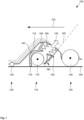
- Figure 1 shows a soil processing device 100 which is designed to process a soil 105.
- the soil processing device 100 comprises a processing device 110 which is designed, for example, to clean the soil 105 by means of pneumatic negative pressure.
- the floor processing device 100 shown is, by way of example, part of a vacuum robot, in particular a vacuum cleaner robot. In other variants, however, other floor processing machines can also be implemented on the basis of the floor processing device 100, the processing devices 110 of which can be set up to act on the floor 105 in a different way.
- the floor processing device 100 can also be part of a conventional vacuum cleaner or a cordless vacuum cleaner.
- the cordless vacuum cleaner can be equipped with different attachments and/or accessories and can also be referred to as a universal handheld vacuum cleaner (Multi Use Handstick, MUH).
- MUH Multi Use Handstick
- the soil processing device 100 comprises a chassis 115, which can also be referred to as a chassis, and which can comprise a base plate or a housing of the soil processing device 100.
- the soil processing device 100 also comprises a running gear 120, which connects the chassis 115 to the ground 105.
- the running gear 120 comprises a first wheel 125 and at least one second wheel 130.
- the wheels 125, 130 or their axles are arranged longitudinally offset.
- the first wheel 125 is unsteered in the present case and can, for example, comprise a trailing wheel or a roller and usually has a small diameter in the range of approximately 15 millimeters.
- the first wheel 125 can also be replaced by a sliding element.
- the second wheel 130 is designed as a drive wheel, for example.
- several second wheels 130 are mounted laterally offset on the soil processing device 100 and connected to individually controllable motors.
- the axes of the second wheels 130 can be aligned with one another.
- the wheels 125, 130 can be set to individual speeds in order to accelerate, brake, steer or rotate the soil processing device 100.
- the diameter of the second wheels 130 can be in the range of approximately 70 millimeters.
- the soil processing device 100 usually also includes a control device to control a movement of the soil processing device 100 over the ground 105 and/or a function of the processing device 110. Furthermore, an energy storage device and environmental sensors can be provided. These and other possible elements are shown in Figure 1 not shown.
- the processing device 110 is designed as a suction device, of which only a portion close to the floor 105 is shown, which can be referred to as suction mouth 140.
- the suction device usually comprises a blower, a dirt container and a filter, which are in Figure 1 are not shown.
- the suction device is designed to cause an air flow 145 through the suction mouth 140 so that air from the area between the suction mouth 140 and the floor 105. This can carry dirt particles from the floor 105. The air can be directed into the dirt container. Air escaping from the dirt container can be filtered to retain the protection in the container.
- the suction mouth 140 can be sealed against the floor 105 on a preferably circumferential curve by means of a sealing element, for example by means of a rubber lip, a bristle strip or a strip of felt.
- the sealing element preferably has a predetermined permeability for horizontally flowing air on a hard, flat surface.
- the sealing element can be continuous or have one or more interruptions.
- the sealing element can be adjusted vertically relative to the chassis 115.
- the sealing element can be adjusted between different predetermined heights, for example between a first in which it is designed to rest on the floor 105 and a second in which it is raised upwards so that the suction mouth 140 can rest directly on the floor 105 or can be guided over the floor 105 by means of another element.
- a corresponding sealing element can be attached to the chassis 115.
- the suction mouth 140 can move relative to the chassis 115 by means of a guide 150. If the path 155 runs straight, it can be referred to as a linear guide.
- the guide 150 can be designed, for example, as a sliding block guide with a slotted nut accommodated in a groove.
- the guide 150 can also be designed, for example, to be telescopic, or a sleeve can run along the path 155 on a rail.
- a bellows 160 can be provided for the movable and airtight connection of the suction mouth 140 to the chassis 115 or the dirt container.
- the suction mouth 140 can be pressed against the floor 105 due to its weight or by means of an elastic element 165 along the track 155.
- the suction mouth 140 is preferably supported against the floor 105 by means of a support element 170.
- the support element 170 can comprise, for example, a wheel, a roller or a cylinder.
- a diameter of a rotatable support element can be approximately 5 millimeters.
- the support element 170 can also be arranged non-rotatably and designed to slide over the floor 105.
- the A rotary brush 175 that can be rotated about a horizontal axis is also attached to the suction mouth 140. Dirt particles in the area of the floor 105 can be loosened by means of the rotary brush 175 in order to be transported away with the air flow 145.
- the track 155 runs straight, for example.
- the guide 150 can be set up to move the suction mouth 140 from the position of the soil processing device 100 shown on a flat floor 105 in a direction along the track 155. This mobility can make it possible to hold the suction mouth 140 on the floor 105 when the soil processing device 100 travels over an uneven surface.
- the track 155 runs backwards and upwards, so that it forms an angle 180 with the floor 105 or a plane parallel to it. A movement in the opposite direction can also be provided, for which the track 155 can be extended accordingly.
- the angle 180 is usually fixed and is preferably greater than approximately 20° and more preferably less than approximately 45°.
- the angle 180 is preferably in a longitudinal plane of the soil cultivation device 100 and can also assume larger values in other variants.
- the track 155 can be perpendicular to the ground 105, so that the angle 180 is a right angle and amounts to 90°.
- the angle 180 shown can also be greater than 90°, so that the track 155 is inclined forwards in the longitudinal plane of the soil cultivation device 100.
- the angle 180 should be smaller than approximately 160°.
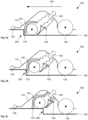
- Figure 2 shows a soil tillage device 100 overcoming an obstacle 205. Successive phases of overcoming are shown in Figures 2A, 2B and 2C shown.
- an obstacle 205 is assumed which is present as a threshold and which must be climbed by the soil processing device 100.
- a step can also be included, for example, which the soil processing device 100 must travel down.
- Other possible obstacles 205 include a ditch, which can be understood as a combination of a step with a threshold, or a general unevenness in the ground.
- the first wheel 125 is in front with respect to the direction of travel 135, is followed by the support element 170 and that this the second wheel 130 follows. Size and distance relationships in Figure 2 are to be regarded as exemplary.
- Figure 1 The obstacle 205 is first overcome by the first wheel 125, so that the Figure 2A
- the guide 150 has allowed a downward movement of the suction mouth 140 relative to the chassis 115, so that the suction mouth 140 is further than in Figure 1 protrudes downwards from the soil cultivation device 100.
- the support element 170 is located in front of the obstacle 205 and the suction mouth 140 is guided at a height above the ground 105 which ensures that it can be cleaned by the air flow 145.
- the support element 170 is displaced along the path 155 at the obstacle 205 so that it moves less far than in Figure 1 protrudes from the bottom of the soil tillage device 100.
- This situation is in Figure 2B shown.
- the distance between the suction mouth 140 and the floor 105 has become so large that dirt particles can no longer be picked up from the floor 105.
- the air that does not enter the suction mouth 140 directly from near the floor is also referred to as false air, secondary air or incorrect air.
- the lifting of the suction mouth 140 is unavoidable in order to lift it over the obstacle 205. The lifting takes place from a section of the floor 105 that has already been cleaned, so that the cleaning result is not impaired at this point.
- the suction mouth 140 can be brought back to its working distance with respect to the floor 105 after overcoming the obstacle 205.
- This situation is in Figure 2C It can be seen that the suction mouth 140 is almost flush with the floor 105 so that it can be cleaned as intended.
- the floor 105 can advantageously be worked on both sides up to the obstacle 205 so that no dirt streaks can form on the obstacle 205.
- the suction mouth 140 is pressed further into the underside of the floor processing device 100 by the guide 150 on the track 155 than in the configuration shown in Figure 1 After the obstacle 205 has been overcome by the second wheel 130, the position shown in Figure 1 constellation shown.
- Figure 3 shows a soil tillage device 100 in a further variant.
- the guide 150 is not designed as a linear guide, but as a swing arm 305.
- the suction mouth 140 is attached, optionally rotatably, to one end of a swing arm 305, the other end of which is mounted around a rotation axis 310 that runs transversely to the direction of travel 135.
- the track 155, along which the suction mouth 140 is movable relative to the chassis 115, follows a circular arc.
- the angle 180 can correspond to that of the track 155 in the Figure 1 illustrated embodiment, as indicated by a broken line which forms a tangent to the circular arc 155 and corresponds to the path 155 of Figure 1
- the rotation axis 310 is located in front of the suction mouth 140 with respect to the direction of travel 135 as shown, this is referred to as a pulled swing arm 305; if the rotation axis 310 is located behind the suction mouth 140, this is a pushed swing arm 305.
- the elastic element 165 can be designed as a spiral spring in this embodiment instead of the Figure 1 cylindrical spring shown.
- a soil cultivation device which comprises: a chassis; a running gear for guiding the chassis over a ground; a processing device for processing the ground; a guide for attaching the processing device so as to be movable along a predetermined path with respect to the chassis, wherein the path extends in a vertical direction with respect to the ground, wherein the processing device comprises a suction mouth and wherein the path encloses a predetermined angle with a plane parallel to the ground when the soil cultivation device is standing on a level ground, wherein the angle is a maximum of approximately 45°.
- the soil tillage device according to variant A can be designed such that the track encloses a predetermined angle with a plane parallel to the ground when the soil tillage device is standing on a level ground.
- the soil tillage device according to variant B soil tillage device can be designed to travel over the soil in a predetermined direction of travel, whereby the track can be inclined against the direction of travel.
- the tillage device in the soil tillage device according to one of the preceding variants, can be supported relative to the ground by means of a support element.
- the soil tillage device according to one of the preceding variants can further comprise an elastic element for pressing the tillage device against the ground relative to the chassis.
- the guide in the case of the soil tillage device according to one of the preceding variants, can comprise a linear guide and the track can run straight.
- the guide can comprise a rocker and the path can follow a circular arc.
- the soil tillage device can comprise a rotary brush.
- the soil tillage device may comprise a suction mouth.
- the soil tillage device according to one of the preceding variants of soil tillage device can be designed to travel over the soil (105) in a predetermined direction of travel (135), wherein the chassis (120) comprises a first (125) and a second wheel (130), and the wheels (125, 130) and the tillage device (110) are mounted on the chassis (115) at a distance from one another along the direction of travel (135).
Landscapes
- Engineering & Computer Science (AREA)
- Mechanical Engineering (AREA)
- Soil Working Implements (AREA)
- Electric Vacuum Cleaner (AREA)
- Cleaning In General (AREA)
Description
- Die Erfindung betrifft eine Bodenbearbeitungseinrichtung. Insbesondere betrifft die Erfindung eine Einrichtung zur Bearbeitung eines Bodens mittels eines pneumatischen Unterdrucks.
- Ein Staubsaugroboter ist dazu eingerichtet, über einen Boden zu fahren und diesen mittels eines Saugwerks zu reinigen. Das Saugwerk umfasst einen Saugmund, der im Bereich des Bodens liegt und in den mit Schmutz vermengte Luft eintreten kann. Dabei beträgt ein Abstand zwischen dem Saugmund und dem Boden üblicherweise nur wenige Millimeter. Sollte der Saugmund zu weit vom Boden abgehoben werden, so kann die Luftströmung derart gestört werden, dass Schmutzpartikel im betreffenden Bereich nicht zuverlässig vom Boden entfernt werden können.
- Der Saugmund kann vom Boden abgehoben werden, wenn dieser eine größere Unebenheit wie eine Stufe oder eine Schwelle umfasst. Manche Staubsaugroboter haben daher Schwierigkeiten, beispielsweise einen Übergang zwischen einem Parkett und einem darauf liegenden Teppich oder einen Bereich an einer Türschwelle zuverlässig zu reinigen.
- Es wurde vorgeschlagen, im Bereich des Saugmundes eine flexible Dichtung, beispielsweise in Form einer Dichtlippe, anzubringen, um eine gewünschte Strömung von Luft in den Saugmund sicherzustellen. Eine solche Dichtung kann jedoch häufigem oder intensivem Bodenkontakt ausgesetzt sein, sodass sie rasch verschleißen kann. Außerdem kann die Dichtung Schmutzpartikel über den Boden schieben, sodass das Reinigungsergebnis beeinträchtigt sein kann. Übliche Dichtungen können auch nur geringe vertikale Höhen ausgleichen, sodass ihr Effekt häufig nicht überzeugen kann.
-
US 2012 / 0 096 656 A1 beschreibt eine Flügelanordnung für eine autonome Reinigungseinrichtung. DieDE 37 32 483 A1 offenbart ein Mundstück für einen Staubsauger. Aus derDE 10 2010 000 577 A1 ist ein Bürstengerät insbesondere für einen Staubsauger bekannt. DieJP 2015 - 000 210 A KR 10 2014 008 2218 A US 2018/213987 A1 offenbart einen Reinigungsroboter. - Eine der vorliegenden Erfindung zu Grunde liegende Aufgabe besteht in der Angabe einer verbesserten Bearbeitungseinrichtung für einen Boden. Ein Aspekt der Erfindung löst die Aufgabe mittels des Gegenstands des unabhängigen Anspruchs. Unteransprüche geben bevorzugte Ausführungsformen wieder.
- Gemäß einem Aspekt der Erfindung ist eine Bodenbearbeitungseinrichtung offenbart, welche umfasst: ein Chassis; ein Fahrwerk, um das Chassis über einen Boden zu führen; eine Bearbeitungseinrichtung zur Bearbeitung des Bodens; eine Führung zur Anbringung der Bearbeitungseinrichtung beweglich entlang einer vorbestimmten Bahn bezüglich des Chassis, wobei sich die Bahn bezüglich des Bodens in einer vertikalen Richtung erstreckt.
- Nach einem nebengeordneten Aspekt umfasst eine Bodenbearbeitungseinrichtung ein Chassis; ein Fahrwerk, um das Chassis über einen Boden zu führen; eine Bearbeitungseinrichtung zur Bearbeitung des Bodens; und eine Führung zur Anbringung wenigstens eines bodennahen Endes der Bearbeitungseinrichtung beweglich entlang einer vorbestimmten Bahn bezüglich des Chassis. Dabei erstreckt sich die Bahn bezüglich des Bodens in einer vertikalen Richtung.
- Wird das Chassis über einen unebenen Boden bewegt, so kann durch die Führung sichergestellt werden, dass ein vorbestimmter Abstand der Bearbeitungseinrichtung zum Boden eingehalten wird. Sollte das Chassis beispielsweise nach oben bewegt werden, sodass der Abstand zu groß zu werden droht, so kann die Bearbeitungseinrichtung gegenüber dem Chassis nach unten bewegt werden. Sollte in umgekehrter Weise das Chassis derart bewegt werden, dass der Abstand zu klein zu werden droht, so kann die Bearbeitungseinrichtung gegenüber dem Chassis nach oben bewegt werden. Insgesamt können ein vertikaler Mindest- und/oder Maximalabstand der Bearbeitungseinrichtung zum Boden verbessert eingehalten werden.
- Es ist bevorzugt, dass die Bahn mit einer zum Boden parallelen Ebene einen vorbestimmten Winkel einschließt, wenn die Bodenbearbeitungseinrichtung auf einem ebenen Boden steht. Durch passende Wahl des Winkels kann ein mechanischer Widerstand, der zu überwinden ist, um die Bearbeitungseinrichtung aufgrund einer horizontalen Bewegung der Bodenbearbeitungseinrichtung in vertikaler Richtung zu bewegen, variiert werden. So kann ein vorbestimmtes Bewegungsverhalten der Bearbeitungseinrichtung durch Wahl eines passenden Winkels erzielt werden.
- Die Bodenbearbeitungseinrichtung kann dazu eingerichtet sein, in einer vorbestimmten Fahrtrichtung über den Boden zu fahren. Dabei kann die Bahn entgegen der Fahrtrichtung geneigt sein. Zur Bestimmung der Neigung kann davon ausgegangen werden, dass die Bodenbearbeitungseinrichtung auf einem ebenen Boden steht. Durch die Neigung kann die Bearbeitungseinrichtung bezüglich des Chassis in einer Richtung ausgelenkt werden, die entgegen der Fahrtrichtung und vom Boden nach oben verläuft. Anders ausgedrückt kann sich die Bearbeitungseinrichtung, während sich die Bodenbearbeitungseinrichtung in einer vorbestimmten Fahrtrichtung über einen Boden bewegt, in eine Richtung bewegen, die nach oben und nach hinten verläuft. Dadurch kann insbesondere eine Bewegung der Bearbeitungseinrichtung bezüglich des Chassis nach oben leichter aus der horizontalen Bewegung der Bodenbearbeitungseinrichtung hergestellt werden. Insbesondere wenn die Einrichtung ein bodenfestes Hindernis überfährt, beispielsweise eine Schwelle oder eine Stufe, so kann die Bearbeitungseinrichtung verbessert in Bodennähe gehalten sein.
- Der genannte Winkel beträgt maximal ca. 45°. Je kleiner der Winkel ist, desto leichter kann eine vertikale Bewegung der Bearbeitungseinrichtung aus der horizontalen Bewegung der Bodenbearbeitungseinrichtung bewirkt werden. Allerdings sollte der Winkel größer als ca. 20° sein, um eine ausreichende vertikale Bewegung der Bearbeitungseinrichtung zu ermöglichen. Der genannte Winkel ist unter den oben genannten Randbedingungen zu verstehen, wenn die Bodenbearbeitungseinrichtung auf einem ebenen Boden steht.
- Die Bearbeitungseinrichtung kann mittels eines Stützelements gegenüber dem Boden abgestützt sein. Das Stützelement kann insbesondere ein Rad, eine Rolle oder ein Gleitelement umfassen. Das Stützelement kann durch die bahngesteuerte Führung der Bearbeitungseinrichtung verbessert am Boden gehalten werden, auch wenn die Bodenbearbeitungseinrichtung über eine Unebenheit im Boden fährt.
- Die Bearbeitungseinrichtung kann im Wesentlichen aufgrund ihrer Gewichtskraft am Boden gehalten sein. Zur Herstellung eines vorbestimmten Anlageverhaltens kann der Bearbeitungseinrichtung ein Massenelement zugefügt werden, um ihre Gewichtskraft zu vergrößern.
- In einer weiteren Variante ist ein elastisches Element vorgesehen, um die Bearbeitungseinrichtung gegenüber dem Chassis an den Boden zu drücken. Das elastische Element kann insbesondere eine Feder, ein Gummi- oder ein Kunststoffelement umfassen. Optional ist ein Dämpfungselement vorgesehen. Eine Anpresskraft der Bearbeitungseinrichtung am Boden kann so verbessert gesteuert werden. Durch passende Wahl einer Kraft-Weg-Kennlinie des elastischen Elements kann das Anpressverhalten über den Weg der Bearbeitungseinrichtung entlang der Bahn passend gewählt werden. Dabei ist auch ein nicht linearer Kraftverlauf entlang der Bahn möglich.
- In einer ersten Variante umfasst die Führung eine Linearführung und die Bahn verläuft gerade. Die Linearführung kann beispielsweise mittels eines in einer geraden Nut geführten Nutensteins, mittels eines Linearkugellagers oder mittels eines linearen Gleitlagers realisiert sein. Durch die lineare Führung kann ein Bewegungsraum der Bearbeitungseinrichtung in der Bodenbearbeitungseinrichtung verkleinert oder vorteilhafter geformt sein, sodass die Bodenbearbeitungseinrichtung kompakter aufgebaut sein kann.
- In einer zweiten Variante umfasst die Führung eine Schwinge, wobei die Bahn einem Kreisbogen folgt. Dazu können eine gezogene oder eine geschobene Schwinge verwendet werden. Eine Drehachse der Schwinge verläuft bevorzugt horizontal und senkrecht zu einer Fahrtrichtung, wenn sich die Bodenbearbeitungseinrichtung über den Boden bewegt. Mittels der Schwinge kann die Bearbeitungseinrichtung verbessert präzise geführt werden. Insbesondere wenn die Bearbeitungseinrichtung entlang der Drehachse der Schwinge lang ist, können ihre Enden mittels der Schwinge verbessert miteinander gekoppelt geführt werden.
- In einer dritten Variante verläuft die Bahn entlang einer allgemeinen Kurve, wobei die Führung insbesondere mittels eines in einer Nut geführten Nutensteins realisiert ist. Die Bahn kann beispielsweise einen Abschnitt einer Spirale, einer Evolvente oder einer Sigmoidfunktion folgen. Dazu kann die Führung insbesondere als Kulissenführung ausgeführt sein.
- In einer weiteren Variante umfasst die Bearbeitungseinrichtung eine Rotationsbürste. Die Rotationsbürste kann sich um eine Drehachse drehen, die horizontal und bevorzugt senkrecht zu einer Fahrtrichtung verläuft, wenn die Bodenbearbeitungseinrichtung entlang der Fahrtrichtung über den Boden fährt. Eine autonome Bodenbearbeitungsmaschine, die eine solche Bearbeitungseinrichtung umfasst, kann auch als Kehrroboter bezeichnet werden. Eine um eine vertikale Drehachse drehbare Rotationsbürste ist ebenfalls möglich. In weiteren Varianten kann die Bearbeitungseinrichtung auch ein Schneidwerk umfassen, wobei die Bodenbearbeitungsmaschine als automatischer Rasenmäher bezeichnet werden kann, oder eine Wischeinrichtung, wobei die Bodenbearbeitungsmaschine als Wischroboter bezeichnet werden kann.
- Es ist besonders bevorzugt, dass die Bearbeitungseinrichtung einen Saugmund umfasst. Der Saugmund kann Teil einer Saugeinrichtung sein, die dazu eingerichtet ist, Luft im Bereich zwischen der Bearbeitungseinrichtung und dem Boden einzusaugen. Eine autonome Bodenbearbeitungsmaschine, die eine solche Bearbeitungseinrichtung umfasst, kann auch als Saugroboter bezeichnet werden. Weiter bevorzugt ist nur der Saugmund beweglich gegenüber dem Chassis angebracht, während weitere Elemente der Bearbeitungseinrichtung auch unbeweglich am Chassis angebracht sein können. Allgemein ist bevorzugt, dass die Bodenbearbeitungseinrichtung ein Haushaltsgerät umfasst, also zum Einsatz innerhalb eines Haushalts eingerichtet ist. Je nach Variante können dabei ein Innenbereich oder ein Außenbereich des Haushalts bearbeitet werden.
- Die Bodenbearbeitungseinrichtung kann dazu eingerichtet sein, in einer vorbestimmten Fahrtrichtung über den Boden zu fahren, wobei das Fahrwerk ein erstes Rad auf einer ersten Achse und ein zweites Rad auf einer zweiten Achse umfasst. Die Achsen und die Bearbeitungseinrichtung können entlang der Fahrtrichtung voneinander beabstandet am Chassis angebracht sein. Entlang der Fahrtrichtung kann also die Bearbeitungseinrichtung beiden Rädern vorauslaufen, sich zwischen beiden Achsen befinden oder beiden Achsen nachlaufen. Die Anordnung der Bearbeitungseinrichtung bezüglich der Achsen kann bestimmen, in welcher Weise die Bearbeitungseinrichtung entlang der Bahn geführt wird, wenn die Bodenbearbeitungseinrichtung über eine Stufe, eine Schwelle oder eine Unebenheit des Bodens fährt. Zur Steigerung einer seitlichen Stabilität können an einer Achse auch mehrere Räder angebracht sein.
- Nach einem weiteren Aspekt der vorliegenden Erfindung umfasst eine Bodenbearbeitungsmaschine eine hierin beschriebene Bodenbearbeitungseinrichtung. Die Bodenbearbeitungsmaschine kann insbesondere zum autonomen Bearbeiten eines Bodens in einem Haushalt eingerichtet sein und beispielsweise als Staubsaugroboter oder Kehrroboter ausgebildet sein.
- Nach wieder einem weiteren Aspekt der vorliegenden Erfindung umfasst ein Staubsauger eine hierin beschriebene Bodenbearbeitungseinrichtung. Der Staubsauger kann konventionell kabelgebunden oder als drahtloses Gerät realisiert sein und ist zur Bearbeitung eines Bodens in einem Haushalt durch eine Person eingerichtet.
- Die Erfindung wird nun unter Bezug auf die beiliegenden Figuren genauer beschrieben, in denen:
- Figur 1
- eine Bodenbearbeitungseinrichtung;
- Figur 2
- eine Bodenbearbeitungseinrichtung beim Überwinden eines Hindernisses; und
- Figur 3
- eine Bodenbearbeitungseinrichtung in einer weiteren Variante darstellt.
-
Figur 1 zeigt eine Bodenbearbeitungseinrichtung 100, die dazu eingerichtet ist, einen Boden 105 zu bearbeiten. Dazu umfasst die Bodenbearbeitungseinrichtung 100 eine Bearbeitungseinrichtung 110, die vorliegend beispielhaft dazu eingerichtet ist, den Boden 105 mittels pneumatischen Unterdrucks zu reinigen. Die inFigur 1 dargestellte Bodenbearbeitungseinrichtung 100 ist beispielhaft Teil eines Saugroboters, insbesondere eines Staubsaugroboters. In anderen Varianten können jedoch auch andere Bodenbearbeitungsmaschinen auf der Basis der Bodenbearbeitungseinrichtung 100 realisiert sein, deren Bearbeitungseinrichtungen 110 dazu eingerichtet sein können, in anderer Weise auf den Boden 105 einzuwirken. Insbesondere kann die Bodenbearbeitungseinrichtung 100 Teil auch eines konventionellen Staubsaugers oder eines kabellosen Saugers sein. Der kabellose Sauger kann mit unterschiedlichen Vorsätzen und/oder Zubehörteilen ausgestattet werden und kann auch als universeller Handsauger (Multi Use Handstick, MUH) bezeichnet werden. - Die Bodenbearbeitungseinrichtung 100 umfasst ein Chassis 115, das auch als Fahrgestell bezeichnet werden kann, und das eine Bodenplatte oder ein Gehäuse der Bodenbearbeitungseinrichtung 100 umfassen kann. Ferner umfasst die Bodenbearbeitungseinrichtung 100 ein Fahrwerk 120, das eine Verbindung des Chassis 115 zum Boden 105 herstellt. Vorliegend umfasst das Fahrwerk 120 ein erstes Rad 125 und wenigstens ein zweites Rad 130. Bezüglich einer angenommenen Fahrtrichtung 135 der Bodenbearbeitungseinrichtung 100 über den Boden 105 sind die Räder 125, 130 beziehungsweise deren Achsen längs versetzt angeordnet. Das erste Rad 125 ist vorliegend ungelenkt und kann beispielsweise ein nachlaufendes Rad oder eine Walze umfassen und hat üblicherweise einen kleinen Durchmesser im Bereich von ca. 15 Millimetern. In einer weiteren Variante kann das erste Rad 125 auch durch ein Gleitelement ersetzt sein.
- Das zweite Rad 130 ist beispielhaft als Antriebsrad ausgeführt. Üblicherweise sind mehrere zweite Räder 130 seitlich versetzt an der Bodenbearbeitungseinrichtung 100 angebracht und mit einzeln steuerbaren Motoren verbunden. Achsen der zweiten Räder 130 können miteinander fluchten. Durch passende Ansteuerung der Motoren können die Räder 125, 130 in individuelle Drehzahlen versetzt werden, um die Bodenbearbeitungseinrichtung 100 zu beschleunigen, abzubremsen, zu lenken oder zu drehen. Ein Durchmesser der zweiten Räder 130 kann im Bereich von ca. 70 Millimetern liegen.
- Üblicherweise umfasst die Bodenbearbeitungseinrichtung 100 über die dargestellten Elemente hinaus noch eine Steuereinrichtung, um eine Bewegung der Bodenbearbeitungseinrichtung 100 über den Boden 105 und/oder eine Funktion der Bearbeitungseinrichtung 110 zu steuern. Ferner können ein Energiespeicher und Umfeldsensoren vorgesehen sein. Diese und weitere mögliche Elemente sind in
Figur 1 nicht dargestellt. - Die Bearbeitungseinrichtung 110 ist vorliegend als Saugeinrichtung ausgebildet, von der lediglich ein dem Boden 105 naher Abschnitt dargestellt ist, der als Saugmund 140 bezeichnet werden kann. Zusätzlich umfasst die Saugeinrichtung üblicherweise ein Gebläse, einen Schmutzbehälter und einen Filter, die in
Figur 1 nicht dargestellt sind. Die Saugeinrichtung ist dazu eingerichtet, einen Luftstrom 145 durch den Saugmund 140 zu bewirken, sodass Luft aus dem Bereich zwischen dem Saugmund 140 und dem Boden 105 eingesaugt wird. Dabei können Schmutzpartikel vom Boden 105 mitgerissen werden. Die Luft kann in den Schmutzbehälter geleitet werden. Aus dem Schmutzbehälter austretende Luft kann gefiltert werden, um den Schutz im Behälter zurückzuhalten. - Der Saugmund 140 kann gegenüber dem Boden 105 auf einer bevorzugt umlaufenden Kurve mittels eines Dichtelements abgedichtet sein, beispielsweise mittels einer Gummilippe, eines Borstenstreifens oder eines Streifens Filz. Bevorzugt weist das Dichtelement auf einem harten, ebenen Untergrund eine vorbestimmte Durchlässigkeit für horizontal strömende Luft auf. Das Dichtelement kann durchgehend sein oder eine oder mehrere Unterbrechungen aufweisen. In einer Ausführungsform kann das Dichtelement vertikal gegenüber dem Chassis 115 verstellt werden. Das Dichtelement kann zwischen verschiedenen vorbestimmten Höhen verstellt werden, beispielsweise zwischen einer ersten, in der er dazu eingerichtet ist, auf dem Boden 105 aufzuliegen, und einer zweiten, in der er nach oben abgehoben ist, sodass der Saugmund 140 direkt auf dem Boden 105 aufliegen oder mittels eines anderen Elements über den Boden 105 geführt werden kann. In einer weiteren Ausführungsform kann ein entsprechendes Dichtelement am Chassis 115 angebracht sein.
- Es wird vorgeschlagen, den Saugmund 140 mittels einer Führung 150 entlang einer vorbestimmten Bahn 155 beweglich gegenüber dem Chassis 115 anzubringen. Verläuft die Bahn 155 gerade, kann von einer Linearführung gesprochen werden. Die Führung 150 kann beispielsweise als Kulissenführung mit einem in einer Nut aufgenommenen Nutenstein ausgeführt sein. Die Führung 150 kann auch beispielsweise teleskopisch ausgeführt sein oder eine Hülse kann entlang der Bahn 155 an einer Schiene entlanglaufen.
- Zur beweglichen und luftdichten Verbindung des Saugmunds 140 mit dem Chassis 115 oder dem Schmutzbehälter kann ein Faltenbalg 160 vorgesehen sein. Der Saugmund 140 kann aufgrund seiner Gewichtskraft oder mittels eines elastischen Elements 165 entlang der Bahn 155 gegen den Boden 105 gepresst werden. Bevorzugt ist der Saugmund 140 mittels eines Stützelements 170 gegenüber dem Boden 105 abgestützt. Das Stützelement 170 kann beispielsweise ein Rad, eine Rolle oder eine Walze umfassen. Ein Durchmesser eines drehbaren Stützelements kann bei ca. 5 Millimetern liegen. In einer weiteren Variante kann das Stützelement 170 auch nicht drehbar angeordnet und dazu eingerichtet sein, über den Boden 105 zu gleiten. In der dargestellten, bevorzugten Variante ist am Saugmund 140 zusätzlich eine Rotationsbürste 175 angebracht, die um eine horizontale Achse gedreht werden kann. Schmutzpartikel im Bereich des Bodens 105 können mittels der Rotationsbürste 175 gelöst werden, um mit dem Luftstrom 145 abtransportiert zu werden.
- In der dargestellten Variante verläuft die Bahn 155 beispielhaft gerade. Die Führung 150 kann dazu eingerichtet sein, den Saugmund 140 aus der dargestellten Position der Bodenbearbeitungseinrichtung 100 auf einem ebenen Boden 105 in eine Richtung entlang der Bahn 155 zu bewegen. Diese Beweglichkeit kann es erlauben, den Saugmund 140 am Boden 105 zu halten, wenn die Bodenbearbeitungseinrichtung 100 über eine Unebenheit fährt. Bezüglich der Fahrtrichtung 135 verläuft die Bahn 155 nach hinten und nach oben, sodass sie mit dem Boden 105 oder einer dazu parallelen Ebene einen Winkel 180 einschließt. Auch eine Bewegung in umgekehrter Richtung kann vorgesehen sein, wozu die Bahn 155 entsprechend verlängert sein kann. Der Winkel 180 ist üblicherweise fest gewählt und beträgt bevorzugt größer als ca. 20° und weiter bevorzugt kleiner als ca. 45°.
- Der Winkel 180 liegt bevorzugt in einer Längsebene der Bodenbearbeitungseinrichtung 100 und kann in anderen Varianten auch größere Werte annehmen. In einer Variante kann die Bahn 155 senkrecht auf dem Boden 105 stehen, sodass der Winkel 180 ein rechter Winkel ist und 90° beträgt. In noch einer weiteren Variante kann der eingezeichnete Winkel 180 auch größer als 90° sein, sodass die Bahn 155 in der Längsebene der Bodenbearbeitungseinrichtung 100 nach vorne geneigt ist. Dabei sollte der Winkel 180 kleiner als ca. 160° sein.
-
Figur 2 zeigt eine Bodenbearbeitungseinrichtung 100 beim Überwinden eines Hindernisses 205. Zeitlich aufeinander folgende Phasen des Überwindens sind inFiguren 2A, 2B und 2C dargestellt. Rein beispielhaft wird von einem Hindernis 205 ausgegangen, das als Schwelle vorliegt und von der Bodenbearbeitungseinrichtung 100 erklommen werden muss. In einer anderen Variante kann auch beispielsweise eine Stufe umfasst sein, welche die Bodenbearbeitungseinrichtung 100 hinunterfahren muss. Weitere mögliche Hindernisse 205 umfassen einen Graben, der als Kombination einer Stufe mit einer Schwelle aufgefasst werden kann, oder eine allgemeine Bodenunebenheit. Für die vorliegenden Betrachtungen wird davon ausgegangen, dass das erste Rad 125 bezüglich der Fahrtrichtung 135 vorne liegt, vom Stützelement 170 gefolgt wird und dass diesem das zweite Rad 130 folgt. Größen- und Abstandsverhältnisse inFigur 2 sind als beispielhaft zu betrachten. - Fährt die Bodenbearbeitungseinrichtung 100 über einen ebenen Boden 105, so ergibt sich das in
Figur 1 dargestellte Bild. Das Hindernis 205 wird zunächst vom ersten Rad 125 überwunden, sodass sich die inFigur 2A gezeigte Konstellation ergibt. Die Führung 150 hat eine Bewegung des Saugmunds 140 bezüglich des Chassis 115 nach unten erlaubt, sodass der Saugmund 140 weiter als inFigur 1 nach unten aus der Bodenbearbeitungseinrichtung 100 herausragt. Das Stützelement 170 befindet sich noch vor dem Hindernis 205 und der Saugmund 140 ist einer Höhe über dem Boden 105 geführt, die sicherstellt, dass dieser durch den Luftstrom 145 gereinigt werden kann. - Fährt die Bodenbearbeitungseinrichtung 100 weiter entlang der Fahrtrichtung 135, so wird das Stützelement 170 am Hindernis 205 entlang der Bahn 155 verschoben, sodass es weniger weit als in
Figur 1 aus der Unterseite der Bodenbearbeitungseinrichtung 100 ragt. Diese Situation ist inFigur 2B dargestellt. Ein Abstand des Saugmunds 140 vom Boden 105 ist hier so groß geworden, dass Schmutzpartikel vom Boden 105 nicht mehr aufgenommen werden können. Die nicht unmittelbar aus Bodennähe in den Saugmund 140 eintretende Luft wird auch als Falschluft, Nebenluft oder Fehlluft bezeichnet. Das Anheben des Saugmunds 140 ist unvermeidlich, um diesen über das Hindernis 205 zu heben. Das Abheben erfolgt von einem Abschnitt des Bodens 105, der bereits gereinigt wurde, sodass das Reinigungsergebnis an dieser Stelle nicht beeinträchtigt ist. - Sobald das Stützelement 170 das Hindernis 205 überwunden hat, kann der Saugmund 140 wieder in seine Arbeitsentfernung bezüglich des Bodens 105 nach dem Überwinden des Hindernisses 205 gebracht werden. Diese Situation ist in
Figur 2C dargestellt. Es ist zu sehen, dass der Saugmund 140 annähernd bündig mit dem Boden 105 abschließt, sodass dieser wie vorgesehen gereinigt werden kann. Vorteilhaft kann der Boden 105 beidseits bis zum Hindernis 205 bearbeitet werden, sodass sich kein Schmutzstreifen am Hindernis 205 bilden kann. In der dargestellten Konstellation ist der Saugmund 140 durch die Führung 150 auf der Bahn 155 weiter in die Unterseite der Bodenbearbeitungseinrichtung 100 eingedrückt als in der inFigur 1 dargestellten Position. Nach dem Überwinden des Hindernisses 205 durch das zweite Rad 130 kann sich erneut die inFigur 1 dargestellte Konstellation ergeben. -
Figur 3 zeigt eine Bodenbearbeitungseinrichtung 100 in einer weiteren Variante. Im Unterschied zu der inFigur 1 dargestellten Variante ist hier die Führung 150 nicht als Linearführung, sondern als Schwinge 305 ausgeführt. Der Saugmund 140 ist, optional drehbar, an einem Ende einer Schwinge 305 angebracht, deren anderes Ende um eine Drehachse 310 gelagert ist, die quer zur Fahrtrichtung 135 verläuft. Die Bahn 155, entlang der der Saugmund 140 gegenüber dem Chassis 115 beweglich ist, folgt hierbei einem Kreisbogen. In der dargestellten Position auf einem ebenen Boden 105 kann der Winkel 180 demjenigen der Bahn 155 in der inFigur 1 dargestellten Ausführungsform entsprechen, wie durch eine unterbrochene Linie angedeutet ist, die eine Tangente an den Kreisbogen 155 bildet und der Bahn 155 ausFigur 1 entspricht. Liegt die Drehachse 310 bezüglich der Fahrtrichtung 135 wie gezeigt vor dem Saugmund 140, wird von einer gezogenen Schwinge 305 gesprochen; liegt die Drehachse 310 hinter dem Saugmund 140, handelt es sich um eine geschobene Schwinge 305. Das elastische Element 165 kann in dieser Ausführungsform als Spiralfeder statt der inFigur 1 dargestellten zylindrischen Feder ausgeführt sein. - Allgemein werden verschiedene Varianten und Aspekte einer Bodenbearbeitungseinrichtung beschrieben. Insbesondere ist nach einer Variante A eine Bodenbearbeitungseinrichtung offenbart, welche umfasst: ein Chassis; ein Fahrwerk, um das Chassis über einen Boden zu führen; eine Bearbeitungseinrichtung zur Bearbeitung des Bodens ; eine Führung zur Anbringung der Bearbeitungseinrichtung beweglich entlang einer vorbestimmten Bahn bezüglich des Chassis , wobei sich die Bahn bezüglich des Bodens in einer vertikalen Richtung erstreckt, wobei die Bearbeitungseinrichtung einen Saugmund umfasst und wobei die Bahn mit einer zum Boden parallelen Ebene einen vorbestimmten Winkel einschließt, wenn die Bodenbearbeitungseinrichtung auf einem ebenen Boden steht, wobei der Winkel maximal ca. 45° beträgt.
- In Variante B kann die Bodenbearbeitungseinrichtung nach Variante A derart ausgebildet sein, dass die Bahn mit einer zum Boden parallelen Ebene einen vorbestimmten Winkel einschließt, wenn die Bodenbearbeitungseinrichtung auf einem ebenen Boden steht.
- In Variante C kann die Bodenbearbeitungseinrichtung nach Variante B Bodenbearbeitungseinrichtung dazu eingerichtet sein, in einer vorbestimmten Fahrtrichtung über den Boden zu fahren, wobei die Bahn entgegen der Fahrtrichtung geneigt sein kann.
- In Variante E kann bei der Bodenbearbeitungseinrichtung nach einer der vorangehenden Varianten die Bearbeitungseinrichtung mittels eines Stützelements gegenüber dem Boden abgestützt sein.
- In Variante F kann die Bodenbearbeitungseinrichtung nach einer der vorangehenden Varianten ferner ein elastisches Element umfassen, um die Bearbeitungseinrichtung gegenüber dem Chassis an den Boden zu drücken.
- In Variante G kann bei der Bodenbearbeitungseinrichtung nach einer der vorangehenden Varianten die Führung eine Linearführung umfassen und die Bahn gerade verlaufen.
- In Variante H kann bei der Bodenbearbeitungseinrichtung nach einer der Varianten A bis F die Führung eine Schwinge umfassen und die Bahn einem Kreisbogen folgen.
- In Variante I kann die Bodenbearbeitungseinrichtung nach einer der vorangehenden Varianten eine Rotationsbürste umfassen.
- In Variante J kann die Bodenbearbeitungseinrichtung nach einer der vorangehenden Varianten einen Saugmund umfassen.
- In Variante K kann die Bodenbearbeitungseinrichtung nach einer der vorangehenden Varianten Bodenbearbeitungseinrichtung dazu eingerichtet sein, in einer vorbestimmten Fahrtrichtung (135) über den Boden (105) zu fahren, wobei das Fahrwerk (120) ein erstes (125) und ein zweites Rad (130) umfasst, und die Räder (125, 130) und die Bearbeitungseinrichtung (110) entlang der Fahrtrichtung (135) voneinander beabstandet am Chassis (115) angebracht sind.
-
- 100
- Bodenbearbeitungseinrichtung
- 105
- Boden
- 110
- Bearbeitungseinrichtung
- 115
- Chassis, Fahrgestell
- 120
- Fahrwerk
- 125
- erstes Rad
- 130
- zweites Rad
- 135
- Fahrtrichtung
- 140
- Saugmund
- 145
- Luftstrom
- 150
- Führung
- 155
- Bahn
- 160
- Faltenbalg
- 165
- elastisches Element
- 170
- Stützelement
- 175
- Rotationsbürste
- 180
- Winkel
- 205
- Hindernis (Schwelle)
- 305
- Schwinge
- 310
- Drehachse
Claims (10)
- Bodenbearbeitungseinrichtung (100), umfassend:- ein Chassis (115);- ein Fahrwerk (120), um das Chassis (115) über einen Boden (105) zu führen;- eine Bearbeitungseinrichtung (110) zur Bearbeitung des Bodens (105);- eine Führung (150) zur Anbringung der Bearbeitungseinrichtung (110) beweglich entlang einer vorbestimmten Bahn (155) bezüglich des Chassis (115),- wobei sich die Bahn (155) bezüglich des Bodens (105) in einer vertikalen Richtung erstreckt; wobei die Bearbeitungseinrichtung (110) einen Saugmund (140) umfasst und wobei die Bahn (155) mit einer zum Boden (105) parallelen Ebene einen vorbestimmten Winkel (180) einschließt, wenn die Bodenbearbeitungseinrichtung (100) auf einem ebenen Boden (105) steht, dadurch gekennzeichnet, dassder Winkel (180) maximal ca. 45° beträgt.
- Bodenbearbeitungseinrichtung (100) nach Anspruch 1, wobei die Bodenbearbeitungseinrichtung (100) dazu eingerichtet ist, in einer vorbestimmten Fahrtrichtung (135) über den Boden (105) zu fahren, und die Bahn (155) entgegen der Fahrtrichtung (135) geneigt ist.
- Bodenbearbeitungseinrichtung (100) nach einem der vorangehenden Ansprüche, wobei die Bearbeitungseinrichtung (110) mittels eines Stützelements (170) gegenüber dem Boden (105) abgestützt ist.
- Bodenbearbeitungseinrichtung (100) nach einem der vorangehenden Ansprüche, ferner umfassend ein elastisches Element (165), um die Bearbeitungseinrichtung (110) gegenüber dem Chassis (115) an den Boden (105) zu drücken.
- Bodenbearbeitungseinrichtung (100) nach einem der vorangehenden Ansprüche, wobei die Führung (150) eine Linearführung umfasst und die Bahn (155) gerade verläuft.
- Bodenbearbeitungseinrichtung (100) nach einem der Ansprüche 1 bis 4, wobei die Führung (150) eine Schwinge (305) umfasst und die Bahn (155) einem Kreisbogen folgt.
- Bodenbearbeitungseinrichtung (100) nach einem der vorangehenden Ansprüche, wobei die Bearbeitungseinrichtung (110) eine Rotationsbürste (175) umfasst.
- Bodenbearbeitungseinrichtung (100) nach einem der vorangehenden Ansprüche, wobei die Bodenbearbeitungseinrichtung (100) dazu eingerichtet ist, in einer vorbestimmten Fahrtrichtung (135) über den Boden (105) zu fahren, wobei das Fahrwerk (120) ein erstes (125) und ein zweites Rad (130) umfasst, und die Räder (125, 130) und die Bearbeitungseinrichtung (110) entlang der Fahrtrichtung (135) voneinander beabstandet am Chassis (115) angebracht sind.
- Bodenbearbeitungsmaschine mit einer Bodenbearbeitungseinrichtung (100) nach einem der vorangehenden Ansprüche.
- Staubsauger, umfassend eine Bodenbearbeitungseinrichtung (100) nach einem der Ansprüche 1 bis 8.
Applications Claiming Priority (2)
| Application Number | Priority Date | Filing Date | Title |
|---|---|---|---|
| DE102020210232.5A DE102020210232A1 (de) | 2020-08-12 | 2020-08-12 | Bodenbearbeitungsmaschine |
| PCT/EP2021/070939 WO2022033863A1 (de) | 2020-08-12 | 2021-07-27 | Bodenbearbeitungseinrichtung |
Publications (2)
| Publication Number | Publication Date |
|---|---|
| EP4195988A1 EP4195988A1 (de) | 2023-06-21 |
| EP4195988B1 true EP4195988B1 (de) | 2024-10-09 |
Family
ID=77180024
Family Applications (1)
| Application Number | Title | Priority Date | Filing Date |
|---|---|---|---|
| EP21749615.7A Active EP4195988B1 (de) | 2020-08-12 | 2021-07-27 | Bodenbearbeitungseinrichtung |
Country Status (5)
| Country | Link |
|---|---|
| US (1) | US20230292976A1 (de) |
| EP (1) | EP4195988B1 (de) |
| CN (1) | CN116033858A (de) |
| DE (1) | DE102020210232A1 (de) |
| WO (1) | WO2022033863A1 (de) |
Families Citing this family (1)
| Publication number | Priority date | Publication date | Assignee | Title |
|---|---|---|---|---|
| DE102024139458A1 (de) * | 2024-12-20 | 2026-06-25 | Alfred Kärcher SE & Co. KG | Flächenreinigungsgerät mit beweglicher Kassette und Verfahren zum Betreiben eines Flächenreinigungsgeräts |
Citations (1)
| Publication number | Priority date | Publication date | Assignee | Title |
|---|---|---|---|---|
| EP3305153A1 (de) * | 2015-06-03 | 2018-04-11 | Samsung Electronics Co., Ltd. | Robotervakuum |
Family Cites Families (17)
| Publication number | Priority date | Publication date | Assignee | Title |
|---|---|---|---|---|
| DE2153058A1 (de) * | 1971-10-25 | 1973-05-03 | Siemens Elektrogeraete Gmbh | Saugkehrer |
| DE3732483A1 (de) | 1987-09-26 | 1989-04-06 | Vorwerk Co Interholding | Mundstueck fuer einen staubsauger |
| KR200163307Y1 (ko) * | 1998-07-06 | 2000-02-15 | 마츠시타 덴끼 산교 가부시키가이샤 | 전기청소기 |
| GB2444898A (en) * | 2006-12-22 | 2008-06-25 | Dyson Technology Ltd | A vacuum cleaner nozzle |
| DE102008010897A1 (de) * | 2008-02-23 | 2009-08-27 | Wessel-Werk Gmbh | Düse für Bodenstaubsauger |
| DE202008017137U1 (de) * | 2008-12-31 | 2009-03-19 | National Kaohsiung First University Of Science And Technology | Fahrbares Reinigungsgerät |
| DE102010000577B4 (de) | 2010-02-04 | 2024-01-04 | Vorwerk & Co. Interholding Gmbh | Bürstengerät |
| JP2012000121A (ja) * | 2010-06-14 | 2012-01-05 | Panasonic Corp | アプライト型床面処理装置 |
| KR101573742B1 (ko) | 2010-10-25 | 2015-12-07 | 삼성전자주식회사 | 로봇청소기 |
| KR101457959B1 (ko) | 2012-12-24 | 2014-11-07 | (주)라스테크 | 로봇청소기의 흡입구 지지장치 |
| JP6204080B2 (ja) | 2013-06-17 | 2017-09-27 | 東芝ライフスタイル株式会社 | 電気掃除機 |
| DE102014112313A1 (de) * | 2013-08-30 | 2015-03-05 | Wessel-Werk Gmbh | Selbstfahrendes Saugreinigungsgerät |
| KR101573192B1 (ko) * | 2014-05-30 | 2015-12-01 | 주식회사 유진로봇 | 주행 및 청소 능력이 향상된 청소 로봇 |
| JP6216296B2 (ja) * | 2014-08-18 | 2017-10-18 | 東芝ライフスタイル株式会社 | 電気掃除機 |
| FR3078244B1 (fr) * | 2018-02-23 | 2021-02-19 | Seb Sa | Suceur d'aspirateur combinant une premiere et une deuxieme tete d'aspiration reliees entre elles par un systeme d'articulation |
| US10932631B2 (en) * | 2018-03-29 | 2021-03-02 | Omachron Intellectual Property Inc. | Rotatable brush for surface cleaning apparatus |
| CN210019190U (zh) * | 2019-01-31 | 2020-02-07 | 莱克电气股份有限公司 | 一种机器人吸尘器滚刷浮动结构及机器人吸尘器 |
-
2020
- 2020-08-12 DE DE102020210232.5A patent/DE102020210232A1/de not_active Withdrawn
-
2021
- 2021-07-27 CN CN202180055972.9A patent/CN116033858A/zh active Pending
- 2021-07-27 EP EP21749615.7A patent/EP4195988B1/de active Active
- 2021-07-27 US US18/041,316 patent/US20230292976A1/en active Pending
- 2021-07-27 WO PCT/EP2021/070939 patent/WO2022033863A1/de not_active Ceased
Patent Citations (1)
| Publication number | Priority date | Publication date | Assignee | Title |
|---|---|---|---|---|
| EP3305153A1 (de) * | 2015-06-03 | 2018-04-11 | Samsung Electronics Co., Ltd. | Robotervakuum |
Also Published As
| Publication number | Publication date |
|---|---|
| DE102020210232A1 (de) | 2022-02-17 |
| CN116033858A (zh) | 2023-04-28 |
| WO2022033863A1 (de) | 2022-02-17 |
| US20230292976A1 (en) | 2023-09-21 |
| EP4195988A1 (de) | 2023-06-21 |
Similar Documents
| Publication | Publication Date | Title |
|---|---|---|
| EP0569430B1 (de) | Bodenbearbeitungsmaschine | |
| EP3206551B1 (de) | Flächen-reinigungsmaschine | |
| DE4100333C2 (de) | Mechanismus zur Höheneinstellung von Bodenreinigungsgeräten | |
| DE69005439T2 (de) | Reinigungsgerät. | |
| DE69918564T2 (de) | Konstruktion eines staubsaugermundstücks | |
| EP0320526B1 (de) | Handgeführte Kehrmaschine | |
| EP3033984A1 (de) | Handgeführtes bodenbearbeitungsgerät | |
| DE112014000174T5 (de) | Rollenbürste für Oberflächenreinigungsroboter | |
| DE102014112313A1 (de) | Selbstfahrendes Saugreinigungsgerät | |
| EP2449934A2 (de) | Saugdüsenanordnung für einen Bodenstaubsauger | |
| DE102024109746A1 (de) | Flächenreinigungsgerät mit Seitenreinigungswerkzeug und Verfahren zum Betreiben eines Flächenreinigungsgeräts | |
| DE2460584A1 (de) | Kehrmaschine | |
| EP4275567B1 (de) | Bodenreinigungsmaschine und verfahren zum betrieb einer bodenreinigungsmaschine | |
| DE102022207383B3 (de) | Wischvorrichtung für einen Bodenreiniger | |
| WO2022033863A1 (de) | Bodenbearbeitungseinrichtung | |
| EP3106567B1 (de) | Bodenreinigungsmaschine mit flüssigkeitsaufnahmeeinrichtung | |
| DE102017118487B4 (de) | Saugdüse für ein ein Sauggebläse aufweisendes Reinigungsgerät | |
| DE9421625U1 (de) | Kehrfahrzeug | |
| EP0197259B1 (de) | Doppelwalzen-Kehrmaschine | |
| EP3013205A1 (de) | Fahrbare aufsitz-bodenreinigungsmaschine und verfahren zur positionierung eines saugbalkens einer fahrbaren aufsitz-bodenreinigungsmaschine | |
| DE212021000581U1 (de) | Bodenbehandlungsmaschine | |
| DE102015105228A1 (de) | Vorrichtung für ein ein saugendes Gebläse aufweisendes Reinigungsgerät | |
| EP4159099B1 (de) | Bodengestützter roboter | |
| DE1268170B (de) | Hoehenverstellbar gelagertes Saugmundstueck einer Kehrmaschine fuer Strassen oder aehnliche Flaechen | |
| DE102018111484A1 (de) | Staubsauger sowie Verfahren zum Betreiben eines Staubsaugers |
Legal Events
| Date | Code | Title | Description |
|---|---|---|---|
| STAA | Information on the status of an ep patent application or granted ep patent |
Free format text: STATUS: UNKNOWN |
|
| STAA | Information on the status of an ep patent application or granted ep patent |
Free format text: STATUS: THE INTERNATIONAL PUBLICATION HAS BEEN MADE |
|
| PUAI | Public reference made under article 153(3) epc to a published international application that has entered the european phase |
Free format text: ORIGINAL CODE: 0009012 |
|
| STAA | Information on the status of an ep patent application or granted ep patent |
Free format text: STATUS: REQUEST FOR EXAMINATION WAS MADE |
|
| 17P | Request for examination filed |
Effective date: 20230313 |
|
| AK | Designated contracting states |
Kind code of ref document: A1 Designated state(s): AL AT BE BG CH CY CZ DE DK EE ES FI FR GB GR HR HU IE IS IT LI LT LU LV MC MK MT NL NO PL PT RO RS SE SI SK SM TR |
|
| DAV | Request for validation of the european patent (deleted) | ||
| DAX | Request for extension of the european patent (deleted) | ||
| GRAP | Despatch of communication of intention to grant a patent |
Free format text: ORIGINAL CODE: EPIDOSNIGR1 |
|
| STAA | Information on the status of an ep patent application or granted ep patent |
Free format text: STATUS: GRANT OF PATENT IS INTENDED |
|
| INTG | Intention to grant announced |
Effective date: 20240604 |
|
| GRAS | Grant fee paid |
Free format text: ORIGINAL CODE: EPIDOSNIGR3 |
|
| GRAA | (expected) grant |
Free format text: ORIGINAL CODE: 0009210 |
|
| STAA | Information on the status of an ep patent application or granted ep patent |
Free format text: STATUS: THE PATENT HAS BEEN GRANTED |
|
| AK | Designated contracting states |
Kind code of ref document: B1 Designated state(s): AL AT BE BG CH CY CZ DE DK EE ES FI FR GB GR HR HU IE IS IT LI LT LU LV MC MK MT NL NO PL PT RO RS SE SI SK SM TR |
|
| REG | Reference to a national code |
Ref country code: CH Ref legal event code: EP |
|
| REG | Reference to a national code |
Ref country code: DE Ref legal event code: R096 Ref document number: 502021005444 Country of ref document: DE |
|
| REG | Reference to a national code |
Ref country code: IE Ref legal event code: FG4D Free format text: LANGUAGE OF EP DOCUMENT: GERMAN |
|
| REG | Reference to a national code |
Ref country code: LT Ref legal event code: MG9D |
|
| REG | Reference to a national code |
Ref country code: NL Ref legal event code: MP Effective date: 20241009 |
|
| PG25 | Lapsed in a contracting state [announced via postgrant information from national office to epo] |
Ref country code: NL Free format text: LAPSE BECAUSE OF FAILURE TO SUBMIT A TRANSLATION OF THE DESCRIPTION OR TO PAY THE FEE WITHIN THE PRESCRIBED TIME-LIMIT Effective date: 20241009 |
|
| PG25 | Lapsed in a contracting state [announced via postgrant information from national office to epo] |
Ref country code: NL Free format text: LAPSE BECAUSE OF FAILURE TO SUBMIT A TRANSLATION OF THE DESCRIPTION OR TO PAY THE FEE WITHIN THE PRESCRIBED TIME-LIMIT Effective date: 20241009 |
|
| PG25 | Lapsed in a contracting state [announced via postgrant information from national office to epo] |
Ref country code: HR Free format text: LAPSE BECAUSE OF FAILURE TO SUBMIT A TRANSLATION OF THE DESCRIPTION OR TO PAY THE FEE WITHIN THE PRESCRIBED TIME-LIMIT Effective date: 20241009 Ref country code: PT Free format text: LAPSE BECAUSE OF FAILURE TO SUBMIT A TRANSLATION OF THE DESCRIPTION OR TO PAY THE FEE WITHIN THE PRESCRIBED TIME-LIMIT Effective date: 20250210 Ref country code: IS Free format text: LAPSE BECAUSE OF FAILURE TO SUBMIT A TRANSLATION OF THE DESCRIPTION OR TO PAY THE FEE WITHIN THE PRESCRIBED TIME-LIMIT Effective date: 20250209 |
|
| PG25 | Lapsed in a contracting state [announced via postgrant information from national office to epo] |
Ref country code: FI Free format text: LAPSE BECAUSE OF FAILURE TO SUBMIT A TRANSLATION OF THE DESCRIPTION OR TO PAY THE FEE WITHIN THE PRESCRIBED TIME-LIMIT Effective date: 20241009 |
|
| PG25 | Lapsed in a contracting state [announced via postgrant information from national office to epo] |
Ref country code: BG Free format text: LAPSE BECAUSE OF FAILURE TO SUBMIT A TRANSLATION OF THE DESCRIPTION OR TO PAY THE FEE WITHIN THE PRESCRIBED TIME-LIMIT Effective date: 20241009 |
|
| PG25 | Lapsed in a contracting state [announced via postgrant information from national office to epo] |
Ref country code: ES Free format text: LAPSE BECAUSE OF FAILURE TO SUBMIT A TRANSLATION OF THE DESCRIPTION OR TO PAY THE FEE WITHIN THE PRESCRIBED TIME-LIMIT Effective date: 20241009 |
|
| PG25 | Lapsed in a contracting state [announced via postgrant information from national office to epo] |
Ref country code: NO Free format text: LAPSE BECAUSE OF FAILURE TO SUBMIT A TRANSLATION OF THE DESCRIPTION OR TO PAY THE FEE WITHIN THE PRESCRIBED TIME-LIMIT Effective date: 20250109 |
|
| PG25 | Lapsed in a contracting state [announced via postgrant information from national office to epo] |
Ref country code: LV Free format text: LAPSE BECAUSE OF FAILURE TO SUBMIT A TRANSLATION OF THE DESCRIPTION OR TO PAY THE FEE WITHIN THE PRESCRIBED TIME-LIMIT Effective date: 20241009 Ref country code: GR Free format text: LAPSE BECAUSE OF FAILURE TO SUBMIT A TRANSLATION OF THE DESCRIPTION OR TO PAY THE FEE WITHIN THE PRESCRIBED TIME-LIMIT Effective date: 20250110 |
|
| PG25 | Lapsed in a contracting state [announced via postgrant information from national office to epo] |
Ref country code: PL Free format text: LAPSE BECAUSE OF FAILURE TO SUBMIT A TRANSLATION OF THE DESCRIPTION OR TO PAY THE FEE WITHIN THE PRESCRIBED TIME-LIMIT Effective date: 20241009 |
|
| PG25 | Lapsed in a contracting state [announced via postgrant information from national office to epo] |
Ref country code: RS Free format text: LAPSE BECAUSE OF FAILURE TO SUBMIT A TRANSLATION OF THE DESCRIPTION OR TO PAY THE FEE WITHIN THE PRESCRIBED TIME-LIMIT Effective date: 20250109 |
|
| PG25 | Lapsed in a contracting state [announced via postgrant information from national office to epo] |
Ref country code: SM Free format text: LAPSE BECAUSE OF FAILURE TO SUBMIT A TRANSLATION OF THE DESCRIPTION OR TO PAY THE FEE WITHIN THE PRESCRIBED TIME-LIMIT Effective date: 20241009 |
|
| PG25 | Lapsed in a contracting state [announced via postgrant information from national office to epo] |
Ref country code: DK Free format text: LAPSE BECAUSE OF FAILURE TO SUBMIT A TRANSLATION OF THE DESCRIPTION OR TO PAY THE FEE WITHIN THE PRESCRIBED TIME-LIMIT Effective date: 20241009 |
|
| REG | Reference to a national code |
Ref country code: DE Ref legal event code: R097 Ref document number: 502021005444 Country of ref document: DE |
|
| PG25 | Lapsed in a contracting state [announced via postgrant information from national office to epo] |
Ref country code: EE Free format text: LAPSE BECAUSE OF FAILURE TO SUBMIT A TRANSLATION OF THE DESCRIPTION OR TO PAY THE FEE WITHIN THE PRESCRIBED TIME-LIMIT Effective date: 20241009 |
|
| PG25 | Lapsed in a contracting state [announced via postgrant information from national office to epo] |
Ref country code: RO Free format text: LAPSE BECAUSE OF FAILURE TO SUBMIT A TRANSLATION OF THE DESCRIPTION OR TO PAY THE FEE WITHIN THE PRESCRIBED TIME-LIMIT Effective date: 20241009 |
|
| PG25 | Lapsed in a contracting state [announced via postgrant information from national office to epo] |
Ref country code: SK Free format text: LAPSE BECAUSE OF FAILURE TO SUBMIT A TRANSLATION OF THE DESCRIPTION OR TO PAY THE FEE WITHIN THE PRESCRIBED TIME-LIMIT Effective date: 20241009 |
|
| PG25 | Lapsed in a contracting state [announced via postgrant information from national office to epo] |
Ref country code: CZ Free format text: LAPSE BECAUSE OF FAILURE TO SUBMIT A TRANSLATION OF THE DESCRIPTION OR TO PAY THE FEE WITHIN THE PRESCRIBED TIME-LIMIT Effective date: 20241009 |
|
| PG25 | Lapsed in a contracting state [announced via postgrant information from national office to epo] |
Ref country code: IT Free format text: LAPSE BECAUSE OF FAILURE TO SUBMIT A TRANSLATION OF THE DESCRIPTION OR TO PAY THE FEE WITHIN THE PRESCRIBED TIME-LIMIT Effective date: 20241009 |
|
| PLBE | No opposition filed within time limit |
Free format text: ORIGINAL CODE: 0009261 |
|
| STAA | Information on the status of an ep patent application or granted ep patent |
Free format text: STATUS: NO OPPOSITION FILED WITHIN TIME LIMIT |
|
| PG25 | Lapsed in a contracting state [announced via postgrant information from national office to epo] |
Ref country code: SE Free format text: LAPSE BECAUSE OF FAILURE TO SUBMIT A TRANSLATION OF THE DESCRIPTION OR TO PAY THE FEE WITHIN THE PRESCRIBED TIME-LIMIT Effective date: 20241009 |
|
| 26N | No opposition filed |
Effective date: 20250710 |
|
| PGFP | Annual fee paid to national office [announced via postgrant information from national office to epo] |
Ref country code: DE Payment date: 20250731 Year of fee payment: 5 |
|
| PGFP | Annual fee paid to national office [announced via postgrant information from national office to epo] |
Ref country code: GB Payment date: 20250724 Year of fee payment: 5 |
|
| PGFP | Annual fee paid to national office [announced via postgrant information from national office to epo] |
Ref country code: FR Payment date: 20250723 Year of fee payment: 5 Ref country code: AT Payment date: 20251020 Year of fee payment: 5 |
|
| REG | Reference to a national code |
Ref country code: CH Ref legal event code: H13 Free format text: ST27 STATUS EVENT CODE: U-0-0-H10-H13 (AS PROVIDED BY THE NATIONAL OFFICE) Effective date: 20260224 |
|
| PG25 | Lapsed in a contracting state [announced via postgrant information from national office to epo] |
Ref country code: LU Free format text: LAPSE BECAUSE OF NON-PAYMENT OF DUE FEES Effective date: 20250727 |
|
| REG | Reference to a national code |
Ref country code: BE Ref legal event code: MM Effective date: 20250731 |
|
| PG25 | Lapsed in a contracting state [announced via postgrant information from national office to epo] |
Ref country code: BE Free format text: LAPSE BECAUSE OF NON-PAYMENT OF DUE FEES Effective date: 20250731 |
|
| PG25 | Lapsed in a contracting state [announced via postgrant information from national office to epo] |
Ref country code: CH Free format text: LAPSE BECAUSE OF NON-PAYMENT OF DUE FEES Effective date: 20250731 |
|
| PG25 | Lapsed in a contracting state [announced via postgrant information from national office to epo] |
Ref country code: LT Free format text: LAPSE BECAUSE OF FAILURE TO SUBMIT A TRANSLATION OF THE DESCRIPTION OR TO PAY THE FEE WITHIN THE PRESCRIBED TIME-LIMIT Effective date: 20241009 |
|
| PG25 | Lapsed in a contracting state [announced via postgrant information from national office to epo] |
Ref country code: IE Free format text: LAPSE BECAUSE OF NON-PAYMENT OF DUE FEES Effective date: 20250727 |
|
| PG25 | Lapsed in a contracting state [announced via postgrant information from national office to epo] |
Ref country code: MC Free format text: LAPSE BECAUSE OF FAILURE TO SUBMIT A TRANSLATION OF THE DESCRIPTION OR TO PAY THE FEE WITHIN THE PRESCRIBED TIME-LIMIT Effective date: 20241009 |
|
| PG25 | Lapsed in a contracting state [announced via postgrant information from national office to epo] |
Ref country code: CY Free format text: LAPSE BECAUSE OF FAILURE TO SUBMIT A TRANSLATION OF THE DESCRIPTION OR TO PAY THE FEE WITHIN THE PRESCRIBED TIME-LIMIT Effective date: 20241009 |