EP4194589B1 - Kupferplattierungslösung und damit hergestellter zusammengesetzter stromabnehmer mit negativer elektrode - Google Patents
Kupferplattierungslösung und damit hergestellter zusammengesetzter stromabnehmer mit negativer elektrode Download PDFInfo
- Publication number
- EP4194589B1 EP4194589B1 EP21928341.3A EP21928341A EP4194589B1 EP 4194589 B1 EP4194589 B1 EP 4194589B1 EP 21928341 A EP21928341 A EP 21928341A EP 4194589 B1 EP4194589 B1 EP 4194589B1
- Authority
- EP
- European Patent Office
- Prior art keywords
- plating solution
- copper plating
- copper
- negative electrode
- current collector
- Prior art date
- Legal status (The legal status is an assumption and is not a legal conclusion. Google has not performed a legal analysis and makes no representation as to the accuracy of the status listed.)
- Active
Links
Images
Classifications
-
- C—CHEMISTRY; METALLURGY
- C25—ELECTROLYTIC OR ELECTROPHORETIC PROCESSES; APPARATUS THEREFOR
- C25D—PROCESSES FOR THE ELECTROLYTIC OR ELECTROPHORETIC PRODUCTION OF COATINGS; ELECTROFORMING; APPARATUS THEREFOR
- C25D3/00—Electroplating: Baths therefor
- C25D3/02—Electroplating: Baths therefor from solutions
- C25D3/38—Electroplating: Baths therefor from solutions of copper
-
- C—CHEMISTRY; METALLURGY
- C25—ELECTROLYTIC OR ELECTROPHORETIC PROCESSES; APPARATUS THEREFOR
- C25D—PROCESSES FOR THE ELECTROLYTIC OR ELECTROPHORETIC PRODUCTION OF COATINGS; ELECTROFORMING; APPARATUS THEREFOR
- C25D17/00—Constructional parts, or assemblies thereof, of cells for electrolytic coating
- C25D17/10—Electrodes, e.g. composition, counter electrode
-
- C—CHEMISTRY; METALLURGY
- C25—ELECTROLYTIC OR ELECTROPHORETIC PROCESSES; APPARATUS THEREFOR
- C25D—PROCESSES FOR THE ELECTROLYTIC OR ELECTROPHORETIC PRODUCTION OF COATINGS; ELECTROFORMING; APPARATUS THEREFOR
- C25D5/00—Electroplating characterised by the process; Pretreatment or after-treatment of workpieces
- C25D5/54—Electroplating of non-metallic surfaces
- C25D5/56—Electroplating of non-metallic surfaces of plastics
-
- C—CHEMISTRY; METALLURGY
- C25—ELECTROLYTIC OR ELECTROPHORETIC PROCESSES; APPARATUS THEREFOR
- C25D—PROCESSES FOR THE ELECTROLYTIC OR ELECTROPHORETIC PRODUCTION OF COATINGS; ELECTROFORMING; APPARATUS THEREFOR
- C25D7/00—Electroplating characterised by the article coated
-
- C—CHEMISTRY; METALLURGY
- C25—ELECTROLYTIC OR ELECTROPHORETIC PROCESSES; APPARATUS THEREFOR
- C25D—PROCESSES FOR THE ELECTROLYTIC OR ELECTROPHORETIC PRODUCTION OF COATINGS; ELECTROFORMING; APPARATUS THEREFOR
- C25D7/00—Electroplating characterised by the article coated
- C25D7/06—Wires; Strips; Foils
- C25D7/0614—Strips or foils
-
- H—ELECTRICITY
- H01—ELECTRIC ELEMENTS
- H01M—PROCESSES OR MEANS, e.g. BATTERIES, FOR THE DIRECT CONVERSION OF CHEMICAL ENERGY INTO ELECTRICAL ENERGY
- H01M4/00—Electrodes
- H01M4/02—Electrodes composed of, or comprising, active material
- H01M4/64—Carriers or collectors
- H01M4/66—Selection of materials
- H01M4/661—Metal or alloys, e.g. alloy coatings
-
- H—ELECTRICITY
- H01—ELECTRIC ELEMENTS
- H01M—PROCESSES OR MEANS, e.g. BATTERIES, FOR THE DIRECT CONVERSION OF CHEMICAL ENERGY INTO ELECTRICAL ENERGY
- H01M4/00—Electrodes
- H01M4/02—Electrodes composed of, or comprising, active material
- H01M4/64—Carriers or collectors
- H01M4/66—Selection of materials
- H01M4/665—Composites
- H01M4/667—Composites in the form of layers, e.g. coatings
-
- H—ELECTRICITY
- H01—ELECTRIC ELEMENTS
- H01M—PROCESSES OR MEANS, e.g. BATTERIES, FOR THE DIRECT CONVERSION OF CHEMICAL ENERGY INTO ELECTRICAL ENERGY
- H01M4/00—Electrodes
- H01M4/02—Electrodes composed of, or comprising, active material
- H01M4/64—Carriers or collectors
- H01M4/66—Selection of materials
- H01M4/668—Composites of electroconductive material and synthetic resins
-
- H—ELECTRICITY
- H01—ELECTRIC ELEMENTS
- H01M—PROCESSES OR MEANS, e.g. BATTERIES, FOR THE DIRECT CONVERSION OF CHEMICAL ENERGY INTO ELECTRICAL ENERGY
- H01M10/00—Secondary cells; Manufacture thereof
- H01M10/05—Accumulators with non-aqueous electrolyte
- H01M10/052—Li-accumulators
-
- H—ELECTRICITY
- H01—ELECTRIC ELEMENTS
- H01M—PROCESSES OR MEANS, e.g. BATTERIES, FOR THE DIRECT CONVERSION OF CHEMICAL ENERGY INTO ELECTRICAL ENERGY
- H01M4/00—Electrodes
- H01M4/02—Electrodes composed of, or comprising, active material
- H01M2004/026—Electrodes composed of, or comprising, active material characterised by the polarity
- H01M2004/027—Negative electrodes
-
- H—ELECTRICITY
- H01—ELECTRIC ELEMENTS
- H01M—PROCESSES OR MEANS, e.g. BATTERIES, FOR THE DIRECT CONVERSION OF CHEMICAL ENERGY INTO ELECTRICAL ENERGY
- H01M2220/00—Batteries for particular applications
- H01M2220/20—Batteries in motive systems, e.g. vehicle, ship, plane
-
- Y—GENERAL TAGGING OF NEW TECHNOLOGICAL DEVELOPMENTS; GENERAL TAGGING OF CROSS-SECTIONAL TECHNOLOGIES SPANNING OVER SEVERAL SECTIONS OF THE IPC; TECHNICAL SUBJECTS COVERED BY FORMER USPC CROSS-REFERENCE ART COLLECTIONS [XRACs] AND DIGESTS
- Y02—TECHNOLOGIES OR APPLICATIONS FOR MITIGATION OR ADAPTATION AGAINST CLIMATE CHANGE
- Y02E—REDUCTION OF GREENHOUSE GAS [GHG] EMISSIONS, RELATED TO ENERGY GENERATION, TRANSMISSION OR DISTRIBUTION
- Y02E60/00—Enabling technologies; Technologies with a potential or indirect contribution to GHG emissions mitigation
- Y02E60/10—Energy storage using batteries
Definitions
- This application relates to the field of lithium battery technologies, and in particular, to a copper plating solution as specified in any of claims 1-8 and a use of the copper plating solution as specified in claims 9 or 10 a method of producing a negative electrode composite current collector as specified in claim 11.
- lithium-ion batteries have been widely used in energy storage power supply systems such as hydropower stations, thermal power stations, wind power stations, and solar power stations, as well as many fields such as electric tools, electric bicycles, electric motorcycles, electric vehicles, military equipment, and aerospace. Due to the great development of lithium-ion batteries, higher requirements are imposed on energy density, cycling performance, safety performance, and the like of lithium-ion batteries. Safety performance and cycling performance of lithium-ion batteries need to be improved urgently, especially when composite current collectors are used.
- US 2 997 428 A relates to depositing copper from acid electrolytes.
- US 10 658 655 B2 describes a copper foil including a copper layer having a matte surface and a shiny surface.
- CN 105 350 043 A states a method for preparing a high-performance metallic network transparent conducting electrode through a metal plating method.
- An objective of this application is to provide a copper plating solution, to allow a negative electrode composite current collector prepared using same to have excellent plating adhesion as well as high tensile strength and elongation rate.
- this application provides a copper plating solution and a negative electrode composite current collector prepared using same as specified in any of claims 1-8.
- a first aspect of this application provides a copper plating solution for a composite current collector as specified in any of claims 1-8, including a leveling agent represented by a general formula (1)
- the copper plating solution of this application includes the leveling agent having a specific structure, where the leveling agent has a relatively low energy level difference and a relatively high dipole moment, and can be absorbed on a copper surface in an electroplating process, resulting in an increase in both cathode potential and charge transfer resistance, thereby inhibiting deposition of copper on a surface and providing a more uniform electroplated copper layer.
- This allows a composite current collector prepared using the copper plating solution to have excellent plating adhesion and high tensile strength and elongation, thereby improving cycling performance of lithium-ion batteries.
- R 4 , R 5 , and R 6 are each independently selected from hydrogen, a substituted or unsubstituted alkyl having 1-6 carbon atoms, a substituted or unsubstituted vinyl having 2-6 carbon atoms, and a substituted or unsubstituted pyrimidyl.
- the leveling agent is
- the copper plating solution further includes copper sulfate, sulfuric acid, hydrochloric acid, a brightener, a moistening agent, and deionized water.
- the brightener is a compound containing a disulfide bond, a sulfonic acid group, or a sulfhydryl.
- the brightener is one or two of bis-(sodium sulfopropyl)-disulfide and sodium 3-mercaptopropanesulphonate.
- the moistening agent is at least one of polyethylene glycol and polypropylene glycol.
- the polyethylene glycol has a number-average molecular weight of 4000-15000, and the polypropylene glycol has a number-average molecular weight of 5000-20000.
- a dense barrier layer may be formed on a cathode surface, inhibiting rapid deposition of copper.
- the copper plating solution further includes a grain refiner.
- the grain refiner can make copper grains finer.
- the grain refiner is at least one of acetaldehyde and ethylene diamine tetraacetic acid (EDTA).
- EDTA ethylene diamine tetraacetic acid
- each liter of copper plating solution contains 60-120 g/L of copper sulfate, 80-110 mL/L of 98% sulfuric acid, 40-90 ppm of hydrochloric acid measured in chloride ions, 2-12 mL/L of the brightener, 1-4 mL/L of the leveling agent, 0.5-2 mL/L of the moistening agent, 0.01-0.2 mL/L of the grain refiner, and deionized water for the rest part.
- uniformity of the plating layer can be further improved.
- an applicable temperature range of the copper plating solution is 20-50°C, optionally 20-45°C, and further optionally 20-35°C.
- activity of an organic additive can be more effective.
- an applicable cathode current density range of the copper plating solution is 1-20 A/dm 2 , optionally 1-15 A/dm 2 , and further optionally 1-10 A/dm 2 .
- the cathode current density is controlled within the given range, a dense plating layer can be obtained.
- an applicable anode current density range of the copper plating solution is 0.5-3 A/dm 2 .
- brightness and smoothness of a plating layer obtained can be further improved.
- the copper plating solution has a pH value ranging from 0.5 to 4.
- the pH value is within the given range, plating homogenization of the plating solution and solubility at anode can be improved.
- the claimed invention further provides a use of the copper plating solution as specified in claims 9 or 10, a method of producing a negative electrode composite current collector as specified in claim 11
- a formula of a plating solution has always been applied to the PCB industry and is mainly used for dressing hole filling, and a plating layer obtained using same is generally dozens of microns in thickness. Electroplating is also required in a production process of composite current collector. However, unlike conventional plating industry, in the production process of composite current collector, electroplating is not performed on a metal surface, but on a polymer layer with a metal base, and a plating layer obtained through electroplating is approximately 1 micron in thickness. An electroplating process of the composite current collector does not require a high aspect ratio, but require excellent plating adhesion and tensile strength and elongation that meet requirements. Therefore, plating solution formulas for conventional industries are not suitable for the production process of composite current collector.
- a copper plating solution including a specific leveling agent can improve uniformity of a surface of a plating layer of a negative electrode composite current collector, and increase plating adhesion, tensile strength, and elongation of the negative electrode composite current collector, thereby improving cycling performance of lithium-ion batteries.
- An embodiment of this application provides a copper plating solution for a composite current collector, including a leveling agent represented by a general formula (1)
- the leveling agent having a specific structure is added into the copper plating solution, where the leveling agent has a relatively low energy level difference and a relatively high dipole moment, and can be absorbed on a copper surface in an electroplating process, resulting in an increase in both cathode potential and charge transfer resistance, thereby inhibiting deposition of copper on a surface, and providing a more uniform electroplated copper layer.
- This allows a composite current collector prepared using the copper plating solution to have excellent plating adhesion and high tensile strength and elongation, thereby improving cycling performance of lithium-ion batteries.
- a molecular structure of the leveling agent mainly includes two parts, namely, pyrimidine ring structures on a left side and N + ion structures on a right side.
- the pyrimidine ring structures are absorbed on a copper surface in parallel, which reduces an effective area for electrochemical reaction and slows down deposition of copper on a surface, making a deposited layer uniform; and the N+ ion structures have strong positive electricity in a strong acid solution, and are easily adsorbed in a region with high current density under an action of an electric field, thus reducing a deposition rate of Cu 2+ in the region with high current density, and further making the deposited copper layer uniform.
- R 4 , R 5 , and R 6 are each independently selected from hydrogen, a substituted or unsubstituted alkyl having 1-6 carbon atoms, a substituted or unsubstituted vinyl having 2-6 carbon atoms, and a substituted or unsubstituted pyrimidyl.
- R 4 , R 5 , and R 6 are each independently selected from hydrogen, a substituted or unsubstituted alkyl having 1-4 carbon atoms, and a substituted or unsubstituted vinyl having 2-4 carbon atoms
- R 4 , R 5 , and R 6 are each independently selected from hydrogen, methyl, ethyl, propyl, isopropyl, butyl, tertiary butyl, vinyl, propenyl, butenyl, phenyl, and pyrimidyl.
- R 4 , R 5 , and R 6 are each independently selected from hydrogen, methyl, ethyl, propyl, vinyl, phenyl, and pyrimidyl.
- the leveling agent is N-(2-aminoethyl)-2-aminoethyl-N-(2-aminoethyl)-2-aminoethyl-N-(2-aminoethyl)-2-aminoethyl-N-(2-aminoethyl)-2-aminoethyl-N-(2-aminoethyl)-2-aminoethyl-N-oxide-N-(2-aminoethyl)-2-aminoethyl-N-(2-aminoethyl)-2-aminoethyl-N-(2-aminoethyl)-2-aminoethyl-N-(2-aminoethyl)-2-aminoethyl-N-(2-aminoethyl)-2-aminoethyl-N-(2-aminoethyl)-2-aminoethyl
- an amount of the leveling agent in the copper plating solution is 1-4 mL/L.
- the copper plating solution further includes copper sulfate, sulfuric acid, hydrochloric acid, a brightener, a moistening agent, and deionized water.
- the sulfuric acid is mainly used to reduce a resistance of the plating solution, improve conductivity, prevent hydrolysis of a copper salt, and improve plating homogenization of the plating solution and solubility at anode.
- the copper sulfate is mainly used to conduct electricity and provide copper ions; chloride ions are mainly used to help dissolution at anode and assist crystallization at cathode.
- the brightener is mainly used to increase nucleus formation at depressions.
- the moistening agent is absorbed on a plating surface, increasing a surface impedance and inhibiting rapid growth of copper.
- the brightener is a compound containing a disulfide bond, a sulfonic acid group, or a sulfhydryl.
- the brightener is one or two of bis-(sodium sulfopropyl)-disulfide and sodium 3-mercaptopropanesulphonate.
- the moistening agent is at least one of polyethylene glycol and polypropylene glycol.
- the polyethylene glycol has a number-average molecular weight of 4000-15000, and the polypropylene glycol has a number-average molecular weight of 5000-20000.
- a dense barrier layer may be formed on a cathode surface, inhibiting rapid deposition of copper.
- the dense barrier layer may not be formed on the cathode surface, which is unable to inhibit deposition of copper; in a case that a molecular weight of the moistening agent is excessively high, solubility of the moistening agent drops, and micelles are formed in the plating solution, reducing wettability of the moistening agent.
- the copper plating solution further includes a grain refiner.
- the grain refiner is mainly used to increase deposition of copper ions at a low current, prevent the copper ions from being etched by sulfuric acid, and allow deposited copper grains to be finer.
- the grain refiner is at least one of acetaldehyde and ethylene diamine tetraacetic acid (EDTA).
- EDTA ethylene diamine tetraacetic acid
- each liter of copper plating solution contains 60-120 g/L of copper sulfate, 80-110 mL/L of 98% sulfuric acid, 40-90 ppm of hydrochloric acid (measured in chloride ions), 2-12 mL/L of the brightener, 1-4 mL/L of the leveling agent, 0.5-2 mL/L of the moistening agent, 0.01-0.2 mL/L of the grain refiner, and deionized water for the rest part.
- uniformity of the plating layer can be further improved.
- An excessively high concentration of sulfuric acid leads to a decrease in a migration rate of Cu 2+ , which decreases elongation of the plating layer; and an excessively low concentration of sulfuric acid leads to poor conductivity of the solution, resulting in poor dispersive capacity of the plating solution.
- a concentration of the copper sulfate is excessively high, a leveling capacity of the plating solution is decreased, a deposition rate is too fast, and generated grains are larger, affecting uniformity of the plating layer.
- the grain refiner is acetaldehyde.
- each liter of copper plating solution contains 60-120 g/L of copper sulfate, 80-110 mL/L of 98% sulfuric acid, 40-90 ppm of hydrochloric acid (measured in chloride ions), 2-12 mL/L of the brightener, 1-4 mL/L of the leveling agent, 0.5-2 mL/L of the moistening agent, 0.01-0.05 mL/L of acetaldehyde, and deionized water for the rest part.
- the grain refiner is ethylene diamine tetraacetic acid.
- each liter of copper plating solution contains 60-120 g/L of copper sulfate, 80-110 mL/L of 98% sulfuric acid, 40-90 ppm of hydrochloric acid (measured in chloride ions), 2-10 mL/L of the brightener, 1-4 mL/L of the leveling agent, 0.5-2 mL/L of the moistening agent, 0.05-0.2 mL/L of ethylene diamine tetraacetic acid, and deionized water for the rest part.
- the grain refiner is acetaldehyde and ethylene diamine tetraacetic acid.
- each liter of copper plating solution contains 60-120 g/L of copper sulfate, 80-110 mL/L of 98% sulfuric acid, 40-90 ppm of hydrochloric acid (measured in chloride ions), 2-12 mL/L of the brightener, 1-4 mL/L of the leveling agent, 0.5-2 mL/L of the moistening agent, 0.01-0.1 mL/L of acetaldehyde and ethylene diamine tetraacetic acid, and deionized water for the rest part.
- a volume ratio of acetaldehyde to ethylene diamine tetraacetic acid is 2:1.
- an applicable temperature range of the copper plating solution is 20-50°C, optionally 20-45°C, and further optionally 20-35°C.
- An excessively low operating temperature of the copper plating solution affects reactivity of an organic additive, resulting in a decrease in a migration rate and deposition rate of copper ions; an excessively high operating temperature of the copper plating solution makes an organic matter to decompose more easily, causing the copper plating solution to fail or become less effective.
- an applicable cathode current density of the copper plating solution is 1-20 A/dm 2 , optionally 1-15 A/dm 2 , and further optionally 1-10 A/dm 2 .
- an applicable anode current density of the copper plating solution is 0.5-3 A/dm 2 .
- anode current density When the anode current density is controlled within the given range, brightness and smoothness of a plating layer obtained can be further improved. If a current density at anode is excessively high, an amount of copper ions produced by electrolysis is larger than that of copper ions deposited. As an amount of copper in a bath solution increases constantly, consumption of an additive is accelerated, copper powder and anode slime in the bath solution increase, utilization efficiency of an anode decreases, and the plating layer is prone to burrs and roughness; and if a current density is excessively low, an amount of copper decreases constantly, affecting brightness and smoothness of the plating layer.
- the copper plating solution has a pH value ranging from 0.5 to 4.
- a preparation method of the copper plating solution includes the following steps:
- An embodiment of this application provides a negative electrode composite current collector, including a polymer matrix and copper layers formed on two surfaces of the polymer matrix respectively, where the copper layer is obtained through electroplating using the copper plating solution according to the first aspect of this application.
- the polymer matrix is selected from polyamide, polyterephthalate, polyimide, polyethylene, polypropylene, polystyrene, polyvinyl chloride, acrylonitrile-butadiene-styrene copolymer, polybutylene terephthalate, poly (p-phenylene terephthamide), poly (p-phenylene terephthamide), polystyrene, polyformaldehyde, epoxy resin, phenolic resin, polytetrafluoroethylene, polyvinylidene fluoride, silicone rubber, and polycarbonate.
- thickness of the copper layer is 2-12 ⁇ m.
- a preparation method of the plating includes: using a polymer material PVD base matrix as a cathode, and using phosphorus copper as an anode, which are placed in an electroplating bath containing the copper plating solution according to the first aspect of this application for direct current electroplating.
- a preparation method of the PVD base matrix includes: plating a copper layer on a surface of a polymer matrix by using a physical vapor deposition (PVD) method.
- PVD physical vapor deposition
- the PVD method is preferably at least one of evaporation method and sputtering method.
- a temperature range is 20-50°C, optionally 20-45°C, and further optionally 20-35°C.
- a cathode current density is 1-20 A/dm 2 , optionally 1-15 A/dm 2 , and further optionally 1-10 A/dm 2 .
- an anode current density is 0.5-3 A/dm 2 .
- an electroplating time is 1-5min.
- An embodiment of this application provides a secondary battery.
- the secondary battery includes a positive electrode plate, a negative electrode plate, an electrolyte, and a separator.
- active ions are intercalated and deintercalated back and forth between the positive electrode plate and the negative electrode plate.
- the electrolyte conducts ions between the positive electrode plate and the negative electrode plate.
- the separator is disposed between the positive electrode plate and the negative electrode plate to prevent short circuit of the positive electrode and the negative electrode and to allow the ions to pass through.
- the positive electrode plate includes a positive electrode current collector and a positive electrode film layer provided on at least one surface of the positive electrode current collector, and the positive electrode film layer includes a positive electrode active material.
- the positive electrode current collector includes two back-to-back surfaces in a thickness direction thereof, and the positive electrode film layer is provided on either or both of the two back-to-back surfaces of the positive electrode current collector.
- the positive electrode current collector may use a metal foil or a composite current collector.
- a metal foil an aluminum foil may be used.
- the composite current collector may include a polymer matrix and a metal layer formed on at least one surface of the polymer matrix.
- the composite current collector may be formed by forming a metal material (aluminum, aluminum alloy, nickel, nickel alloy, titanium, titanium alloy, silver, silver alloy, or the like) on the polymer matrix (for example, matrices of polypropylene (PP), polyethylene terephthalate (PET), polybutylene terephthalate (PBT), polystyrene (PS), and polyethylene (PE)).
- PP polypropylene
- PET polyethylene terephthalate
- PBT polybutylene terephthalate
- PS polystyrene
- PE polyethylene
- the positive electrode active material may be a positive electrode active material for batteries well known in the art.
- the positive electrode active material may include at least one of the following: olivine-structured lithium-containing phosphate, lithium transition metal oxide, and respective modified compounds thereof.
- this application is not limited to such materials, and may also use other conventional materials that can be used as positive electrode active materials for batteries.
- One of these positive electrode active materials may be used alone, or two or more of them may be used in combination.
- lithium transition metal oxide may include, but are not limited to, at least one of lithium cobalt oxide (for example, LiCoO 2 ), lithium nickel oxide (for example, LiNiO 2 ), lithium manganese oxide (for example, LiMnO 2 and LiMn 2 O 4 ), lithium nickel cobalt oxide, lithium manganese cobalt oxide, lithium nickel manganese oxide, lithium nickel cobalt manganese oxide (for example, LiNi 1/3 Co 1/3 Mn 1/3 O 2 (NCM333 for short), LiNi 0.5 Co 0.2 Mn 0.3 O 2 (NCM523 for short), LiNi 0.5 Co 0.25 Mn 0.25 O 2 (NCM 211 for short), LiNi 0.6 Co 0.2 Mn 0.2 O 2 (NCM622 for short) and LiNi 0.8 Co 0.1 Mn 0.1 O 2 (NCM811 for short)), lithium nickel cobalt aluminum oxide (for example, LiNi 0.85 Co 0.15 Al 0.05 O 2 ), and modified compounds thereof.
- lithium cobalt oxide for example,
- Examples of the olivine-structured lithium-containing phosphate may include, but are not limited to, at least one of lithium iron phosphate (for example, LiFePO 4 (LFP)), composite material of lithium iron phosphate and carbon, lithium manganese phosphate (for example, LiMnPO 4 ), composite material of lithium manganese phosphate and carbon, lithium manganese iron phosphate, and composite material of lithium manganese iron phosphate and carbon.
- LiFePO 4 LiFePO 4
- LiMnPO 4 lithium manganese phosphate
- the positive electrode film layer may further optionally include a binder.
- the binder may include at least one of polyvinylidene fluoride (PVDF), polytetrafluoroethylene (PTFE), vinylidene fluoride-tetrafluoroethylene-propylene terpolymer, vinylidene fluoride-hexafluoropropylene-tetrafluoroethylene terpolymer, tetrafluoroethylene-hexafluoropropylene copolymer, and fluorine-containing acrylic resin.
- PVDF polyvinylidene fluoride
- PTFE polytetrafluoroethylene
- PTFE polytetrafluoroethylene
- vinylidene fluoride-tetrafluoroethylene-propylene terpolymer vinylidene fluoride-hexafluoropropylene-tetrafluoroethylene terpolymer
- the positive electrode film layer further optionally includes a conductive agent.
- the conductive agent may include at least one of superconducting carbon, acetylene black, carbon black, Ketjen black, carbon dots, carbon nanotubes, graphene, and carbon nanofibers.
- the positive electrode plate may be prepared by using the following method: the foregoing components used for preparing a positive electrode plate, for example, the positive electrode active material, conductive agent, binder, and any other components, are dispersed in a solvent (for example, N-methylpyrrolidone) to form a uniform positive electrode slurry; the positive electrode slurry is applied on the positive electrode current collector, and then processes such as drying and cold pressing are performed to obtain the positive electrode plate.
- a solvent for example, N-methylpyrrolidone
- the negative electrode plate includes a negative electrode current collector and a negative electrode film layer disposed on at least one surface of the negative electrode current collector, where the negative electrode current collector is the negative electrode current collector according to the second aspect of this application, and the negative electrode film layer includes a negative electrode active material.
- the negative electrode current collector includes two back-to-back surfaces in a thickness direction thereof, and the negative electrode film layer is provided on either or both of the two back-to-back surfaces of the negative electrode current collector.
- the negative electrode active material may be a negative electrode active material for batteries well known in the art.
- the negative electrode active material may include at least one of artificial graphite, natural graphite, soft carbon, hard carbon, silicon-based materials, tin-based materials, lithium titanate, and the like.
- the silicon-based material may be selected from at least one of elemental silicon, silicon-oxygen compound, silicon-carbon composite, silicon-nitrogen composite, and silicon alloy.
- the tin-based material may be selected from at least one of elemental tin, tin-oxygen compound, and tin alloy.
- this application is not limited to these materials, and may also use other conventional materials that can be used as negative electrode active materials for batteries.
- One of these negative electrode active materials may be used alone, or two or more of them may be used in combination.
- the negative electrode film layer may further optionally include a binder.
- the binder may be selected from at least one of styrene butadiene rubber (SBR), polyacrylic acid (PAA), polyacrylic acid sodium (PAAS), polyacrylamide (PAM), polyvinyl alcohol (PVA), sodium alginate (SA), polymethacrylic acid (PMAA), and carboxymethyl chitosan (CMCS).
- the negative electrode film layer further optionally includes a conductive agent.
- the conductive agent may be selected from at least one of superconducting carbon, acetylene black, carbon black, Ketjen black, carbon dots, carbon nanotubes, graphene, and carbon nanofibers.
- the negative electrode film layer further optionally includes other additives, for example, a thickener (for example, sodium carboxymethyl cellulose (CMC-Na)).
- a thickener for example, sodium carboxymethyl cellulose (CMC-Na)
- the negative electrode plate may be prepared by using the following method: the foregoing components used for preparing a negative electrode plate, for example, the negative electrode active material, conductive agent, binder, and any other components, are dispersed in a solvent (for example, deionized water) to form a negative electrode slurry; the negative electrode slurry is applied on the negative electrode current collector, and then processes such as drying and cold pressing are performed to obtain the negative electrode plate.
- a solvent for example, deionized water
- the electrolyte conducts ions between the positive electrode plate and the negative electrode plate.
- the electrolyte is not limited to any specific type in this application, and may be selected as required.
- the electrolyte may be in a liquid state, a gel state, or an all-solid-state.
- the electrolyte is an electrolyte solution.
- the electrolyte solution includes an electrolytic salt and a solvent.
- the electrolytic salt may be selected from at least one of lithium hexafluorophosphate, lithium tetrafluoroborate, lithium perchlorate, lithium hexafluoroarsenate, lithium bis(fluorosulfonyl)imide, lithium bis-trifluoromethanesulfonimide (LiTFSI), lithium trifluoromethanesulfonate, lithium difluoro(oxalato)borate), lithium dioxalate borate, lithium difluorophosphate, lithium difluoro(dioxalato)phosphate, and lithium tetrafluoro oxalato phosphate.
- LiTFSI lithium bis(fluorosulfonyl)imide
- LiTFSI lithium bis-trifluoromethanesulfonimide
- LiTFSI lithium trifluoromethanesulfonate
- lithium difluoro(oxalato)borate lithium dioxalate borate
- the solvent may be selected from at least one of ethylene carbonate, propylene carbonate, ethyl methyl carbonate, diethyl carbonate, dimethyl carbonate, dipropyl carbonate, methyl propyl carbonate, ethyl propyl carbonate, butylene carbonate, fluoroethylene carbonate, methyl formate, methyl acetate, ethyl acetate, propyl acetate, methyl propionate, ethyl propionate, propyl propionate, methyl butyrate, ethyl butyrate, 1,4-butyrolactone, sulfolane, methyl sulfonyl methane, ethyl methanesulfonate, and diethyl sulfone.
- the electrolyte solution further optionally includes an additive.
- the additive may include a negative electrode film-forming additive, a positive electrode film-forming additive, or may further include an additive capable of improving some performance of the battery, for example, an additive for improving overcharge performance of the battery, an additive for improving high-temperature performance of the battery, or an additive for improving low-temperature performance of the battery.
- the secondary battery further includes a separator.
- the separator is not limited to any specific type in this application, and may be any commonly known porous separator with good chemical stability and mechanical stability.
- a material of the separator may be selected from at least one of glass fiber, non-woven fabric, polyethylene, polypropylene, and polyvinylidene fluoride.
- the separator may be a single-layer film or a multi-layer composite film, and is not specifically limited. When the separator is a multi-layer composite film, all layers may be made of same or different materials, which is not particularly limited.
- the positive electrode plate, the negative electrode plate, and the separator may be made into an electrode assembly through winding or lamination.
- the secondary battery may include an outer package.
- the outer package may be used for packaging the electrode assembly and the electrolyte.
- the outer package of the secondary battery may be a hard shell, for example, a hard plastic shell, an aluminum shell, or a steel shell.
- the outer package of the secondary battery may alternatively be a soft pack, for example, a soft pouch.
- a material of the soft pack may be plastic.
- plastic polypropylene, polybutylene terephthalate, polybutylene succinate, and the like may be listed.
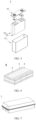
- FIG. 4 shows a secondary battery 5 of a rectangular structure as an example.
- the outer package may include a housing 51 and a cover plate 53.
- the housing 51 may include a base plate and a side plate connected onto the base plate, and the base plate and the side plate enclose an accommodating cavity.
- the housing 51 has an opening communicating with the accommodating cavity, and the cover plate 53 can cover the opening to close the accommodating cavity.
- the positive electrode plate, the negative electrode plate, and the separator may be made into an electrode assembly 52 through winding or lamination.
- the electrode assembly 52 is packaged in the accommodating cavity.
- the electrolyte infiltrates the electrode assembly 52.
- secondary batteries may be assembled into a battery module, and the battery module may include one or more secondary batteries.
- a specific quantity may be chosen by persons skilled in the art based on use and capacity of the battery module.
- FIG. 6 shows a battery module 4 as an example.
- a plurality of secondary batteries 5 may be sequentially arranged in a length direction of the battery module 4.
- the secondary batteries 5 may alternatively be arranged in any other manner.
- the plurality of secondary batteries 5 may be fastened through fasteners.
- the battery module 4 may further include a housing with an accommodating space, and the plurality of secondary batteries 5 are accommodated in the accommodating space.
- the battery module may be further assembled into a battery pack, and the battery pack may include one or more battery modules.
- a specific quantity may be chosen by persons skilled in the art based on use and capacity of the battery pack.
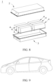
- FIG. 7 and FIG. 8 show a battery pack 1 as an example.
- the battery pack 1 may include a battery box and a plurality of battery modules 4 arranged in the battery box.
- the battery box includes an upper box body 2 and a lower box body 3.
- the upper box body 2 can cover the lower box body 3 to form an enclosed space for accommodating the battery module 4.
- the plurality of battery modules 4 may be arranged in the battery box in any manner.
- this application further provides an electric apparatus.
- the electric apparatus includes at least one of the secondary battery, the battery module, or the battery pack provided in this application.
- the secondary battery, the battery module, or the battery pack may be used as a power source for the electric apparatus, or an energy storage unit of the electric apparatus.
- the electric apparatus may include a mobile device (for example, a mobile phone or a notebook computer), an electric vehicle (for example, a battery electric vehicle, a hybrid electric vehicle, a plug-in hybrid electric vehicle, an electric bicycle, an electric scooter, an electric golf vehicle, or an electric truck), an electric train, a ship, a satellite system, an energy storage system, and the like, but is not limited thereto.
- the secondary battery, the battery module, or the battery pack may be selected for the electric apparatus based on requirements for using the electric apparatus.
- FIG. 9 shows an electric apparatus as an example.
- the electric apparatus is a battery electric vehicle, a hybrid electric vehicle, a plug-in hybrid electric vehicle, or the like.
- a battery pack or a battery module may be used.
- the apparatus may be a mobile phone, a tablet computer, a notebook computer, or the like.
- Such apparatus is generally required to be light and thin and may use a secondary battery as its power source.
- a copper layer was plated on a surface of a polymer matrix by using a physical vapor deposition (PVD) method to obtain a polyimide PVD base matrix; the polyimide PVD base matrix was used as a cathode, and a phosphorous copper was used as an anode, which were placed in an electroplating bath containing the copper plating solution for direct current electroplating.
- PVD physical vapor deposition
- Electroplating parameters are as follows:
- Example 1-1 Preparation of copper plating solution and negative electrode composite current collector basically followed that in Example 1-1 except that the moistening agent was replaced with polypropylene glycol having a number-average molecular weight of 10000.
- Example 1-1 Preparation of copper plating solution and negative electrode composite current collector basically followed that in Example 1-1 except that acetaldehyde and ethylene diamine tetraacetic acid were further added at a volume ratio of 2:1 as grain refiners, and a concentration of the grain refiners in the copper plating solution was 0.08 mL/L.
- Example 1-1 Preparation of copper plating solution and negative electrode composite current collector basically followed that in Example 1-1 except that acetaldehyde and ethylene diamine tetraacetic acid were further added at a volume ratio of 2:1 as grain refiners, and a concentration of the grain refiners in the copper plating solution was 0.01 mL/L.
- Example 1-1 Preparation of copper plating solution and negative electrode composite current collector basically followed that in Example 1-1 except that acetaldehyde and ethylene diamine tetraacetic acid were further added at a volume ratio of 2:1 as grain refiners, and a concentration of the grain refiners in the copper plating solution was 0.1 mL/L.
- Example 1-1 Preparation of copper plating solution and negative electrode composite current collector basically followed that in Example 1-1 except that ethylene diamine tetraacetic acid was further added as a grain refiner, and a concentration of the ethylene diamine tetraacetic acid in the copper plating solution was 0.12 mL/L.
- Test method for adhesion of metal layer a double-sided adhesive tape was pasted on a flat and smooth steel plate, and the composite current collector was cut into sections having the same width as the double-sided adhesive tape; the composite current collector was pasted flatly on a surface of the double-sided adhesive tape, and the double-sided adhesive tape on the surface was cut into sections with a same width as the composite current collector, which were attached to the surface of the composite current collector; an A4 paper strip larger than a length of the steel plate was attached at the head of the composite current collector, a 2.5kg roller was used to roll back and forth on the surface till the adhesive tape was flat, the steel plate was fastened to a tensile machine at one end, and the A4 paper strip together with the adhesive tape on the surface was fastened to the other end of the tensile machine; and the adhesive tape was peeled off at a speed of 500 mm/min to obtain a peeling force curve, and a mean peeling force was calculated.
- a current collector was cut into strips of 15 mm x 150 mm with a strip sampler, and strip samples that had been cut were tested using a tensile machine.
- the tensile machine had an initial spacing of 50 mm and was stretched at a constant rate of 50 mm/min till the sample was broken. A tensile strength was read directly from the tensile machine.
- a current collector was cut into strips of 15 mm x 150 mm with a strip sampler, and strip samples that had been cut were tested using a tensile machine.
- the tensile machine had an initial spacing of 50 mm and was stretched at a constant rate of 50 mm/min till the sample was broken.
- a tensile strength was read directly from the tensile machine.
- An elongation at break stretching distance/initial spacing x 100%, in other words, an elongation rate.
- the negative electrode composite current collectors obtained in the foregoing examples and comparative examples were separately prepared into secondary batteries as shown below for performance testing.
- a positive electrode plate (compaction density: 3.4 g/cm 3 ), a PP/PE/PP separator, and a negative electrode plate (compaction density: 1.6 g/cm 3 ) were wound together to form a bare battery cell, then the bare battery cell was placed into a battery housing, an electrolyte (an EC:EMC volume ratio was 3:7, and LiPF 6 was 1 mol/L) was injected, and then sealing, formation, and other processes were performed to finally obtain a lithium-ion battery.
- an electrolyte an EC:EMC volume ratio was 3:7, and LiPF 6 was 1 mol/L
- the lithium-ion batteries were subjected to cycle life test and a specific test method was as follows: The lithium-ion batteries were charged and discharged at 25°C, to be specific, first charged to 4.2 V at a current of 1 C, and then discharged to 2.8 V at a current of 1 C, and discharge capacities in the first cycle were recorded. The batteries were charged and discharged for 1000 cycles at 1 C/1 C, and discharge capacities in the 1000 th cycle were recorded. The discharge capacities in the 1000 th cycle were divided by the discharge capacities in the first cycle, respectively, to obtain capacity retention rates in the 1000 th cycle, and the numbers of battery cycles to 80% state of health were recorded.
- Example 1-1 to Example 1-5 when copper plating solutions contain the leveling agents having the structures, negative electrode composite current collectors prepared using the copper plating solutions have plating adhesion of greater than 2.3 N, tensile strength of greater than 186 MPa, and elongation of greater than 4.4%.
- the numbers of battery cycles of lithium-ion batteries containing negative electrode composite current collectors with 80% state of charge are greater than 2221, and capacity retention rates of the lithium-ion batteries after 1000 cycles are higher than 90.3%.
- Example 1-1 when leveling agents contained in copper plating solutions are 1-4 mL/L, plating adhesion, tensile strength, and elongation of negative electrode composite current collectors prepared using the copper plating solutions are further improved.
- Example 1-1 when copper plating solutions further contain grain refiners, plating adhesion, tensile strength, and elongation of negative electrode composite current collectors prepared using the copper plating solutions are further improved, thereby further improving cycling performance of lithium-ion batteries.
- grain refiners can further improve uniformity of copper layers obtained.
Landscapes
- Chemical & Material Sciences (AREA)
- Engineering & Computer Science (AREA)
- Chemical Kinetics & Catalysis (AREA)
- Electrochemistry (AREA)
- Materials Engineering (AREA)
- Metallurgy (AREA)
- Organic Chemistry (AREA)
- General Chemical & Material Sciences (AREA)
- Composite Materials (AREA)
- Electroplating And Plating Baths Therefor (AREA)
- Cell Electrode Carriers And Collectors (AREA)
- Manufacturing & Machinery (AREA)
Claims (11)
- Kupferplattierungslösung für einen Verbundwerkstoff-Stromabnehmer, gekennzeichnet durch Umfassen eines durch eine allgemeine Formel (1) dargestellten Verlaufmittels,
 wobei ein Anion X F-, Cl- oder Br- ist;R1 und R3 jeweils unabhängig ausgewählt sind aus O und S;R2 S ist; undR4, R5 und R6 jeweils unabhängig ausgewählt sind aus Wasserstoff, einem substituierten oder unsubstituierten Alkyl, einem substituierten oder unsubstituierten Vinyl, einem substituierten oder unsubstituierten Aryl und einem substituierten oder unsubstituierten Heteroaryl;wobei die Kupferplattierungslösung einen pH-Wert in dem Bereich von 0,5 bis 4 aufweist.
 - Kupferplattierungslösung gemäß Anspruch 1, dadurch gekennzeichnet, dass
R4, R5 und R6 jeweils unabhängig ausgewählt sind aus Wasserstoff, einem substituierten oder unsubstituierten Alkyl mit 1-6 Kohlenstoffatomen, einem substituierten oder unsubstituierten Vinyl mit 2-6 Kohlenstoffatomen und einem substituierten oder unsubstituierten Pyrimidyl. - Kupferplattierungslösung gemäß Anspruch 1 oder 2, dadurch gekennzeichnet, dass das Verlaufmittel

- Kupferplattierungslösung gemäß einem der Ansprüche 1 bis 3, gekennzeichnet durchferner Umfassen von Kupfersulfat, Schwefelsäure, Salzsäure, einem Aufheller, einem Feuchthaltemittel und entionisiertem Wasser;wobei der Aufheller eine Verbindung ist, die eine Disulfidbindung, eine Sulfonsäuregruppe oder ein Sulfhydryl enthält; undwobei das Feuchthaltemittel wenigstens eines von Polyethylenglycol und Polypropylenbglycol ist.
- Kupferplattierungslösung gemäß Anspruch 4, dadurch gekennzeichnet, dass
der Aufheller eines oder zwei von Bis(natriumsulfopropyl)disulfid und Natrium-3-mercaptopropansulfonat ist. - Kupferplattierungslösung gemäß Anspruch 5, dadurch gekennzeichnet, dass
das Polyethylenglycol ein anzahlgemitteltes Molekulargewicht von 4000-15000 aufweist und das Polypropylenglycol ein anzahlgemitteltes Molekulargewicht von 5000-20000 aufweist. - Kupferplattierungslösung gemäß einem der Ansprüche 1 bis 6, gekennzeichnet durchferner Umfassen eines Kornfeiners, wobeider Kornfeiner wenigstens eines von Acetaldehyd und Ethylendiamintetraessigsäure ist.
- Kupferplattierungslösung gemäß einem der Ansprüche 4 bis 7, dadurch gekennzeichnet, dass
jeder Liter der Kupferplattierungslösung 60-120 g/l Kupfersulfat, 80-110 ml/l 98 % Schwefelsäure, 40-90 ppm Salzsäure, gemessen als Chloridionen, 2-12 ml/l an dem Aufheller, 1-4 ml/l an dem Verlaufmittel, 0,5-2 ml/l an dem Feuchthaltemittel, 0,01-0,2 ml/l an dem Kornfeiner und als Rest entionisiertes Wasser enthält. - Verwendung der Kupferplattierungslösung gemäß einem der Ansprüche 1-8, dadurch gekennzeichnet, dass
ein anwendbarer Temperaturbereich der Kupferplattierungslösung 20-50 °C, gegebenenfalls 20-45 °C und weiter gegebenenfalls 20-35 °C beträgt. - Verwendung der Kupferplattierungslösung gemäß Anspruch 9, wobei ein anwendbarer Kathodenstromdichtebereich der Kupferplattierungslösung 1-20 A/dm2, gegebenenfalls 1-15 A/cm2 und weiter gegebenenfalls 1-10 A/dm2 beträgt;
und/oder wobei
ein anwendbarer Anodenstromdichtebereich der Kupferplattierungslösung 0,5-3 A/dm2 beträgt. - Verfahren zur Herstellung eines Negativelektroden-Verbundwerkstoff-Stromabnehmers, wobei der Negativelektroden-Verbundwerkstoff-Stromabnehmer eine Polymermatrix und Kupferschichten, die auf zwei Oberflächen der Polymermatrix gebildet sind, umfasst, wobei die Kupferschicht durch Elektroplattieren unter Verwendung der Kupferplattierungslösung gemäß einem der Ansprüche 1 bis 8 erhalten wird.
Applications Claiming Priority (1)
| Application Number | Priority Date | Filing Date | Title |
|---|---|---|---|
| PCT/CN2021/126433 WO2023070319A1 (zh) | 2021-10-26 | 2021-10-26 | 一种镀铜镀液及由其制备的负极复合集流体 |
Publications (5)
| Publication Number | Publication Date |
|---|---|
| EP4194589A4 EP4194589A4 (de) | 2023-06-14 |
| EP4194589A1 EP4194589A1 (de) | 2023-06-14 |
| EP4194589C0 EP4194589C0 (de) | 2024-09-18 |
| EP4194589B1 true EP4194589B1 (de) | 2024-09-18 |
| EP4194589B8 EP4194589B8 (de) | 2024-10-23 |
Family
ID=86056135
Family Applications (1)
| Application Number | Title | Priority Date | Filing Date |
|---|---|---|---|
| EP21928341.3A Active EP4194589B8 (de) | 2021-10-26 | 2021-10-26 | Kupferplattierungslösung und damit hergestellter zusammengesetzter stromabnehmer mit negativer elektrode |
Country Status (6)
| Country | Link |
|---|---|
| US (2) | US11932959B2 (de) |
| EP (1) | EP4194589B8 (de) |
| JP (1) | JP7477707B2 (de) |
| KR (1) | KR102685817B1 (de) |
| CN (1) | CN116348636B (de) |
| WO (1) | WO2023070319A1 (de) |
Families Citing this family (3)
| Publication number | Priority date | Publication date | Assignee | Title |
|---|---|---|---|---|
| CN119900058A (zh) * | 2023-10-27 | 2025-04-29 | 江阴纳力新材料科技有限公司 | 一种镀铜液、包括其的金属铜层及其应用 |
| CN119980427A (zh) * | 2023-11-13 | 2025-05-13 | 宁德时代新能源科技股份有限公司 | 电镀液复合添加剂、电镀液和电解铜箔及其应用 |
| CN120006266B (zh) * | 2025-02-14 | 2025-11-25 | 哈尔滨工业大学 | 一种具有功能离子自释放特性的柔性三维集流体的制备方法及其应用 |
Family Cites Families (29)
| Publication number | Priority date | Publication date | Assignee | Title |
|---|---|---|---|---|
| US3018232A (en) * | 1958-06-05 | 1962-01-23 | Westinghouse Electric Corp | Addition agent for cyanide plating baths |
| US2997428A (en) * | 1958-10-30 | 1961-08-22 | Westinghouse Electric Corp | Addition agent for acid copper electrolytes |
| US2972572A (en) * | 1958-12-09 | 1961-02-21 | Westinghouse Electric Corp | Acid copper addition agent |
| DE2360892A1 (de) * | 1972-12-14 | 1974-06-20 | M & T Chemicals Inc | Waessriges saures galvanisches kupferbad |
| US4347108A (en) * | 1981-05-29 | 1982-08-31 | Rohco, Inc. | Electrodeposition of copper, acidic copper electroplating baths and additives therefor |
| JPS61253376A (ja) * | 1985-05-01 | 1986-11-11 | Shinko Electric Ind Co Ltd | 銅又は銅合金材の電解金めっき用前処理液 |
| US7384533B2 (en) * | 2001-07-24 | 2008-06-10 | 3M Innovative Properties Company | Electrolytic processes with reduced cell voltage and gas formation |
| JP4039893B2 (ja) | 2002-06-19 | 2008-01-30 | 東洋鋼鈑株式会社 | 高容量負極 |
| JP2004295012A (ja) * | 2003-03-28 | 2004-10-21 | Fuji Photo Film Co Ltd | 感光性組成物 |
| CN101092724A (zh) * | 2007-07-13 | 2007-12-26 | 福州大学 | 用于镀银的无氰型电镀液 |
| JP2010082844A (ja) * | 2008-09-29 | 2010-04-15 | Fujifilm Corp | 平版印刷版原版、およびその製版方法 |
| CN103924268B (zh) * | 2013-12-26 | 2016-04-13 | 苏州昕皓新材料科技有限公司 | 一种酸铜整平剂的应用 |
| US9551081B2 (en) * | 2013-12-26 | 2017-01-24 | Shinhao Materials LLC | Leveling composition and method for electrodeposition of metals in microelectronics |
| CN104073845A (zh) * | 2014-06-11 | 2014-10-01 | 安徽长青电子机械(集团)有限公司 | 一种pcb板镀金的方法 |
| CN105350043B (zh) * | 2015-11-13 | 2018-08-28 | 华南师范大学 | 一种金属电镀法制备金属网络透明导电电极的方法 |
| CN105316715B (zh) * | 2015-12-09 | 2018-02-02 | 上海新阳半导体材料股份有限公司 | 一种电镀铜用抑制剂及其用途 |
| KR102180926B1 (ko) * | 2017-06-28 | 2020-11-19 | 에스케이넥실리스 주식회사 | 우수한 작업성 및 충방전 특성을 갖는 동박, 그것을 포함하는 전극, 그것을 포함하는 이차전지, 및 그것의 제조방법 |
| CN107217283B (zh) * | 2017-07-25 | 2018-11-16 | 上海新阳半导体材料股份有限公司 | 整平剂、含其的金属电镀组合物、制备方法及应用 |
| CN107641822B (zh) * | 2017-09-28 | 2019-08-09 | 永星化工(上海)有限公司 | 电镀铜用高填平酸铜光亮剂 |
| CN107858716A (zh) * | 2017-12-22 | 2018-03-30 | 广州美迪斯新材料有限公司 | 用于电镀液的添加剂 |
| CN110943227B (zh) * | 2019-05-31 | 2021-03-09 | 宁德时代新能源科技股份有限公司 | 复合集流体、电极极片及电化学装置 |
| US11508969B2 (en) * | 2019-08-20 | 2022-11-22 | Graphenix Development, Inc. | Structured anodes for lithium-based energy storage devices |
| CN110373687A (zh) | 2019-08-30 | 2019-10-25 | 广州皓悦新材料科技有限公司 | 一种可镀高纵横比通孔和盲孔的脉冲电镀光剂及其制备方法 |
| US11512406B2 (en) * | 2019-10-17 | 2022-11-29 | Rohm And Haas Electronic Materials Llc | Method of enhancing copper electroplating |
| CN111088509A (zh) | 2020-01-17 | 2020-05-01 | 浙江金欣新材料科技股份有限公司 | 一种酸性镀铜添加剂及其制备方法 |
| CN111962108A (zh) | 2020-07-08 | 2020-11-20 | 重庆金美新材料科技有限公司 | 一种铜电镀液 |
| CN111793810A (zh) | 2020-07-22 | 2020-10-20 | 六安市金安区宝德龙科技创新有限公司 | 一种微酸性镀液光亮镀铜用光亮剂及其制备方法 |
| CN112899736A (zh) | 2021-01-15 | 2021-06-04 | 深圳中科利尔科技有限公司 | 一种pcb高纵横通孔电镀铜添加剂及其制备方法 |
| CN113061947A (zh) | 2021-03-20 | 2021-07-02 | 深圳市创智成功科技有限公司 | 一种应用于5g陶瓷基板的通孔铜填充电镀配方及电镀流程 |
-
2021
- 2021-10-26 EP EP21928341.3A patent/EP4194589B8/de active Active
- 2021-10-26 JP JP2023502963A patent/JP7477707B2/ja active Active
- 2021-10-26 CN CN202180007555.7A patent/CN116348636B/zh active Active
- 2021-10-26 KR KR1020237001516A patent/KR102685817B1/ko active Active
- 2021-10-26 WO PCT/CN2021/126433 patent/WO2023070319A1/zh not_active Ceased
-
2022
- 2022-09-01 US US17/901,101 patent/US11932959B2/en active Active
-
2023
- 2023-12-14 US US18/540,081 patent/US12467155B2/en active Active
Also Published As
| Publication number | Publication date |
|---|---|
| EP4194589B8 (de) | 2024-10-23 |
| WO2023070319A1 (zh) | 2023-05-04 |
| CN116348636A (zh) | 2023-06-27 |
| KR102685817B1 (ko) | 2024-07-17 |
| EP4194589C0 (de) | 2024-09-18 |
| US20240141532A1 (en) | 2024-05-02 |
| EP4194589A4 (de) | 2023-06-14 |
| EP4194589A1 (de) | 2023-06-14 |
| JP2023547583A (ja) | 2023-11-13 |
| US11932959B2 (en) | 2024-03-19 |
| US20230132206A1 (en) | 2023-04-27 |
| JP7477707B2 (ja) | 2024-05-01 |
| CN116348636B (zh) | 2026-03-03 |
| KR20230062536A (ko) | 2023-05-09 |
| US12467155B2 (en) | 2025-11-11 |
Similar Documents
| Publication | Publication Date | Title |
|---|---|---|
| EP3993110B1 (de) | Elektrodenfolie, elektrochemische vorrichtung und vorrichtung dafür | |
| US12467155B2 (en) | Copper plating solution and negative electrode composite current collector prepared using same | |
| US20230082055A1 (en) | Metal foil and preparation method thereof, current collector, electrode, battery, and electrical device | |
| JP7622220B6 (ja) | 電解銅箔及びその製造方法、負極板、二次電池、電池モジュール、電池パック並びに電力消費装置 | |
| EP3951988B1 (de) | Elektrolyt und lithium-metall-batterie diesen elektrolyten umfassend, batteriemodul, batteriepack und vorrichtung | |
| US20240170641A1 (en) | Secondary battery and battery module, battery pack, and electric apparatus containing such secondary battery | |
| EP4693686A1 (de) | Separator und herstellungsverfahren dafür, batterie und elektrische vorrichtung | |
| US20250239653A1 (en) | Electrolyte, battery, and electric apparatus | |
| EP4664653A1 (de) | Verbundseparator, sekundärbatterie und elektrische vorrichtung | |
| EP4517906A1 (de) | Sekundärbatterie und herstellungsverfahren dafür sowie elektrische vorrichtung damit | |
| EP4207389A1 (de) | Positivelektrodenaufschlämmung, positivelektrodenplatte, lithium-ionen-batterie, batteriemodul, batteriepack und elektrische vorrichtung | |
| EP4276936A1 (de) | Lithium-ionen-batterie, batteriemodul, batteriepack und elektrische vorrichtung | |
| EP4318637A1 (de) | Sekundärbatterie und herstellungsverfahren dafür, batteriemodul, batteriepack und elektrische vorrichtung | |
| EP4318726A1 (de) | Sekundärbatterie und herstellungsverfahren dafür sowie batteriemodul, batteriepack und elektrische vorrichtung | |
| CN117015883B (zh) | 电池、其制备方法、及包含其的用电装置 | |
| EP4629425A1 (de) | Separator und herstellungsverfahren dafür, lithium-ionen-batterie und elektrische vorrichtung | |
| CN111009687A (zh) | 一种非水电解液和锂离子电池 | |
| US20240178448A1 (en) | Electrolyte solution and lithium-ion battery comprising same | |
| WO2026055930A1 (zh) | 新型电解铜箔及其制备方法、负极极片和二次电池 | |
| CN121583995A (zh) | 一种钠离子电池单体、电池装置和用电装置 | |
| CN119361716A (zh) | 新型电解铜箔及其制备方法、负极极片和二次电池 | |
| CN117276468A (zh) | 负极极片、电池和用电装置 | |
| CN120033334A (zh) | 一种锂二次电池和用电装置 | |
| CN118668261A (zh) | 合金箔及其制备方法、集流体、电极、二次电池和用电装置 | |
| CN118668101A (zh) | 合金箔及其制备方法、集流体、负极极片、二次电池和用电装置 |
Legal Events
| Date | Code | Title | Description |
|---|---|---|---|
| STAA | Information on the status of an ep patent application or granted ep patent |
Free format text: STATUS: UNKNOWN |
|
| STAA | Information on the status of an ep patent application or granted ep patent |
Free format text: STATUS: THE INTERNATIONAL PUBLICATION HAS BEEN MADE |
|
| PUAI | Public reference made under article 153(3) epc to a published international application that has entered the european phase |
Free format text: ORIGINAL CODE: 0009012 |
|
| STAA | Information on the status of an ep patent application or granted ep patent |
Free format text: STATUS: REQUEST FOR EXAMINATION WAS MADE |
|
| 17P | Request for examination filed |
Effective date: 20220905 |
|
| A4 | Supplementary search report drawn up and despatched |
Effective date: 20230425 |
|
| AK | Designated contracting states |
Kind code of ref document: A1 Designated state(s): AL AT BE BG CH CY CZ DE DK EE ES FI FR GB GR HR HU IE IS IT LI LT LU LV MC MK MT NL NO PL PT RO RS SE SI SK SM TR |
|
| STAA | Information on the status of an ep patent application or granted ep patent |
Free format text: STATUS: EXAMINATION IS IN PROGRESS |
|
| 17Q | First examination report despatched |
Effective date: 20230927 |
|
| RIC1 | Information provided on ipc code assigned before grant |
Ipc: H01M 4/02 20060101ALN20240126BHEP Ipc: C25D 17/10 20060101ALN20240126BHEP Ipc: H01M 4/66 20060101ALI20240126BHEP Ipc: C25D 7/00 20060101ALI20240126BHEP Ipc: C25D 7/06 20060101ALI20240126BHEP Ipc: C25D 5/56 20060101ALI20240126BHEP Ipc: C25D 3/38 20060101AFI20240126BHEP |
|
| GRAP | Despatch of communication of intention to grant a patent |
Free format text: ORIGINAL CODE: EPIDOSNIGR1 |
|
| STAA | Information on the status of an ep patent application or granted ep patent |
Free format text: STATUS: GRANT OF PATENT IS INTENDED |
|
| INTG | Intention to grant announced |
Effective date: 20240312 |
|
| GRAS | Grant fee paid |
Free format text: ORIGINAL CODE: EPIDOSNIGR3 |
|
| RAP3 | Party data changed (applicant data changed or rights of an application transferred) |
Owner name: CONTEMPORARY AMPEREX TECHNOLOGY CO., LIMITED |
|
| GRAA | (expected) grant |
Free format text: ORIGINAL CODE: 0009210 |
|
| STAA | Information on the status of an ep patent application or granted ep patent |
Free format text: STATUS: THE PATENT HAS BEEN GRANTED |
|
| GRAT | Correction requested after decision to grant or after decision to maintain patent in amended form |
Free format text: ORIGINAL CODE: EPIDOSNCDEC |
|
| REG | Reference to a national code |
Ref country code: DE Ref legal event code: R081 Ref document number: 602021019128 Country of ref document: DE Owner name: CONTEMPORARY AMPEREX TECHNOLOGY (HONG KONG) LI, HK Free format text: FORMER OWNER: CONTEMPORARY AMPEREX TECHNOLOGY CO., LIMITED, NINGDE CITY, FUJIAN, CN |
|
| AK | Designated contracting states |
Kind code of ref document: B1 Designated state(s): AL AT BE BG CH CY CZ DE DK EE ES FI FR GB GR HR HU IE IS IT LI LT LU LV MC MK MT NL NO PL PT RO RS SE SI SK SM TR |
|
| DAV | Request for validation of the european patent (deleted) | ||
| DAX | Request for extension of the european patent (deleted) | ||
| REG | Reference to a national code |
Ref country code: GB Ref legal event code: FG4D |
|
| REG | Reference to a national code |
Ref country code: CH Ref legal event code: PK Free format text: BERICHTIGUNG B8 Ref country code: CH Ref legal event code: EP |
|
| RAP2 | Party data changed (patent owner data changed or rights of a patent transferred) |
Owner name: CONTEMPORARY AMPEREX TECHNOLOGY(HONG KONG) LIMITED |
|
| REG | Reference to a national code |
Ref country code: IE Ref legal event code: FG4D |
|
| REG | Reference to a national code |
Ref country code: DE Ref legal event code: R096 Ref document number: 602021019128 Country of ref document: DE |
|
| U01 | Request for unitary effect filed |
Effective date: 20241014 |
|
| U07 | Unitary effect registered |
Designated state(s): AT BE BG DE DK EE FI FR IT LT LU LV MT NL PT RO SE SI Effective date: 20241031 |
|
| U20 | Renewal fee for the european patent with unitary effect paid |
Year of fee payment: 4 Effective date: 20241122 |
|
| PG25 | Lapsed in a contracting state [announced via postgrant information from national office to epo] |
Ref country code: NO Free format text: LAPSE BECAUSE OF FAILURE TO SUBMIT A TRANSLATION OF THE DESCRIPTION OR TO PAY THE FEE WITHIN THE PRESCRIBED TIME-LIMIT Effective date: 20241218 |
|
| PG25 | Lapsed in a contracting state [announced via postgrant information from national office to epo] |
Ref country code: GR Free format text: LAPSE BECAUSE OF FAILURE TO SUBMIT A TRANSLATION OF THE DESCRIPTION OR TO PAY THE FEE WITHIN THE PRESCRIBED TIME-LIMIT Effective date: 20241219 |
|
| PG25 | Lapsed in a contracting state [announced via postgrant information from national office to epo] |
Ref country code: HR Free format text: LAPSE BECAUSE OF FAILURE TO SUBMIT A TRANSLATION OF THE DESCRIPTION OR TO PAY THE FEE WITHIN THE PRESCRIBED TIME-LIMIT Effective date: 20240918 |
|
| PG25 | Lapsed in a contracting state [announced via postgrant information from national office to epo] |
Ref country code: RS Free format text: LAPSE BECAUSE OF FAILURE TO SUBMIT A TRANSLATION OF THE DESCRIPTION OR TO PAY THE FEE WITHIN THE PRESCRIBED TIME-LIMIT Effective date: 20241218 |
|
| PG25 | Lapsed in a contracting state [announced via postgrant information from national office to epo] |
Ref country code: RS Free format text: LAPSE BECAUSE OF FAILURE TO SUBMIT A TRANSLATION OF THE DESCRIPTION OR TO PAY THE FEE WITHIN THE PRESCRIBED TIME-LIMIT Effective date: 20241218 Ref country code: NO Free format text: LAPSE BECAUSE OF FAILURE TO SUBMIT A TRANSLATION OF THE DESCRIPTION OR TO PAY THE FEE WITHIN THE PRESCRIBED TIME-LIMIT Effective date: 20241218 Ref country code: HR Free format text: LAPSE BECAUSE OF FAILURE TO SUBMIT A TRANSLATION OF THE DESCRIPTION OR TO PAY THE FEE WITHIN THE PRESCRIBED TIME-LIMIT Effective date: 20240918 Ref country code: GR Free format text: LAPSE BECAUSE OF FAILURE TO SUBMIT A TRANSLATION OF THE DESCRIPTION OR TO PAY THE FEE WITHIN THE PRESCRIBED TIME-LIMIT Effective date: 20241219 |
|
| PG25 | Lapsed in a contracting state [announced via postgrant information from national office to epo] |
Ref country code: IS Free format text: LAPSE BECAUSE OF FAILURE TO SUBMIT A TRANSLATION OF THE DESCRIPTION OR TO PAY THE FEE WITHIN THE PRESCRIBED TIME-LIMIT Effective date: 20250118 |
|
| PG25 | Lapsed in a contracting state [announced via postgrant information from national office to epo] |
Ref country code: SM Free format text: LAPSE BECAUSE OF FAILURE TO SUBMIT A TRANSLATION OF THE DESCRIPTION OR TO PAY THE FEE WITHIN THE PRESCRIBED TIME-LIMIT Effective date: 20240918 |
|
| PG25 | Lapsed in a contracting state [announced via postgrant information from national office to epo] |
Ref country code: ES Free format text: LAPSE BECAUSE OF FAILURE TO SUBMIT A TRANSLATION OF THE DESCRIPTION OR TO PAY THE FEE WITHIN THE PRESCRIBED TIME-LIMIT Effective date: 20240918 |
|
| PG25 | Lapsed in a contracting state [announced via postgrant information from national office to epo] |
Ref country code: PL Free format text: LAPSE BECAUSE OF FAILURE TO SUBMIT A TRANSLATION OF THE DESCRIPTION OR TO PAY THE FEE WITHIN THE PRESCRIBED TIME-LIMIT Effective date: 20240918 Ref country code: CZ Free format text: LAPSE BECAUSE OF FAILURE TO SUBMIT A TRANSLATION OF THE DESCRIPTION OR TO PAY THE FEE WITHIN THE PRESCRIBED TIME-LIMIT Effective date: 20240918 |
|
| PG25 | Lapsed in a contracting state [announced via postgrant information from national office to epo] |
Ref country code: SK Free format text: LAPSE BECAUSE OF FAILURE TO SUBMIT A TRANSLATION OF THE DESCRIPTION OR TO PAY THE FEE WITHIN THE PRESCRIBED TIME-LIMIT Effective date: 20240918 |
|
| REG | Reference to a national code |
Ref country code: CH Ref legal event code: PL |
|
| PG25 | Lapsed in a contracting state [announced via postgrant information from national office to epo] |
Ref country code: MC Free format text: LAPSE BECAUSE OF FAILURE TO SUBMIT A TRANSLATION OF THE DESCRIPTION OR TO PAY THE FEE WITHIN THE PRESCRIBED TIME-LIMIT Effective date: 20240918 |
|
| PG25 | Lapsed in a contracting state [announced via postgrant information from national office to epo] |
Ref country code: CH Free format text: LAPSE BECAUSE OF NON-PAYMENT OF DUE FEES Effective date: 20241031 |
|
| PLBE | No opposition filed within time limit |
Free format text: ORIGINAL CODE: 0009261 |
|
| STAA | Information on the status of an ep patent application or granted ep patent |
Free format text: STATUS: NO OPPOSITION FILED WITHIN TIME LIMIT |
|
| 26N | No opposition filed |
Effective date: 20250619 |
|
| PG25 | Lapsed in a contracting state [announced via postgrant information from national office to epo] |
Ref country code: IE Free format text: LAPSE BECAUSE OF NON-PAYMENT OF DUE FEES Effective date: 20241026 |
|
| U20 | Renewal fee for the european patent with unitary effect paid |
Year of fee payment: 5 Effective date: 20251021 |
|
| PGFP | Annual fee paid to national office [announced via postgrant information from national office to epo] |
Ref country code: GB Payment date: 20251024 Year of fee payment: 5 |
|
| PG25 | Lapsed in a contracting state [announced via postgrant information from national office to epo] |
Ref country code: CY Free format text: LAPSE BECAUSE OF FAILURE TO SUBMIT A TRANSLATION OF THE DESCRIPTION OR TO PAY THE FEE WITHIN THE PRESCRIBED TIME-LIMIT; INVALID AB INITIO Effective date: 20211026 |
|
| PG25 | Lapsed in a contracting state [announced via postgrant information from national office to epo] |
Ref country code: HU Free format text: LAPSE BECAUSE OF FAILURE TO SUBMIT A TRANSLATION OF THE DESCRIPTION OR TO PAY THE FEE WITHIN THE PRESCRIBED TIME-LIMIT; INVALID AB INITIO Effective date: 20211026 |