EP4190928A1 - Negativelektrodenverbundkörper und sekundärbatterie - Google Patents
Negativelektrodenverbundkörper und sekundärbatterie Download PDFInfo
- Publication number
- EP4190928A1 EP4190928A1 EP21851947.8A EP21851947A EP4190928A1 EP 4190928 A1 EP4190928 A1 EP 4190928A1 EP 21851947 A EP21851947 A EP 21851947A EP 4190928 A1 EP4190928 A1 EP 4190928A1
- Authority
- EP
- European Patent Office
- Prior art keywords
- negative electrode
- electrode composite
- active material
- layer
- composite according
- Prior art date
- Legal status (The legal status is an assumption and is not a legal conclusion. Google has not performed a legal analysis and makes no representation as to the accuracy of the status listed.)
- Pending
Links
Images


Classifications
-
- C—CHEMISTRY; METALLURGY
- C22—METALLURGY; FERROUS OR NON-FERROUS ALLOYS; TREATMENT OF ALLOYS OR NON-FERROUS METALS
- C22C—ALLOYS
- C22C18/00—Alloys based on zinc
- C22C18/04—Alloys based on zinc with aluminium as the next major constituent
-
- H—ELECTRICITY
- H01—ELECTRIC ELEMENTS
- H01M—PROCESSES OR MEANS, e.g. BATTERIES, FOR THE DIRECT CONVERSION OF CHEMICAL ENERGY INTO ELECTRICAL ENERGY
- H01M4/00—Electrodes
- H01M4/02—Electrodes composed of, or comprising, active material
- H01M4/36—Selection of substances as active materials, active masses, active liquids
- H01M4/38—Selection of substances as active materials, active masses, active liquids of elements or alloys
- H01M4/381—Alkaline or alkaline earth metals elements
- H01M4/382—Lithium
-
- C—CHEMISTRY; METALLURGY
- C22—METALLURGY; FERROUS OR NON-FERROUS ALLOYS; TREATMENT OF ALLOYS OR NON-FERROUS METALS
- C22C—ALLOYS
- C22C21/00—Alloys based on aluminium
-
- C—CHEMISTRY; METALLURGY
- C22—METALLURGY; FERROUS OR NON-FERROUS ALLOYS; TREATMENT OF ALLOYS OR NON-FERROUS METALS
- C22C—ALLOYS
- C22C24/00—Alloys based on an alkali or an alkaline earth metal
-
- H—ELECTRICITY
- H01—ELECTRIC ELEMENTS
- H01M—PROCESSES OR MEANS, e.g. BATTERIES, FOR THE DIRECT CONVERSION OF CHEMICAL ENERGY INTO ELECTRICAL ENERGY
- H01M10/00—Secondary cells; Manufacture thereof
- H01M10/05—Accumulators with non-aqueous electrolyte
- H01M10/052—Li-accumulators
-
- H—ELECTRICITY
- H01—ELECTRIC ELEMENTS
- H01M—PROCESSES OR MEANS, e.g. BATTERIES, FOR THE DIRECT CONVERSION OF CHEMICAL ENERGY INTO ELECTRICAL ENERGY
- H01M10/00—Secondary cells; Manufacture thereof
- H01M10/05—Accumulators with non-aqueous electrolyte
- H01M10/052—Li-accumulators
- H01M10/0525—Rocking-chair batteries, i.e. batteries with lithium insertion or intercalation in both electrodes; Lithium-ion batteries
-
- H—ELECTRICITY
- H01—ELECTRIC ELEMENTS
- H01M—PROCESSES OR MEANS, e.g. BATTERIES, FOR THE DIRECT CONVERSION OF CHEMICAL ENERGY INTO ELECTRICAL ENERGY
- H01M10/00—Secondary cells; Manufacture thereof
- H01M10/05—Accumulators with non-aqueous electrolyte
- H01M10/056—Accumulators with non-aqueous electrolyte characterised by the materials used as electrolytes, e.g. mixed inorganic/organic electrolytes
- H01M10/0561—Accumulators with non-aqueous electrolyte characterised by the materials used as electrolytes, e.g. mixed inorganic/organic electrolytes the electrolyte being constituted of inorganic materials only
- H01M10/0562—Solid materials
-
- H—ELECTRICITY
- H01—ELECTRIC ELEMENTS
- H01M—PROCESSES OR MEANS, e.g. BATTERIES, FOR THE DIRECT CONVERSION OF CHEMICAL ENERGY INTO ELECTRICAL ENERGY
- H01M10/00—Secondary cells; Manufacture thereof
- H01M10/42—Methods or arrangements for servicing or maintenance of secondary cells or secondary half-cells
- H01M10/4235—Safety or regulating additives or arrangements in electrodes, separators or electrolyte
-
- H—ELECTRICITY
- H01—ELECTRIC ELEMENTS
- H01M—PROCESSES OR MEANS, e.g. BATTERIES, FOR THE DIRECT CONVERSION OF CHEMICAL ENERGY INTO ELECTRICAL ENERGY
- H01M4/00—Electrodes
- H01M4/02—Electrodes composed of, or comprising, active material
- H01M4/13—Electrodes for accumulators with non-aqueous electrolyte, e.g. for lithium-accumulators; Processes of manufacture thereof
- H01M4/134—Electrodes based on metals, Si or alloys
-
- H—ELECTRICITY
- H01—ELECTRIC ELEMENTS
- H01M—PROCESSES OR MEANS, e.g. BATTERIES, FOR THE DIRECT CONVERSION OF CHEMICAL ENERGY INTO ELECTRICAL ENERGY
- H01M4/00—Electrodes
- H01M4/02—Electrodes composed of, or comprising, active material
- H01M4/36—Selection of substances as active materials, active masses, active liquids
- H01M4/38—Selection of substances as active materials, active masses, active liquids of elements or alloys
- H01M4/386—Silicon or alloys based on silicon
-
- H—ELECTRICITY
- H01—ELECTRIC ELEMENTS
- H01M—PROCESSES OR MEANS, e.g. BATTERIES, FOR THE DIRECT CONVERSION OF CHEMICAL ENERGY INTO ELECTRICAL ENERGY
- H01M4/00—Electrodes
- H01M4/02—Electrodes composed of, or comprising, active material
- H01M4/36—Selection of substances as active materials, active masses, active liquids
- H01M4/38—Selection of substances as active materials, active masses, active liquids of elements or alloys
- H01M4/387—Tin or alloys based on tin
-
- H—ELECTRICITY
- H01—ELECTRIC ELEMENTS
- H01M—PROCESSES OR MEANS, e.g. BATTERIES, FOR THE DIRECT CONVERSION OF CHEMICAL ENERGY INTO ELECTRICAL ENERGY
- H01M4/00—Electrodes
- H01M4/02—Electrodes composed of, or comprising, active material
- H01M4/36—Selection of substances as active materials, active masses, active liquids
- H01M4/38—Selection of substances as active materials, active masses, active liquids of elements or alloys
- H01M4/40—Alloys based on alkali metals
- H01M4/405—Alloys based on lithium
-
- H—ELECTRICITY
- H01—ELECTRIC ELEMENTS
- H01M—PROCESSES OR MEANS, e.g. BATTERIES, FOR THE DIRECT CONVERSION OF CHEMICAL ENERGY INTO ELECTRICAL ENERGY
- H01M4/00—Electrodes
- H01M4/02—Electrodes composed of, or comprising, active material
- H01M4/36—Selection of substances as active materials, active masses, active liquids
- H01M4/38—Selection of substances as active materials, active masses, active liquids of elements or alloys
- H01M4/42—Alloys based on zinc
-
- H—ELECTRICITY
- H01—ELECTRIC ELEMENTS
- H01M—PROCESSES OR MEANS, e.g. BATTERIES, FOR THE DIRECT CONVERSION OF CHEMICAL ENERGY INTO ELECTRICAL ENERGY
- H01M4/00—Electrodes
- H01M4/02—Electrodes composed of, or comprising, active material
- H01M4/36—Selection of substances as active materials, active masses, active liquids
- H01M4/38—Selection of substances as active materials, active masses, active liquids of elements or alloys
- H01M4/46—Alloys based on magnesium or aluminium
- H01M4/463—Aluminium based
-
- H—ELECTRICITY
- H01—ELECTRIC ELEMENTS
- H01M—PROCESSES OR MEANS, e.g. BATTERIES, FOR THE DIRECT CONVERSION OF CHEMICAL ENERGY INTO ELECTRICAL ENERGY
- H01M4/00—Electrodes
- H01M4/02—Electrodes composed of, or comprising, active material
- H01M4/36—Selection of substances as active materials, active masses, active liquids
- H01M4/38—Selection of substances as active materials, active masses, active liquids of elements or alloys
- H01M4/46—Alloys based on magnesium or aluminium
- H01M4/466—Magnesium based
-
- H—ELECTRICITY
- H01—ELECTRIC ELEMENTS
- H01M—PROCESSES OR MEANS, e.g. BATTERIES, FOR THE DIRECT CONVERSION OF CHEMICAL ENERGY INTO ELECTRICAL ENERGY
- H01M4/00—Electrodes
- H01M4/02—Electrodes composed of, or comprising, active material
- H01M4/62—Selection of inactive substances as ingredients for active masses, e.g. binders, fillers
-
- H—ELECTRICITY
- H01—ELECTRIC ELEMENTS
- H01M—PROCESSES OR MEANS, e.g. BATTERIES, FOR THE DIRECT CONVERSION OF CHEMICAL ENERGY INTO ELECTRICAL ENERGY
- H01M4/00—Electrodes
- H01M4/02—Electrodes composed of, or comprising, active material
- H01M2004/021—Physical characteristics, e.g. porosity, surface area
-
- H—ELECTRICITY
- H01—ELECTRIC ELEMENTS
- H01M—PROCESSES OR MEANS, e.g. BATTERIES, FOR THE DIRECT CONVERSION OF CHEMICAL ENERGY INTO ELECTRICAL ENERGY
- H01M4/00—Electrodes
- H01M4/02—Electrodes composed of, or comprising, active material
- H01M2004/026—Electrodes composed of, or comprising, active material characterised by the polarity
- H01M2004/027—Negative electrodes
-
- Y—GENERAL TAGGING OF NEW TECHNOLOGICAL DEVELOPMENTS; GENERAL TAGGING OF CROSS-SECTIONAL TECHNOLOGIES SPANNING OVER SEVERAL SECTIONS OF THE IPC; TECHNICAL SUBJECTS COVERED BY FORMER USPC CROSS-REFERENCE ART COLLECTIONS [XRACs] AND DIGESTS
- Y02—TECHNOLOGIES OR APPLICATIONS FOR MITIGATION OR ADAPTATION AGAINST CLIMATE CHANGE
- Y02E—REDUCTION OF GREENHOUSE GAS [GHG] EMISSIONS, RELATED TO ENERGY GENERATION, TRANSMISSION OR DISTRIBUTION
- Y02E60/00—Enabling technologies; Technologies with a potential or indirect contribution to GHG emissions mitigation
- Y02E60/10—Energy storage using batteries
-
- Y—GENERAL TAGGING OF NEW TECHNOLOGICAL DEVELOPMENTS; GENERAL TAGGING OF CROSS-SECTIONAL TECHNOLOGIES SPANNING OVER SEVERAL SECTIONS OF THE IPC; TECHNICAL SUBJECTS COVERED BY FORMER USPC CROSS-REFERENCE ART COLLECTIONS [XRACs] AND DIGESTS
- Y02—TECHNOLOGIES OR APPLICATIONS FOR MITIGATION OR ADAPTATION AGAINST CLIMATE CHANGE
- Y02P—CLIMATE CHANGE MITIGATION TECHNOLOGIES IN THE PRODUCTION OR PROCESSING OF GOODS
- Y02P70/00—Climate change mitigation technologies in the production process for final industrial or consumer products
- Y02P70/50—Manufacturing or production processes characterised by the final manufactured product
Definitions
- the present invention relates to a negative electrode composite and a secondary battery. More specifically, the present invention relates to a negative electrode composite including: a negative electrode active material containing Li and an element M that is solid soluble in Li as main components; and a substance X having a higher redox potential than the negative electrode active material or having no electrode activity, and a secondary battery including the negative electrode composite.
- lithium-ion secondary batteries for storing electric power in vehicles, such as electric vehicles and hybrid vehicles, and power generation devices, such as solar batteries and wind power generators.
- lithium-ion secondary batteries are widely used as power sources for mobile phones and small devices, and are also candidates for power sources for electric vehicles. However, they have lower energy density when compared to gasoline-powered vehicles, and even higher energy density is required to achieve an equivalent cruising range.
- Patent Literature 1 a negative electrode material in which a scaly fine powder of Si is mixed with carbon is disclosed (Patent Literature 1).
- Patent Literature 2 a negative electrode for a non-aqueous secondary battery having an intermetallic compound capable of absorbing and desorbing Li as an active material layer on a Cu or Cu alloy current collector is disclosed (Patent Literature 2).
- a negative electrode in which a thin film layer containing a metal that is not alloyed with Li and a thin film layer containing a metal element or a compound of a metal element that can be alloyed with Li are alternately stacked in a total of three or more layers is disclosed (Patent Literature 3).
- Li-based metal negative electrodes have a large theoretical capacity (3861 mAh g -1 ) and the lowest redox potential (-3.045 V vs. SHE), and thus are the most attractive materials for achieving high energy density.
- batteries having high energy density can be constructed.
- a Li-based metal negative electrode as the negative electrode for example, a negative electrode using a lithium metal compound on the surface of pyrolytic graphite oxide is disclosed (Patent Literature 4).
- An object of the present invention is to provide, as a novel negative electrode material, a superior negative electrode material capable of suppressing dendritic precipitation of an alkali metal while using a Li-based metal.
- a negative electrode composite including: a negative electrode active material containing Li and an element M that is solid soluble in Li as main components; and a substance X having a higher redox potential than the negative electrode active material or having no electrode activity, and arrived at the present invention.
- a negative electrode composite including: a negative electrode active material containing Li and an element M that is solid soluble in Li as main components; and a substance X having a higher redox potential than the negative electrode active material or having no electrode activity.
- a negative electrode composite comprising a negative electrode layer including a negative electrode active material containing Li and Mg as main components.
- a secondary battery comprising the negative electrode composite, an electrolyte layer in contact with a thin layer, and a positive electrode composite including a positive electrode active material.
- a novel negative electrode composite having excellent dissolution and precipitation characteristics can be provided.
- the negative electrode composite of the present invention includes (1) a negative electrode active material containing Li and an element M that is solid soluble in Li as main components, and (2) a substance X having a higher redox potential than the negative electrode active material or having no electrode activity.
- containing as main components means that the total molar content of Li and the element M that is solid soluble in Li in the negative electrode active material is 50% or more of all components constituting the negative electrode active material.
- the total molar content is preferably 60% or more, more preferably 70% or more, more preferably 80% or more, more preferably 90% or more, more preferably 95% or more, more preferably 97% or more, more preferably 98% or more, more preferably 99% or more, and most preferably 100%.
- the element M that is solid soluble in Li (hereinafter also simply referred to as element M) is not particularly limited as long as it is an element that is solid soluble in Li.
- the solid solution refers to two or more kinds of elements dissolved into each other to form a uniform solid state.
- Being solid soluble in Li substantially means being solid soluble in Li having a body-centered cubic structure or Li in a metastable phase.
- the negative electrode active material preferably contains a solid solution of Li and element M as a main component, and more preferably is a solid solution of Li and element M.
- the solid solution means a state of being substantially a solid solution. Being substantially a solid solution as used herein refers to not only a state in which Li and element M are a complete solid solution, but also a state in which unreacted Li and element M are finely dispersed in a solid solution of Li and element M.
- the finely dispersed unreacted Li and element M often have no particular adverse effect on the performance, but are preferably 5 parts by volume or less with respect to 100 parts by volume of the solid solution, more preferably 4 parts by volume or less, more preferably 3 parts by volume or less, more preferably 2 parts by volume or less, more preferably 1 part by volume or less, more preferably 0.5 parts by volume or less, and more preferably 0.1 parts by volume or less.
- Element M may be one element or a plurality of elements, but is preferably at least one element selected from Mg, Al, Zn, Au, Ag, Pt, Na, In, and Bi. Further, it is more preferable to contain at least Mg as element M, and it is more preferable to contain Mg as a main component.
- the negative electrode active material can be produced by combining raw materials including Li and the element M that is solid soluble in Li and having at least parts of both to react with each other.
- the raw materials including Li and the element M that is solid soluble in Li may be, for example, a single metal such as Li, Mg, Al, Zn, Au, Ag, Pt, Na, In or Bi, or may be a sulfide, oxide or the like of the element M.
- the sulfide including element M one that reacts with Li to form a lithium sulfide and a lithium alloy is more preferable.
- the oxide including element M one that reacts with Li to form a lithium oxide and a lithium alloy is more preferable.
- simple metals are more preferable.
- Examples of the method for producing the negative electrode active material include a method of mixing element M with Li, a method of laminating element M and lithium, and a method of allowing element M and Li to coexist during preparation of Li-metal.
- Examples of the method of mixing element M with Li include a method of mixing element M with molten Li and a method of performing mechanochemical treatment on Li and element M.
- Ball mills can be used as the treatment apparatus for the mechanochemical treatment. Ball mills are preferable because large mechanical energy can be obtained.
- a planetary ball mill is preferable because the pot rotates on its own axis and the base plate revolves in the opposite direction to the rotation so that high impact energy can be efficiently generated.
- the treatment conditions can be appropriately set in accordance with the treatment apparatus to be used.
- examples of the conditions include a rotation speed of 160 to 400 rotations per minute and a processing time of 0.1 to 120 hours.
- the treatment is carried out in an inert atmosphere (for example, an argon atmosphere) using a glove box or the like in an environment having a moisture concentration of 1000 ppm or less and an oxygen concentration of 1000 ppm or less.
- Substance X is a substance having a higher redox potential than the negative electrode active material or having no electrode activity. Substance X is not particularly limited as long as it satisfies the above conditions, but the resistance per unit area is preferably 100 ⁇ cm 2 or less, more preferably 10 ⁇ cm 2 or less, and more preferably 3 ⁇ cm 2 or less. In addition, it is preferable to have an ionic conductivity of 10 -8 S ⁇ cm -1 or more.
- substance X is more preferably a metal or semimetal that can be alloyed with Li but is not solid soluble in Li and/or an alloy of the metal or semimetal and Li.
- the metal include Sn, Ni, and Fe
- examples of the semimetal include Si
- examples of the alloy of Li and a metal that is not solid soluble in Li include Li 4 Sn, Li 22 Sn 5 , Li 4.4 Si, and the like.
- substance X is preferably at least one selected from these substances, and more preferably, at least Sn is selected.
- Substance X preferably covers the negative electrode active material and, in a battery using a solid electrolyte, it is more preferably present between the negative electrode active material and the solid electrolyte.
- the presence of substance X covering the negative electrode active material or between the negative electrode active material and the solid electrolyte makes it possible to provide a negative electrode composite having excellent dissolution and precipitation characteristics.
- substance X covers the entire interface between the negative electrode active material and the solid electrolyte.
- the thickness of the covering substance X is not particularly limited, but can be set, for example, in the range of 5 to 1000 nm, preferably in the range of 50 to 1000 nm, more preferably in the range of 50 to 500 nm, more preferably in the range of 100 to 500 nm, and more preferably in the range of 200 to 500 nm.
- the thickness of the covering substance X may be uniform or uneven, but is preferably uniform.
- the degree of coverage is preferably 50% or more of the surface of the negative electrode active material, more preferably 60% or more, more preferably 70% or more, more preferably 80% or more, more preferably 90% or more, more preferably 99% or more, and most preferably 100%.
- substance X is preferably present at 50% or more of the interface between the negative electrode active material and the solid electrolyte, more preferably at 60% or more, more preferably at 70% or more, more preferably at 80% or more, more preferably at 90% or more, more preferably at 99% or more, and most preferably at 100%.
- substance X may be stacked on a negative electrode layer including the negative electrode active material. Stacking of substance X on the negative electrode can reduce reductive decomposition of the solid electrolyte layer, and suppress deterioration of the performance.
- the negative electrode composite of the present invention may comprise: a negative electrode layer including a negative electrode active material containing Li and an element M that is solid soluble in Li as main components; and a thin layer stacked on the negative electrode layer and containing substance X as a main component. Providing the thin layer on the negative electrode layer makes it possible to provide a negative electrode composite having superior dissolution and precipitation characteristics.
- the phrase "containing as a main component" used herein means that the molar content of substance X in the thin layer is 50% or more of all components constituting the thin layer.
- the molar content is preferably 60% or more, more preferably 70% or more, more preferably 80% or more, more preferably 90% or more, more preferably 95% or more, more preferably 97% or more, more preferably 98% or more, more preferably 99% or more, and most preferably 100%.
- the form of the negative electrode layer is not particularly limited, but it is preferably a layer containing a solid solution of Li and element M as a main component, and more preferably a layer of the solid solution.
- the shape of the negative electrode layer is not particularly limited as long as it can function as a negative electrode composite, and may take various shapes such as a cylindrical shape, an elliptical cylindrical shape, a rod shape, a foil shape, or a film shape.
- the thickness of the negative electrode layer is not particularly limited, but when the negative electrode layer is in the form of a membrane or a film, the thickness can be set, for example, in the range of 5 to 2000 nm, and is preferably set in the range of 5 to 1000 nm, more preferably in the range of 50 to 1000 nm, and more preferably in the range of 50 to 500 nm.
- the negative electrode composite (in particular, the negative electrode layer) may contain a binder, a conductive material, a solid electrolyte, and the like.
- the negative electrode composite may also contain a negative electrode active material different from the above-mentioned negative electrode active material containing Li and the element M that is solid soluble in Li as main components.
- Examples of the negative electrode active material include carbon-based materials such as natural graphite, artificial graphite, acetylene black, Ketchen black, Denka black, carbon black and VGCF, Si, Li alloys, Na alloys, metals such as Au, Pt, Pd, Ag, Al, Bi, Sn, Sb, Zn, Mg, K, Ca and Na, various transition metal oxides such as Li 4/3 Ti 5/3 O 4 , Li 3 V 2 (PO 4 ) 3 , and SnO, and the like. These negative electrode active materials may be used alone or in combination of two or more.
- the negative electrode active material can be contained in an amount of 40 parts by weight or less per 100 parts by weight of the total amount of Li and element M in the negative electrode composite, preferably 30 parts by weight or less, more preferably 20 parts by weight or less, more preferably 10 parts by weight or less, more preferably 5 parts by weight or less, more preferably 3 parts by weight or less, and more preferably 1 part by weight or less.
- the binder is not particularly limited, and examples of the binder include polyvinylidene fluoride, polytetrafluoroethylene, polyvinyl alcohol, polyvinyl acetate, polymethyl methacrylate, polyethylene, styrene butadiene rubber, acrylonitrile butadiene rubber, copolymers thereof, and the like.
- the solvent is preferably, but not particularly limited to, a solvent which does not cause a side reaction with the negative electrode active material of the present invention.
- the binder can be contained in an amount of 40 parts by weight or less per 100 parts by weight of the total amount of Li and element M in the negative electrode composite, preferably 30 parts by weight or less, more preferably 20 parts by weight or less, more preferably 10 parts by weight or less, more preferably 5 parts by weight or less, more preferably 3 parts by weight or less, and more preferably 1 part by weight or less.
- the conductive material is not particularly limited, and examples of the conductive material include natural graphite, artificial graphite, acetylene black, Ketchen black, Denka black, carbon black, vapor-grown carbon fiber (VGCF), and the like.
- the conductive material can be contained in an amount of 40 parts by weight or less per 100 parts by weight of the total amount of Li and element M in the negative electrode composite, preferably 30 parts by weight or less, more preferably 20 parts by weight or less, more preferably 10 parts by weight or less, more preferably 5 parts by weight or less, more preferably 3 parts by weight or less, and more preferably 1 part by weight or less.
- the solid electrolyte included in the negative electrode composite is not particularly limited, and a solid electrolyte used in the preparation of a secondary battery to be described later can be used.
- the solid electrolyte can be contained in an amount of 40 parts by weight or less per 100 parts by weight of the total amount of Li and element M in the negative electrode composite, preferably 30 parts by weight or less, more preferably 20 parts by weight or less, more preferably 10 parts by weight or less, more preferably 5 parts by weight or less, more preferably 3 parts by weight or less, and more preferably 1 part by weight or less.
- the thin layer preferably has a thickness in the range of 5 to 500 nm, more preferably in the range of 50 to 500 nm, more preferably in the range of 100 to 500 nm, and more preferably in the range of 200 to 500 nm.
- the thickness of the thin layer in the range of 5 to 500 nm makes it possible to provide a negative electrode composite having superior dissolution and precipitation characteristics.
- the thin layer has an even thickness.
- the method of stacking the thin layer on the negative electrode layer is not particularly limited as long as the thin layer can be formed on the negative electrode layer.
- vapor phase methods such as physical vapor deposition (PVD) and chemical vapor deposition (CVD)
- liquid phase methods such as an electroplating and coating
- solid phase methods such as a Langmuir-Blodgett (LB) technique
- PVD physical vapor deposition
- LB Langmuir-Blodgett
- Examples of PVD include vacuum evaporation and sputtering, and sputtering is particularly preferred from the viewpoint of mass production.
- the surface of the negative electrode layer may be polished before the formation of the thin layer so that the unevenness of the surface of the negative electrode layer can be reduced.
- the present invention also provides a negative electrode composite comprising a negative electrode layer including a negative electrode active material containing Li and Mg as main components.
- the phrase "containing as main components" as used herein means that the total molar content of Li and Mg in the negative electrode active material is 50% or more of all components constituting the negative electrode active material.
- the molar content is preferably 60% or more, more preferably 70% or more, more preferably 80% or more, more preferably 90% or more, more preferably 95% or more, more preferably 97% or more, more preferably 98% or more, more preferably 99% or more, and most preferably 100%.
- the negative electrode active material preferably contains a solid solution of Li and Mg as a main component, and more preferably, is a solid solution of Li and Mg.
- the meanings of "containing a solid solution as a main component" and "solid solution” are as described above.
- the present invention also provides a negative electrode composite comprising: a negative electrode layer including a negative electrode active material; and a thin layer stacked on the negative electrode layer and containing Sn and/or an alloy of Sn and Li as main components.
- the term "containing as main components" as used herein means that the molar content of Sn and/or an alloy of Sn and Li is 50% or more of all components constituting the thin layer.
- the molar content is preferably 60% or more, more preferably 70% or more, more preferably 80% or more, more preferably 90% or more, more preferably 95% or more, more preferably 97% or more, more preferably 98% or more, more preferably 99% or more, and most preferably 100%.
- Sn and/or an alloy of Sn and Li preferably exhibits a resistance of 10 ⁇ cm 2 or less, and more preferably, the thin layer has a thickness in the range of 100 to 500 nm, and more preferably has a thickness in the range of 200 to 500 nm. Since the alloy of Sn and Li exhibits a resistance of 10 ⁇ cm 2 or less, a negative electrode composite having superior dissolution and precipitation characteristics can be provided.
- the negative electrode composite may consist only of a negative electrode active material containing Li and element M as main components, or may be a mixture of a negative electrode active material with the above-mentioned binder, conductive material, negative electrode active material, solid electrolyte used in the preparation of a secondary battery to be described later, or the like.
- the negative electrode composite of the present invention may be further combined with a current collector.
- the material, shape, and the like of the current collector are not particularly limited as long as the current collector can be combined with the negative electrode composite of the present invention and can function as a current collector.
- the shape of the current collector may be like an even alloy plate or a shape having a hole.
- the current collector may also be in the form of a foil, a sheet, or a film.
- Examples of the material of the current collector include Ni, Cu, Ti, Fe, Co, Ge, Cr, Mo, W, Ru, Pd, stainless steel, steel, and the like.
- the current collector may be coated with gold or aluminum.
- the thickness of the coating is not particularly limited, but is preferably 10 nm to 100 pm. Also, the coating preferably has an even thickness.
- the coating method is not particularly limited as long as the current collector can be coated, but the coating can be formed by vapor deposition on the surface using a sputter coater, for example.
- the negative electrode composite of the present invention may be a negative electrode composite directly formed on a current collector.
- the method for producing the negative electrode composite is not particularly limited as long as the negative electrode active material prepared by the production method can be combined with a raw material including a substance X having a higher redox potential than the negative electrode active material or having no electrode activity.
- the negative electrode composite may further optionally be combined with a binder, a conductive material, an electrolyte, and the like.
- the negative electrode composite When the negative electrode composite has a thin layer, the negative electrode composite can be prepared by optionally mixing a binder, a conductive material, an electrolyte, and the like with a negative electrode active material, pressing the obtained mixture to obtain a pellet-like negative electrode layer, and forming a thin layer thereon by a method of stacking the thin layer on the negative electrode layer.
- the batteries in which these negative electrode composites are used are not particularly limited, but the negative electrode composites are preferably used in secondary batteries, and more preferably in all-solid-state secondary batteries. Since the negative electrode composite of the present invention has excellent dissolution and precipitation characteristics, it can be suitably used as negative electrodes of all-solid-state secondary batteries.
- the present invention provides a secondary battery comprising the negative electrode composite of the present invention, an electrolyte layer in contact with the thin layer, and a positive electrode composite including a positive electrode active material.
- the present invention also provides a secondary battery comprising the negative electrode composite of the present invention, an electrolyte layer, and a positive electrode composite including a positive electrode active material.
- the secondary battery may be a general lithium secondary battery or an all-solid-state secondary battery.
- the positive electrode composite includes a positive electrode active material.
- the positive electrode composite is not particularly limited as long as it can be used as a secondary battery in combination with the negative electrode composite of the present invention, and may be configured by combining positive electrode active materials.
- the positive electrode active material preferably has a high redox potential, and more preferably has an average charge/discharge potential of 3.5 V or more with respect to the redox potential of Li.
- the positive electrode composite may consist only of a positive electrode active material, or may be a mixture of a positive electrode active material with a binder, a conductive material, an electrolyte, or the like.
- Examples of the positive electrode active material include Li 4 Ti 5 O 12 , LiCoO 2 , LiMnO 2 , LiVO 2 , LiCrO 2 , LiNiO 2 , Li 2 NiMn 3 O 8 , Li(Ni, Co, Mn)O 2 , FeS 2 , TiS 2 , LiFeO 2 , Li 3 V 2 (PO 4 ) 3 , LiMn 2 O 4 , Li 2 MnO 3 -Li (Ni, Co, Mn)O 2 , Li 7 CuS 4 , Li 5 CuS 3 , Li 3 CuS 2 , MoS x (x ⁇ 2), S, Li 2 S, TiS x , V 2 O 5 , and the like.
- the positive electrode composite can be obtained in the form of a pellet by, for example, pressing a positive electrode active material, optionally mixed with a binder, a conductive material, an electrolyte or the like.
- the positive electrode composite may further comprise a current collector.
- the description of the current collector is the same as that provided above for the negative electrode composite.
- Electrolyte layers used in secondary batteries can be roughly divided into a type composed mainly of an electrolytic solution and a type composed of a solid electrolyte.
- the nonaqueous electrolyte layer used in the present invention can be composed of a mixture of an electrolyte and a nonaqueous solvent.
- electrolyte examples include LiClO 4 , LiPF 6 , LiBF 4 , LiCFsSOs, LiAsF 6 , LiB(C 6 H 5 ) 4 , LiCl, LiBr, CH 3 SO 3 Li, CFsSOsLi, LiN(SO 2 CF 3 ) 2, LiN(SO 2 C 2 F 5 ) 2 , LiC(SO 2 CF 3 ) 3 , LiN(SO 3 CF 3 ) 2 , and the like.
- the nonaqueous solvent is not particularly limited, and examples thereof include carbonates, ethers, ketones, sulfolane-based compounds, lactones, nitriles, chlorinated hydrocarbons, amines, esters, amides, phosphoric acid ester compounds, and the like.
- Typical examples of these are 1,2-dimethoxyethane, 1,2-diethoxyethane, tetrahydrofuran, 2-methyltetrahydrofuran, ethylene carbonate, vinylene carbonate, methylformate, dimethylsulfoxide, propylene carbonate, acetonitrile, ⁇ -butyrolactone, dimethylformamide, dimethyl carbonate, diethyl carbonate, sulfolane, ethylmethyl carbonate, 1,4-dioxane, 4-methyl-2-pentanone, 1,3-dioxolane, 4-methyl-1,3-dioxolane, diethyl ether, sulfolane, methyl sulfolane, propionitrile, benzonitrile, butyronitrile, valeronitrile, 1,2-dichloroethane, trimethyl phosphate, triethyl phosphate, and the like. These can be used alone or in combination of two or more.
- the solid electrolyte constituting the solid electrolyte layer is not particularly limited, and solid electrolytes used in all-solid-state secondary batteries can be used.
- the solid electrolyte is composed of, for example, a sulfide-based solid electrolyte or an oxide-based solid electrolyte.
- Examples of the sulfide-based solid electrolyte include Li 2 S-P 2 S 5 , Li 2 S-P 2 S 5 -LiI, Li 2 S-P 2 S 5 -LiI-LiBr, Li 2 S-P 2 S 5 -Li 2 O, Li 2 S-P 2 S 5 -Li 2 O-LiI, Li 2 S-SiS 2 , Li 2 S-SiS 2 -LiI, Li 2 S-SiS 2 -LiBr, Li 2 S-SiS 2 -LiCl, Li 2 S-SiS 2 -B 2 S 3 -LiI, Li 2 S-SiS 2 -P 2 S 5 -LiI, Li 2 S-B 2 S 3, Li 2 S-P 2 S 5 -GeS 2 , LiI-Li 2 S-P 2 O 5, LiI-Li 3 PO 4 -P 2 S 5 , Li 2 S-P 2 S 5 , Li 10 GeP 2
- oxide-based solid electrolyte material examples include Li 2 O-B 2 O 3 -P 2 O 3 , Li 2 O-SiO 2 , Li 2 O-P 2 O 5 , Li 5 La 3 Ta 2 O 12 , Li 7 La 3 Zr 2 O 12 , Li 6 BaLa 2 Ta 2 O 12 , Li 3.6 Si 0.6 P 0.4 O 4 , Li 3 BO 3 -Li 2 SO 4 -Li 2 CO 3 , and the like. These oxide-based solid electrolytes may be used alone or in combination of two or more.
- the solid electrolyte is preferably a sulfide-based solid electrolyte.
- the solid electrolyte layer may include other components used in all-solid-state secondary batteries.
- the other components include metal oxides such as P, As, Ti, Fe, Zn, and Bi, and binders such as polyvinylidene fluoride, polytetrafluoroethylene, polyvinyl alcohol, polyvinyl acetate, polymethyl methacrylate, and polyethylene.
- the solid electrolyte may be in a glass state or a glass ceramic state.
- the glass state means a substantially noncrystalline state.
- the substantially noncrystalline state includes, the 100% noncrystalline state as well as a state where a crystalline solid electrolyte is finely dispersed in a noncrystalline solid electrolyte.
- the glass ceramic state means a state generated as a result of heating a solid electrolyte in the glass state to a temperature equal to or higher than the glass transition point.
- the solid electrolyte in the glass ceramic state may be in a state in which a crystalline phase is dispersed in a glass amorphous phase.
- the percentage of the crystalline phase can be determined by transmission electron microscopy, crystal structure analysis by the Rietveld method, or the like.
- the solid electrolyte in the glass ceramic state may have no glass transition point that was present in the corresponding solid electrolyte in the glass state.
- the solid electrolyte can be formed into a solid electrolyte layer, for example, by being pressed so as to have a predetermined thickness.
- the pressure of the press may be selected from the pressures in a range of 50 to 2000 MPa.
- the method for producing the solid electrolyte layer is not particularly limited as long as the materials of the solid electrolyte can be mixed.
- the materials of the solid electrolyte the above-described materials of the solid electrolyte can be used.
- the secondary battery of the present invention preferably comprises a buffer layer between the negative electrode composite and the electrolyte layer when the negative electrode composite does not have a thin layer or is not coated with substance X.
- the buffer layer may cover the entire surface where the negative electrode composite and the electrolyte layer are in contact with each other or may cover only a part of the surface.
- the degree of coverage is preferably 20% or more of the surface of the negative electrode composite, more preferably 30% or more, more preferably 40% or more, more preferably 50% or more, more preferably 60% or more, more preferably 70% or more, more preferably 80% or more, more preferably 90% or more, more preferably 99% or more, and most preferably 100%.
- the material of the buffer layer is not particularly limited as long as it does not adversely affect the effect of the negative electrode composite of the present invention, and examples thereof include a conductive polymer, a metal material, and the like.
- Examples of the conductive polymer include polyethylene oxide, polypropylene oxide, polythiophene, polyaniline, and the like.
- Examples of the inorganic material include alumina, AlF 3 , Cu, Ni, Co, Ti, Fe, Cr, Mo, W, Pd, Pt, and the like.
- the above conductive polymers and metal materials may be used alone or in combination with a plurality of materials.
- a binder, a conductive material, an electrolyte, a negative electrode active material, and the like may be further mixed.
- the thickness of the buffer layer is not particularly limited, but can be suitably set within a range of 10 nm to 100 pm.
- the present invention also provides a method for producing a secondary battery using the negative electrode composite of the present invention.
- a stack of the negative electrode composite of the present invention, a separator, and the positive electrode composite for the lithium secondary battery as described above is inserted into a battery can, and a mixture of an electrolyte and a nonaqueous solvent is poured into the battery can to obtain a lithium secondary battery.
- a microporous polymer film is preferably used.
- a separator made of a polyolefin polymer such as nylon, cellulose acetate, nitrocellulose, polysulfone, polyacrylonitrile, polyvinylidene fluoride, polypropylene, polyethylene, or polybutene, can be used.
- the positive electrode, separator, and negative electrode may be stacked or rolled up.
- An all-solid-state battery can be obtained by, for example, stacking a current collector, the negative electrode composite of the present invention, a solid electrolyte layer, the positive electrode composite as described above, and a current collector, pressing them to obtain a cell, and fixing the cell to a container.
- the above-mentioned buffer layer may be provided between the negative electrode composite and the solid electrolyte layer.
- SEM scanning electron microscope
- FE-SEM field emission scanning electron microscope
- EDS energy dispersive X-ray analysis
- EMAXEvolution X-Max manufactured by Horiba Ltd.
- a symmetric cell 1 having a Li-Mg negative electrode active material was prepared by the following procedure. The following cell preparation was performed in a glove box in an Ar atmosphere.
- the LPS solid electrolyte pellet of the symmetric cell used in this experiment was prepared as follows.
- Li 2 S and P 2 S 5 were put into a zirconia pot (250 mL) at a ratio of 75:25 together with zirconia balls (4 mm ⁇ , 250 g), and subjected to a mechanochemical treatment using the aforementioned planetary ball mill device P-5 to prepare a Li 3 PS 4 glass solid electrolyte powder (LPS powder).
- the mechanochemical treatment was performed under the conditions that the number of revolutions of the platen was 210 rpm and that the treatment time was 70 hours.
- Li 0.93 Mg 0.07 foil having a film thickness of 250 pm manufactured by Honjo Metal Co., Ltd. was used.
- the 9.0 mm ⁇ Li 0.93 Mg 0.07 foil prepared in the above step III was attached to both sides of the LPS pellet prepared in the above step II.
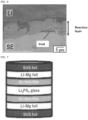
- a 10.0 mm ⁇ SUS foil having a film thickness of 20 pm was further attached to both sides thereof. This was vacuum-sealed in an aluminum laminate film having a thickness of 150 pm (50 pm of which was an aluminum evaporated film). Thereafter, cold isostatic pressing (CIP) was performed at 80 MPa for 2 minutes to prepare a symmetric cell 1.
- CIP cold isostatic pressing
- a symmetric cell with a Sn thin film was prepared.
- the LPS pellet used for the symmetric cell was the same as that prepared in step II above.
- a Sn thin film was formed using Sn on both sides of the LPS pellet prepared in the above step II. Sputtering was performed using Ar as the sputtering gas for 6 minutes at a sputtering power of about 6.5 W to provide a Sn thin film having a thickness of 200 nm.
- a symmetric cell 2 was prepared in the same manner as in step IV, except that a Li foil having a film thickness of 250 ⁇ m was attached instead of the Li 0.93 Mg 0.07 foil to both sides of the LPS pellet on which the thin film prepared in the above step V had been formed.
- a schematic diagram of the prepared symmetric cell 2 is shown in FIG. 1B .
- a symmetric cell 3 was prepared in the same manner as in step IV, except that a Li foil having a film thickness of 250 pm was attached instead of the Li 0.93 Mg 0.07 foil to both sides of the LPS pellet prepared in the above step II.
- a schematic diagram of the prepared symmetric cell 3 is shown in FIG. 1C .
- a constant current cycle test was performed using the symmetric cells 1 to 3 prepared in Examples 1 and 2 and Comparative Example 1.
- the test temperature was 100 °C
- the cell confining pressure was 1 MPa
- the energization was conducted with one hour each of charging and discharging defined as one cycle and with the current increased from 0.2 mA by 0.2 mA every five cycles.
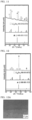
- FIGS. 2 and 3 show the results of the constant current cycle tests performed on the symmetric cells 1 to 3 .
- FIG. 2 shows the results of symmetric cells 1 and 3
- FIG. 3 shows the result of symmetric cells 2 and 3.
- FIGS. 2 and 3 show that symmetric cells 1 and 2 did not short-circuit even at a current higher than the current density (indicated by the arrows in FIGS. 2 and 3 ) at which symmetric cell 3 short-circuited, and that symmetric cells 1 and 2 using the negative electrode composite of the present invention have improved dissolution and precipitation characteristics.
- the interface between the solid electrolyte and the negative electrode after the short circuit was observed by the SEM.
- the symmetric cell was cut out perpendicularly to the lamination plane, and the cutout section was observed.
- FIG. 4 is a cross-sectional view of symmetric cell 1 after a short circuit
- FIG. 5 is a cross-sectional view of symmetric cell 2 after a short circuit
- FIG. 6 shows symmetric cell 3 after a short circuit.
- FIGS. 4 and 6 show that a reaction layer was formed at the interface of Li/Li 3 PS 4 by the reductive decomposition of Li 3 PS 4 .
- FIG. 5 shows no reaction layer, indicating that the generation of the reaction layer was suppressed by the Sn thin film. It is presumed that since Sn is not solid soluble in Li, it did not diffuse into Li of the negative electrode, and the form of the layer was maintained.
- a Sn thin film was formed using Sn on both sides of the LPS pellet prepared in the above step II. Sputtering was performed for 6 minutes in the same manner as described above to provide a Sn thin film having a thickness of 200 nm.
- a 10.0 mm ⁇ Li 0.93 Mg 0.07 foil prepared in the same manner as in the above step III was attached thereto.
- a 10.0 mm ⁇ SUS foil having a film thickness of 20 pm was further attached to both sides thereof. This was vacuum-sealed in an aluminum laminate film. Thereafter, cold isostatic pressing (CIP) was performed under the same conditions as described above to prepare a symmetric cell 4.
- CIP cold isostatic pressing
- FIG. 9 shows that there was no reaction layer in the symmetric cell 4, indicating that the generation of the reaction layer was suppressed by the Sn thin film even when the Li-Mg negative electrode active material was used.
- X-ray diffraction (XRD) measurement was performed to analyze the structure of the interface between the solid electrolyte and the negative electrode of each of symmetric cells 1, 2, and 4 short-circuited in the above constant current cycle tests.
- the attachment of the sample to the nonreflective sample plate and the sealing of the sample into the airtight sample holder were all performed in a glove box under an argon atmosphere.
- the measurement was performed after the SUS foil of the short-circuited symmetric cell was peeled off.
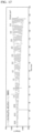
- FIGS. 10 to 12 The results of XRD measurements are shown in FIGS. 10 to 12 .
- FIG. 10 shows the measurement result of symmetric cell 1
- FIG. 11 shows the measurement result of symmetric cell 2
- FIG. 12 shows the measurement result of measured cell 4.
- the figures also include the results of a measurement of Li 22 Sn 5 , a measurement of Li, and a measurement of Li 2 S for comparison.
- FIG. 10 shows that a peak of Li 2 S, which is a reduction product of Li, was observed at the interface of symmetric cell 1.
- FIG. 11 shows that a peak of Li 22 Sn 5 , which is the most Li-rich alloy phase, was observed at the interface of symmetric cell 2.
- FIG. 12 shows that a peak of Li 22 Sn 5 was observed at the interface of symmetric cell 4, indicating that the generation of the reduction product Li 2 S was suppressed by the Sn thin film even when the Li-Mg negative electrode active material was used.
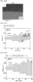
- the interface between the solid electrolyte and the negative electrode of each of symmetric cells 1, 2, and 4 short-circuited in the above constant current cycle tests was subjected to a SEM-EDS measurement.
- the measurement was performed at an acceleration voltage of 8 kV.
- FIGS. 13A and 13B The measurement result of symmetric cell 1 is shown in FIGS. 13A and 13B , the measurement result of symmetric cell 2 is shown in FIGS. 14A and 14B , and the measurement result of symmetric cell 3 is shown in FIGS. 15A and 15B.
- FIG. 13B shows that Mg did not exist in the reaction layer.
- FIGS. 14B and 15B show that Sn existed as a film even after the short circuit.
- a symmetric cell 5 was prepared in the same manner as in Example 2, except that sputtering was performed for 1 minute and the thickness of the Sn thin film was 60 nm.
- a symmetric cell 6 was prepared in the same manner as in Example 2, except that sputtering was performed for 3 minute and the thickness of the Sn thin film was 100 nm.
- FIG. 16 show the results of symmetric cells 5 and 6 together with the results of symmetric cell 2.
- FIG. 16 shows that the dissolution and precipitation characteristics are improved by increasing the thickness of the film.
- a symmetric cell was prepared using, as the solid electrolyte, a pellet prepared using 54Li 3 PS 4 -46LiI instead of the LPS pellet prepared in the above step II.
- a 54Li 3 PS 4 •46LiI pellet was prepared in the same manner as in the above step II, except that the 54Li 3 PS 4 •46LiI powder prepared in the above step VI was used instead of the LPS powder.
- a symmetric cell 7 was prepared in the same manner as in Example 3, except that the 54Li 3 PS 4 •46LiI pellet prepared in the above step VII was used.
- FIG. 17 shows that even when 54Li 3 PS 4 •46LiI is used as the solid electrolyte instead of LPS, the symmetric cell having the Li-Mg negative electrode active material and the Sn thin film has excellent dissolution and precipitation characteristics.
- FIG. 18 shows the results of an XRD measurement performed on the symmetric cell 7 after a constant current cycle test.
- the figure also includes the result of a measurement of Li 22 Sn 5 and the result of a measurement of Li for comparison.
- a peak of Li 22 Sn 5 was observed at the interface of symmetric cell 7, indicating that the generation of the reduction product Li 2 S was suppressed by the Sn thin film as in symmetric cell 4.
- FIGS. 20A and 20B show the measurement results by the SEM-EDS, respectively.
- FIG. 20A shows the results for Sn
- FIG. 20B shows the results for I.
- FIG. 19 shows that no reaction layer was formed in symmetric cell 7 as in symmetric cell 4.
- FIGS. 20A and 20B show that Sn existed as a film even after the short circuit.
- a constant current cycle test was performed at room temperature to measure the performance.
- the test temperature was 25°C
- the cell confining pressure was 1 MPa
- the energization was conducted with one hour each of charging and discharging used as one cycle and with the current increased from 0.05 mA by 0.05 mA every five cycles.
- FIGS. 21A and 21B show the results of the constant current cycle tests.
- FIG. 21A shows the results of symmetric cell 3
- FIG. 21B shows the measurement results of symmetric cell 4.
- FIGS. 21A and 21B show that symmetric cell 4, which has the Li-Mg negative electrode active material and the Sn thin film, has superior dissolution and precipitation characteristics than symmetric cell 3 even at room temperature.
- FIG. 22 shows the results of XRD measurements performed on symmetric cells 4 and 3 after the constant current cycle tests.
- the top graph shows the results of symmetric cell 3, and the second graph from the top shows the results of symmetric cell 4.
- the figure also includes the result of a measurement of Li 22 Sn 5 and the result of a measurement of Li for comparison.
- FIG. 22 shows that a peak of Li 22 Sn 5 was observed at the interface of symmetric cell 4.
- FIG. 23 shows that the generation of a reaction layer was suppressed by the insertion of the Sn thin film. This indicates that the interface was protected by the Sn thin film even in operation at room temperature.
Landscapes
- Chemical & Material Sciences (AREA)
- Chemical Kinetics & Catalysis (AREA)
- Electrochemistry (AREA)
- General Chemical & Material Sciences (AREA)
- Engineering & Computer Science (AREA)
- Materials Engineering (AREA)
- Manufacturing & Machinery (AREA)
- Metallurgy (AREA)
- Mechanical Engineering (AREA)
- Organic Chemistry (AREA)
- Physics & Mathematics (AREA)
- Condensed Matter Physics & Semiconductors (AREA)
- General Physics & Mathematics (AREA)
- Inorganic Chemistry (AREA)
- Secondary Cells (AREA)
- Battery Electrode And Active Subsutance (AREA)
Applications Claiming Priority (2)
| Application Number | Priority Date | Filing Date | Title |
|---|---|---|---|
| JP2020131708 | 2020-08-03 | ||
| PCT/JP2021/027951 WO2022030333A1 (ja) | 2020-08-03 | 2021-07-28 | 負極複合体及び二次電池 |
Publications (2)
| Publication Number | Publication Date |
|---|---|
| EP4190928A1 true EP4190928A1 (de) | 2023-06-07 |
| EP4190928A4 EP4190928A4 (de) | 2025-05-21 |
Family
ID=80117455
Family Applications (1)
| Application Number | Title | Priority Date | Filing Date |
|---|---|---|---|
| EP21851947.8A Pending EP4190928A4 (de) | 2020-08-03 | 2021-07-28 | Negativelektrodenverbundkörper und sekundärbatterie |
Country Status (5)
| Country | Link |
|---|---|
| US (1) | US20230290937A1 (de) |
| EP (1) | EP4190928A4 (de) |
| JP (1) | JP7794449B2 (de) |
| CN (1) | CN116057191A (de) |
| WO (1) | WO2022030333A1 (de) |
Families Citing this family (3)
| Publication number | Priority date | Publication date | Assignee | Title |
|---|---|---|---|---|
| JP2024011645A (ja) * | 2022-07-15 | 2024-01-25 | 株式会社Gsユアサ | 全固体二次電池用セパレータ及び全固体二次電池 |
| JP7845235B2 (ja) * | 2022-10-20 | 2026-04-14 | トヨタ自動車株式会社 | 二次電池及びその製造方法 |
| JP7772016B2 (ja) * | 2023-03-29 | 2025-11-18 | トヨタ自動車株式会社 | 全固体電池および全固体電池の製造方法 |
Family Cites Families (23)
| Publication number | Priority date | Publication date | Assignee | Title |
|---|---|---|---|---|
| CA1222543A (fr) * | 1984-04-11 | 1987-06-02 | Hydro-Quebec | Anodes denses d'alliages de lithium pour batteries tout solide |
| JPH0760687B2 (ja) * | 1987-05-26 | 1995-06-28 | ソニー株式会社 | 有機電解質電池 |
| JP3148293B2 (ja) * | 1991-08-20 | 2001-03-19 | 三洋電機株式会社 | 非水電解液二次電池 |
| JP2968447B2 (ja) * | 1994-02-22 | 1999-10-25 | 三菱電線工業株式会社 | リチウム二次電池用負極合金およびリチウム二次電池 |
| JP2936217B2 (ja) * | 1994-09-08 | 1999-08-23 | 工業技術院長 | リチウム電池とその負極担体の製造方法 |
| JPH08130007A (ja) * | 1994-10-27 | 1996-05-21 | Mitsubishi Cable Ind Ltd | 負極及びLi二次電池 |
| EP1143547A4 (de) * | 1999-09-24 | 2006-04-26 | Matsushita Electric Industrial Co Ltd | Lithiumzelle |
| JP3953711B2 (ja) | 2000-06-16 | 2007-08-08 | 三星エスディアイ株式会社 | リチウム二次電池用の負極材料及びリチウム二次電池用の電極及びリチウム二次電池及びリチウム二次電池用の負極材料の製造方法 |
| JP4152086B2 (ja) | 2001-03-23 | 2008-09-17 | 三洋電機株式会社 | リチウム二次電池用電極及びリチウム二次電池 |
| JP3755502B2 (ja) | 2002-09-11 | 2006-03-15 | ソニー株式会社 | 非水電解質電池 |
| JP3877170B2 (ja) | 2003-03-28 | 2007-02-07 | 日立マクセル株式会社 | 非水二次電池用負極、その製造方法および前記負極を用いた非水二次電池 |
| US7514180B2 (en) * | 2004-03-16 | 2009-04-07 | Toyota Motor Engineering & Manufacturing North America, Inc. | Battery with molten salt electrolyte and protected lithium-based negative electrode material |
| KR100800395B1 (ko) * | 2006-09-07 | 2008-02-04 | 한양대학교 산학협력단 | 리튬 이차 전지용 음극, 이의 제조방법 및 이를 포함하는리튬 이차 박막 전지 |
| JP6423361B2 (ja) * | 2012-12-19 | 2018-11-14 | イムラ アメリカ インコーポレイテッド | エネルギー貯蔵用の負極活物質 |
| JP2015032447A (ja) | 2013-08-02 | 2015-02-16 | 尾池工業株式会社 | 負極材料、及びリチウム二次電池 |
| WO2017094237A1 (ja) * | 2015-11-30 | 2017-06-08 | パナソニックIpマネジメント株式会社 | 非水電解質二次電池 |
| JP6290520B1 (ja) * | 2016-07-26 | 2018-03-07 | 株式会社三徳 | マグネシウム−リチウム合金及びマグネシウム空気電池 |
| CN109216655B (zh) * | 2017-07-07 | 2020-11-13 | 北京好风光储能技术有限公司 | 一种充放电相互独立的锂浆料电池系统 |
| US20210104774A1 (en) * | 2018-02-01 | 2021-04-08 | Honda Motor Co., Ltd. | Solid-state battery and method for producing solid-state battery |
| JP7063653B2 (ja) | 2018-02-20 | 2022-05-09 | 三星電子株式会社 | 全固体型二次電池 |
| JP7154847B2 (ja) * | 2018-07-06 | 2022-10-18 | Fdk株式会社 | 全固体電池の製造方法 |
| JP7327005B2 (ja) | 2019-04-26 | 2023-08-16 | トヨタ自動車株式会社 | 全固体電池及びその製造方法 |
| HUE064174T2 (hu) * | 2019-10-22 | 2024-02-28 | Samsung Electronics Co Ltd | Szilárdtest-akkumulátor és eljárás szilárdtest-akkumulátor gyártására |
-
2021
- 2021-07-28 CN CN202180058821.9A patent/CN116057191A/zh active Pending
- 2021-07-28 WO PCT/JP2021/027951 patent/WO2022030333A1/ja not_active Ceased
- 2021-07-28 US US18/040,340 patent/US20230290937A1/en active Pending
- 2021-07-28 EP EP21851947.8A patent/EP4190928A4/de active Pending
- 2021-07-28 JP JP2022541472A patent/JP7794449B2/ja active Active
Also Published As
| Publication number | Publication date |
|---|---|
| WO2022030333A1 (ja) | 2022-02-10 |
| EP4190928A4 (de) | 2025-05-21 |
| CN116057191A (zh) | 2023-05-02 |
| US20230290937A1 (en) | 2023-09-14 |
| JPWO2022030333A1 (de) | 2022-02-10 |
| JP7794449B2 (ja) | 2026-01-06 |
Similar Documents
| Publication | Publication Date | Title |
|---|---|---|
| EP1738425B1 (de) | Verfahren zur herstellung eines aktiven anodenmaterials mit verbesserten elektrochemischen eigenschaften | |
| JP7335022B2 (ja) | リチウム2次電池 | |
| JP2024539121A (ja) | 負極シート、二次電池、電池モジュール、電池パック及び電力消費装置 | |
| EP1936731B1 (de) | Wiederaufladbare Lithiumbatterie | |
| US8334073B2 (en) | Non-aqueous electrolyte secondary battery and method of manufacturing negative electrode thereof | |
| JP5060010B2 (ja) | 非水電解質二次電池 | |
| WO2005076391A1 (en) | Electrode additives coated with electro conductive material and lithium secondary comprising the same | |
| JP2023529142A (ja) | 負極活物質としてシリコン(Si)を含む全固体電池 | |
| US8148014B2 (en) | Composite anode active material, method of preparing the same, and anode and lithium battery containing the material | |
| US20170244104A1 (en) | Cathode active material and battery | |
| JP2014225324A (ja) | 非水電解質二次電池 | |
| EP4190928A1 (de) | Negativelektrodenverbundkörper und sekundärbatterie | |
| US8236447B2 (en) | Electrode active material for non-aqueous secondary batteries | |
| US12206091B2 (en) | Lithium molybdate anode material | |
| JP5119584B2 (ja) | 非水電解質二次電池およびその負極の製造法 | |
| US12180563B2 (en) | Manufacturing method of porous silicon material, porous silicon material, and power storage device | |
| US20240162430A1 (en) | Ion conductor and utilization thereof | |
| EP4116261A1 (de) | Feste lösung, aktives elektrodenmaterial, elektrode und sekundärbatterie | |
| JPH09171829A (ja) | リチウム二次電池用正極活物質およびリチウム二次電池 | |
| JP2024131982A (ja) | 蓄電デバイス用電極、蓄電デバイス及び蓄電デバイス用電極の製造方法 |
Legal Events
| Date | Code | Title | Description |
|---|---|---|---|
| STAA | Information on the status of an ep patent application or granted ep patent |
Free format text: STATUS: THE INTERNATIONAL PUBLICATION HAS BEEN MADE |
|
| PUAI | Public reference made under article 153(3) epc to a published international application that has entered the european phase |
Free format text: ORIGINAL CODE: 0009012 |
|
| STAA | Information on the status of an ep patent application or granted ep patent |
Free format text: STATUS: REQUEST FOR EXAMINATION WAS MADE |
|
| 17P | Request for examination filed |
Effective date: 20230227 |
|
| AK | Designated contracting states |
Kind code of ref document: A1 Designated state(s): AL AT BE BG CH CY CZ DE DK EE ES FI FR GB GR HR HU IE IS IT LI LT LU LV MC MK MT NL NO PL PT RO RS SE SI SK SM TR |
|
| DAV | Request for validation of the european patent (deleted) | ||
| DAX | Request for extension of the european patent (deleted) | ||
| A4 | Supplementary search report drawn up and despatched |
Effective date: 20250424 |