EP4186779A2 - Dispositif de réglage pour une bicyclette et procédé de commande ou de réglage de tels dispositifs de réglage - Google Patents
Dispositif de réglage pour une bicyclette et procédé de commande ou de réglage de tels dispositifs de réglage Download PDFInfo
- Publication number
- EP4186779A2 EP4186779A2 EP23020013.1A EP23020013A EP4186779A2 EP 4186779 A2 EP4186779 A2 EP 4186779A2 EP 23020013 A EP23020013 A EP 23020013A EP 4186779 A2 EP4186779 A2 EP 4186779A2
- Authority
- EP
- European Patent Office
- Prior art keywords
- switching
- shift
- drive
- gear
- trimming
- Prior art date
- Legal status (The legal status is an assumption and is not a legal conclusion. Google has not performed a legal analysis and makes no representation as to the accuracy of the status listed.)
- Pending
Links
Images








Classifications
-
- B—PERFORMING OPERATIONS; TRANSPORTING
- B62—LAND VEHICLES FOR TRAVELLING OTHERWISE THAN ON RAILS
- B62M—RIDER PROPULSION OF WHEELED VEHICLES OR SLEDGES; POWERED PROPULSION OF SLEDGES OR SINGLE-TRACK CYCLES; TRANSMISSIONS SPECIALLY ADAPTED FOR SUCH VEHICLES
- B62M9/00—Transmissions characterised by use of an endless chain, belt, or the like
- B62M9/04—Transmissions characterised by use of an endless chain, belt, or the like of changeable ratio
- B62M9/06—Transmissions characterised by use of an endless chain, belt, or the like of changeable ratio using a single chain, belt, or the like
- B62M9/10—Transmissions characterised by use of an endless chain, belt, or the like of changeable ratio using a single chain, belt, or the like involving different-sized wheels, e.g. rear sprocket chain wheels selectively engaged by the chain, belt, or the like
- B62M9/12—Transmissions characterised by use of an endless chain, belt, or the like of changeable ratio using a single chain, belt, or the like involving different-sized wheels, e.g. rear sprocket chain wheels selectively engaged by the chain, belt, or the like the chain, belt, or the like being laterally shiftable, e.g. using a rear derailleur
- B62M9/121—Rear derailleurs
- B62M9/122—Rear derailleurs electrically or fluid actuated; Controls thereof
-
- B—PERFORMING OPERATIONS; TRANSPORTING
- B62—LAND VEHICLES FOR TRAVELLING OTHERWISE THAN ON RAILS
- B62M—RIDER PROPULSION OF WHEELED VEHICLES OR SLEDGES; POWERED PROPULSION OF SLEDGES OR SINGLE-TRACK CYCLES; TRANSMISSIONS SPECIALLY ADAPTED FOR SUCH VEHICLES
- B62M25/00—Actuators for gearing speed-change mechanisms specially adapted for cycles
- B62M25/08—Actuators for gearing speed-change mechanisms specially adapted for cycles with electrical or fluid transmitting systems
-
- B—PERFORMING OPERATIONS; TRANSPORTING
- B62—LAND VEHICLES FOR TRAVELLING OTHERWISE THAN ON RAILS
- B62M—RIDER PROPULSION OF WHEELED VEHICLES OR SLEDGES; POWERED PROPULSION OF SLEDGES OR SINGLE-TRACK CYCLES; TRANSMISSIONS SPECIALLY ADAPTED FOR SUCH VEHICLES
- B62M9/00—Transmissions characterised by use of an endless chain, belt, or the like
- B62M9/04—Transmissions characterised by use of an endless chain, belt, or the like of changeable ratio
- B62M9/06—Transmissions characterised by use of an endless chain, belt, or the like of changeable ratio using a single chain, belt, or the like
- B62M9/10—Transmissions characterised by use of an endless chain, belt, or the like of changeable ratio using a single chain, belt, or the like involving different-sized wheels, e.g. rear sprocket chain wheels selectively engaged by the chain, belt, or the like
- B62M9/12—Transmissions characterised by use of an endless chain, belt, or the like of changeable ratio using a single chain, belt, or the like involving different-sized wheels, e.g. rear sprocket chain wheels selectively engaged by the chain, belt, or the like the chain, belt, or the like being laterally shiftable, e.g. using a rear derailleur
- B62M9/121—Rear derailleurs
- B62M9/123—Rear derailleurs changing gears automatically
Definitions
- the present invention relates to adjusting devices for bicycles, methods for controlling adjusting devices for bicycles and methods for adjusting such adjusting devices.
- An electromechanical actuating device for a bicycle in the form of an electric derailleur is, for example, from U.S. 2015/0111675 A1 known and comprises an element to be fastened to the bicycle frame, a movable element for this purpose and an electromechanical drive which moves the movable element in relation to the fixed element in order to set a desired switching stage.
- the electromechanical drive is operated by a motor gear arrangement which gears down the rotation of an electric motor and provides it at a transmission output shaft for moving the movable element.
- a position detection device is provided which, in the form of an electromagnetic rotation sensor, determines the rotational position of a position detection wheel meshing with the transmission output shaft.
- the position detection wheel is additionally engaged with a tension wheel which is continuously biased in one direction of rotation by a torsion spring. Regardless of the direction of rotation of the transmission output shaft, the position detection wheel is always in contact with the same tooth flanks.
- the disadvantage of this design is that the force of the torsion spring depends on the rotary position of the tensioning wheel and the tensioning force designed for optimal operation only acts at a specific angle of rotation or over a small range of angles of rotation. On the other hand, at the beginning and at the end of the rotation angle range, the clamping force of the torsion spring is either too low, so that the backlash reduction is no longer reliably guaranteed, or is too high, so that the torsion spring influences the output torque of the transmission too much.
- Another electromechanical actuator is from DE 42 12 320 A1 known.
- This adjusting device also comprises a stationary element to be fastened to the bicycle frame, an element that can be moved in relation to the stationary element, and an electromechanical drive that provides the driving force for a movement of the movable element.
- the adjusting device is part of an electromechanical rear derailleur for setting different switching stages of a derailleur.
- the known actuating device is set up to recognize such a blockage and to interrupt the motor current.
- an overload clutch can also be used, which interrupts the power flow from the motor to the movable element if a predetermined overload torque is exceeded at the overload clutch.
- the maximum motor current, the overload torque and the time at which the motor current is switched off must be coordinated very precisely in order to achieve the desired effect of avoiding damage. If the overload torque is set too high, the motor and gearbox will be subjected to a very high load if the moving element is blocked. If the overload torque is set too low, the overload clutch frequently trips incorrectly and thus both a functional impairment of the actuating device and a excessive noise. In addition, measuring the motor current to detect a blocked state is relatively complex.
- the ones from the DE 42 12 320 A1 well-known electromechanical actuating device also has a trimming function for setting and readjusting the alignment between the rear derailleur and sprocket set. Precise positioning between the rear derailleur and the sprocket set is of crucial importance for a grinding-free setting of the respective switching stages, especially in rear derailleurs with a large number of gears.
- the trimming function of the known control device allows the switching positions to be shifted by a specific trimming amount in order to compensate for manufacturing tolerances of the rear derailleur or deviations between different frame models and different sprocket sets.
- the well-known adjusting device thus realizes the same trimming function as is already known from purely mechanical rear derailleur by adjusting the length of the shift cable.
- a further difficulty in setting the shift positions by the conventional trim function arises when the number of shift steps increases corresponding to an increase in the number of sprockets in the sprocket pack, for example an increase in the number of sprockets from conventionally around five to seven to ten or more, for example twelve Pinion.
- a corresponding axial enlargement of the sprocket set and thus the distance between the lowest shifting position and the highest shifting position leads to a particularly strong skew of the chain between the front chain wheel and the sprocket set in the lowest or highest shifting positions.
- the skew of the chain exerts a force in the axial direction on the chain guide wheels of the derailleur and thus stresses the derailleur in a direction that counteracts precise adjustment of the shift positions.
- the rear derailleur does not reach the desired target positions in the highest or lowest gears and the result is improper chain movement, improper shifting, running noises in these gears and possibly even unintentional shifting.
- a first object is to provide an adjusting device for a bicycle, which includes an electromechanical drive with a motor and a gear, wherein a particularly precise and reliable operation is made possible by an increased positional accuracy between the elements of the drive.
- an adjusting device for a bicycle comprising a fixed element which is arranged stationary in relation to a bicycle frame, a movable element which is movable in relation to the fixed element, an electromechanical drive , which provides driving force for a movement of the movable element, wherein the electromechanical drive comprises a motor and a transmission driven by the motor, the transmission comprising a first gear wheel and a second gear wheel meshing with the first gear wheel, the second gear wheel having two Partial gears each having the same number of teeth, both of which are simultaneously engaged with the first gear wheel, the partial gears being rotatable about the same axis of rotation and being biased relative to one another by a force in the direction of rotation about the axis of rotation.
- gear wheels are preferably understood to mean gear wheels.
- individual gear wheels could also fulfill the functions described herein without tooth engagement, for example by frictional engagement, so that such non-toothed wheels are also regarded as gear wheels.
- the second gear wheel has two sub-wheels with the same number of teeth, which are biased towards one another and are simultaneously in mesh with the first gear wheel.
- the teeth of the two partial wheels that are currently engaged with the first gear wheel are pressed by the force in the direction of opposite tooth flanks of the first gear wheel and rest there without play. Irrespective of the direction of rotation of the first gear wheel, the teeth of the two sub-wheels are therefore always preloaded without play in engagement with the respective tooth flanks of the first gear wheel.
- an accuracy of the rotational position of the second gear can be increased regardless of the rotational position of the first gear.
- the force between the two part-wheels can be generated by a force-generating device which is functionally arranged between the two part-wheels, so that it is supported on the one hand on a first part-wheel of the two part-wheels and on the other hand on a second part-wheel of the two part-wheels.
- the force-generating device can in particular be an elastic device, for example a torsion spring.
- an elastic device is not supported on a fixed component, but generates a relative force between the two partial wheels to prestress the partial wheels in opposite directions of rotation.
- the force that prestresses the part wheels against one another is independent of a rotational position of the second gear wheel.
- a reliable backlash reduction can be achieved in every rotational position of the second gear wheel, and the force can be dimensioned in such a way that it does not significantly affect the torque on the first gear wheel.
- a first partial wheel of the two partial wheels can be mounted with a predetermined first radial play relative to the axis of rotation and a second partial wheel of the two partial wheels can be mounted with a predetermined second radial play relative to the axis of rotation, which is smaller than the first radial play , or be stored without radial play.
- the first partial wheel, which is mounted with (larger) play, is then able to position itself slightly eccentrically to the axis of rotation in order to bring itself into a different position relative to the second partial wheel not only in the direction of rotation but also in the radial direction and to create a backlash in relation to the to further eliminate the first gear wheel.
- the radial (larger) play of the first part wheel is also controlled by a force, for example by a Power of the same power generating device, which also biases the relative rotation of the two partial wheels to each other.
- the (greater) radial play of the first partial gear can be realized in particular by the fact that both partial gears are mounted on a common gear shaft, with a diameter of an axial section of the gear shaft supporting the first partial gear being smaller than a diameter of an axial section of the gear shaft supporting the second partial gear gear shaft.
- both partial wheels can be structurally identical, so that costs and assembly work are reduced.
- a diameter of a central opening in the first partial wheel that accommodates the transmission shaft could be larger than a diameter of a central opening in the second partial wheel that accommodates the transmission shaft.
- the adjusting device comprises a position detection device for detecting a current rotational position of the first gear wheel of the transmission, the second gear wheel being part of this position detection device.
- the second gear wheel can carry a sensor element of a rotational position sensor, or the position detection device can comprise a fifth gear wheel, which meshes with the second gear wheel, in particular with both sub-wheels of the second gear wheel, and which carries a sensor element of a rotational position sensor.
- an electromechanical actuating device for a bicycle comprising a stationary element which is arranged in a stationary manner with respect to a bicycle frame, a movable element which is movable with respect to the stationary element, an electromechanical drive which provides driving force for movement of the movable element, the electromechanical drive having a motor and a motor-driven transmission and wherein the transmission has at least one stepped gear wheel with at least two coaxial gear wheels with different numbers of teeth, the two gear wheels of the stepped gear wheel each having a central opening into which a gear shaft is inserted.
- both gear wheels of the step gear wheel are thus formed separately from the transmission shaft.
- the two gears can in turn also be designed as separate components, in particular components that are fastened to one another, or integrally with one another.
- the separate design of the gears and the gear shaft allows for the respective elements of the stepped gear a design and quality adapted to their intended use.
- the material of the gear shaft can have a lower hardness in order to prevent hardening distortion, especially with longer gear shafts, while the material of the gears can have a greater hardness in order to be able to transmit greater torques reliably and with less wear.
- at least one of the two gears is rotatably held on the transmission shaft, preferably both gears are rotatable. The rotational forces of the transmission are thus not introduced into the transmission shaft, so that the transmission shaft can be mounted in a non-rotatable manner at low cost.
- an adjusting device for a bicycle comprising a fixed element which is arranged stationary with respect to a bicycle frame, a movable element which is arranged with respect to the fixed element is movable, an electromechanical drive which provides driving force for a movement of the movable element, wherein the electromechanical drive comprises a housing and a motor fastened in the housing, the actuating device also having a motor mount which has first fastening means for fastening the motor mount to the housing and second fastening means, separate from the first fastening means, for fastening the engine to the engine mount.
- the first fastening means can be specially adapted to the material of the housing, for example to ensure precise and stable positioning even with a housing made of softer material, while the second fastening means can be set up for simple and secure assembly of the motor.
- the first fastening means can be realized in that the motor mount is at least partially embedded, in particular molded, into the material of the housing.
- the motor mount can have special projections and/or recesses, for example, which ensure a particularly secure form-fitting hold in the material of the housing.
- a screw connection or an adhesive connection can be used as the first fastening means.
- the housing is formed of a plastic material to reduce weight.
- the engine mount can then, for example Be formed metal to allow easy and accurate assembly of the motor on the motor mount, for example by a screw connection.
- a second object of the present invention is to provide an adjusting device for a bicycle and a method for controlling or adjusting an adjusting device for a bicycle, which in the event of a malfunction, in particular due to external mechanical influences, ensure an appropriate reaction of the adjusting device and prevent damage or avoid excessive stress on the actuator.
- the above second object is achieved by a method for controlling an adjusting device for a bicycle, the adjusting device comprising: a fixed element which is arranged in a stationary manner with respect to a bicycle frame, a movable element which is is movable on the fixed element, an electromechanical drive which provides driving force for a movement of the movable element on the basis of a drive control signal, and a fault detection device which detects a fault relating to the movement of the movable element, the method having the following steps: generating a first drive control signal to drive the electromechanical drive at a first drive power when the fault detection device does not detect a fault, and generating a second drive control signal to drive the electromechanical drive at a second drive power when the fault detection device detects a fault, the second drive power being less than the first drive power, but is greater than zero.
- the engine runs with a reduced driving power operated.
- this makes it possible to avoid overloading the engine or the transmission by reducing the drive power.
- the second drive power is greater than zero, so that the actuating device continues to attempt to carry out the desired actuating process. So if there is only a temporary impairment of the freedom of movement of the movable element, the desired movement can still be carried out without the driver having to issue a new operating command.
- actuating devices are generally designed in such a way that the drive power applied to the electromechanical drive is significantly greater than the power currently required for moving the movable element. In this way, it is ensured that a faster and more reliable actuating process is also guaranteed when the frictional forces within the actuating device are increased due to wear or dirt.
- the invention of the fourth aspect makes use of this leeway in order to maintain a reduced second drive power for a while after a disturbance has been detected and to continue trying to carry out the desired actuating movement after all. During this time, however, the actuating device is not overly stressed. Only if the fault persists for a longer period of time can the drive power be switched off completely and an error message issued.
- a fault can be detected on the basis of a signal from a position detection device.
- a transmission of the electromechanical drive can have a rotational position sensor, which detects a rotational position of one of the gear wheels of the transmission.
- a fault can be detected when the position detection device determines that the electromagnetic drive or the movable element is not moving despite the presence of drive power.
- the second drive control signal is then preferably generated after a first period of time has elapsed after the fault has been detected, in order to reduce the drive power to the second drive power.
- the electromechanical drive is stopped if the disturbance lasts a predetermined second time after the second drive signal was generated.
- the actuating device may further comprise an overload clutch which is operatively arranged between a drive source of the electromechanical drive and an output member of the electromechanical drive and which interrupts a transmission of drive force from the drive source to the output member when an the force acting on the overload clutch exceeds a predetermined overload threshold value.
- an overload clutch can interrupt the power path between the movable element and the drive source in the event of an extraordinary load, for example due to an impact or jamming of the actuating device, in order to avoid damage to the drive source or other elements of the electromechanical drive.
- a slipping clutch with a defined and optionally adjustable overload threshold value can be used.
- the first drive power is dimensioned in such a way that if the movement of the output member is blocked, the force acting on the overload clutch is greater than the overload threshold value, so that the drive with the first drive power would trigger the overload clutch.
- the second drive power is dimensioned such that in the event of the movement of the output member being blocked, the force acting on the overload clutch is less than the overload threshold value, so that the second drive power is not sufficient to trigger the overload clutch.
- a third object of the invention is to provide an adjusting device for a bicycle, in particular for a bicycle gear system, which allows the adjusting device to be set and matched more precisely to the specific installation situation and/or allows signs of wear to be compensated for and in this way more precise operation ensures.
- an adjusting device for a bicycle comprising a stationary element which is arranged in a stationary manner with respect to a bicycle frame, a movable element which is movable with respect to the stationary element, an actuating device, which allows the selection of a desired shift stage from a plurality of available shift stages and which is set up to move the movable element into a shift position corresponding to the selected shift stage, and a trimming device which allows the shift positions associated with the shift stages to be adjusted, the trimming device therefor is set up to adjust the associated switching positions by different trimming amounts for at least two switching stages.
- the trimming device is thus able to adjust (trim) different shift positions with different trimming amounts, whereby the possibilities for adaptation and readjustment of the actuating device are multiplied.
- the trimming device can in particular have an adjustment means in order to adjust the trim amounts relative to one another for at least two switching stages, preferably for all switching stages.
- the trim amounts of a plurality of switching stages, preferably all switching stages can be adjusted simultaneously relative to one another by a single adjustment process.
- the trimming device can be set up to adjust the respective switching positions with increasing trimming amounts for all switching stages of a series of successive switching stages, or to adjust the respective switching positions with decreasing trimming amounts for all switching stages for a series of sequential switching stages. In this way, in particular, frequent misalignments between the shift positions and the respective sprockets can be corrected, which occur to a greater extent in the extreme shift stages (lowest or highest shift stages).
- a neutral (e.g. middle) shift stage corresponding to a neutral (e.g. middle) shift position in which no or only a slight chain skewing occurs is assigned a predetermined first trim amount and if shift stages, whose shift positions have incrementally larger distances from the shift position of the neutral shift stage, incrementally larger trim amounts are assigned.
- trim amounts for the individual switching stages can be stored in a memory, in particular in the form of different trimming programs as respective data sets with trim values for each switching stage, or can be entered as input values by a user or another device in the actuating device become.
- mechanical adjusting means such as adjusting screws, can be used in order to carry out the desired adjustment of the switching positions.
- the actuating device can have a shift control cable and a take-up body for selectively winding or releasing the shift control cable, wherein the take-up body can then have a trimming element, by means of which a winding contour of the take-up body can be adjusted. By influencing the winding contour, it can then be achieved that an adjustment of the cable pull during a trimming process affects different switching positions to a different extent.
- an actuator for a bicycle comprising: a fixed member which is stationary with respect to a bicycle frame, a movable member which is movable with respect to the fixed member , an electromechanical drive, which provides driving force for a movement of the movable element, an electronic control device, in which for a plurality of shift stages, at least one shift position parameter is stored for each shift stage, which corresponds to a shift position of the movable element in the respective shift stage, wherein the control device is set up to, in response to a shift stage selection signal, which represents a shift stage to be set, the electromechanical drive on the basis of to control the switching position parameter of the switching stage to be set in such a way that the movable element reaches the switching position, the adjusting device also having a trimming device which is set up to change at least one of the switching position parameters independently of all the other switching position parameters at the instigation of a user.
- This adjusting device also allows more precise trimming or adjustment of the adjusting device in order to be able to react to a specific installation situation on the bicycle or to signs of wear, so that precise shifting can be ensured.
- switching position parameters for each switching stage are stored in an electronic control device, which parameters represent switching positions of the movable element in the respective switching stage.
- the switching position parameters can be set independently of one another, so that maximum freedom is created for the adjustment or trimming of the actuating device.
- a standard position parameter which corresponds to a predetermined standard switching position of the movable element, is preferably stored in the setting device for each switching stage of the plurality of switching stages.
- corrections therefore only have to be made if this is necessary for a specific switching position.
- the actuator can be quickly reset to a default state.
- the shift position parameter can, for example, be a deviation from the standard position parameter represent and are then also referred to as trim parameters, which allows intuitive operation.
- the actuating device comprises an acceleration sensor which provides information about a vibration of the actuating device.
- a vibration of the actuating device can contain information as to whether the movable element is in a shifting position that is optimal for the respective shift stage or how large the distance between the current shifting position and an optimal shifting position is.
- a misalignment between the movable element and the sprocket i.e. a deviation of the shifting position from an optimal shifting position, is noticeable through increased vibration or noise of the adjusting device, which result from vibrations of the chain, the adjusting device and the sprocket set.
- the actuating device can further comprise a program code executable on a portable device, the program code being set up to control the portable device to carry out the following steps: a) receiving a user input for selection a shift stage of the plurality of shift stages, and b) receiving a user input for setting and/or changing the shift position parameter.
- the trimming process can be carried out using a portable device, in particular a smartphone with a corresponding smartphone app.
- the user can set a valid shift step and then individually change the shift position parameter for this shift step (change the trim amount of the shift step) until an optimal shift position is reached.
- the above-mentioned third object of the invention is achieved by a method for adjusting an actuating device according to one of the preceding aspects, the method comprising the following steps: selecting a switching stage, retrieving a stored switching position parameter which corresponds to a switching position of a movable element of the Actuating device is assigned in the respective switching stage, from a memory, changing the switching position parameter, storing the changed switching position parameter in the memory.
- the actuating device can be individually adjusted or trimmed for each switching stage.
- the method can be carried out in particular using a portable device, in particular a smartphone with a corresponding app.
- the functional parameter of the setting device which represents the accuracy of the shift stage setting, can represent an oscillation or vibration of the setting device, for example, so that the shift position parameter is adjusted in the sense of reducing the vibration.
- the adjustment process or the trimming of the actuating device can be carried out essentially automatically, for example while driving, in order to offer the most realistic possible conditions for the adjustment process.
- a in figure 1 Bicycle generally designated 10, has a front wheel 12, a rear wheel 14 and a frame 16 in a manner known per se.
- the front wheel 12 is rotatably supported at lower ends of a front wheel fork 18 which is rotatably supported at its upper end on the frame 16 and carries handlebars 20 for steering the bicycle 10 .
- the rear wheel 14 is rotatably mounted on a rear end of the frame 16 about an axis of rotation A.
- the frame 16 also supports a saddle 22 and a crank assembly having pedal cranks 24 and a front chainring 26 attached thereto.
- a sprocket set 30 is mounted on the rear wheel 14 concentrically to the wheel axle and carries a plurality of sprockets of different diameters, i.e. with different numbers of teeth.
- a sprocket set with a total of eleven sprockets is provided, and the front chainring 26 is provided as a single wheel, so that a total of eleven shift stages can be set.
- other circuit configurations can be used, in particular multiple chainrings, between which it is possible to switch using a front derailleur.
- a rear derailleur with a rear derailleur 32 is used to set the switching stages of the rear sprocket set, which is also attached to a rear end of the frame 16 and forms part of one of the adjusting devices of the exemplary embodiment of the invention.
- a chain 34 encircles the sprocket pack 30 and the front sprocket 26 and runs through the rear derailleur 32 in order to transmit driving force from the front sprocket 26 to the sprocket pack 30 and thus to the rear wheel 14 .
- the Rear derailleur 32 is able to adjust the chain 34 in the axial direction with respect to the axis of rotation A of the rear wheel 14 in order to selectively align the chain 34 with one of the sprockets of the sprocket set 30 and accordingly lead it to the selected sprocket.
- a control element 36 is provided on the handlebar 20 so that a driver can set the rear derailleur to a desired gear stage.
- the operating element 36 transmits operating commands for controlling the switching mechanism 32 wirelessly by means of a radio link between a radio transmitter integrated in the operating element 36 and a radio receiver integrated in the switching mechanism 32 .
- a radio link between a radio transmitter integrated in the operating element 36 and a radio receiver integrated in the switching mechanism 32 .
- other variants are conceivable and can be used within the scope of the present invention in order to transmit operating commands from the driver from a control element to the rear derailleur 32, for example a wired transmission using an electrical signal line or a mechanical connection using a shift cable.
- the bicycle preferably includes a brake system, for example in the form of a front disc brake 38 and/or a rear disc brake 40 .
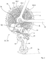
- FIG 2 shows an enlarged view of a rear section of the bicycle 10 in the area of the sprocket set 30 and the rear derailleur 32.
- the sprocket set 30 comprises a plurality of sprockets, eleven sprockets 30-1 ... 30-11 in the exemplary embodiment, which according to size are stacked coaxially on the rear wheel axle A and are non-rotatably connected to each other.
- the largest sprocket 30-1 can have 50 teeth, for example, while the smallest sprocket 30-11 can have nine to eleven teeth, for example.
- the sprockets 30-1...30-11 are arranged such that the largest sprocket 30-1 is further inside, ie closer to the center plane of the rear wheel, while the smallest sprocket 30-11 is further outside, ie further away from the center plane is arranged.
- directional information such as “inside”, “outside”, “above”, “below”, “front”, “back”, “sideways” and similar information refer to an upright, ready-to-ride position of the bicycle 10 on a horizontal surface.
- a direction from the largest sprocket 30-1 toward the smallest sprocket 30-11 is referred to as "outward,” while a direction from the smallest sprocket 30-11 toward the largest sprocket 30-1 is referred to as "inward.”
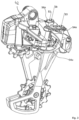
- the rear derailleur 32 comprises a fixed element 42, which is also referred to as a "B-knuckle” and which has a fastening section 43 for fastening to the frame 16, preferably using a derailleur hanger. Furthermore, the rear derailleur 32 includes a movable element 44, which is also referred to as a "P-knuckle” and carries a chain guide arrangement 46 with a lower chain guide wheel 48 and an upper chain guide wheel 50 in a manner known per se.
- the chain guide assembly 46 is rotatably supported on the movable member 44 about an axis B parallel to the axis A and is biased in the rearward direction, ie, in figure 2 clockwise, preloaded to keep the chain 34 taut and in particular to compensate for the different chain travels around the different sized sprockets 30-1...30-11.
- Movable member 44 is movably coupled to fixed member 42 by a hinge assembly 52 .
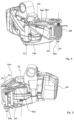
- the hinge assembly 52 is particularly in the Figures 3 to 5 easy to recognize and can be designed as in the exemplary embodiment of the parallelogram type.
- Such a joint arrangement 52 comprises at least one outer pivoting element, here an upper outer pivoting element 54o and a lower outer pivoting element 54u, and at least one inner pivoting element, here an upper inner pivoting element 56o and a lower inner pivoting element 56u.
- First ends of the upper and lower outer pivot members 54o, 54u are pivoted to the fixed member 42 at a first pivot axis S1.
- First ends of the upper and lower inner pivot members 56o, 56u are pivoted to the fixed member 42 at a second pivot axis S2 spaced from the first pivot axis. Second ends of the upper and lower outer pivot members 54o, 54u, opposite to the first ends, are pivoted to the movable member 44 at a third pivot axis S3. Second ends of the upper and lower inner pivot members 56o, 56u, opposite the first ends, are pivotally supported on the movable member 44 at a fourth pivot axis S4 spaced apart from the third pivot axis S3.
- pivot axes S1, S2, S3 and S4 essentially form the corner points of an articulated parallelogram and in this way allow a movement of the movable element 44 and thus the chain guide arrangement 46 in the axial direction (parallel to the main axis A) outwards and inwards, respectively to guide the chain 34 from one of the sprockets 30-1...30-11 to another sprocket.
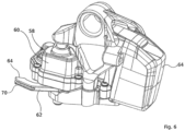
- the movable element 44 is moved by an electromechanical drive 58 (see also figure 6 ) having a motor-gearbox assembly housed in a housing 60 and providing power to move the moveable member at an output member movably coupled to the linkage assembly 52 or the moveable member 44.
- the output member is formed by a drive arm 62 which has a stop 64 which is mounted on a counter-stop 66 (see FIG figure 5 , drive arm 62 omitted here for illustration) of the lower inner pivot member 56u so as to be able to pivot the lower inner pivot member 56u in an outward direction, thereby causing the movable member 44 to move outwardly.
- the drive arm 62 is held in abutting contact with the lower inner pivoting member 56u under the tension of a spring 68, the spring 68 bearing on the one hand in a housing 70 on the drive arm 62 and on the other hand on the movable member 44.
- spring 68 may be supported on fourth pivot axis S4 and configured to bias movable member 44 in an inward direction.
- the electromechanical drive 58 is operated in such a way that the drive arm 62 moves in an outward direction, over the stop 64 and the counter stop 66 takes the lower inner pivoting element 56u directly with it.
- the electromechanical drive 58 is operated such that the drive arm 62 moves in an inward direction. The force of the spring 68 causes the joint arrangement 52 to follow this movement of the drive arm 62, i.e.
- the spring 68 keeps the counter-stop 66 of the lower inner pivoting element 56u in contact with the stop 64 of the drive arm 62.
- FIG 7 shows that the gear housing 60 of the electromechanical drive 58 is formed in the illustrated exemplary embodiment from an upper gear housing part 60o and a lower gear housing part 60u, which are fastened to one another by suitable connecting means, here screw connections 63, and in their interior a cavity for receiving the later define descriptive motor-transmission arrangement.
- the gear housing 60 can in turn be accommodated between two housing parts of the fixed element, for example between an upper housing part 42o on which also the attachment portion 43 is arranged to be attached to the frame 16, and a lower case 42u.
- the upper housing part 42o and the lower housing part 42u can be screwed together in order to fix the transmission housing 60 securely and without play in a precisely predetermined position.
- Power to operate the electromechanical drive 58 is provided by a removable battery 64 in the illustrated embodiment.
- the battery 64 and the transmission housing 60 can be coupled to one another or separated from one another both mechanically and electrically.
- Mechanical connection means can be formed, for example, by a hook 66 which engages in a matching recess 68 of the battery, or vice versa.
- Electrical connection means can be implemented by suitable pins 70 and matching recesses 72.
- the electromechanical actuator 58 may be powered by a remote power source connected to the actuator 58 by an electrical cable.
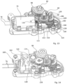
- FIG 13 shows an internal structure of the electromechanical drive 58, in particular a motor-gear assembly, wherein in figure 13 some parts are hidden for better illustration.
- the motor-gear assembly includes, in particular, a motor 74 with electrical connections 76 for applying a motor voltage and a motor output shaft 78.
- the rapid rotation of the electric motor 74 is converted by a gear 80 into a slow rotation of a gear output shaft 82, which drives the drive arm 62 and can be held in particular non-rotatably with the drive arm.
- a motor carrier is provided in the form of a carrier plate 84, which is to be fastened to the lower transmission housing part 60u in a first step.
- the carrier plate 84 is preferably formed from a metal and therefore has high mechanical strength.
- the gear case 60 is formed of a lighter weight material, particularly plastic.
- the support plate 84 is at least partially embedded in the plastic material of the lower gear housing part 60u for secure mounting on the lower gear housing part 60u. Embedding of the support plate 84 can take place during the production of the lower gear housing part 60u, for example during an injection molding process, or subsequently after the hardening of the lower gear housing part 60u.
- the support plate 84 preferably has at least one projection 86 which is embedded in the plastic material of the lower transmission housing part 60u.
- At least one through opening or recess 88 can also be provided in the at least one projection 86, into which plastic material can at least partially penetrate.
- adhesives can be used and the support plate 84 can be glued with its at least one projection 86 in a corresponding recess of the lower transmission housing part 60u.
- a mounting section 90 of the support plate 84 remains free in the installed state and is accessible for mounting the motor 74 .
- the mounting section 90 has second fastening means 92 for fastening the motor 74 to the carrier plate 84 .
- the second fastening means 92 are implemented as holes, to which the motor 74 can be attached with screws 94 can be screwed on.
- the assembly section 90 is preferably plate-shaped and, in the assembled state, lies flat against a plate-shaped section of the motor 74, for example an end face of the motor 74 from which the motor output shaft 78 also emerges. In this way a reliable, stable and very precise positioning of the motor and in particular the motor output shaft 78 is achieved.
- the motor 74 can be assembled by the second fastening means 92 in a relatively simple assembly process.
- first gear wheel 96 Fixedly connected to the transmission output shaft 78 is a first gear wheel 96 which, for reasons of space, is designed as a segmented wheel, so that it is only toothed over its operating angle and is recessed in other peripheral sections.
- the first gear wheel 96 meshes with a small wheel 98 of a first step wheel 100.
- Non-rotatably connected to the small wheel 98 of the first step wheel 100 is a large wheel 102 of the first step wheel 100, which in turn meshes with a small wheel 104 of a second Step wheel 106.
- a large wheel 108 of the second step wheel 106 is designed as a worm wheel and is in engagement with a worm 110 which is arranged on a worm shaft 112 in a rotationally fixed manner.
- the axes of rotation of the first gear wheel 96, the first step wheel 100 and the second step wheel 106 are preferably aligned parallel to one another, while the worm shaft 112 preferably runs at an angle of 90° to the axis of rotation of the second step wheel 106.
- the worm shaft 112 also carries a third gear wheel 114 which in turn meshes with a fourth gear wheel 116 which is arranged on the motor output shaft 78 in a rotationally fixed manner.
- the third gear 114 is preferably larger than the fourth gear 116.
- the rapid rotation of the transmission output shaft 78 via the fourth gear 116, the third gear 114, the worm shaft 112, the worm 110, the large gear 108 of the second stage gear 106, the small gear 104 of the second stage gear 106 , the large gear 102 of the first stage gear 100, the small gear 98 of the first stage gear 100 and the gear wheel 96 are converted into a slower rotation of the transmission output shaft 82.
- the design of the transmission 80 is to be understood as an example; alternatively, transmissions with more or fewer gear stages or with other reduction mechanisms can be used, provided they are suitable for sufficiently adapting the speed of the motor 74 to the desired speed of the transmission output shaft 82 .
- the transmission 80 may further include an overload clutch 118 which may be located at any suitable position in the power path from the engine output shaft 78 to the transmission output shaft 82 as described above.
- an overload clutch 118 which may be located at any suitable position in the power path from the engine output shaft 78 to the transmission output shaft 82 as described above.
- the small and large wheels of the stepped wheels which are normally non-rotatably connected to one another for torque transmission, can be mounted rotatably on one of the stepped wheels in relation to one another. In the present exemplary embodiment, this is implemented with the second step wheel 106 and the overload clutch 118 is arranged between the small wheel 104 and the large wheel 108 of the second step wheel 106 .
- the overload clutch 118 can be embodied, for example, as a slipping clutch and can have a first clutch plate 120, which is fixedly connected to the small wheel 104 of the second step wheel 106, and a second clutch plate 122, which is fixedly connected to the large wheel 108 of the second step wheel 106 is.
- the first clutch plate and the second clutch plate frictionally engage each other so that they transmit rotational force when a differential torque acting between the first clutch plate 120 and the second clutch plate 122 is less than a predetermined overload torque, and rotate relative to each other when the differential torque is greater than the predetermined overload torque.
- the overload torque is preferably adjustable.
- the overload clutch 118 can alternatively or additionally be provided on the first step wheel 100 instead of on the second step wheel 106 .
- the transmission 80 may further include a position sensing mechanism 124 that senses a current position or rotational position of the transmission 80 .
- the position detection mechanism 124 detects a rotational position of the first gear wheel 96.
- the position detection mechanism 124 can have a second gear wheel 126, which is also in mesh with the first gear wheel 96 and, on the other hand, is in turn in mesh with a fifth gear wheel 128, which has a position sensor 130 wears.
- the axes of rotation of the second gear wheel 126 and the fifth gear wheel 128 are in turn parallel to the axis of rotation of the transmission output shaft 82.
- the position sensor 130 can be an encoder known per se, which interacts magnetically or optically with a reading head (not shown) held in place in the housing in order to detect the rotational position of the fifth gear wheel 128, in particular without contact. Accordingly, it is important that the rotational position of the fifth gear wheel 128 can be assigned as precisely as possible to a specific rotational position of the first gear wheel 96 . Hence the requirement to reduce any backlash in the transmission path from the fifth gear 128 to the first gear 96 . According to one aspect of the invention, an anti-game mechanism is used for this purpose, which is described below with reference to FIG Figures 15 and 16 is explained in more detail.
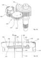
- the anti-backlash mechanism is realized by the second gear wheel 126, which comprises two partial wheels 132, 134 held coaxially to one another.
- the two partial wheels, an upper partial wheel 132 and a lower sub-wheel 134 have the same number of teeth and are both simultaneously engaged with both the first gear wheel 96 and the fifth gear wheel 128.
- the sub-wheels 132, 134 are rotatable relative to one another about the axis of rotation of the second gear wheel 126.
- the relative rotation of the partial wheels 132, 134 is preloaded by a force which is generated by an anti-backlash spring 136 in the present exemplary embodiment.
- the anti-backlash spring 136 is preferably a torsion spring and has one end 138 engaging the upper partial gear 132 and an opposite end (not shown) engaging the lower partial gear 134 .
- the largest part of the anti-backlash spring 136 is preferably accommodated in a space-saving manner in a cavity 140 which is formed between the upper partial wheel 132 and the lower partial wheel 134 .
- the upper part-wheel 132 can have a first recess 142 facing the lower part-wheel 134, which can be designed as a circular or ring-shaped indentation.
- the lower partial wheel 134 can have a second recess 144 which faces the upper partial wheel 132 and which can be designed as a circular and annular depression.
- the engagement of the end 138 of the spring 136 with the upper part gear 132 may be accomplished by inserting the end 138 into an opening 146 of the upper part gear 132 .
- the other end (not shown) of the anti-backlash spring 136 can be maintained in engagement with the lower split gear 134 .
- the flanks of the partial gears 132, 134 lie closely against the flanks of the teeth of the first gear wheel 96 and of the fifth gear 128 so that backlash between the gears is reduced.
- the anti-backlash mechanism of this embodiment can reduce the backlash between the first gear 96 and the fifth gear 128 even further.
- the lower part-wheel 134 is held on a gear shaft 146 of the second gear wheel 126 with less play than the upper part-wheel 132.
- the lower part-wheel 134 can be held on the gear shaft 146 in a rotationally fixed manner or essentially without play so that it can rotate, while the upper partial wheel 132 is mounted with a predetermined clearance d to the transmission shaft 146.
- the transmission shaft 146 could have a larger diameter in the upper axial section than in the lower axial section, so that instead of the upper partial wheel 132 the lower partial wheel 134 then has radial play on the transmission shaft 146 .
- the diameter of an upper central receiving opening 148 in upper partial gear 132, in which gear shaft 146 is received could be larger than a diameter of a lower central receiving opening 150 in lower partial gear 134, in which lower partial gear 134 is attached to the gear shaft 146 is stored.
- the diameter ratios of the central openings 148, 150 can also be reversed here, so that instead of the upper partial wheel 132, the lower partial wheel 134 then has radial play on the transmission shaft 146.
- the result of a play d of the type described above is a predetermined radial play of the upper partial gear 132 relative to the transmission shaft 146 and thus also relative to the lower partial gear 134.
- the radial movement can also be biased by the force of the anti-backlash spring 136, so that the anti-backlash spring 136 has a dual function. Due to the additional radial play d, an even better fit between the upper partial gear 132 and the first gear wheel 96 and the fifth gear wheel 128 can be achieved, so that there is an additional reduction in play. It should be noted, however, that it was found that even without the additional feature of radial play in one of the two partial wheels 132, 134, a very good and significant reduction in play can already be achieved by the relative rotation of the two partial wheels 132, 134.
- figure 17 12 shows the structure of the first step wheel 100.
- the small wheel 98 and the large wheel 102 can each be formed separately from a transmission shaft 152, which forms the axis of rotation of the first step wheel 100.
- the small wheel 98 has a through opening 154 through which the transmission shaft 152 is passed
- the large wheel 102 has a through opening 156 through which the transmission shaft 152 is also passed.
- the small wheel 98 and the large wheel 102 are held against rotation with one another and can be manufactured as separate components and fastened together or can be formed in one piece as an integral structure.
- Small gear 98 and large gear 102 are preferably rotatably supported on gear shaft 152 so that gear shaft 152 can be secured within the housing.
- small gear 98 and the large gear 102 can be made of a material which is different from the material of the transmission shaft 152.
- small gear 98 and large gear 102 can be made of hardened steel in order to transmit large torques and to reduce the wear of the teeth of the wheels, while the gear shaft 152 can be formed of a non-hardened steel to avoid hardening distortion of the gear shaft 152 to counteract.
- the regarding figure 17 The features described above can be implemented alternatively or additionally on the second step wheel 106 or on another step wheel of the transmission 80 .
- rotary power of the motor 74 is translated via the transmission 80 and linkage assembly 52 into movement of the movable member 44 to shift the derailleur 32 to set the desired gear ratio.
- the motor 74 is controlled by an electronic control device 160, which is shown schematically in figure 14 can be seen.
- the electronic control device 160 communicates with the electrical connections 76 (although in figure 14 (e.g., electrical connections 76 are shown disconnected and leading away from electronic controller 160 for purposes of illustration) to apply a motor voltage U to motor 74.
- the electric motor 74 can be operated in a manner known per se, for example via PWM control (pulse width modulation control).
- the electronic control device 160 is also supplied with electrical energy from the battery 64 via the contacts 70 , 72 .
- the electronic control device 160 has receiving means 162 in order to receive control commands from the operating element 36 or from another device.
- signal transmission means known per se can be used here, for example a connection using an electrical cable or, preferably, wireless data transmission.
- the receiving means 162 can include a radio receiver which is set up to receive radio signals from a radio transmitter of the operating element 36 .
- one of the US 2014/0102237 A1 known wireless control are used.
- FIG 18 shows as a schematic block diagram an example of an electronic control device 160 of the type described above, which is implemented on a circuit board 164 and electrically connected to the Motor 74, the battery 64 and the position sensor 130 is connected.
- the circuit board 164 is preferably housed in the transmission housing 60 as well.
- a CPU 166 and a memory 168 connected to the CPU 166 are preferably installed on the circuit board 164 .
- the circuit board 164 can also carry a radio module 170, which forms receiving means 162 of the type described above.
- the circuit board 164 can carry an acceleration sensor 172 which can detect a vibration or movement of the rear derailleur 32 and forward a corresponding signal to the CPU 166 .
- a function switch 174 may be mounted on the circuit board 164 for switching the electronic controller 160 between different modes of operation, resetting, turning it on or off, or the like.
- a display element for example in the form of an LED 176, can be installed on the circuit board 164 and connected to the CPU 166 in order to optically signal operating states of the electronic control device 160.
- a method for controlling the actuating device 10 is explained in more detail below.
- the method can be implemented in particular by a program running in the CPU 166 .
- the radio module 170 receives a switching stage selection signal, for example the switching signal from a driver for setting the rear derailleur in a specific switching stage Sn, selected from the number of available switching stages (eleven switching stages in the exemplary embodiment).
- the electronic control device 160 determines a shift position sn assigned to the shift stage Sn.
- the CPU 166 can read out a shift table stored in the memory 168, which contains an assigned shift position for each available shift stage.
- step S3 the motor 74 is operated with a motor voltage U1 and then the actuating device 10 detects the position s of the movable element 44 in step S4.
- the position s can be determined from an output of the position sensor 130, which indicates the angular position of the first Gear wheel 96 represents. If it is determined in step S5 that the position s of the movable element has reached the switching position sn of the desired switching stage Sn, the switching process is completed in step S21. This corresponds to the case that the switching process could be carried out successfully.
- step S6 it is checked whether the transmission is rotating, which is preferably also done by querying the position sensor 130, e.g. by querying a change over time in the Output of the position sensor 130 can take place. If the transmission does not turn (although the shift position sn has not yet been reached), the method concludes that there is a fault (step S7), caused, for example, by the blocking of the movable element 44, by excessive wear or the like. If, on the other hand, the transmission is still rotating (S6 YES), the method returns to step S4. Steps S4 to S6 thus form a waiting loop for fault detection, in which the position s of the movable element is repeatedly queried and it is determined whether the movable element will eventually reach the desired switching position or whether a fault will occur.
- step S9 the method again detects the position s of the movable element 44 and then checks in step S10 whether the switching position sn has been reached in the meantime or not. If the switching position sn has been reached, the method ends in step S21. Wasn't the switch position yet reached, it is checked again in step S11 whether the transmission is now turning. If the transmission is still stationary (S11 NO), in step S13 it is checked whether the time tz1 measured by the first timer has already exceeded a predetermined first time period ⁇ T1 or not.
- step S9 If the first period of time ⁇ T1 has not yet been exceeded, the method returns to step S9, ie again detects the position s of the movable element 44 and queries a rotation of the transmission, the motor continuing to be operated with the motor voltage U1. Should the transmission move again in the meantime (S11 YES), the timer tz1 is reset to zero in step S12, since the method now assumes that the fault has been rectified and after some time the shift position sn will be reached (S10 YES).
- step S13 If, on the other hand, it is determined in step S13 that the first time period ⁇ T1 has been exceeded, i.e. the shifting process could not be successfully completed even after a time ⁇ T1 has elapsed after the fault was detected (S 13 YES), then in a following step S14 the engine is second motor voltage U2 operated, which is lower than the first motor voltage U1.
- the motor voltages U1 and U2 are adapted to a limit voltage Uc of the overload clutch 118.
- the limit voltage Uc of the overload clutch is the voltage with which the electric motor 74 is to be operated in order to keep the overload clutch 118 straight in the event that the transmission output shaft 82 is blocked trigger.
- step S15 proceeds to step S15 and starts a second timer tz2, ie sets it to 0.
- the first and second timers only represent operands and can be controlled by a common clock or by themselves can only result from subtractions of a continuous clock generator.
- step S16 the position s of the movable element 44 is again detected, whereupon it is checked in step S17 whether the position s of the movable element 44 has reached the switching position sn or not. If the desired switching position has now been reached, the switching process is successfully completed (S21). If the desired shift position sn has not been reached, then in step S18 the method again requests rotation of the transmission. If the transmission is stationary (S18 NO), the method checks in step S20 whether or not the second timer tz2 indicates that a second time period ⁇ T2 has been exceeded.
- step S16 the method returns to step S16 so that the motor continues to be operated with the motor voltage U2 and the position detection and query of the gear rotation are repeated. If it is determined in the meantime that the transmission is turning again (S18 YES), the second timer is reset to zero in a step S19, since it is assumed that the fault has been rectified and the movable element continues to move in the direction of the shift position.
- the method determines that the shifting process has failed and carries out error handling in step S22.
- the error handling can include the output of an error message in the form of an optical or acoustic signal, the transmission of an error message by the radio module 170 or the like. If necessary, after waiting for a further third period of time .DELTA.T3, the method can attempt a new shift, ie return to step S3. Alternatively, the method can wait until another switching signal is sent by the user.
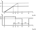
- Figures 20a and 20b show the effect of the switching method described above using two timing diagrams, the two time axes t of Figures 20a and 20b have the same standards, so that Figures 20a and 20b can be compared with each other in relation to the time axis t.
- a normal, trouble-free switching process is represented by a dashed line.
- the movable member 44 moves to the shift position sn corresponding to the desired shift stage and reaches it at a time t4.
- a solid line on the other hand, that is in Figure 20a illustrates the case of a fault in which the movement of the movable element 44 is impeded, for example, by external mechanical influences, wear or dirt.
- the movable element then does not reach the desired switching position sn, but remains at a time t2 at a switching position sf, which is different from sn.
- This disturbance at time t2 can be detected, for example, by the output of the position sensing element 130 indicating that the position of the movable element 44 is no longer changing or is no longer changing in the expected manner.
- the motor voltage U1 at the motor 74 is then maintained for a period of time ⁇ T1.
- the motor 74 is therefore still supplied with full power for the time period ⁇ T1, which can also lead to the overload clutch 118 being triggered if the disturbance persists.
- the motor voltage is reduced to the reduced motor voltage U2 at the time t3, so that the overload clutch 118 remains coupled or is coupled again in any case.
- the motor 74 is then operated with the reduced motor voltage U2 for the period of time ⁇ T2 in order to continue trying to reach the desired switching position sn, in which case, however, a triggering of the overload clutch 118 is avoided.
- the motor voltage is preferably reset to 0 at a time t5, so that the motor 74 is preferably turned off.
- a new shift attempt can then be made, for example, at a point in time t6 when the operator issues a new shift command or a predetermined period of time ⁇ T3 has expired.
- the first period ⁇ T1 can be between 5 ms and 80 ms, preferably between 10 ms and 40 ms, in order to reduce repeated triggering of the overload clutch.
- the second time period ⁇ T2 is preferably longer than the first time period ⁇ T1 and can be between 40 ms and 500 ms, preferably between 60 ms and 200 ms, in order to wait long enough for the fault to be rectified, but at the same time to keep the load on the circuit low .
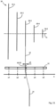
- figure 21 shows schematically the course of the chain 34 between the front chain ring 26, the rear derailleur 32 and the rear sprocket set 30. For reasons of clarity, only five sprockets 30-1 to 30-5 are shown.
- the movable element 44 of the rear derailleur 32 in particular the chain guide wheels 50, move the chain to a position s, so that the chain is ideally aligned with a predetermined sprocket of the sprocket pack or is in any case in an ideal position for smooth chain travel with respect to the pinion is located.
- the rear derailleur 32 moves the chain 34 via the respective sprockets 30-1, 30-2, ...
- Each shift stage is thus a shift position s1, s2, ... assigned.
- This assignment can be in the form of switch position parameters in a switch table ( figure 22 ) be stored, the switch position parameters can be the switch positions themselves or the switch positions can be specifying parameters.
- the shift table may be stored in memory 168 of electronic controller 160 .
- the electronic control device 160 determines an associated value sn from the shifting table in order to set a desired shift stage Sn and controls the motor 74 in such a way that the movable element 44 reaches the shifting position sn.
- the shifting position sn is not directly stored in the shifting table of the present exemplary embodiment. Instead, a standard position (standard position parameter) s0_1, s0_2, ... and a trim amount (trim parameter) x1, x2, ... are stored in the switching table for each switching step.
- the switching position sn then results from the sum of the standard position s0 and the amount of trimming x.
- the switching position s1 of switching stage 1 results from the sum s0_1 + x1 etc. This allows the switching position to be easily reset to a basic setting or factory setting.
- the entries in the shift table can be changed in such a way that two shift position parameters of different shift stages are changed by different amounts.
- a switching table based on the model of figure 22
- the changes in the entries in the switching table can preferably be implemented by control commands received wirelessly, in particular by control commands which are received by the radio module 170 and forwarded to the CPU 166 and the memory 168 .
- a wireless input device in particular a mobile terminal device, can be used for this. Particularly preferred is the use of a smartphone, tablet or similar mobile device on which a predetermined program code (app) is installed, which gives the user the opportunity to directly influence the switching table.
- such a program code can prompt the user to enter a desired switching stage and to enter a trimming amount for this switching stage.
- the program code can also be set up to issue an instruction to the electronic control device 160 to set a specific switching stage.
- the radio module 170 can be set up to transmit data about stored entries in the switching table to the mobile terminal device.
- the program code can give a user the option of gradually increasing or decreasing the trimming amount x for a selected switching stage, with the program code sending an instruction to the electronic control device 160 for each trimming amount set, to move the movable element to the corresponding switching position to be adjusted, which results from the standard position and the trimming amount.
- This enables the user to trim the shifting position of a specific shifting step during operation, that is to say to check the smooth running of the chain and the exact alignment between the chain guide wheel 50 and the sprocket 30-n at the same time.
- the user can then set each of the switching stages, check the switching process or the chain run and the alignment between chain guide wheel 50 and pinion 30-n and, if necessary, make an exact adjustment of the switching position individually for each switching stage.
- checking the chain run and the optimal shifting position can be supported by evaluating the output of acceleration sensor 172.
- acceleration sensor 172 can detect a vibration and send a value representing the strength or amplitude of the vibration to CPU 166 to transfer.
- the CPU 166 can display the value representing the vibration to the user in a suitable form, for example by transmitting the value via the radio module 170 to a receiving unit, in particular a mobile terminal device, on which the the value representing the vibration is displayed, or by appropriate activation of the LED 176, which, in a simple variant, could output information about the strength or amplitude of the vibration by means of a specific flashing code or the like.
- the user can then advantageously use a method for trimming the actuating device, in which he sets a specific switching stage S1 and then sets different trimming amounts x, so that the movable element 44 is moved into switching positions that are in the vicinity of the previously entered switching position, in particular are in the standard switching position S0.
- the user can record the magnitude of the vibration, whereupon he can finally select that trim amount or shift position at which the vibrations were lowest.
- Such a setting corresponds with a good approximation to an optimal switching position.
- the user can finally repeat the process for each switching stage for which he wants the switching position to be adjusted.
- a trimming process for one or more gear stages can be carried out semi-automatically or fully automatically using an in figure 23 illustrated trimming program.
- the trimming program can either run directly on the CPU 166 or alternatively on a control device connected to the electronic control device 160 .
- the trimming program can be installed on a mobile terminal device, such as a smartphone, and can transmit the individual control instructions wirelessly to the CPU 166 via the radio module 170 .
- a switching stage Sn is selected or a switching stage that has already been set is changed.
- the subsequent step S2 based on the switching table ( figure 22 ) determines the switching position sn assigned to the switching stage Sn (for example by adding the standard switching position s0_n to the trim amount xn).
- a value si is selected from an interval ⁇ s, which encloses the shift position sn (sn lies in the interval ⁇ s).
- the interval ⁇ s is preferably less than or equal to an average distance between the shift positions of two adjacent shift stages.
- Steps S3 to S5 are preferably repeated until a predetermined exit determination 1 is met.
- a different value si is selected from the interval ⁇ s, the movable element is moved to the new position si and the vibration vi is measured. This cycle is repeated until exit condition 1 is met.
- exit condition 1 it can be provided that a predetermined number of different positions si have been approached and tested.
- the positions si can be chosen at regular intervals from a smallest value of the interval ⁇ s to a largest value of the interval ⁇ s and the exit condition 1 is met when all positions si have been approached.
- exceeding a predetermined period of time or a user input can be selected as exit condition 1.
- step S7 if the exit condition 1 is met, the vibrations vi measured for the respective position si are compared with one another and a minimum value v_min is determined.
- the position si, at which the minimum value v_min is assumed, is determined in step S8 as the position with the lowest vibration s_min.
- step S9 updates the corresponding shift position parameter in the shift table so that the shift table now results in the value x_min as the new shift position sn for this shift stage Sn (for example, the trim amount xn is set to x_min-s0_n).
- the switching table is therefore updated and rewritten for this switching stage Sn.
- Steps S1 to S9 can be executed repeatedly for a plurality of shift stages Sn until an exit condition 2 is met.
- exit condition 2 can require that all shift stages of the rear derailleur 32 have been selected at least once (step S1) and thus an optimal shift position parameter has been determined for all shift stages by steps S2 to S9.
- the exit condition 2 can request the expiration of a predetermined period of time or request a user input. If exit condition 2 is met, the trimming program ends (step S11).
- FIG. 12 shows a variant of the trimming program described above according to the invention.
- the trimming program is started, for example by user input via the function switch 174 or by a start command which was entered on the mobile terminal and received by the radio module 170 of the electronic control device 160 .
- a position si within the maximum movement range of the movable element 44 from s_min to s_max is then selected in step S'2.
- the electromechanical drive 58 then moves the movable element 44 to the position si in step S'3, whereupon in step S'4 a vibration vi is detected at this position si.
- Steps S'2 to S'4 are executed in the cycle until an exit condition of step S'5 is met.
- the movable element completely runs through the entire range of movement from s_min to s_max once and preferably also runs through the range of movement again in the opposite direction, if necessary the range of movement even more than twice runs through completely, ie sets all possible positions s of the movable element at least once. Accordingly, the exit condition of step S'5 queries whether the entire range of movement of the movable element has been completely traversed the desired number of times.
- the vibrations vi measured at this position si can advantageously be averaged in order to determine a mean vibration vim for each position si, so that the accuracy of the vibration measurement is improved.
- step S'6 the program searches in step S'6 in the data series of the measured values of the vibration vi or vim for minimum values v_min1, v_min2, ... and determines these in step S'7 Positions s_min1, s_min2, . Accordingly, in step S'8, a shift table is updated in such a way that the stored shift positions s1, s2, . . . are replaced by the newly found best shift positions s_min1, s_min2, .
- variants of the trimming device or the trimming method and the trimming program mentioned above allow individual adjustment of individual trimming amounts or individual switching positions of the respective switching stages.
- variants of the invention are also considered to be advantageous in which a single trimming process affects the trim amounts of all switching stages or essentially all switching stages at the same time, albeit to a different extent.
- a particularly simple trimming function is achieved in order to compensate for misalignments between the rear derailleur 32 and the sprocket set 30, which continuously increase or decrease from sprocket to sprocket.
- An example of this is an adjustment in the position of the movable element 44 as a result of an axial force exerted by the chain 34 .
- this tensile force increases, with the extent of the associated misalignment between rear derailleur 32 and sprocket set 30 also increasing with increasing offset between sprocket and front chainring 24, i.e. with increasing inclination of chain 34.
- the electronic controller 160 can then be set up to change the trimming amounts x1, x2, .
- the adjusting device can advantageously be set up to allow the trim amounts to increase as the distance between the shift positions and the shift position sn increases.
- a trimming process with such predefined sets of trimming amounts can be carried out in the in figure 24 follow the illustrated sequence of steps.
- This in figure 25 The trimming procedure illustrated can be carried out, for example, after the initial installation of a rear derailleur on a bicycle, during maintenance work or after replacing components of the bicycle.
- a neutral gear stage SN is a specific shift stage, usually a middle shift stage, in which there is essentially no chain oblique position, i.e. a pinion which is arranged at approximately the same axial height as the chainring.
- step S101 it is checked in step S101 whether the shift position set by the rear derailleur is correct, i.e. whether the chain guide wheel is set at the correct axial height relative to the corresponding sprocket.
- the synchronization of the chain can be checked or a vibration of the rear derailleur can be detected, as described above.
- a trimming procedure 1 (step S102) is carried out, which can essentially correspond to a trimming process known per se, for example a trimming process in which all shift positions are changed by essentially the same amount.
- the trimming procedure 1 is completed when the correct shift position for the neutral shift stage SN is reached.
- step S103 the rear derailleur is set to an extreme shift stage, for example the highest shift stage or the lowest shift stage (step S103).
- step S104 it is checked again whether the switching position of the movable element is correct, ie whether the chain guide wheel is in the correct position relative to the sprocket. If this is not the case (step S104 NO), a trimming procedure 2 is initiated, which works with different trimming amounts for the different shift positions.
- a set of trimming amounts can be selected in which the trim amounts are adjusted simultaneously, but by different amounts.
- a number of predefined sets of trim amounts are available, which can be optionally adjusted.
- the adjustment process can be carried out by a user manually or by an electronic command to change the shift table. Once a suitable amount of trim has been found that will ensure correct positioning in the selected gear ratio, the trimming process finally ends in step S106. If desired, the method S100 to S106 can be repeated for different shift stages, in particular different extreme shift stages, in order to find the appropriate trim amounts.
Landscapes
- Engineering & Computer Science (AREA)
- Chemical & Material Sciences (AREA)
- Combustion & Propulsion (AREA)
- Transportation (AREA)
- Mechanical Engineering (AREA)
- Transmission Devices (AREA)
- Gear-Shifting Mechanisms (AREA)
- Gear Transmission (AREA)
- Connection Of Motors, Electrical Generators, Mechanical Devices, And The Like (AREA)
- Automatic Cycles, And Cycles In General (AREA)
- Steering Devices For Bicycles And Motorcycles (AREA)
Applications Claiming Priority (2)
| Application Number | Priority Date | Filing Date | Title |
|---|---|---|---|
| DE102018207493.3A DE102018207493A1 (de) | 2018-05-15 | 2018-05-15 | Stelleinrichtung für ein Fahrrad und Verfahren zur Steuerung oder Einstellung solcher Stelleinrichtungen |
| EP19000233.7A EP3578451B1 (fr) | 2018-05-15 | 2019-05-06 | Dispositif de réglage pour une bicyclette et procédé de commande ou de réglage d'un tel dispositif de réglage |
Related Parent Applications (1)
| Application Number | Title | Priority Date | Filing Date |
|---|---|---|---|
| EP19000233.7A Division EP3578451B1 (fr) | 2018-05-15 | 2019-05-06 | Dispositif de réglage pour une bicyclette et procédé de commande ou de réglage d'un tel dispositif de réglage |
Publications (2)
| Publication Number | Publication Date |
|---|---|
| EP4186779A2 true EP4186779A2 (fr) | 2023-05-31 |
| EP4186779A3 EP4186779A3 (fr) | 2023-08-02 |
Family
ID=66554099
Family Applications (2)
| Application Number | Title | Priority Date | Filing Date |
|---|---|---|---|
| EP19000233.7A Active EP3578451B1 (fr) | 2018-05-15 | 2019-05-06 | Dispositif de réglage pour une bicyclette et procédé de commande ou de réglage d'un tel dispositif de réglage |
| EP23020013.1A Pending EP4186779A3 (fr) | 2018-05-15 | 2019-05-06 | Dispositif de réglage pour une bicyclette et procédé de commande ou de réglage de tels dispositifs de réglage |
Family Applications Before (1)
| Application Number | Title | Priority Date | Filing Date |
|---|---|---|---|
| EP19000233.7A Active EP3578451B1 (fr) | 2018-05-15 | 2019-05-06 | Dispositif de réglage pour une bicyclette et procédé de commande ou de réglage d'un tel dispositif de réglage |
Country Status (5)
| Country | Link |
|---|---|
| US (3) | US11312449B2 (fr) |
| EP (2) | EP3578451B1 (fr) |
| CN (1) | CN110481699B (fr) |
| DE (1) | DE102018207493A1 (fr) |
| TW (1) | TWI808152B (fr) |
Families Citing this family (28)
| Publication number | Priority date | Publication date | Assignee | Title |
|---|---|---|---|---|
| US9394030B2 (en) * | 2012-09-27 | 2016-07-19 | Sram, Llc | Rear derailleur |
| DE102018001253A1 (de) * | 2017-03-20 | 2018-09-20 | Sram Deutschland Gmbh | Hinteres Schaltwerk zur koaxialen Montage |
| US11498643B2 (en) * | 2019-02-26 | 2022-11-15 | Shimano Inc. | Bicycle electric derailleur |
| DE102020000827A1 (de) * | 2019-04-25 | 2020-10-29 | Sram Deutschland Gmbh | Elektromechanisches Schaltwerk zur koaxialen Montage |
| PL3730394T3 (pl) * | 2019-04-25 | 2024-03-04 | Sram Deutschland Gmbh | Elektromechaniczna tylna przerzutka rowerowa do montażu współosiowego |
| US11840315B2 (en) | 2019-05-02 | 2023-12-12 | Sram, Llc | Gear changer adjustment and device |
| TWI729556B (zh) * | 2019-11-06 | 2021-06-01 | 天心工業股份有限公司 | 自行車之後變速器 |
| TWI712547B (zh) * | 2019-11-06 | 2020-12-11 | 天心工業股份有限公司 | 自行車之後變速器 |
| TWI729557B (zh) * | 2019-11-06 | 2021-06-01 | 天心工業股份有限公司 | 自行車之後變速器 |
| TWI712540B (zh) * | 2019-12-02 | 2020-12-11 | 彥豪金屬工業股份有限公司 | 撥鏈位置設定系統及其方法 |
| TWI716290B (zh) * | 2020-03-04 | 2021-01-11 | 彥豪金屬工業股份有限公司 | 自行車組件及其配對方法 |
| US11554832B2 (en) * | 2020-09-11 | 2023-01-17 | Shimano Inc. | Bicycle derailleur and method of controlling bicycle derailleur |
| US11926394B2 (en) * | 2020-09-11 | 2024-03-12 | Shimano Inc. | Bicycle derailleur |
| US20220297798A1 (en) * | 2021-03-16 | 2022-09-22 | Tien Hsin Industries Co., Ltd. | Electronic derailleur |
| US12384491B2 (en) * | 2021-05-07 | 2025-08-12 | Sram, Llc | Bicycle derailleur |
| US11479323B2 (en) * | 2021-07-06 | 2022-10-25 | Hazem Nihad Hamed | Automatic bicycle shifter and shifting cable actuator |
| IT202100024725A1 (it) * | 2021-09-28 | 2023-03-28 | Campagnolo Srl | Equipaggiamento di bicicletta dotato di unita’ di alimentazione elettrica |
| IT202100024800A1 (it) | 2021-09-28 | 2023-03-28 | Campagnolo Srl | Equipaggiamento di bicicletta elettronico |
| JP2023051371A (ja) * | 2021-09-30 | 2023-04-11 | 株式会社シマノ | 人力駆動車用のコンポーネント |
| TWI786971B (zh) * | 2021-12-01 | 2022-12-11 | 彥豪金屬工業股份有限公司 | 變速器的控制方法及變速控制系統 |
| US12358592B2 (en) | 2021-12-09 | 2025-07-15 | Sram, Llc | Bicycle derailleur |
| US11787505B1 (en) | 2022-04-12 | 2023-10-17 | Shimano Inc. | Linkage and derailleur for human-powered vehicle |
| TWI839826B (zh) * | 2022-08-31 | 2024-04-21 | 凱納股份有限公司 | 電動輔助自行車之管理系統及其管理方法 |
| CN117719623A (zh) * | 2022-09-16 | 2024-03-19 | 株式会社岛野 | 用于自行车部件的马达单元和拨链器 |
| TWI848488B (zh) * | 2022-12-28 | 2024-07-11 | 彥豪金屬工業股份有限公司 | 自行車後變速器 |
| US12275491B2 (en) * | 2023-08-28 | 2025-04-15 | Shimano Inc. | Bicycle motor unit and bicycle derailleur |
| US12214845B1 (en) * | 2023-10-18 | 2025-02-04 | Shimano Inc. | Electric device and control system of human-powered vehicle and non-transitory computer-readable storage medium |
| US12617492B1 (en) * | 2025-02-26 | 2026-05-05 | Tien Hsin Industries Co., Ltd. | Electronic derailleur |
Citations (3)
| Publication number | Priority date | Publication date | Assignee | Title |
|---|---|---|---|---|
| DE4212320A1 (de) | 1992-04-13 | 1993-10-14 | Fichtel & Sachs Ag | Elektrische Stellvorrichtung |
| US20140102237A1 (en) | 2012-10-11 | 2014-04-17 | Sram, Llc | Electronic shifting systems and methods |
| US20150111675A1 (en) | 2013-10-23 | 2015-04-23 | Sram, Llc | Electromechanical rear derailleur |
Family Cites Families (68)
| Publication number | Priority date | Publication date | Assignee | Title |
|---|---|---|---|---|
| US2607238A (en) * | 1951-04-28 | 1952-08-19 | Oak Mfg Co | Gear drive |
| US3359819A (en) * | 1966-04-25 | 1967-12-26 | Leo J Veillette | Bidirectional step torque filter with zero backlash characteristic |
| US3809486A (en) * | 1971-04-06 | 1974-05-07 | Amana Refrigeration Inc | Mechanical coupling arrangement |
| US5059158A (en) * | 1990-05-08 | 1991-10-22 | E.B.T., Inc. | Electronic transmission control system for a bicycle |
| US5213548A (en) * | 1992-03-02 | 1993-05-25 | Colbert Ralph G | Gear shifting system for derailleur equipped bicycle |
| DE4212319A1 (de) * | 1992-04-13 | 1993-10-14 | Fichtel & Sachs Ag | Steuervorrichtung |
| IT1276417B1 (it) * | 1995-06-07 | 1997-10-31 | Campagnolo Srl | "dispositivo di cambio di velocita' per biciclette a controllo elettro nico" |
| US5599244A (en) * | 1995-08-14 | 1997-02-04 | Ethington; Russell A. | Automatic transmission shifter for velocipedes |
| US6109129A (en) * | 1997-05-08 | 2000-08-29 | Cummins Engine Company, Inc. | Apparatus and method for adjusting a gear |
| US5870928A (en) * | 1997-05-08 | 1999-02-16 | Cummins Engine Company, Inc. | Anti-lash gear with alignment device |
| US6162140A (en) * | 1998-12-18 | 2000-12-19 | Shimano, Inc. | Motor driven derailleur |
| US6148684A (en) * | 1999-03-10 | 2000-11-21 | Heidelberger Druckmaschinen Aktiengesellschaft | Anti-backlash gear |
| US6726586B2 (en) * | 2001-11-09 | 2004-04-27 | Shimano Inc. | Motorized bicycle actuator assembly |
| JP3654868B2 (ja) * | 2002-02-21 | 2005-06-02 | 株式会社シマノ | 自転車用変速制御装置及び自転車用変速制御方法 |
| US6781510B2 (en) * | 2002-07-24 | 2004-08-24 | Shimano, Inc. | Bicycle computer control arrangement and method |
| US6931958B2 (en) * | 2002-08-23 | 2005-08-23 | Shimaro, Inc. | Apparatus for controlling first and second bicycle transmissions |
| US20040089089A1 (en) * | 2002-11-08 | 2004-05-13 | Stevens Carlos J. | Anti-backlash method and system for multiple mesh gear train |
| US6945888B2 (en) * | 2002-11-21 | 2005-09-20 | Shimano, Inc. | Combined analog and digital derailleur position processing apparatus |
| ATE353814T1 (de) * | 2002-12-06 | 2007-03-15 | Campagnolo Srl | Elektronisch, servobetätigte fahrradgangschaltung und zugehöriges verfahren |
| ATE521530T1 (de) * | 2002-12-06 | 2011-09-15 | Campagnolo Srl | Elektronisch, servobetätigte fahrradgangschaltung und zugehöriges verfahren |
| JP3703810B2 (ja) * | 2003-02-25 | 2005-10-05 | 株式会社シマノ | 自転車用自動変速制御装置 |
| DE60302782T2 (de) * | 2003-07-24 | 2006-07-13 | Campagnolo S.R.L. | Verfahren zum Schalten eines Fahrradgetriebes mit elektrischem Hilfsantrieb und Schaltvorrichtung |
| US7290458B2 (en) * | 2004-02-24 | 2007-11-06 | Shimano, Inc. | Bicycle derailleur with a motor disposed within a linkage mechanism |
| US7467567B2 (en) * | 2004-02-24 | 2008-12-23 | Shimano, Inc. | Gear reduction apparatus for a bicycle component |
| JP2005280408A (ja) * | 2004-03-29 | 2005-10-13 | Shimano Inc | 自転車用ディレーラ制御装置及び制御方法 |
| JP2005297655A (ja) * | 2004-04-08 | 2005-10-27 | Shimano Inc | 自転車用変速制御装置及びフロントディレーラの制御方法 |
| US7306531B2 (en) * | 2004-04-23 | 2007-12-11 | Shimano Inc. | Electric bicycle derailleur |
| JP2005313748A (ja) * | 2004-04-28 | 2005-11-10 | Shimano Inc | 自転車用変速制御装置 |
| ITMI20061295A1 (it) * | 2006-07-04 | 2008-01-05 | Campagnolo Srl | Medoto e sistema di erogazione di energia elettrica da una unita' di alimentazione a batteria |
| US7942768B2 (en) * | 2008-01-28 | 2011-05-17 | Shimano, Inc. | Electrically operated derailleur that re-engages a disengaged derailleur force overload clutch |
| EP2088071B1 (fr) * | 2008-02-06 | 2013-12-11 | Campagnolo S.r.l. | Procédé pour contrôler électroniquement un changement de vitesses de bicyclette et système électronique de bicyclette |
| US7805268B2 (en) * | 2008-02-20 | 2010-09-28 | Shimano Inc. | Bicycle component calibration device |
| AT508701B1 (de) * | 2010-06-23 | 2011-05-15 | Miba Sinter Austria Gmbh | Zahnradanordnung |
| AT510283B1 (de) * | 2010-09-29 | 2012-03-15 | Miba Sinter Austria Gmbh | Zahnradanordnung |
| US8979683B2 (en) * | 2012-01-31 | 2015-03-17 | Shimano Inc. | Bicycle electric actuator unit |
| US8955395B2 (en) * | 2012-05-24 | 2015-02-17 | Ronald Greggory Bjork | Magneto cyclist power sensor |
| ITMI20121279A1 (it) * | 2012-07-23 | 2014-01-24 | Campagnolo Srl | Metodo per controllare elettronicamente un cambio di bicicletta e cambio di bicicletta servoassistito elettronicamente |
| US9394030B2 (en) * | 2012-09-27 | 2016-07-19 | Sram, Llc | Rear derailleur |
| US9802669B2 (en) * | 2012-10-11 | 2017-10-31 | Sram, Llc | Electronic shifting systems and methods |
| AT513246B1 (de) * | 2012-10-25 | 2014-03-15 | Miba Sinter Austria Gmbh | Zahnradanordnung |
| US9726216B2 (en) * | 2013-02-04 | 2017-08-08 | Shimano Inc. | Cable adjusting unit |
| AT513613B1 (de) * | 2013-02-08 | 2014-06-15 | Miba Sinter Austria Gmbh | Zahnradanordnung |
| US9555856B2 (en) * | 2013-03-25 | 2017-01-31 | Shimano Inc. | Electric front derailleur |
| US9008923B2 (en) * | 2013-04-05 | 2015-04-14 | Shimano Inc. | Bicycle derailleur adjusting apparatus |
| ITMI20130895A1 (it) * | 2013-05-31 | 2014-12-01 | Campagnolo Srl | Sistema elettronico di bicicletta |
| ITMI20131064A1 (it) * | 2013-06-26 | 2014-12-27 | Campagnolo Srl | Sistema elettronico di bicicletta |
| JP2015027861A (ja) * | 2013-07-05 | 2015-02-12 | 株式会社シマノ | 自転車制御システム |
| US20150020629A1 (en) * | 2013-07-17 | 2015-01-22 | Achates Power, Inc. | Gear Noise Reduction in Opposed-Piston Engines |
| ITMI20131825A1 (it) * | 2013-11-04 | 2015-05-05 | Campagnolo Srl | Deragliatore ad azionamento motorizzato per un cambio di bicicletta |
| ITMI20131902A1 (it) * | 2013-11-15 | 2015-05-16 | Campagnolo Srl | Sistema elettronico di bicicletta |
| US20150284049A1 (en) * | 2014-04-04 | 2015-10-08 | Sram, Llc | Control assembly for a wireless electromechanical bicycle shifting system |
| EP2979970B1 (fr) * | 2014-08-01 | 2017-09-13 | Campagnolo S.R.L. | Système électronique de bicyclette et procédé associé |
| US9772030B2 (en) * | 2014-08-04 | 2017-09-26 | Achates Power, Inc. | Split gear assembly with one-way roller clutch for controlling backlash in opposed-piston engines |
| US20160039497A1 (en) * | 2014-08-08 | 2016-02-11 | Armando Mastracci | Gear Selection for Multi-Geared, Pedal-Operated Vehicles |
| US9751590B2 (en) * | 2014-08-15 | 2017-09-05 | Sram, Llc | Bicycle rear derailleur with a damper assembly |
| US9278728B1 (en) * | 2014-10-29 | 2016-03-08 | Shimano Inc. | Bicycle shifting control apparatus and method of controlling derailleur |
| CN107428393B (zh) * | 2015-02-13 | 2020-05-15 | 斯沃莱茨德塞格尔公司 | 电动自行车传动系统、方法和设备 |
| US10029754B2 (en) * | 2015-03-06 | 2018-07-24 | Shimano Inc. | Bicycle electrical system |
| US20160288877A1 (en) * | 2015-04-01 | 2016-10-06 | Wick Werks, LLC | Bicycle derailleur with automatic alignment, and methods for automatic derailleur alignment |
| ITUB20152302A1 (it) * | 2015-07-20 | 2017-01-20 | Campagnolo Srl | Sistema elettronico di bicicletta |
| US9944350B2 (en) * | 2016-01-11 | 2018-04-17 | Sram, Llc | Chain guide sensor and methods of controling a bicycle |
| US9809276B2 (en) * | 2016-02-29 | 2017-11-07 | Shimano Inc. | Electric bicycle derailleur control system |
| US9714067B1 (en) * | 2016-02-29 | 2017-07-25 | Shimano Inc. | Bicycle chain device |
| TWI648198B (zh) * | 2016-08-10 | 2019-01-21 | 天心工業股份有限公司 | 自行車及其變速裝置 |
| JP2018114959A (ja) * | 2017-01-20 | 2018-07-26 | 株式会社シマノ | 自転車用変速機キャリブレーションシステム、自転車用シートポストキャリブレーションシステム、および、自転車用サスペンションキャリブレーションシステム |
| US10577053B2 (en) * | 2017-06-06 | 2020-03-03 | Sram, Llc | Damper for a bicycle component |
| US10882587B2 (en) * | 2017-06-26 | 2021-01-05 | Sram, Llc | Damper for a bicycle component |
| TWI804619B (zh) * | 2018-05-11 | 2023-06-11 | 義大利商坎帕克諾羅公司 | 設有電氣/電子系統的自行車曲柄臂 |
-
2018
- 2018-05-15 DE DE102018207493.3A patent/DE102018207493A1/de active Pending
-
2019
- 2019-04-09 TW TW108112366A patent/TWI808152B/zh active
- 2019-05-06 EP EP19000233.7A patent/EP3578451B1/fr active Active
- 2019-05-06 EP EP23020013.1A patent/EP4186779A3/fr active Pending
- 2019-05-15 US US16/412,667 patent/US11312449B2/en active Active
- 2019-05-15 CN CN201910404205.9A patent/CN110481699B/zh active Active
-
2022
- 2022-03-22 US US17/700,914 patent/US11731733B2/en active Active
-
2023
- 2023-06-30 US US18/345,024 patent/US12485995B2/en active Active
Patent Citations (3)
| Publication number | Priority date | Publication date | Assignee | Title |
|---|---|---|---|---|
| DE4212320A1 (de) | 1992-04-13 | 1993-10-14 | Fichtel & Sachs Ag | Elektrische Stellvorrichtung |
| US20140102237A1 (en) | 2012-10-11 | 2014-04-17 | Sram, Llc | Electronic shifting systems and methods |
| US20150111675A1 (en) | 2013-10-23 | 2015-04-23 | Sram, Llc | Electromechanical rear derailleur |
Also Published As
| Publication number | Publication date |
|---|---|
| TWI808152B (zh) | 2023-07-11 |
| US12485995B2 (en) | 2025-12-02 |
| TW201946834A (zh) | 2019-12-16 |
| EP3578451A3 (fr) | 2020-03-04 |
| US20230348019A1 (en) | 2023-11-02 |
| CN110481699A (zh) | 2019-11-22 |
| CN110481699B (zh) | 2023-05-05 |
| US11731733B2 (en) | 2023-08-22 |
| US20190351971A1 (en) | 2019-11-21 |
| US11312449B2 (en) | 2022-04-26 |
| EP4186779A3 (fr) | 2023-08-02 |
| US20220212753A1 (en) | 2022-07-07 |
| EP3578451B1 (fr) | 2023-01-18 |
| DE102018207493A1 (de) | 2019-11-21 |
| EP3578451A2 (fr) | 2019-12-11 |
Similar Documents
| Publication | Publication Date | Title |
|---|---|---|
| EP3578451B1 (fr) | Dispositif de réglage pour une bicyclette et procédé de commande ou de réglage d'un tel dispositif de réglage | |
| DE60308969T2 (de) | Motoreinheit für eine Hilfsschaltvorrichtung in einer Fahrradgangschaltung | |
| DE69129656T2 (de) | Elektronisches steuersystem für das getriebe eines fahrrads | |
| DE102013017194B4 (de) | Vorderes Schaltwerk | |
| DE19501283C2 (de) | Kettenschaltungsvorrichtung für Fahrräder | |
| DE102012016312B4 (de) | Elektrische Servolenkungsvorrichtung | |
| DE60220233T2 (de) | Motorisiertes Verstellungssystem für Fahrrad | |
| DE4212320A1 (de) | Elektrische Stellvorrichtung | |
| DE10114937A1 (de) | Verfahren zum Steuern der Gangschaltung an einem Zweirad und entsprechendes System und entsprechende Komponenten | |
| EP3700799B1 (fr) | Colonne de direction pour véhicule automobile | |
| DE102017103733A1 (de) | Elektrisches Fahrradumwerfersteuerungssystem | |
| DE102018100918A1 (de) | Fahrradsteuervorrichtung und Verfahren zum Steuern eines Fahrrads | |
| DE4422845A1 (de) | Motorgetriebene Kettenschaltungsanordnung für Fahrräder | |
| DE4134794A1 (de) | Weggeber fuer einen stellantrieb, insbesondere in einem fahrzeug | |
| DE102017003163A1 (de) | Fahrradschaltwerkapparat und fahrradantriebseinheit | |
| DE102020212445A1 (de) | Schaltwerk eines von Menschen angetriebenen Gefährts | |
| DE69717553T2 (de) | Fahrrad mit Hilfsmotor | |
| DE3802560A1 (de) | Umwerfer fuer ein fahrrad | |
| WO2014198265A1 (fr) | Système de propulsion de bicyclette | |
| WO2023180538A1 (fr) | Processeur et procédé, en particulier procédé mis en œuvre par ordinateur, pour commander une boîte de vitesses de moyeu d'une bicyclette avec un moteur auxiliaire et système de changement de vitesses avec un processeur de ce type | |
| DE102020212362A1 (de) | Schaltwerk eines von menschen angetriebenen gefährts | |
| DE102023206745A1 (de) | Fahrradumwerfer | |
| DE102020212363A1 (de) | Schaltwerk eines von menschen angetriebenen gefährts | |
| WO2024170552A1 (fr) | Direction à commande électrique "steer-by-wire" pour un véhicule automobile | |
| DE102021211316A1 (de) | Steuersystem eines von menschen angetriebenen gefährts |
Legal Events
| Date | Code | Title | Description |
|---|---|---|---|
| PUAI | Public reference made under article 153(3) epc to a published international application that has entered the european phase |
Free format text: ORIGINAL CODE: 0009012 |
|
| STAA | Information on the status of an ep patent application or granted ep patent |
Free format text: STATUS: THE APPLICATION HAS BEEN PUBLISHED |
|
| AC | Divisional application: reference to earlier application |
Ref document number: 3578451 Country of ref document: EP Kind code of ref document: P |
|
| AK | Designated contracting states |
Kind code of ref document: A2 Designated state(s): AL AT BE BG CH CY CZ DE DK EE ES FI FR GB GR HR HU IE IS IT LI LT LU LV MC MK MT NL NO PL PT RO RS SE SI SK SM TR |
|
| PUAL | Search report despatched |
Free format text: ORIGINAL CODE: 0009013 |
|
| AK | Designated contracting states |
Kind code of ref document: A3 Designated state(s): AL AT BE BG CH CY CZ DE DK EE ES FI FR GB GR HR HU IE IS IT LI LT LU LV MC MK MT NL NO PL PT RO RS SE SI SK SM TR |
|
| RIC1 | Information provided on ipc code assigned before grant |
Ipc: B62M 9/122 20100101AFI20230626BHEP |
|
| STAA | Information on the status of an ep patent application or granted ep patent |
Free format text: STATUS: REQUEST FOR EXAMINATION WAS MADE |
|
| 17P | Request for examination filed |
Effective date: 20240404 |
|
| STAA | Information on the status of an ep patent application or granted ep patent |
Free format text: STATUS: EXAMINATION IS IN PROGRESS |
|
| 17Q | First examination report despatched |
Effective date: 20241216 |