US5213548A - Gear shifting system for derailleur equipped bicycle - Google Patents
Gear shifting system for derailleur equipped bicycle Download PDFInfo
- Publication number
- US5213548A US5213548A US07/844,740 US84474092A US5213548A US 5213548 A US5213548 A US 5213548A US 84474092 A US84474092 A US 84474092A US 5213548 A US5213548 A US 5213548A
- Authority
- US
- United States
- Prior art keywords
- bicycle
- microcontroller
- limits
- signal
- speed
- Prior art date
- Legal status (The legal status is an assumption and is not a legal conclusion. Google has not performed a legal analysis and makes no representation as to the accuracy of the status listed.)
- Expired - Lifetime
Links
Images


Classifications
-
- B—PERFORMING OPERATIONS; TRANSPORTING
- B62—LAND VEHICLES FOR TRAVELLING OTHERWISE THAN ON RAILS
- B62M—RIDER PROPULSION OF WHEELED VEHICLES OR SLEDGES; POWERED PROPULSION OF SLEDGES OR SINGLE-TRACK CYCLES; TRANSMISSIONS SPECIALLY ADAPTED FOR SUCH VEHICLES
- B62M25/00—Actuators for gearing speed-change mechanisms specially adapted for cycles
- B62M25/08—Actuators for gearing speed-change mechanisms specially adapted for cycles with electrical or fluid transmitting systems
Definitions
- the present invention relates to an improved automatic gear shifting system having automatic and manual modes of operation for use on derailleur equipped bicycles and more particularly, to an improved derailleur shifter where, in the automatic mode of operation the gear ratio between the driving and driven gears can automatically varied in response to wheel speed and crank speed sensors, the output signals therefrom and signals from an operator's control panel being processed by a microcontroller, and where, in the manual mode of operation, the bicycle user can change the gear ratio by activating a pushbutton on the control panel.
- the Chappell device comprises a fixed frame connected arm, a shifter arm moveable relative to the fixed arm, the moveable shifter arm carrying a chain follower in sliding engagement with the bicycle chain, a spring biasing means between the two arms urging the follower to depress the chain and a cable interconnected between the moveable shifter arm and the derailleur to automatically shift the derailleur in response to chain tension as sensed by the follower.
- indexing of the derailleur to move the chain between the cluster gears is automatically accomplished without the conscious effort on part of the rider.
- U.S. Pat. No. 4,599,079 also to Chappell, discloses a similar device to that set forth in U.S. Pat. No. 4,693,700 and provides a different bicycle chain tension sensing mechanism.
- U.S. Pat. No. 4,857,035 to Anderson discloses an automatic bicycle power transmission system, the bicycle having only a single sprocket mounted at the rear wheel without a derailleur system.
- Chappell and Van Dyke patents disclose an automatic derailleur type shifting mechanism
- the systems require a complicated and expensive array of mechanical parts.
- shifting is dependent upon the tension of the bicycle chain, which, in itself, provides an inefficient way for controlling the derailleur.
- neither the velocity of the bicycle or the rotational speed of the pedals is utilized directly to control the bicycle gear ratio, two parameters which more closely relate to the bicycle rider and which, would prove to be an effective way of providing the most efficient gear ratio for a bicycle rider.
- the present invention provides a dual mode gear shifting system for moving the chain on a multi-speed bicycle between rear sprockets on the rear freewheel and chainwheels on the front crank on a multi-speed bicycle.
- the system will accommodate freewheels with six, seven or eight sprockets and front cranks with two or three chainwheels.
- the system comprises a microcontroller, a front derailleur and servomotor assembly, a rear derailleur and servomotor assembly, a wheel speed sensor assembly, a crank speed sensor assembly, a mode selector assembly, or control panel, which contains the microcontroller, a power supply and a cable assembly.
- the microcontroller receives inputs from the mode selector, wheel speed and crank speed sensors and provides drive position signals to the front and rear derailleur assemblies servo motors.
- the microcontroller also provides an indication of the power supply, typically a battery, condition.
- the front derailleur and servomotor assembly converts position drive signals from the microcontroller to control the front derailleur in a manner such that the bicycle chain is positioned onto the selected chainwheel.
- the rear derailleur and servomotor assembly converts position drive signals from the microcontroller to position the rear derailleur in a manner such that the bicycle chain is positioned onto the selected rear sprocket.
- the wheel speed sensor senses the speed of the bicycle and provides an electrical output to the microcontroller in the automatic mode of operation. In this mode, the crank speed sensor senses the speed of the crank and also provides an electrical output to the microcontroller.
- the mode selector assembly is actuated by the bicycle user to select the automatic gear shifting system mode of operation or the manual mode of operation and provides the selected modes and signals for the microcontroller.
- the mode selector assembly also has a display portion which provides an indication of the battery condition provided by the microcontroller output. Means are provided for mounting the microcontroller and the battery power supply within the mode selector. The battery power supply provides power to all of the electrical components of the system.
- the cable assembly connects the speed sensors and the front and rear derailleur servo motors to the mode selector, microcontroller and battery power supply.
- the bicycle rider In the manual mode of operation, the bicycle rider is able to directly select a chainwheel and rear sprocket through pushbuttons on the mode selector.
- the bicycle rider chooses a crank speed range and the gear ratio is automatically selected to maintain crank speed within the selected range.
- the present invention thus provides a dual mode gear shifting system which utilizes a microcontroller which has a selected algorithm to adjust the bicycle gear ratios to maintain pedaling rate, or cadence, within a predetermined range.
- a microcontroller which has a selected algorithm to adjust the bicycle gear ratios to maintain pedaling rate, or cadence, within a predetermined range.
- the rotational ratio of the wheel and crank are compared to prestored gear ratios to determine if the cyclist is pedaling or coasting before a shift is allowed. This prevents a coasting cadence from causing an unwanted downshift and enables the most efficient gear ratio to be selected.
- selecting a particular pushbutton on the mode selector causes the microcontroller to adjust the bicycle chain position on both the front chainwheels and the rear sprockets in a sequentical manner to either a larger or smaller gear until the bicycle user has determined that a desirable gear ratio has been reached.
- the invention enables a bicycle user, instead of adjusting two gear levers while operating the bicycle to reach a desired gear ratio, the standard technique in current multiple gear bicycles, to simply push a button to accomplish the same result.
- the present invention discloses a dual mode gear shifting system
- teachings of the present invention can utilized in providing a bicycle which utilizes either the automatic or manual modes of operation and thus provide a single gear shifting mode of operation.
- the present invention also provides a simplified technique of improving bicycle riding efficiency while minimizing the use of additional mechanical components which would normally increase the weight and complexity of the system.
- FIG. 1 is a partial side elevational view of an automatic derailleur shifter for a bicycle transmission in accordance with the teachings of the present invention
- FIG. 2 is a view along line 2--2 of FIG. 1 showing the handle bar mounted mode selector device
- FIG. 3 is a detail of the rear derailleur system with the servo motor assembly mounted thereto;
- FIG. 4 is a view along line 4--4 of FIG. 3;
- FIG. 5 is a view along line 5--5 of FIG. 3 with the bicycle chain on the small sprocket;
- FIG. 6 is a view along line 6--6 of FIG. 3 with the bicycle chain on the large sprocket;
- FIG. 7 is a detail of the front derailleur system with the servomotor assembly mounted thereto;
- FIG. 8 is a view along line 8--8 of FIG. 7;
- FIG. 9 is a view along line 9--9 of FIG. 8 with the bicycle chain on the larger chainwheel;
- FIG. 10 is a view along line 9--9 of FIG. 8 with the bicycle chain on the small chainwheel;
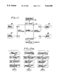
- FIG. 11 is a block diagram of the control system of the present invention.
- FIG. 12(a)-12(g) are flow charts for the microcontroller shown in FIG. 11.
- the gear shifting system of the present invention comprises a microcontroller (although the term "microcontroller” is utilized and a definition is set forth hereinafter, other terms which can be utilized to characterize the function of the programmed control device are "microprocessor” and “microcomputer”), a plurality of sensors which allow the microcontroller to determine the status of the bicycle, at least two actuators to drive the bicycle derailleurs (shift mechanisms), and a mode selector assembly, hereinafter referred to as a control panel, to allow the bicycle rider to select operating modes, including manual activation of the shifters, and a display for speed, cadence, battery condition and other functions.
- FIG. 1 a portion of bicycle 10 is illustrated and comprises a frame 12, and a bicycle chain 14 which is rotationally driven by one or more large drive gears, or chainwheels.
- chainwheel 16 and a smaller chainwheel 17 are coupled to right and left pedals 18, 20 for chain rotative purposes in the usual manner.
- chainwheels 16 and 17 are utilized in a conventional manner to provide for the common ten speed bicycle transmissions although the invention can be utilized with other gear and bicycle transmission arrangements.
- a plurality of cluster gears (sprockets) 22, 24, 26 and 28 are rotationally carried on the rear bicycle axle (not shown) in the usual manner for selective engagement by the bicycle chain 14 as controlled by the indexing function of a conventional derailleur 32, which derailleur is secured to the rear of the bicycle frame.
- a second indexing derailleur 34 is mounted adjacent the chainwheels 16 and 17 as illustrated.
- a handle bar mounted control panel 36 contains the microcontroller portion of the invention and operator initiated switches and display functions.
- Servomotors 38 and 40 are coupled to the rear and front derailleurs 32 and 34, respectively, to control the indexing of their corresponding derailleurs in accordance with signals supplied by the microcontroller along cable 50 and 52, respectively.
- a spoke mounted magnet 54 is operatively coupled to frame mounted sensor 56, the sensor providing an electrical signal to the microcontroller along cable 58 for each revolution of the rear wheel 60.
- This signal thus provides an indication of bicycle velocity to the microcontroller, the microcontroller in turn utilizing this signal to generate derailleur indexing signals to provide the most efficient gear ratio as will be explained in more detail hereafter.
- a crank wheel mounted magnetic pickup 62 is operatively associated with magnetic sensor 64 to generate an electrical signal for each revolution of the pedals (or chainwheel 17), this signal being coupled to the microcontroller via cable 66.
- the microcontroller (described in more detail hereafter) has at least two input capture functions and two output functions and enough additional input and output ports to read the button and switch control panel 36 and to drive the display thereon.
- the front and rear derailleur 32 and 34 preferably are driven by pulse-width modulated servomotors. If other chain shifting mechanisms are used to control derailleur shifting some modifications would be necessary to the software routines driving the shifting mechanisms. Other mechanisms that might be used are, for example, DC motors, stepper motors, solenoids, or other electro-mechanical devices.
- the wheel and crank sensors are arranged to stimulate separate processor interrupts each time a full wheel or crank rotation occurs although sensors that cause more than a single interrupt per revolution can also be used with minor modifications to the software.
- sensors might be used to enhance automatic mode operation, such as a tension sensor to determine the tension on the drive chain, a sonic sensor to determine if the chain is making excess noise and requires trimming, a slope sensor to determine if the bicycle is climbing or descending, and wind sensor to determine if head or tail winds are being encountered.
- tension sensor to determine the tension on the drive chain
- sonic sensor to determine if the chain is making excess noise and requires trimming
- slope sensor to determine if the bicycle is climbing or descending
- wind sensor to determine if head or tail winds are being encountered.
- All necessary constants and other fixed parameters are stored in permanent or semi-permanent memory of the microcontroller at the time of installation of the system of the present invention on the bicycle. These include specific numbers and sizes and physical location of sprockets and chainwheels, a specific shift sequence for automatic shifting, a threshold speed below which a low-speed flag will be set, an acceleration threshold above which an acceleration flag will be set, and maximum time values which, if exceeded between sensor pulses, will signify that the wheel and/or crank are stopped.
- FIG. 2 illustrates the front panel of control unit 36.
- Display 70 provides an indication as to condition of the battery mounted in unit 36;
- display 72 indicates the velocity of rear wheel 60;
- display 74 indicates the speed of drive chainwheel 16 or 17;
- switch panel 76 (comprising three pushbuttons 78, 80 and 82), puts the system in the inactive, or off state, the automatic mode or the manual mode, respectively;
- a manual mode area 90 comprising up/down front chainwheel pushbuttons 92 and 94, respectively, and up/down rear sprocket pushbuttons 96 and 98, respectively and a panel area 100 for adjusting the bicycle trim, the trim adjustments being set upon installation to take into account the position of the deraille over the sprockets and chainwheels.
- FIG. 3 is a detailed drawing of the rear derailleur system 32 with the servomotor assembly 38 mounted thereto.
- the servomotor assembly 38 is mounted to the four bar linkage mechanism 39 (a conventional feature in most derailleur systems) utilizing machined bracket 41.
- the rotational motion of the servomotor 38 is transferred to the four bar linkage mechanism 39 through the servomotor drive link 43 which results in the movement of the rear derailleur system 32.
- Precise indexing of the derailleur system 32 is driven by pulse-width modulated signals from the microcontroller as will be explained hereinafter in more detail.
- FIG. 4 is a view along line 4--4 of FIG. 3 showing the detail of the servomotor 38 and the servomotor mounting bracket 41 installed on to the outboard link of the four bar linkage mechanism 39.
- FIG. 5 is a view along line 5--5 of FIG. 3 showing the detail of the rear derailleur system 32 in a position with the bicycle drive chain 14 engaged with the outboard sprocket 30.
- FIG. 6 is a view along line 6--6 of FIG. 3 showing the detail of the rear derailleur system 32 in a position with the bicycle chain 14 engaged with the inboard sprocket 22.
- FIG. 7 is a detailed drawing of the front derailleur system 34 with the servomotor assembly 40 mounted thereto; the servomotor assembly 40 is mounted to the conventional four bar linkage mechanism 49 utilizing a machined bracket 51. The rotational motion of the servomotor 40 is transferred to the four bar linkage mechanism 49 through the servo drive link 53 which results in the movement of the front derailleur system 34. Precise position (indexing) of the front derailleur system 34 is driven by pulsewidth modulated signals from the microcontroller mounted in control panel 36.
- FIG. 8 is a view along line 8--8 of FIG. 7 showing the mounting of the front derailleur system 34 and the servomotor assembly 40 mounted to the bicycle frame 12.
- FIG. 9 is a view along line 9--9 of FIG. 8 showing the detail of the front derailleur system 34 in a position with the bicycle drive chain 14 engaged with the front large chainwheel 16
- FIG. 10 is a view along line 9--9 of FIG. 8 showing the detail of the front derailleur system 34 in a position with the bicycle drive chain 14 engaged with the front small chainwheel 17.
- FIG. 11 is a block diagram of the controller portion of the present invention.
- the electrical output signals from wheel sensor 56 and crank sensor 64 are coupled to the IC1 and IC2 inputs, respectively, of microcontroller 100.
- a microcontroller which can be utilized is Model 68HC11 manufactured by Motorola Corporation, Phoenix, Ariz.
- the control signal generated by the pushbuttons and switches on control panel 36 are coupled to the input ports of microcontroller 100.
- the microcontroller output port is connected to display 102, representing the BATTERY CONDITION, VELOCITY and CRANK CADENCE displays on unit 36.
- the control outputs from microcontroller 100 at ports OC2 and OC3 are connected to the front servomotor 40 and rear servomotor 38, respectively.
- FIGS. 12(a)-12(g) are set forth to enable a computer programmer to program microcontroller 100 to control the front and rear servomotors in a manner to provide the most efficient gear ratio for a particular bicycle rider and to provide the appropriate data to the displays on unit 36.
- the selected algorithm adjusts the bicycle gear ratios to maintain pedaling rate or cadence within a pre-determined range in the automatic mode of operation.
- the rotational ratio of the wheel and crank are compared to pre-stored ratios to determine if the cyclist is pedaling before a shift is allowed; this prevents a coasting cadence from causing an unwanted downshift.
- shifting is limited to a single down-shift since it is not desirable to shift to the lowest available gear each time the bicycle stops.
- down-shifts are inhibited, even at low cadences, to prevent unwanted shifts when accelerating after a stop.
- depression of one of the four pushbuttons is converted to an electrical signal input to the microcontroller, the output thereof moving the front and/or rear deraille until the bicycle chain is positioned to the desired sprocket/chainwheel.
- the gear shifting system operating mode is selected by pushbuttons 78, 80 and 82.
- the electrical connections for implementing the selection process are not illustrated since they are conventional, by pressing button 78 the battery (not shown) is disconnected from the servomotors, microcontroller, displays, etc.
- button 80 is pushed, the battery is connected to energize the components requiring energy, including the microcontroller, displays, servomotors, etc.
- the microcontroller When button 82 is pressed, the microcontroller is instructed to ignore the signals from sensors 56 and 64 as to servomotor positioning requirements and to only generate servomotor positioning signals in response to the activation of either pushbutton 92, 94, 96 or 98 and at increments programmed into the microcontroller.
- a microcontroller is a microprocessor with built-in input/output capability suited to control applications.
- A/D converters, timers, digital and analog outputs and inputs, pulse width modulators and other devices may be incorporated into particular controllers. The description that follows is based on the Motorola 68HC11 controller family. These controllers include timers, output-compare functions, input capture functions and a variety of other I/O features.
- Other processors such as the Intel 8048/8049/8051 series also include similar functions and thus can be utilized in the present invention.
- Foreground routines are those routines that the processor "normally" executes.
- Background routines are initiated by some external event, such as a signal from an external sensor. When an external signal occurs, it causes the processor to temporarily suspend its normal operations in order to serve the external event.
- the foreground routine has been "interrupted", and resumes only after the background or interrupt service routine has been completed.
- the foreground routine normally makes calculations, implements complex algorithms, monitors manual inputs, updates displays and manages other resources to communicate with the system operator (bicycle user).
- the foreground routine In order for the foreground routine to use information generated by the autonomous background routines, it is necessary to establish communications between the two classes of routines. This is accomplished by use of memory locations commonly referred to as "mailbox locations".
- An interrupt routine will typically compute a new value of a specific parameter (speed, cadence, etc.) and store it in a pre-assigned memory location, then will set a flag (toggle a bit in a particular memory location) to signify that a new value has been generated.
- the foreground routine must periodically check flag locations to determine when new data are available. When a flag is set, a foreground service routine is activated and the new data are processed. After processing is complete, the foreground routine resets the flag and proceeds with its normal processing until the interrupt routine sets the flag again.
- the preferred routines for the system of the present invention comprise one foreground and three background routines.
- the foreground routine implements three independent operating modes, manual, trim, and automatic.
- RTI Real-time Interrupt
- the servomotors utilized in the present invention are controlled by variable width pulses at a rate of approximately 60 Hz. Variations in pulse width between approximately 1.0 to 1.5 milliseconds (msec) position the rotary servo output over its rated range of about 45 degrees.
- a real-time interrupt (RTI) routine interrupts the controller at a fixed rate which is established during processor initialization. For this application, the RTI is initialized to interrupt the processor at a 60 Hz rate. Each time one of these interrupts occurs, a pulse is sent to each of the two servomotors, thereby establishing the required 60 Hz pulse trains.
- RTI real-time interrupt
- FIG. 12(a) is a flow chart of the required RTI function.
- this routine is invoked at a 60 cycle rate which is controlled by a crystal or other oscillator source connected to the microcontroller clock input pins.
- the interrupt service routine retrieves a value from memory representing the current pulse width to control the front derailleur servo 40 and a pulse of this width is output on a specific processor pin.
- a second value representing the pulse width for the rear servo 38 is then retrieved and a second pulse is generated on a second output pin.
- These pulses cause the servomotors 38 and 40 to rotate to a pre-determined position which in turn mechanically selects a gear ratio by positioning the bicycle drive chain 14.
- the pulse width values are set by the foreground routine, described hereinafter.
- FIG. 12(a) illustrates a specific implementation for controllers which incorporate output compare functions.
- An output compare function causes a pre-determined output pin to toggle between two voltages each time the value in a pre-set register matches the value in a timer register.
- the timer register is controlled by a constant frequency oscillator which is usually the primary clock oscillator for the microcontroller, modified by a suitable scale factor.
- FIG. 12(a) is both a second level flow chart and a processor-specific flow chart.
- the RTI function incorporates three separate interrupts and their service routines.
- the routine on the left is invoked every 16.7 msec (60 Hz) by the processor RTI hardware timer.
- the interrupt service routine reads the time stored in the RTI timer register to determine when the RTI occurred. A fixed value is added to this time and the sum is sorted in one of the output compare registers. For example, an assumed delay of 200 microseconds (usec) is added to the time value and stored in output compare OC2. A second delay, assumed to be 2000 usec or 2 msec, is then added to the OC2 value and this new time is stored in another output compare register OC3.
- OC2 an OC3 interrupts are then enabled to cause interrupt to occur when the output compares occur, and the routine is exited, returning control to the foreground routine.
- the 200 usec delay assures that the OC2 interrupt will not occur until the RTI routine has been exited, and the 2000 usec delay for OC3 similarly assures that this interrupt will occur after the OC2 pulse is complete.
- OC2 "fires” causing the OC2 output pin to toggle to the high state and simultaneously interrupting the processor, invoking the middle routine in FIG. 12(a).
- This routine reads a value from memory corresponding to the desired pulse width (determined by the foreground routine), then adds it to the OC2 register and disables the OC2 interrupt. This action will cause OC2 to "fire” at the end of the pulse-width interval which in turn causes the output pin to toggle back to the low state.
- the OC2 interrupt is disabled to prevent this second OC2 action from invoking the interrupt service routine again.
- the third column in FIG. 12(a) is a virtually identical flow chart for the OC3 service routine.
- FIG. 12(b) is a flow chart for the wheel sensor.
- the time of the interrupt is automatically captured in a dedicated hardware register. This time and the time of the previous interrupt is used to calculate the period of wheel rotation.
- the diameter of the wheel is then used to determine the bicycle speed in MPH, KPH or other suitable units, and a flag is set to signify that a new speed sample is available.
- the speed is then compared to a stored threshold speed to determine if the bicycle is in a low-speed mode.
- the two most recent speed values are then used to determine if the bicycle is accelerating.
- Flags are set or reset to properly reflect these conditions, and the service routine is exited (the automatic gear-shift algorithm uses the low-speed and acceleration flags).
- the interrupt routine Since interrupts occur only when the wheel is turning, it is impossible for the interrupt routine to determine when the bicycle has stopped. A stopped bicycle is detected by the foreground routine described hereafter. If the foreground routine determines that the bicycle has stopped, the Stop Flag SF is set. This flag is used by the wheel interrupt routine when the bicycle starts rolling again.
- the input capture register is read to determine the time the interrupt occurred, and the time is stored in a memory buffer.
- the buffer must hold at least two sequential time samples, thus the previous time sample is moved to a different location before the new sample is stored.
- the stop flag is not set, the period, speed and acceleration are determined using the formulas in the figure.
- the K in the speed formula (FIG. 12(b)) is a constant which includes the wheel diameter and the number of seconds in an hour.
- the stop flag is used to guarantee valid time samples.
- the stop flag is tested and if it is set, the program branches and another flag, the second sample Flag (SS) is tested. If this flag is not set, the branch is not taken and the SS flag is set. The routine is then exited. The SF flag is still set for the next interrupt so the first branch is taken again. This time the SS flag is also set so the second branch is taken. Two samples are available, so the period and speed are now calculated, then both the SF and SS flags are reset and the routine is exited. On the third interrupt the SF flag is no longer set, so the first branch is not taken, and all parameters are calculated. This use of flags assures that there are at least 3 current time samples stored in the buffer before any calculations occur.
- SS second sample Flag
- FIG. 12(c) is a flow chart for the crank interrupt service routine. This routine is similar to the wheel interrupt routine, but acceleration is not calculated. Crank period is measured and converted to crank cadence measured in RPM. A Crank Stop Flag (CS) is used in a manner analogous to SF flag in the wheel interrupt routine. Since acceleration is not required, only two valid samples are necessary after the crank stops and the second sample flag is not used.
- CS Crank Stop Flag
- the foreground routine controls the system which has three modes, manual, trim, and automatic.
- manual mode buttons are used to manually select the front chainwheel and the rear sprocket wheel. Each time one of four buttons is pushed, the appropriate servo moves to a new position, thereby selecting a new gear.
- trim mode the same four buttons are used to adjust the position of the derailleur.
- the derailleur position When first installed or when something has changed due to wear or other causes, it is necessary to adjust the derailleur position for each sprocket or freewheel. This is required to assure that the selected position reliably causes the correct gear to be selected and also to assure that the derailleur is centered so that the chain runs quietly.
- the derailleur can be calibrated.
- the position (pulse width) is stored in memory for future use. Once this has been done, it is not necessary to repeat the process unless something on the bicycle changes. It should be noted that the trim mode switch is located within control panel 36 and is accessible by removing the top cover.
- the present invention enables the bicycle rider to select either a manual or automatic mode of operation
- the automatic mode is a key feature of the present invention.
- bicycle speed and crank cadence are continuously monitored and gears are selected to maintain crank cadence in a pre-selected range.
- FIG. 12(d) is a top-level flow chart for the foreground routine.
- the foreground routine is what the processor does when no external events require servicing.
- the foreground routine is a loop which is repetitively processed as long as the microcontroller 100 is turned on.
- the illustrated loop starts by reading control panel 36.
- the control panel as noted, comprises four buttons and a three-position mode switch.
- the mode switch will be in manual, trim or automatic.
- the software reads and stores the button status, then reads the mode switch and branches to the appropriate column.
- the routine is exited to the Check Battery and Update Display block at the bottom of the diagram.
- the battery condition (voltage) is tested.
- the condition of the battery, bicycle speed, crank and cadence and/or other functions are then written to the display device. After the display is updated the loop is completed and the buttons are polled again.
- Manual mode processing is outlined in the left column of FIG. 12(d).
- the software tests to see if the cadence or wheel speed has dropped to zero and sets appropriate flags if so.
- the stop flag is tested and the routine is exited if the bicycle is not moving.
- Button status is then checked, and if no buttons have been pushed, the routine is exited. If a button has been pushed, the software checks to be sure that the derailleur is not already in its last position. If it is not, the next gear is selected. Gear selection is accomplished by retrieving a pulse width from a table within microcontroller 100. The elements of the gear table are defined at installation and when the system is trimmed (Section B hereinafter).
- the pulse width represents the physical position the servo must move to in order to select the appropriate gear. This pulse width is stored in the pre-selected memory location described in the RTI routine. When the RTI routine is next invoked the new pulse width will be used to generate the signal sent to the appropriate servo, thereby mechanically repositioning the derailleur and changing the selected gear.
- FIG. 12(e) A more detailed diagram of the manual mode routine is depicted in FIG. 12(e). This diagram represents the left column of FIG. 12(d).
- the current time is read from the system clock and compared to the most recent wheel and crank interrupt times. If the time since the last interrupt exceeds a pre-determined value, the wheel and/or crank is assumed to have stopped and the appropriate flag (SF or CS) is set. This test must be conducted in the foreground routine since the wheel and/or crank background routine will not be invoked if the wheel or crank is not turning.
- the Stop Flag (SF) is now tested and if it is set, the routine is exited, preventing shifts while the bicycle is not moving. If the crank is turning, the button status is tested to see if any buttons are pushed. If they are, the Old Press (OP) flag is tested to see if this button has already been serviced. If the flag is set, the routine is exited, thereby preventing multiple shifts for a single button push. If the flag is not set, it is set to prevent shifting the next time through the loop. This flag effectively requires the buttons to be released before a second shift can occur.
- OP Old Press
- the next test determines if one and only one button is pushed. If more than one is pushed, the routine is exited. If one is pushed, the software branches to the appropriate routine. This description assumes four buttons, an up and a down button for both the front and rear derailleurs. The current location of the derailleurs is now tested to determine whether the last available position for the selected function (front up, front down, rear up, rear down) is already in use. If it is, the routine is exited. If it is not, the shift is accomplished by selecting the appropriate pulse width.
- the trim mode flow charts are the right-hand column in FIG. 12(d) (to level) and FIG. 12(f) (second level).
- the routine are nearly identical to those for the manual mode and only the differences will be described.
- the pulse width value is incremented or decremented by a small amount to reposition the derailleur slightly.
- Pre-set limits are incorporated into the microcontroller 100 to prevent moving the derailleur too far, and these limits are checked before the derailleur is moved (FIG. 12(f)).
- the appropriate pulse-width which is stored in a table is updated so that the manual and automatic modes will use the new values for subsequent shifting.
- the center column of FIG. 12(d) shows the top-level flow for the automatic mode.
- the zero speed and cadence tests are conducted and the new speed an new cadence flags are then tested. If new values are available, a calculation is conducted to determine if the bicyclist is pedaling or coasting. If pedaling, cadence is checked to see if ti is within the prescribed limits. If it is not, then a number of other tests are conducted to see if it is proper to shift. If it is, the shift is invoked and the routine is exited.
- FIG. 12(g) is a second-level flow chart for the automatic mode.
- the stop flag SF is tested (1) and the routine is exited if it is set. If not set, the new cadence flag NC is tested (2). If NC is not set, the current time TO is read and used to determine if the crank is stopped; if it is the CS flag is set (3). The new speed flag NS is tested next (4) and if it is not set, the current time is compared to the last wheel interrupt time and the stop flag SF is set if a pre-determined value is exceeded (5), then the routine is exited (24). This sequence down the left column of FIG. 12(g) continues until either a new cadence or new speed value is flagged by one of the background routines or until the stop flag is set.
- the rider is pedaling and the cadence is considered valid.
- the current cadence value is compared against the minimum desired cadence (11). If it si below this value the low speed flag LS is checked next (12). If LS is not set then a down-shift is desired and block (14) is entered, since the bicycle is moving at a moderate speed and cadence is too low. If LS is set the acceleration flag AC is tested (13). If this flag is set then a shift is not desired since the bicycle is accelerating at low speed and is probably exiting a stopped condition, so the routine is exited (24). If the flag is not set then a shift is desired and block (14) is entered.
- the cadence stop CS is set (8) or the ratio R is below the selected gear ratio G (10) then the bicycle is coasting and the right hand column is entered.
- the zero shift flag ZS is tested to see if a zero-shift has occurred.
- a zero-shift is used to shift the bicycle down one gear when the bicycle comes to a stop. This allows the rider to accelerate more easily when he beings riding again.
- the low speed LS flag is tested (22). If LS is not set then the bicycle is coasting at a low speed, meeting the conditions for a zero-shift.
- ZS is set (23) to prevent a second zero-shift and a lower gear is selected as described above (14, 15, 16).
- the cadence is not below the minimum desired value (11) then it is tested to see if it is above the maximum value (17). If it is not then it is within the desired range and the routine is exited (24). If it si too high, the currently selected gear is checked against a table of available gears to see if a higher gear is available (18). If it is then a delay value is tested (19) and if no delay is pending new pulse widths are selected for the next higher gear, a delay time is stored, and the ZS flag is reset (20).
- the present invention thus provides a gear shifting system for use on a bicycle wherein a preprogrammed microcontroller is utilized to control the bicycle derailleurs in a manner whereby the most efficient gear ratio for a user is automatically provided.
- the system is more accurate, more reliable and less expensive than currently available automatic shifting systems.
Landscapes
- Engineering & Computer Science (AREA)
- Chemical & Material Sciences (AREA)
- Combustion & Propulsion (AREA)
- Transportation (AREA)
- Mechanical Engineering (AREA)
- Control Of Transmission Device (AREA)
Abstract
Description
Claims (15)
Priority Applications (1)
| Application Number | Priority Date | Filing Date | Title |
|---|---|---|---|
| US07/844,740 US5213548A (en) | 1992-03-02 | 1992-03-02 | Gear shifting system for derailleur equipped bicycle |
Applications Claiming Priority (1)
| Application Number | Priority Date | Filing Date | Title |
|---|---|---|---|
| US07/844,740 US5213548A (en) | 1992-03-02 | 1992-03-02 | Gear shifting system for derailleur equipped bicycle |
Publications (1)
| Publication Number | Publication Date |
|---|---|
| US5213548A true US5213548A (en) | 1993-05-25 |
Family
ID=25293508
Family Applications (1)
| Application Number | Title | Priority Date | Filing Date |
|---|---|---|---|
| US07/844,740 Expired - Lifetime US5213548A (en) | 1992-03-02 | 1992-03-02 | Gear shifting system for derailleur equipped bicycle |
Country Status (1)
| Country | Link |
|---|---|
| US (1) | US5213548A (en) |
Cited By (104)
| Publication number | Priority date | Publication date | Assignee | Title |
|---|---|---|---|---|
| US5356348A (en) * | 1990-05-08 | 1994-10-18 | E.B.T., Inc. | Electronic transmission control system for a bicycle or the like |
| US5357177A (en) * | 1992-04-13 | 1994-10-18 | Fichtel & Sachs Ag | Electrical adjustment device |
| DE4340471C1 (en) * | 1993-11-27 | 1995-02-02 | Fichtel & Sachs Ag | Derailleur for bicycles |
| EP0647558A1 (en) * | 1993-10-06 | 1995-04-12 | Shimano Inc. | Shifting apparatus for operating front and rear derailleurs with a single manual lever |
| WO1995026900A1 (en) * | 1994-04-05 | 1995-10-12 | Edco Engineering S.A. | Ratio selection device for muscle-powered vehicles, particularly bicycles |
| US5470277A (en) * | 1993-07-08 | 1995-11-28 | Campagnolo S.R.L. | Power operated gear change assembly for bicycles |
| US5483137A (en) * | 1992-04-13 | 1996-01-09 | Fichtel & Sachs Ag | Control device |
| US5494307A (en) * | 1993-09-09 | 1996-02-27 | Anderson; Paul M. | Gear shifting apparatus |
| FR2735089A1 (en) * | 1995-06-07 | 1996-12-13 | Campagnolo Srl | ELECTRONICALLY CONTROLLED SPEED CHANGE DEVICE FOR BICYCLES |
| US5599244A (en) * | 1995-08-14 | 1997-02-04 | Ethington; Russell A. | Automatic transmission shifter for velocipedes |
| US5644511A (en) * | 1995-04-26 | 1997-07-01 | Mcwhorter; Gary T. | Cyclometer computer |
| EP0822472A1 (en) * | 1996-07-31 | 1998-02-04 | Siemens Aktiengesellschaft | Electronic controller, especially microcontroller, with allocation between input elements and input ports, and between display elements and output ports changable via diagnostic interface |
| EP0831021A2 (en) | 1996-09-20 | 1998-03-25 | Shimano Inc. | Method and apparatus for shifting a bicycle transmission |
| US5803848A (en) * | 1996-03-06 | 1998-09-08 | Gustav Magenwirth Gmbh & Co. | Gear change system |
| EP0849160A3 (en) * | 1996-12-20 | 1999-03-24 | Shimano Inc. | Method for shifting a bicycle transmission |
| EP0827903A3 (en) * | 1996-09-04 | 1999-04-07 | Shimano Inc. | Method and apparatus for calculating a pseudo crank rotational speed for a bicycle |
| WO1999024735A1 (en) * | 1997-11-10 | 1999-05-20 | Frederic Francis Grant | Automatic transmission systems for humanly powered vehicles |
| US6012999A (en) * | 1997-12-24 | 2000-01-11 | Patterson; Richard A. | Hydraulically-operated bicycle shifting system with positive pressure actuation |
| US6023646A (en) * | 1997-10-10 | 2000-02-08 | Mavic S.A. | Liquid crystal display device for a bicycle |
| US6047230A (en) * | 1997-02-27 | 2000-04-04 | Spencer; Marc D. | Automatic bicycle transmission |
| DE19501283C2 (en) * | 1994-02-24 | 2000-09-28 | Campagnolo Srl | Derailleur device for bicycles |
| US6132327A (en) * | 1998-09-09 | 2000-10-17 | Campagnolo S.R.L. | System and method for controlling a bicycle front derailleur |
| US6146297A (en) * | 1997-08-28 | 2000-11-14 | Shimano, Inc. | Bicycle automatic shift control device with varying shift speeds |
| US6146294A (en) * | 1996-09-19 | 2000-11-14 | Robert Bosch Gmbh | Method and device for the operation of a flexible drive mechanism |
| US6216060B1 (en) * | 1997-07-02 | 2001-04-10 | Shimano, Inc. | Bicycle display apparatus switchable into diagnostic modes |
| US20010048211A1 (en) * | 2000-03-29 | 2001-12-06 | Valentino Campagnolo | Process for controlling gear shifting in a cycle, and corresponding system and components |
| CN1078554C (en) * | 1996-09-20 | 2002-01-30 | 株式会社岛野 | Speed regulator of bicycle and its method |
| US6354980B1 (en) | 1997-11-10 | 2002-03-12 | Frederic Francis Grant | Automatic transmission systems for humanly powered vehicles |
| US6367833B1 (en) * | 2000-09-13 | 2002-04-09 | Shimano, Inc. | Automatic shifting control device for a bicycle |
| US6400564B1 (en) * | 2000-09-14 | 2002-06-04 | Shimano Inc. | Switch guide for a bicycle control panel |
| US20020082128A1 (en) * | 1998-12-18 | 2002-06-27 | Shimano, Inc. | Motion sensor for use with a bicycle sprocket assembly |
| US6470771B2 (en) * | 2000-03-31 | 2002-10-29 | Honda Giken Kogyo Kabushiki Kaisha | Transmission system |
| EP1314637A1 (en) * | 2001-11-23 | 2003-05-28 | Shimano Inc. | Method and apparatus for shifting a bicycle transmission |
| US6619154B2 (en) * | 2000-06-06 | 2003-09-16 | Campagnolo Srl. | Electrical control device for a motor-driven derailleur for bicycles |
| US6679797B2 (en) * | 2000-08-03 | 2004-01-20 | Campagnolo Srl | Front derailleur for bicycle with electrical motor and gear reducer |
| US6682087B1 (en) | 2002-07-24 | 2004-01-27 | Shimano, Inc. | Bicycle computer control arrangement and method |
| EP1391376A2 (en) * | 2002-08-23 | 2004-02-25 | Shimano Inc. | Apparatus for controlling first and second bicycle transmissions |
| US20040043850A1 (en) * | 2002-08-29 | 2004-03-04 | Shimano, Inc. | Motor unit for an assisting apparatus for changing speeds in a bicycle transmission |
| US6714849B1 (en) * | 1999-08-24 | 2004-03-30 | Ferrero S.P.A. | System and a method for the control of variable-ratio transmissions |
| US6722220B2 (en) * | 2001-09-21 | 2004-04-20 | Shimano, Inc. | Override control for a bicycle transmission |
| US20040099002A1 (en) * | 2001-08-16 | 2004-05-27 | Ludwig Michelbach | Device and method for recooling coolants or recooling media, or for obtaining cold from an air current |
| EP1426285A1 (en) * | 2002-12-06 | 2004-06-09 | Campagnolo Srl | Electronically servo-assisted bicycle gearshift and related method |
| EP1426284A1 (en) * | 2002-12-06 | 2004-06-09 | Campagnolo Srl | Electronically servo-assisted bicycle gearshift and related method |
| US20040166972A1 (en) * | 2003-02-25 | 2004-08-26 | Shimano, Inc. | Bicycle shift control apparatus that prevents undesirable chain angles |
| US20040176896A1 (en) * | 2003-02-25 | 2004-09-09 | Shimano, Inc. | Bicycle shift control apparatus with preferential shifting |
| EP1475302A1 (en) * | 2003-05-05 | 2004-11-10 | Campagnolo S.R.L. | Electronically servo-assisted bicycle gearshift |
| US20050176535A1 (en) * | 2004-02-10 | 2005-08-11 | Honda Motor Co., Ltd. | Drive sprocket wheel slide restricting structure of bicycle transmission |
| US20050187048A1 (en) * | 2004-02-24 | 2005-08-25 | Shimano, Inc. | Gear reduction apparatus for a bicycle component |
| US20050187050A1 (en) * | 2004-02-24 | 2005-08-25 | Shimano, Inc. | Bicycle derailleur with a motor disposed within a linkage mechanism |
| US20050189158A1 (en) * | 2004-02-27 | 2005-09-01 | Shimano Inc. | Electric derailleur motor unit |
| US20050192137A1 (en) * | 2004-02-26 | 2005-09-01 | Shimano Inc. | Motorized front derailleur mounting member |
| US20050197222A1 (en) * | 2004-03-08 | 2005-09-08 | Shimano Inc. | Front derailleur motor unit assembly |
| US20050205323A1 (en) * | 2004-02-26 | 2005-09-22 | Shimano Inc. | Motorized bicycle derailleur assembly |
| US20050215369A1 (en) * | 2004-03-29 | 2005-09-29 | Shimano, Inc. | Apparatus for adjusting a position of a bicycle control device |
| US20050239587A1 (en) * | 2004-04-23 | 2005-10-27 | Shimano Inc. | Electric bicycle derailleur |
| US20060047372A1 (en) * | 2004-08-26 | 2006-03-02 | Shimano Inc. | Input circuit for bicycle component |
| EP1400440A3 (en) * | 2002-09-19 | 2006-04-12 | Shimano Inc. | Shift control apparatus for bicycle transmission |
| US20060100045A1 (en) * | 2004-11-10 | 2006-05-11 | Shimano, Inc. | Apparatus for mounting a bicycle electrical component |
| US20060122015A1 (en) * | 2004-12-07 | 2006-06-08 | Shimano, Inc. | Method and apparatus for controlling a bicycle transmission to compensate for power supply characteristics |
| US20060189421A1 (en) * | 2005-02-18 | 2006-08-24 | Shimano Inc. | Motorized bicycle derailleur assembly |
| US20060189422A1 (en) * | 2005-02-18 | 2006-08-24 | Shimano Inc. | Bicycle derailleur motor unit assembly |
| US20070037645A1 (en) * | 2005-08-09 | 2007-02-15 | Shimano, Inc. | Bicycle derailleur apparatus with a supported power supply |
| EP1452440A3 (en) * | 2003-02-25 | 2007-05-02 | Shimano Inc. | Bicycle shift control apparatus |
| US7291079B2 (en) | 2004-02-26 | 2007-11-06 | Shimano Inc. | Motorized front derailleur assembly with saver arrangement |
| US7293789B1 (en) | 2006-06-15 | 2007-11-13 | Boris Efros | Wide power range bicycle with positive intuitive gear shifting system |
| US20070296176A1 (en) * | 2006-06-22 | 2007-12-27 | Shimano, Inc. | Bicycle shift control device that responds to a manually operated switch |
| US20080087126A1 (en) * | 2006-10-12 | 2008-04-17 | Shimano Inc. | Bicycle shifting control apparatus |
| US20080154531A1 (en) * | 2006-10-31 | 2008-06-26 | Shimano Inc. | Testing tool for electric bicycle devices |
| EP1527990A3 (en) * | 2003-10-28 | 2008-09-24 | Shimano Inc. | Bicycle control apparatus that sets a bicycle transmission to a predetermined gear ratio |
| US20080312799A1 (en) * | 2007-06-12 | 2008-12-18 | Campagnolo S.R.L. | Method for electronically controlling a bicycle gearshift and bicycle electronic system |
| CN100457543C (en) * | 2001-06-29 | 2009-02-04 | 株式会社岛野 | Bicycle shift control device |
| US20090127819A1 (en) * | 2006-10-04 | 2009-05-21 | Shimano Inc. | Bicycle electric cable tensioning assembly |
| EP2088071A1 (en) * | 2008-02-06 | 2009-08-12 | Campagnolo Srl | Method for electronically controlling a bicycle gearshift and electronic system for a bicycle |
| US7704173B2 (en) | 2006-02-08 | 2010-04-27 | Shimano Inc. | Motorized bicycle derailleur assembly |
| US20110084822A1 (en) * | 2009-10-09 | 2011-04-14 | Johnson Li | Detecting apparatus for a bicycle |
| US20120283057A1 (en) * | 2009-12-28 | 2012-11-08 | Lee Chang-Yong | Automatic transmission for a bicycle |
| US20130096783A1 (en) * | 2011-10-18 | 2013-04-18 | Chi-Chang Cheng | Bicycle gear shift control system capable of avoiding frequent gear shifting |
| CN103373436A (en) * | 2012-04-27 | 2013-10-30 | 邱金和 | Device of automatic speed changing bicycle |
| US8694194B2 (en) | 2011-08-29 | 2014-04-08 | Crown Equipment Corporation | Vehicular navigation control interface |
| US8718860B2 (en) | 2011-08-29 | 2014-05-06 | Crown Equipment Corporation | Vehicle control limits |
| US20140128190A1 (en) * | 2012-11-07 | 2014-05-08 | Shimano Inc. | Electric front derailleur |
| JP2015096419A (en) * | 2013-11-15 | 2015-05-21 | カンパニョーロ・ソシエタ・ア・レスポンサビリタ・リミタータCampagnolo Societa A Responsabilita Limitata | Electronic system for bicycle |
| US9340256B2 (en) | 2013-05-31 | 2016-05-17 | Campagnolo S.R.L. | Bicycle electronic system |
| US20160236750A1 (en) * | 2015-02-13 | 2016-08-18 | Shimano Inc. | Bicycle drive system |
| TWI551509B (en) * | 2013-03-25 | 2016-10-01 | 島野股份有限公司 | Electric front derailleur |
| US20160311500A1 (en) * | 2015-04-27 | 2016-10-27 | Shimano Inc. | Bicycle control system |
| US9778656B2 (en) | 2011-08-29 | 2017-10-03 | Crown Equipment Corporation | Multimode vehicular navigation control |
| US9809276B2 (en) * | 2016-02-29 | 2017-11-07 | Shimano Inc. | Electric bicycle derailleur control system |
| US10106223B2 (en) * | 2015-06-30 | 2018-10-23 | Shimano Inc. | Bicycle control system |
| US10252772B2 (en) * | 2016-08-10 | 2019-04-09 | Th Industries Co., Ltd. | Electronic shifting device and bicycle using the same |
| US10370060B2 (en) * | 2015-10-30 | 2019-08-06 | Shimano Inc. | Bicycle electrical component assembly |
| US20200102050A1 (en) * | 2018-10-02 | 2020-04-02 | Shimano Inc. | Control device and transmission system |
| US10640171B2 (en) * | 2019-03-25 | 2020-05-05 | Hazem Nihad Hamed | Automatic bicycle shifter and user interface |
| US11008066B2 (en) | 2017-01-20 | 2021-05-18 | Shimano Inc. | Bicycle shifting device calibration system, bicycle seatpost calibration system, and bicycle suspension calibration system |
| US11110993B2 (en) * | 2017-09-13 | 2021-09-07 | Brandon Rodgers | Damping device adapted for integration within a gearshifting system |
| US11148756B2 (en) * | 2018-11-16 | 2021-10-19 | Tektro Technology Corporation | Bicycle front derailleur |
| US11192609B2 (en) * | 2018-12-27 | 2021-12-07 | Shimano Inc. | Shift control device and gear shifting device |
| US11312449B2 (en) * | 2018-05-15 | 2022-04-26 | Sram Deutschland Gmbh | Electromechanical derailleur |
| US11518475B2 (en) * | 2019-07-08 | 2022-12-06 | Shimano Inc. | Control device and transmission system |
| US11535339B2 (en) * | 2019-08-30 | 2022-12-27 | Shimano Inc. | Bicycle derailleur |
| US11608139B2 (en) * | 2019-05-13 | 2023-03-21 | Shimano Inc. | Bicycle rear derailleur |
| US11760439B2 (en) | 2017-04-27 | 2023-09-19 | Advancing Technologies B.V. | Bicycle transmission wireless actuation system |
| US11772746B2 (en) * | 2018-10-16 | 2023-10-03 | Advancing Technologies B.V. | Bicycle transmission actuation system |
| US20240182131A1 (en) * | 2008-11-25 | 2024-06-06 | Fox Factory, Inc. | Seat post |
Citations (2)
| Publication number | Priority date | Publication date | Assignee | Title |
|---|---|---|---|---|
| US3919891A (en) * | 1973-10-15 | 1975-11-18 | Brian J Stuhlmuller | Electrical gear changer for chain driven vehicle |
| US5059158A (en) * | 1990-05-08 | 1991-10-22 | E.B.T., Inc. | Electronic transmission control system for a bicycle |
-
1992
- 1992-03-02 US US07/844,740 patent/US5213548A/en not_active Expired - Lifetime
Patent Citations (2)
| Publication number | Priority date | Publication date | Assignee | Title |
|---|---|---|---|---|
| US3919891A (en) * | 1973-10-15 | 1975-11-18 | Brian J Stuhlmuller | Electrical gear changer for chain driven vehicle |
| US5059158A (en) * | 1990-05-08 | 1991-10-22 | E.B.T., Inc. | Electronic transmission control system for a bicycle |
Cited By (218)
| Publication number | Priority date | Publication date | Assignee | Title |
|---|---|---|---|---|
| US5356348A (en) * | 1990-05-08 | 1994-10-18 | E.B.T., Inc. | Electronic transmission control system for a bicycle or the like |
| US5569104A (en) * | 1990-05-08 | 1996-10-29 | E.B.T., Inc. | Electronic transmission control for human powered vehicle |
| US5728017A (en) * | 1990-05-08 | 1998-03-17 | E.B.T., Inc. | Electronic transmission control system for a bicycle or the like |
| US5538477A (en) * | 1990-05-08 | 1996-07-23 | E.B.T., Inc. | Electronic transmission control system for a bicycle or the like |
| US5357177A (en) * | 1992-04-13 | 1994-10-18 | Fichtel & Sachs Ag | Electrical adjustment device |
| US5483137A (en) * | 1992-04-13 | 1996-01-09 | Fichtel & Sachs Ag | Control device |
| DE4422845C2 (en) * | 1993-07-08 | 2002-11-28 | Campagnolo Srl | Motorized derailleur gears for bicycles |
| US5470277A (en) * | 1993-07-08 | 1995-11-28 | Campagnolo S.R.L. | Power operated gear change assembly for bicycles |
| US5494307A (en) * | 1993-09-09 | 1996-02-27 | Anderson; Paul M. | Gear shifting apparatus |
| EP0647558A1 (en) * | 1993-10-06 | 1995-04-12 | Shimano Inc. | Shifting apparatus for operating front and rear derailleurs with a single manual lever |
| US5577969A (en) * | 1993-10-06 | 1996-11-26 | Shimano, Inc. | Shifting apparatus for operating front and rear derailleurs with a single manual level |
| US5653649A (en) * | 1993-10-06 | 1997-08-05 | Shimano, Inc. | Shifting apparatus for operating front and rear derailleurs with a single manual lever |
| DE4340471C1 (en) * | 1993-11-27 | 1995-02-02 | Fichtel & Sachs Ag | Derailleur for bicycles |
| DE19501283C2 (en) * | 1994-02-24 | 2000-09-28 | Campagnolo Srl | Derailleur device for bicycles |
| WO1995026900A1 (en) * | 1994-04-05 | 1995-10-12 | Edco Engineering S.A. | Ratio selection device for muscle-powered vehicles, particularly bicycles |
| US5644511A (en) * | 1995-04-26 | 1997-07-01 | Mcwhorter; Gary T. | Cyclometer computer |
| FR2735089A1 (en) * | 1995-06-07 | 1996-12-13 | Campagnolo Srl | ELECTRONICALLY CONTROLLED SPEED CHANGE DEVICE FOR BICYCLES |
| US5865454A (en) * | 1995-06-07 | 1999-02-02 | Campagnolo S.R.L. | Electronically controlled speed change device for bicycles |
| DE19608088B4 (en) * | 1995-06-07 | 2005-12-29 | Campagnolo S.R.L. | Gear changing method and gear changing device |
| US5681234A (en) * | 1995-08-14 | 1997-10-28 | Ethington; Russell A. | Automatic transmission shifter for velocipedes |
| US5599244A (en) * | 1995-08-14 | 1997-02-04 | Ethington; Russell A. | Automatic transmission shifter for velocipedes |
| US5803848A (en) * | 1996-03-06 | 1998-09-08 | Gustav Magenwirth Gmbh & Co. | Gear change system |
| EP0822472A1 (en) * | 1996-07-31 | 1998-02-04 | Siemens Aktiengesellschaft | Electronic controller, especially microcontroller, with allocation between input elements and input ports, and between display elements and output ports changable via diagnostic interface |
| US6104975A (en) * | 1996-09-04 | 2000-08-15 | Shimane, Inc. | Method and apparatus for calculating a pseudo crank rotational speed for a bicycle |
| EP0827903A3 (en) * | 1996-09-04 | 1999-04-07 | Shimano Inc. | Method and apparatus for calculating a pseudo crank rotational speed for a bicycle |
| US6146294A (en) * | 1996-09-19 | 2000-11-14 | Robert Bosch Gmbh | Method and device for the operation of a flexible drive mechanism |
| EP0831021A3 (en) * | 1996-09-20 | 1999-03-24 | Shimano Inc. | Method and apparatus for shifting a bicycle transmission |
| US6015159A (en) * | 1996-09-20 | 2000-01-18 | Shimano, Inc. | Method and apparatus for shifting a bicycle transmission |
| CN1081568C (en) * | 1996-09-20 | 2002-03-27 | 株式会社岛野 | Speed changing control method of bicycle and its speed changing controller |
| CN1078554C (en) * | 1996-09-20 | 2002-01-30 | 株式会社岛野 | Speed regulator of bicycle and its method |
| EP0831021A2 (en) | 1996-09-20 | 1998-03-25 | Shimano Inc. | Method and apparatus for shifting a bicycle transmission |
| US6073061A (en) * | 1996-12-20 | 2000-06-06 | Shimano, Inc. | Bicycle operating method using predicted values |
| CN100398391C (en) * | 1996-12-20 | 2008-07-02 | 株式会社岛野 | Method for changing bicycle speed |
| EP0849160A3 (en) * | 1996-12-20 | 1999-03-24 | Shimano Inc. | Method for shifting a bicycle transmission |
| US6047230A (en) * | 1997-02-27 | 2000-04-04 | Spencer; Marc D. | Automatic bicycle transmission |
| US6216060B1 (en) * | 1997-07-02 | 2001-04-10 | Shimano, Inc. | Bicycle display apparatus switchable into diagnostic modes |
| US6146297A (en) * | 1997-08-28 | 2000-11-14 | Shimano, Inc. | Bicycle automatic shift control device with varying shift speeds |
| US6023646A (en) * | 1997-10-10 | 2000-02-08 | Mavic S.A. | Liquid crystal display device for a bicycle |
| WO1999024735A1 (en) * | 1997-11-10 | 1999-05-20 | Frederic Francis Grant | Automatic transmission systems for humanly powered vehicles |
| EP1030983A1 (en) * | 1997-11-10 | 2000-08-30 | Frederic Francis Grant | Automatic transmission systems for humanly powered vehicles |
| EP1030983A4 (en) * | 1997-11-10 | 2005-06-29 | Frederic Francis Grant | Automatic transmission systems for humanly powered vehicles |
| US6354980B1 (en) | 1997-11-10 | 2002-03-12 | Frederic Francis Grant | Automatic transmission systems for humanly powered vehicles |
| US6012999A (en) * | 1997-12-24 | 2000-01-11 | Patterson; Richard A. | Hydraulically-operated bicycle shifting system with positive pressure actuation |
| US6132327A (en) * | 1998-09-09 | 2000-10-17 | Campagnolo S.R.L. | System and method for controlling a bicycle front derailleur |
| US20040092347A1 (en) * | 1998-12-18 | 2004-05-13 | Shimano, Inc., A Japanese Corporation | Method of using a motion sensor with a bicycle sprocket assembly |
| US20020082128A1 (en) * | 1998-12-18 | 2002-06-27 | Shimano, Inc. | Motion sensor for use with a bicycle sprocket assembly |
| US7001294B2 (en) | 1998-12-18 | 2006-02-21 | Shimano, Inc. | Method of using a motion sensor with a bicycle sprocket assembly |
| US7004862B2 (en) | 1998-12-18 | 2006-02-28 | Masahiko Fukuda | Method of using a motion sensor with a bicycle sprocket assembly |
| US6714849B1 (en) * | 1999-08-24 | 2004-03-30 | Ferrero S.P.A. | System and a method for the control of variable-ratio transmissions |
| US20050233849A1 (en) * | 2000-03-29 | 2005-10-20 | Campagnolo S.R.I. | Process for controlling gear shifting in a cycle, and corresponding systems and components |
| US6634971B2 (en) * | 2000-03-29 | 2003-10-21 | Campagnolo Srl | Process for controlling gear shifting in a cycle, and corresponding system and components |
| US20040087397A1 (en) * | 2000-03-29 | 2004-05-06 | Campagnolo Srl | Process for controlling gear shifting in a cycle, and corresponding systems and components |
| US7121968B2 (en) | 2000-03-29 | 2006-10-17 | Campagnolo S.R.L. | Process for controlling gear shifting in a cycle, and corresponding systems and components |
| US20070155553A1 (en) * | 2000-03-29 | 2007-07-05 | Campagnolo S.R.I. | Process for controlling gear shifting in a cycle, and corresponding systems and components |
| US20010048211A1 (en) * | 2000-03-29 | 2001-12-06 | Valentino Campagnolo | Process for controlling gear shifting in a cycle, and corresponding system and components |
| US7207911B2 (en) | 2000-03-29 | 2007-04-24 | Campagnolo, S.R.L. | Process for controlling gear shifting in a cycle, and corresponding systems and components |
| US6470771B2 (en) * | 2000-03-31 | 2002-10-29 | Honda Giken Kogyo Kabushiki Kaisha | Transmission system |
| US7017440B2 (en) | 2000-06-06 | 2006-03-28 | Campagnolo S.R.L. | Electrical control device for motor driven derailleur for bicycle |
| US6619154B2 (en) * | 2000-06-06 | 2003-09-16 | Campagnolo Srl. | Electrical control device for a motor-driven derailleur for bicycles |
| US7540216B2 (en) | 2000-06-06 | 2009-06-02 | Campagnolo S.R.L. | Electrical control device for motor driven derailleur for bicycle |
| US20040089092A1 (en) * | 2000-06-06 | 2004-05-13 | Campagnolo S.R.L. | Electrical control device for motor driven derailleur for bicycle |
| US20060162477A1 (en) * | 2000-06-06 | 2006-07-27 | Campagnolo S.R.L. | Electrical control device for motor driven derailleur for bicycle |
| US6679797B2 (en) * | 2000-08-03 | 2004-01-20 | Campagnolo Srl | Front derailleur for bicycle with electrical motor and gear reducer |
| CN1326743C (en) * | 2000-09-13 | 2007-07-18 | 株式会社岛野 | Automatic speed-change control device for bicycle |
| EP1188661A3 (en) * | 2000-09-13 | 2006-04-26 | Shimano Inc. | Automatic shifting control device for a bicycle |
| CN100347038C (en) * | 2000-09-13 | 2007-11-07 | 株式会社岛野 | Automatic shifting controller for bicycle |
| US6467786B2 (en) | 2000-09-13 | 2002-10-22 | Shimano, Inc. | Automatic shifting control device for a bicycle |
| US6367833B1 (en) * | 2000-09-13 | 2002-04-09 | Shimano, Inc. | Automatic shifting control device for a bicycle |
| CN100335360C (en) * | 2000-09-13 | 2007-09-05 | 株式会社岛野 | Automatic shifting controller for bicycle |
| US6400564B1 (en) * | 2000-09-14 | 2002-06-04 | Shimano Inc. | Switch guide for a bicycle control panel |
| USRE41194E1 (en) * | 2000-09-14 | 2010-04-06 | Shimano Inc. | Switch guide for a bicycle control panel |
| CN100457543C (en) * | 2001-06-29 | 2009-02-04 | 株式会社岛野 | Bicycle shift control device |
| US20040099002A1 (en) * | 2001-08-16 | 2004-05-27 | Ludwig Michelbach | Device and method for recooling coolants or recooling media, or for obtaining cold from an air current |
| EP1295786A3 (en) * | 2001-09-21 | 2005-04-13 | Shimano Inc. | Shift control device for a bicycle transmission |
| US6722220B2 (en) * | 2001-09-21 | 2004-04-20 | Shimano, Inc. | Override control for a bicycle transmission |
| US20070232425A1 (en) * | 2001-11-23 | 2007-10-04 | Shimano, Inc. | Method and apparatus for shifting a bicycle transmission |
| US8475305B2 (en) | 2001-11-23 | 2013-07-02 | Shimano, Inc. | Method and apparatus for shifting a bicycle transmission |
| EP1314637A1 (en) * | 2001-11-23 | 2003-05-28 | Shimano Inc. | Method and apparatus for shifting a bicycle transmission |
| US20080108465A1 (en) * | 2001-11-23 | 2008-05-08 | Shimano, Inc. | Method and apparatus for shifting a bicycle transmission |
| US8360909B2 (en) | 2001-11-23 | 2013-01-29 | Shimano, Inc. | Method and apparatus for shifting a bicycle transmission |
| US6682087B1 (en) | 2002-07-24 | 2004-01-27 | Shimano, Inc. | Bicycle computer control arrangement and method |
| US20040035233A1 (en) * | 2002-08-23 | 2004-02-26 | Shimano, Inc. | Apparatus for controlling first and second bicycle transmissions |
| EP1391376A3 (en) * | 2002-08-23 | 2006-03-22 | Shimano Inc. | Apparatus for controlling first and second bicycle transmissions |
| CN1328112C (en) * | 2002-08-23 | 2007-07-25 | 株式会社岛野 | Apparatus for controlling first and second bicycle transmissions |
| EP1391376A2 (en) * | 2002-08-23 | 2004-02-25 | Shimano Inc. | Apparatus for controlling first and second bicycle transmissions |
| US6931958B2 (en) * | 2002-08-23 | 2005-08-23 | Shimaro, Inc. | Apparatus for controlling first and second bicycle transmissions |
| US6899649B2 (en) * | 2002-08-29 | 2005-05-31 | Shimano, Inc. | Motor unit for an assisting apparatus for changing speeds in a bicycle transmission |
| US20040043850A1 (en) * | 2002-08-29 | 2004-03-04 | Shimano, Inc. | Motor unit for an assisting apparatus for changing speeds in a bicycle transmission |
| EP1400440A3 (en) * | 2002-09-19 | 2006-04-12 | Shimano Inc. | Shift control apparatus for bicycle transmission |
| US7383103B2 (en) | 2002-12-06 | 2008-06-03 | Campagnolo S.R.L. | Electronically servo-assisted bicycle gearshift and related method |
| US20070205574A1 (en) * | 2002-12-06 | 2007-09-06 | Campagnolo S.r.I. | Electronically servo-assisted bicycle gearshift and related method |
| US20070213908A1 (en) * | 2002-12-06 | 2007-09-13 | Campagnolo S.r.I | Electronically servo-assisted bicycle gearshift and related method |
| EP1426285A1 (en) * | 2002-12-06 | 2004-06-09 | Campagnolo Srl | Electronically servo-assisted bicycle gearshift and related method |
| EP1426284A1 (en) * | 2002-12-06 | 2004-06-09 | Campagnolo Srl | Electronically servo-assisted bicycle gearshift and related method |
| US20040110585A1 (en) * | 2002-12-06 | 2004-06-10 | Campagnolo S.R.L. | Electronically servo-assisted bicycle gearshift and related method |
| US6988739B2 (en) * | 2002-12-06 | 2006-01-24 | Campagnolo S.R.L. | Electronically servo-assisted bicycle gearshift and related method |
| US20040108680A1 (en) * | 2002-12-06 | 2004-06-10 | Campagnolo S.R.L. | Electronically servo-assisted bicycle gearshift and related method |
| JP2004189222A (en) * | 2002-12-06 | 2004-07-08 | Campagnolo Spa | Gear shift for bicycle electronically utilizing servo and its related method |
| CN100436249C (en) * | 2002-12-06 | 2008-11-26 | 坎培诺洛有限公司 | Electronic servo booster type bicycle variable speed gear and relative method thereof |
| JP4546722B2 (en) * | 2002-12-06 | 2010-09-15 | カンパニョーロ・ソシエタ・ア・レスポンサビリタ・リミタータ | Bicycle gear shifting and related methods using electronic servos |
| US7553247B2 (en) | 2002-12-06 | 2009-06-30 | Campagnolo S.R.L. | Electronically servo-assisted bicycle gearshift and related method |
| US7159881B2 (en) | 2002-12-06 | 2007-01-09 | Campagnolo S.R.L. | Electronically servo-assisted bicycle gearshift and related method |
| US20050187049A1 (en) * | 2002-12-06 | 2005-08-25 | Campagnolo S.R.L. | Electronically servo-assisted bicycle gearshift and related method |
| US7223189B2 (en) | 2002-12-06 | 2007-05-29 | Campagnolo Srl | Electronically servo-assisted bicycle gearshift and related method |
| EP1452441A3 (en) * | 2003-02-25 | 2007-06-06 | Shimano Inc. | Bicycle shift control apparatus |
| US7207912B2 (en) * | 2003-02-25 | 2007-04-24 | Shimano, Inc. | Bicycle shift control apparatus that prevents undesirable chain angles |
| EP1452440A3 (en) * | 2003-02-25 | 2007-05-02 | Shimano Inc. | Bicycle shift control apparatus |
| US7288038B2 (en) * | 2003-02-25 | 2007-10-30 | Shimano, Inc. | Bicycle shift control apparatus with preferential shifting |
| US20040166972A1 (en) * | 2003-02-25 | 2004-08-26 | Shimano, Inc. | Bicycle shift control apparatus that prevents undesirable chain angles |
| US20040176896A1 (en) * | 2003-02-25 | 2004-09-09 | Shimano, Inc. | Bicycle shift control apparatus with preferential shifting |
| USRE43562E1 (en) * | 2003-02-25 | 2012-07-31 | Shimano, Inc. | Bicycle shift control apparatus that prevents undesirable chain angles |
| EP1475302A1 (en) * | 2003-05-05 | 2004-11-10 | Campagnolo S.R.L. | Electronically servo-assisted bicycle gearshift |
| US7369929B2 (en) | 2003-05-05 | 2008-05-06 | Campagnolo S.R.L. | Electronically servo-assisted bicycle gearshift and related method |
| US7630810B2 (en) | 2003-05-05 | 2009-12-08 | Campagnolo S.R.L. | Electronically servo-assisted bicycle gearshift and related method |
| US20070150153A1 (en) * | 2003-05-05 | 2007-06-28 | Campagnolo S.R.L. | Electronically servo-assisted bicycle gearshift and related method |
| US20080133096A1 (en) * | 2003-05-05 | 2008-06-05 | Campagnolo S.R.I. | Electronically servo-assisted bicycle gearshift and related method |
| US20070150152A1 (en) * | 2003-05-05 | 2007-06-28 | Campagnolo S.R.L. | Electronically servo-assisted bicycle gearshift and related method |
| US7292923B2 (en) | 2003-05-05 | 2007-11-06 | Campagnolo, S.R.L. | Electronically servo-assisted bicycle gearshift and related method |
| US7184872B2 (en) | 2003-05-05 | 2007-02-27 | Campagnolo S.R.L. | Electronically servo-assisted bicycle gearshift and related method |
| EP1527990A3 (en) * | 2003-10-28 | 2008-09-24 | Shimano Inc. | Bicycle control apparatus that sets a bicycle transmission to a predetermined gear ratio |
| US7686716B2 (en) * | 2004-02-10 | 2010-03-30 | Honda Motor Co., Ltd. | Drive sprocket wheel slide restricting structure of bicycle transmission |
| US20050176535A1 (en) * | 2004-02-10 | 2005-08-11 | Honda Motor Co., Ltd. | Drive sprocket wheel slide restricting structure of bicycle transmission |
| US7290458B2 (en) | 2004-02-24 | 2007-11-06 | Shimano, Inc. | Bicycle derailleur with a motor disposed within a linkage mechanism |
| US7467567B2 (en) | 2004-02-24 | 2008-12-23 | Shimano, Inc. | Gear reduction apparatus for a bicycle component |
| US20050187050A1 (en) * | 2004-02-24 | 2005-08-25 | Shimano, Inc. | Bicycle derailleur with a motor disposed within a linkage mechanism |
| US20050187048A1 (en) * | 2004-02-24 | 2005-08-25 | Shimano, Inc. | Gear reduction apparatus for a bicycle component |
| US20050205323A1 (en) * | 2004-02-26 | 2005-09-22 | Shimano Inc. | Motorized bicycle derailleur assembly |
| US7331890B2 (en) | 2004-02-26 | 2008-02-19 | Shimano Inc. | Motorized front derailleur mounting member |
| US6979009B2 (en) | 2004-02-26 | 2005-12-27 | Shimano Inc. | Motorized bicycle derailleur assembly |
| US20050192137A1 (en) * | 2004-02-26 | 2005-09-01 | Shimano Inc. | Motorized front derailleur mounting member |
| US7291079B2 (en) | 2004-02-26 | 2007-11-06 | Shimano Inc. | Motorized front derailleur assembly with saver arrangement |
| US7341532B2 (en) | 2004-02-27 | 2008-03-11 | Shimano Inc. | Electric derailleur motor unit |
| US20050189158A1 (en) * | 2004-02-27 | 2005-09-01 | Shimano Inc. | Electric derailleur motor unit |
| US8282519B2 (en) | 2004-02-27 | 2012-10-09 | Shimano Inc. | Electric derailleur motor unit |
| US20050197222A1 (en) * | 2004-03-08 | 2005-09-08 | Shimano Inc. | Front derailleur motor unit assembly |
| US7547263B2 (en) | 2004-03-29 | 2009-06-16 | Shimano, Inc. | Apparatus for adjusting a position of a bicycle control device |
| US20050215369A1 (en) * | 2004-03-29 | 2005-09-29 | Shimano, Inc. | Apparatus for adjusting a position of a bicycle control device |
| EP1582453A3 (en) * | 2004-03-29 | 2008-07-09 | Shimano Inc. | Apparatus for adjusting a position of a bicycle control device |
| US20050239587A1 (en) * | 2004-04-23 | 2005-10-27 | Shimano Inc. | Electric bicycle derailleur |
| US7306531B2 (en) | 2004-04-23 | 2007-12-11 | Shimano Inc. | Electric bicycle derailleur |
| US7406367B2 (en) * | 2004-08-26 | 2008-07-29 | Shimano Inc. | Input circuit for bicycle component |
| JP2006062643A (en) * | 2004-08-26 | 2006-03-09 | Shimano Inc | Input circuit of bicycle component |
| US20060047372A1 (en) * | 2004-08-26 | 2006-03-02 | Shimano Inc. | Input circuit for bicycle component |
| US7980974B2 (en) | 2004-11-10 | 2011-07-19 | Shimano, Inc. | Apparatus for mounting a bicycle electrical component |
| US20060100045A1 (en) * | 2004-11-10 | 2006-05-11 | Shimano, Inc. | Apparatus for mounting a bicycle electrical component |
| US20060122015A1 (en) * | 2004-12-07 | 2006-06-08 | Shimano, Inc. | Method and apparatus for controlling a bicycle transmission to compensate for power supply characteristics |
| US7798929B2 (en) * | 2004-12-07 | 2010-09-21 | Shimano, Inc. | Method and apparatus for controlling a bicycle transmission to compensate for power supply characteristics |
| US7503863B2 (en) | 2005-02-18 | 2009-03-17 | Shimano Inc. | Bicycle derailleur motor unit assembly |
| US7442136B2 (en) | 2005-02-18 | 2008-10-28 | Shimano Inc. | Motorized bicycle derailleur assembly |
| EP1693294A3 (en) * | 2005-02-18 | 2008-04-16 | Shimano Inc. | Motorized bicycle derailleur assembly |
| US20060189421A1 (en) * | 2005-02-18 | 2006-08-24 | Shimano Inc. | Motorized bicycle derailleur assembly |
| US20060189422A1 (en) * | 2005-02-18 | 2006-08-24 | Shimano Inc. | Bicycle derailleur motor unit assembly |
| CN1821014B (en) * | 2005-02-18 | 2010-09-29 | 株式会社岛野 | Motorized bicycle derailleur assembly |
| US8241158B2 (en) * | 2005-08-09 | 2012-08-14 | Shimano, Inc. | Bicycle derailleur apparatus with a supported power supply |
| US20070037645A1 (en) * | 2005-08-09 | 2007-02-15 | Shimano, Inc. | Bicycle derailleur apparatus with a supported power supply |
| US7704173B2 (en) | 2006-02-08 | 2010-04-27 | Shimano Inc. | Motorized bicycle derailleur assembly |
| US7293789B1 (en) | 2006-06-15 | 2007-11-13 | Boris Efros | Wide power range bicycle with positive intuitive gear shifting system |
| CN101092158B (en) * | 2006-06-22 | 2010-07-28 | 株式会社岛野 | Bicycle shift control device and method |
| US20070296176A1 (en) * | 2006-06-22 | 2007-12-27 | Shimano, Inc. | Bicycle shift control device that responds to a manually operated switch |
| US8235408B2 (en) | 2006-06-22 | 2012-08-07 | Shimano, Inc. | Bicycle shift control device that responds to a manually operated switch |
| US7922612B2 (en) * | 2006-10-04 | 2011-04-12 | Shimano Inc. | Power supply structure for bicycles |
| US20090127819A1 (en) * | 2006-10-04 | 2009-05-21 | Shimano Inc. | Bicycle electric cable tensioning assembly |
| US8550942B2 (en) * | 2006-10-12 | 2013-10-08 | Shimano Inc. | Bicycle shifting control apparatus |
| US20080087126A1 (en) * | 2006-10-12 | 2008-04-17 | Shimano Inc. | Bicycle shifting control apparatus |
| US20080154531A1 (en) * | 2006-10-31 | 2008-06-26 | Shimano Inc. | Testing tool for electric bicycle devices |
| US7819032B2 (en) * | 2006-10-31 | 2010-10-26 | Shimano Inc. | Testing tool for electric bicycle devices |
| US8874338B2 (en) | 2007-06-12 | 2014-10-28 | Campagnolo S.R.L. | Method for electronically controlling a bicycle gearshift and bicyle electronic system |
| US20080312799A1 (en) * | 2007-06-12 | 2008-12-18 | Campagnolo S.R.L. | Method for electronically controlling a bicycle gearshift and bicycle electronic system |
| EP2088071A1 (en) * | 2008-02-06 | 2009-08-12 | Campagnolo Srl | Method for electronically controlling a bicycle gearshift and electronic system for a bicycle |
| US8249782B2 (en) | 2008-02-06 | 2012-08-21 | Campagnolo S.R.L. | Method for electronically controlling a bicycle gearshift and electronic system for a bicycle |
| US20090204299A1 (en) * | 2008-02-06 | 2009-08-13 | Campagnolo S.R.L | Method for electronically controlling a bicycle gearshift and electronic system for a bicycle |
| US20240182131A1 (en) * | 2008-11-25 | 2024-06-06 | Fox Factory, Inc. | Seat post |
| US20110084822A1 (en) * | 2009-10-09 | 2011-04-14 | Johnson Li | Detecting apparatus for a bicycle |
| US20120283057A1 (en) * | 2009-12-28 | 2012-11-08 | Lee Chang-Yong | Automatic transmission for a bicycle |
| US9002626B2 (en) | 2011-08-29 | 2015-04-07 | Crown Equipment Company | Vehicular navigation control interface |
| US8718860B2 (en) | 2011-08-29 | 2014-05-06 | Crown Equipment Corporation | Vehicle control limits |
| US8694194B2 (en) | 2011-08-29 | 2014-04-08 | Crown Equipment Corporation | Vehicular navigation control interface |
| US8892294B2 (en) | 2011-08-29 | 2014-11-18 | Crown Equipment Corporation | Vehicle control limits |
| US9778656B2 (en) | 2011-08-29 | 2017-10-03 | Crown Equipment Corporation | Multimode vehicular navigation control |
| US9008931B2 (en) * | 2011-10-18 | 2015-04-14 | J.D. Components Co., Ltd. | Bicycle gear shift control system capable of avoiding frequent gear shifting |
| US20130096783A1 (en) * | 2011-10-18 | 2013-04-18 | Chi-Chang Cheng | Bicycle gear shift control system capable of avoiding frequent gear shifting |
| CN103373436A (en) * | 2012-04-27 | 2013-10-30 | 邱金和 | Device of automatic speed changing bicycle |
| US20140128190A1 (en) * | 2012-11-07 | 2014-05-08 | Shimano Inc. | Electric front derailleur |
| US9726283B2 (en) * | 2012-11-07 | 2017-08-08 | Shimano Inc. | Electric front derailleur |
| TWI551509B (en) * | 2013-03-25 | 2016-10-01 | 島野股份有限公司 | Electric front derailleur |
| TWI620684B (en) * | 2013-05-31 | 2018-04-11 | 坎帕克諾羅公司 | Bicycle electronic system (3) |
| US9446816B2 (en) | 2013-05-31 | 2016-09-20 | Campagnolo S.R.L. | Bicycle electronic system |
| US9340256B2 (en) | 2013-05-31 | 2016-05-17 | Campagnolo S.R.L. | Bicycle electronic system |
| JP2015096419A (en) * | 2013-11-15 | 2015-05-21 | カンパニョーロ・ソシエタ・ア・レスポンサビリタ・リミタータCampagnolo Societa A Responsabilita Limitata | Electronic system for bicycle |
| US10202168B2 (en) | 2013-11-15 | 2019-02-12 | Campagnolo S.R.L. | Bicycle electronic system |
| US20160236750A1 (en) * | 2015-02-13 | 2016-08-18 | Shimano Inc. | Bicycle drive system |
| US10457350B2 (en) * | 2015-04-27 | 2019-10-29 | Shimano Inc. | Bicycle control system |
| US20160311500A1 (en) * | 2015-04-27 | 2016-10-27 | Shimano Inc. | Bicycle control system |
| US10106223B2 (en) * | 2015-06-30 | 2018-10-23 | Shimano Inc. | Bicycle control system |
| US11299239B2 (en) * | 2015-10-30 | 2022-04-12 | Shimano Inc. | Bicycle electrical rear derailleur |
| US10370060B2 (en) * | 2015-10-30 | 2019-08-06 | Shimano Inc. | Bicycle electrical component assembly |
| US11440621B2 (en) * | 2015-10-30 | 2022-09-13 | Shimano Inc. | Bicycle electrical front derailleur |
| US9809276B2 (en) * | 2016-02-29 | 2017-11-07 | Shimano Inc. | Electric bicycle derailleur control system |
| US10252772B2 (en) * | 2016-08-10 | 2019-04-09 | Th Industries Co., Ltd. | Electronic shifting device and bicycle using the same |
| US11008066B2 (en) | 2017-01-20 | 2021-05-18 | Shimano Inc. | Bicycle shifting device calibration system, bicycle seatpost calibration system, and bicycle suspension calibration system |
| US11760439B2 (en) | 2017-04-27 | 2023-09-19 | Advancing Technologies B.V. | Bicycle transmission wireless actuation system |
| US11110993B2 (en) * | 2017-09-13 | 2021-09-07 | Brandon Rodgers | Damping device adapted for integration within a gearshifting system |
| US11731733B2 (en) * | 2018-05-15 | 2023-08-22 | Sram Deutschland Gmbh | Electromechanical derailleur |
| EP4186779A3 (en) * | 2018-05-15 | 2023-08-02 | SRAM Deutschland GmbH | Adjusting device for a bicycle and method for controlling or adjusting such adjusting devices |
| US20220212753A1 (en) * | 2018-05-15 | 2022-07-07 | Sram Deutschland Gmbh | Electromechanical derailleur |
| US20230348019A1 (en) * | 2018-05-15 | 2023-11-02 | Sram Deutschland Gmbh | Electromechanical derailleur |
| US11312449B2 (en) * | 2018-05-15 | 2022-04-26 | Sram Deutschland Gmbh | Electromechanical derailleur |
| US20200102050A1 (en) * | 2018-10-02 | 2020-04-02 | Shimano Inc. | Control device and transmission system |
| US11932347B2 (en) * | 2018-10-02 | 2024-03-19 | Shimano Inc. | Control device and transmission system |
| US11772746B2 (en) * | 2018-10-16 | 2023-10-03 | Advancing Technologies B.V. | Bicycle transmission actuation system |
| US12103635B2 (en) | 2018-10-16 | 2024-10-01 | Advancing Technologies B.V. | Bicycle transmission actuation system |
| US11148756B2 (en) * | 2018-11-16 | 2021-10-19 | Tektro Technology Corporation | Bicycle front derailleur |
| US11192609B2 (en) * | 2018-12-27 | 2021-12-07 | Shimano Inc. | Shift control device and gear shifting device |
| US10640171B2 (en) * | 2019-03-25 | 2020-05-05 | Hazem Nihad Hamed | Automatic bicycle shifter and user interface |
| US11608139B2 (en) * | 2019-05-13 | 2023-03-21 | Shimano Inc. | Bicycle rear derailleur |
| US11518475B2 (en) * | 2019-07-08 | 2022-12-06 | Shimano Inc. | Control device and transmission system |
| US11535339B2 (en) * | 2019-08-30 | 2022-12-27 | Shimano Inc. | Bicycle derailleur |
| US12077244B2 (en) * | 2019-08-30 | 2024-09-03 | Shimano Inc. | Bicycle derailleur |
Similar Documents
| Publication | Publication Date | Title |
|---|---|---|
| US5213548A (en) | Gear shifting system for derailleur equipped bicycle | |
| US5681234A (en) | Automatic transmission shifter for velocipedes | |
| US6047230A (en) | Automatic bicycle transmission | |
| US5266065A (en) | Automated bicycle transmission | |
| US7547263B2 (en) | Apparatus for adjusting a position of a bicycle control device | |
| US5059158A (en) | Electronic transmission control system for a bicycle | |
| EP1584552B1 (en) | Switch designation apparatus for a bicycle control unit | |
| EP1584551B1 (en) | Bicycle derailleur control device and method for controlling a front derailleur | |
| US8475305B2 (en) | Method and apparatus for shifting a bicycle transmission | |
| EP2383178B1 (en) | Bicycle rear derailleur | |
| EP1870329B1 (en) | Bicycle shift control device that responds to a manually operated switch | |
| EP1238903B1 (en) | Bicycle shift control device | |
| CA2138037C (en) | A method and system for computer-controlled gear shifting | |
| US7290779B2 (en) | Bicycle shift control apparatus that cancels a tentative shift | |
| CN100335361C (en) | Method and device for controlling driving device of automatic bicycle | |
| US6467786B2 (en) | Automatic shifting control device for a bicycle | |
| US7399244B2 (en) | Apparatus for controlling a bicycle gear shift device based on movement of the device | |
| EP1400440B1 (en) | Shift control apparatus for bicycle transmission | |
| WO2001014203A1 (en) | A system and a method for the control of variable-ratio transmissions | |
| US20020094906A1 (en) | Automatic bicycle shifting system | |
| US7798929B2 (en) | Method and apparatus for controlling a bicycle transmission to compensate for power supply characteristics | |
| US7522033B2 (en) | Signal generating apparatus for a bicycle control device | |
| EP4454983A1 (en) | Method for controlling a bicycle electronic system, user interface for a bicycle electronic system, and bicycle electronic system |
Legal Events
| Date | Code | Title | Description |
|---|---|---|---|
| AS | Assignment |
Owner name: COLBERT, RALPH G. Free format text: ASSIGNMENT OF ASSIGNORS INTEREST.;ASSIGNOR:NUSSMEIER, THOMAS A.;REEL/FRAME:006070/0531 Effective date: 19920220 Owner name: KERSTER, GEORGE Free format text: ASSIGNMENT OF ASSIGNORS INTEREST.;ASSIGNOR:NUSSMEIER, THOMAS A.;REEL/FRAME:006070/0531 Effective date: 19920220 |
|
| STCF | Information on status: patent grant |
Free format text: PATENTED CASE |
|
| REFU | Refund |
Free format text: REFUND PROCESSED. MAINTENANCE FEE TENDERED TOO EARLY (ORIGINAL EVENT CODE: R161); ENTITY STATUS OF PATENT OWNER: SMALL ENTITY |
|
| FPAY | Fee payment |
Year of fee payment: 4 |
|
| FPAY | Fee payment |
Year of fee payment: 8 |
|
| FPAY | Fee payment |
Year of fee payment: 12 |