EP4186779A2 - Adjusting device for a bicycle and method for controlling or adjusting such adjusting devices - Google Patents
Adjusting device for a bicycle and method for controlling or adjusting such adjusting devices Download PDFInfo
- Publication number
- EP4186779A2 EP4186779A2 EP23020013.1A EP23020013A EP4186779A2 EP 4186779 A2 EP4186779 A2 EP 4186779A2 EP 23020013 A EP23020013 A EP 23020013A EP 4186779 A2 EP4186779 A2 EP 4186779A2
- Authority
- EP
- European Patent Office
- Prior art keywords
- switching
- shift
- drive
- gear
- trimming
- Prior art date
- Legal status (The legal status is an assumption and is not a legal conclusion. Google has not performed a legal analysis and makes no representation as to the accuracy of the status listed.)
- Pending
Links
- 238000000034 method Methods 0.000 title claims abstract description 99
- 230000005540 biological transmission Effects 0.000 claims description 88
- 238000009966 trimming Methods 0.000 claims description 75
- 238000001514 detection method Methods 0.000 claims description 29
- 230000006870 function Effects 0.000 claims description 15
- 238000004804 winding Methods 0.000 claims description 10
- 230000001133 acceleration Effects 0.000 claims description 7
- 230000003247 decreasing effect Effects 0.000 claims description 4
- 230000008569 process Effects 0.000 description 28
- 239000000463 material Substances 0.000 description 23
- 230000007246 mechanism Effects 0.000 description 9
- 230000008859 change Effects 0.000 description 8
- 230000007935 neutral effect Effects 0.000 description 8
- 230000009467 reduction Effects 0.000 description 6
- 238000013461 design Methods 0.000 description 5
- 238000010586 diagram Methods 0.000 description 5
- 239000002655 kraft paper Substances 0.000 description 5
- 241001136792 Alle Species 0.000 description 4
- 238000012937 correction Methods 0.000 description 4
- 238000011161 development Methods 0.000 description 4
- 239000002184 metal Substances 0.000 description 4
- 239000000853 adhesive Substances 0.000 description 3
- 230000001070 adhesive effect Effects 0.000 description 3
- 238000009434 installation Methods 0.000 description 3
- 238000004519 manufacturing process Methods 0.000 description 3
- 229910000760 Hardened steel Inorganic materials 0.000 description 2
- 238000010276 construction Methods 0.000 description 2
- 230000000694 effects Effects 0.000 description 2
- 230000004044 response Effects 0.000 description 2
- 230000004913 activation Effects 0.000 description 1
- 230000006978 adaptation Effects 0.000 description 1
- 230000000903 blocking effect Effects 0.000 description 1
- 230000006735 deficit Effects 0.000 description 1
- 230000009977 dual effect Effects 0.000 description 1
- 230000009760 functional impairment Effects 0.000 description 1
- 230000001771 impaired effect Effects 0.000 description 1
- 238000007373 indentation Methods 0.000 description 1
- 238000001746 injection moulding Methods 0.000 description 1
- 238000012423 maintenance Methods 0.000 description 1
- 230000007257 malfunction Effects 0.000 description 1
- 238000005259 measurement Methods 0.000 description 1
- 230000005226 mechanical processes and functions Effects 0.000 description 1
- 230000003287 optical effect Effects 0.000 description 1
- 230000010355 oscillation Effects 0.000 description 1
- 230000002093 peripheral effect Effects 0.000 description 1
- 230000008054 signal transmission Effects 0.000 description 1
- 239000000243 solution Substances 0.000 description 1
- 238000012546 transfer Methods 0.000 description 1
- 230000001960 triggered effect Effects 0.000 description 1
Images


Classifications
-
- B—PERFORMING OPERATIONS; TRANSPORTING
- B62—LAND VEHICLES FOR TRAVELLING OTHERWISE THAN ON RAILS
- B62M—RIDER PROPULSION OF WHEELED VEHICLES OR SLEDGES; POWERED PROPULSION OF SLEDGES OR SINGLE-TRACK CYCLES; TRANSMISSIONS SPECIALLY ADAPTED FOR SUCH VEHICLES
- B62M9/00—Transmissions characterised by use of an endless chain, belt, or the like
- B62M9/04—Transmissions characterised by use of an endless chain, belt, or the like of changeable ratio
- B62M9/06—Transmissions characterised by use of an endless chain, belt, or the like of changeable ratio using a single chain, belt, or the like
- B62M9/10—Transmissions characterised by use of an endless chain, belt, or the like of changeable ratio using a single chain, belt, or the like involving different-sized wheels, e.g. rear sprocket chain wheels selectively engaged by the chain, belt, or the like
- B62M9/12—Transmissions characterised by use of an endless chain, belt, or the like of changeable ratio using a single chain, belt, or the like involving different-sized wheels, e.g. rear sprocket chain wheels selectively engaged by the chain, belt, or the like the chain, belt, or the like being laterally shiftable, e.g. using a rear derailleur
- B62M9/121—Rear derailleurs
- B62M9/122—Rear derailleurs electrically or fluid actuated; Controls thereof
-
- B—PERFORMING OPERATIONS; TRANSPORTING
- B62—LAND VEHICLES FOR TRAVELLING OTHERWISE THAN ON RAILS
- B62M—RIDER PROPULSION OF WHEELED VEHICLES OR SLEDGES; POWERED PROPULSION OF SLEDGES OR SINGLE-TRACK CYCLES; TRANSMISSIONS SPECIALLY ADAPTED FOR SUCH VEHICLES
- B62M25/00—Actuators for gearing speed-change mechanisms specially adapted for cycles
- B62M25/08—Actuators for gearing speed-change mechanisms specially adapted for cycles with electrical or fluid transmitting systems
-
- B—PERFORMING OPERATIONS; TRANSPORTING
- B62—LAND VEHICLES FOR TRAVELLING OTHERWISE THAN ON RAILS
- B62M—RIDER PROPULSION OF WHEELED VEHICLES OR SLEDGES; POWERED PROPULSION OF SLEDGES OR SINGLE-TRACK CYCLES; TRANSMISSIONS SPECIALLY ADAPTED FOR SUCH VEHICLES
- B62M9/00—Transmissions characterised by use of an endless chain, belt, or the like
- B62M9/04—Transmissions characterised by use of an endless chain, belt, or the like of changeable ratio
- B62M9/06—Transmissions characterised by use of an endless chain, belt, or the like of changeable ratio using a single chain, belt, or the like
- B62M9/10—Transmissions characterised by use of an endless chain, belt, or the like of changeable ratio using a single chain, belt, or the like involving different-sized wheels, e.g. rear sprocket chain wheels selectively engaged by the chain, belt, or the like
- B62M9/12—Transmissions characterised by use of an endless chain, belt, or the like of changeable ratio using a single chain, belt, or the like involving different-sized wheels, e.g. rear sprocket chain wheels selectively engaged by the chain, belt, or the like the chain, belt, or the like being laterally shiftable, e.g. using a rear derailleur
- B62M9/121—Rear derailleurs
- B62M9/123—Rear derailleurs changing gears automatically
Definitions
- the present invention relates to adjusting devices for bicycles, methods for controlling adjusting devices for bicycles and methods for adjusting such adjusting devices.
- An electromechanical actuating device for a bicycle in the form of an electric derailleur is, for example, from U.S. 2015/0111675 A1 known and comprises an element to be fastened to the bicycle frame, a movable element for this purpose and an electromechanical drive which moves the movable element in relation to the fixed element in order to set a desired switching stage.
- the electromechanical drive is operated by a motor gear arrangement which gears down the rotation of an electric motor and provides it at a transmission output shaft for moving the movable element.
- a position detection device is provided which, in the form of an electromagnetic rotation sensor, determines the rotational position of a position detection wheel meshing with the transmission output shaft.
- the position detection wheel is additionally engaged with a tension wheel which is continuously biased in one direction of rotation by a torsion spring. Regardless of the direction of rotation of the transmission output shaft, the position detection wheel is always in contact with the same tooth flanks.
- the disadvantage of this design is that the force of the torsion spring depends on the rotary position of the tensioning wheel and the tensioning force designed for optimal operation only acts at a specific angle of rotation or over a small range of angles of rotation. On the other hand, at the beginning and at the end of the rotation angle range, the clamping force of the torsion spring is either too low, so that the backlash reduction is no longer reliably guaranteed, or is too high, so that the torsion spring influences the output torque of the transmission too much.
- Another electromechanical actuator is from DE 42 12 320 A1 known.
- This adjusting device also comprises a stationary element to be fastened to the bicycle frame, an element that can be moved in relation to the stationary element, and an electromechanical drive that provides the driving force for a movement of the movable element.
- the adjusting device is part of an electromechanical rear derailleur for setting different switching stages of a derailleur.
- the known actuating device is set up to recognize such a blockage and to interrupt the motor current.
- an overload clutch can also be used, which interrupts the power flow from the motor to the movable element if a predetermined overload torque is exceeded at the overload clutch.
- the maximum motor current, the overload torque and the time at which the motor current is switched off must be coordinated very precisely in order to achieve the desired effect of avoiding damage. If the overload torque is set too high, the motor and gearbox will be subjected to a very high load if the moving element is blocked. If the overload torque is set too low, the overload clutch frequently trips incorrectly and thus both a functional impairment of the actuating device and a excessive noise. In addition, measuring the motor current to detect a blocked state is relatively complex.
- the ones from the DE 42 12 320 A1 well-known electromechanical actuating device also has a trimming function for setting and readjusting the alignment between the rear derailleur and sprocket set. Precise positioning between the rear derailleur and the sprocket set is of crucial importance for a grinding-free setting of the respective switching stages, especially in rear derailleurs with a large number of gears.
- the trimming function of the known control device allows the switching positions to be shifted by a specific trimming amount in order to compensate for manufacturing tolerances of the rear derailleur or deviations between different frame models and different sprocket sets.
- the well-known adjusting device thus realizes the same trimming function as is already known from purely mechanical rear derailleur by adjusting the length of the shift cable.
- a further difficulty in setting the shift positions by the conventional trim function arises when the number of shift steps increases corresponding to an increase in the number of sprockets in the sprocket pack, for example an increase in the number of sprockets from conventionally around five to seven to ten or more, for example twelve Pinion.
- a corresponding axial enlargement of the sprocket set and thus the distance between the lowest shifting position and the highest shifting position leads to a particularly strong skew of the chain between the front chain wheel and the sprocket set in the lowest or highest shifting positions.
- the skew of the chain exerts a force in the axial direction on the chain guide wheels of the derailleur and thus stresses the derailleur in a direction that counteracts precise adjustment of the shift positions.
- the rear derailleur does not reach the desired target positions in the highest or lowest gears and the result is improper chain movement, improper shifting, running noises in these gears and possibly even unintentional shifting.
- a first object is to provide an adjusting device for a bicycle, which includes an electromechanical drive with a motor and a gear, wherein a particularly precise and reliable operation is made possible by an increased positional accuracy between the elements of the drive.
- an adjusting device for a bicycle comprising a fixed element which is arranged stationary in relation to a bicycle frame, a movable element which is movable in relation to the fixed element, an electromechanical drive , which provides driving force for a movement of the movable element, wherein the electromechanical drive comprises a motor and a transmission driven by the motor, the transmission comprising a first gear wheel and a second gear wheel meshing with the first gear wheel, the second gear wheel having two Partial gears each having the same number of teeth, both of which are simultaneously engaged with the first gear wheel, the partial gears being rotatable about the same axis of rotation and being biased relative to one another by a force in the direction of rotation about the axis of rotation.
- gear wheels are preferably understood to mean gear wheels.
- individual gear wheels could also fulfill the functions described herein without tooth engagement, for example by frictional engagement, so that such non-toothed wheels are also regarded as gear wheels.
- the second gear wheel has two sub-wheels with the same number of teeth, which are biased towards one another and are simultaneously in mesh with the first gear wheel.
- the teeth of the two partial wheels that are currently engaged with the first gear wheel are pressed by the force in the direction of opposite tooth flanks of the first gear wheel and rest there without play. Irrespective of the direction of rotation of the first gear wheel, the teeth of the two sub-wheels are therefore always preloaded without play in engagement with the respective tooth flanks of the first gear wheel.
- an accuracy of the rotational position of the second gear can be increased regardless of the rotational position of the first gear.
- the force between the two part-wheels can be generated by a force-generating device which is functionally arranged between the two part-wheels, so that it is supported on the one hand on a first part-wheel of the two part-wheels and on the other hand on a second part-wheel of the two part-wheels.
- the force-generating device can in particular be an elastic device, for example a torsion spring.
- an elastic device is not supported on a fixed component, but generates a relative force between the two partial wheels to prestress the partial wheels in opposite directions of rotation.
- the force that prestresses the part wheels against one another is independent of a rotational position of the second gear wheel.
- a reliable backlash reduction can be achieved in every rotational position of the second gear wheel, and the force can be dimensioned in such a way that it does not significantly affect the torque on the first gear wheel.
- a first partial wheel of the two partial wheels can be mounted with a predetermined first radial play relative to the axis of rotation and a second partial wheel of the two partial wheels can be mounted with a predetermined second radial play relative to the axis of rotation, which is smaller than the first radial play , or be stored without radial play.
- the first partial wheel, which is mounted with (larger) play, is then able to position itself slightly eccentrically to the axis of rotation in order to bring itself into a different position relative to the second partial wheel not only in the direction of rotation but also in the radial direction and to create a backlash in relation to the to further eliminate the first gear wheel.
- the radial (larger) play of the first part wheel is also controlled by a force, for example by a Power of the same power generating device, which also biases the relative rotation of the two partial wheels to each other.
- the (greater) radial play of the first partial gear can be realized in particular by the fact that both partial gears are mounted on a common gear shaft, with a diameter of an axial section of the gear shaft supporting the first partial gear being smaller than a diameter of an axial section of the gear shaft supporting the second partial gear gear shaft.
- both partial wheels can be structurally identical, so that costs and assembly work are reduced.
- a diameter of a central opening in the first partial wheel that accommodates the transmission shaft could be larger than a diameter of a central opening in the second partial wheel that accommodates the transmission shaft.
- the adjusting device comprises a position detection device for detecting a current rotational position of the first gear wheel of the transmission, the second gear wheel being part of this position detection device.
- the second gear wheel can carry a sensor element of a rotational position sensor, or the position detection device can comprise a fifth gear wheel, which meshes with the second gear wheel, in particular with both sub-wheels of the second gear wheel, and which carries a sensor element of a rotational position sensor.
- an electromechanical actuating device for a bicycle comprising a stationary element which is arranged in a stationary manner with respect to a bicycle frame, a movable element which is movable with respect to the stationary element, an electromechanical drive which provides driving force for movement of the movable element, the electromechanical drive having a motor and a motor-driven transmission and wherein the transmission has at least one stepped gear wheel with at least two coaxial gear wheels with different numbers of teeth, the two gear wheels of the stepped gear wheel each having a central opening into which a gear shaft is inserted.
- both gear wheels of the step gear wheel are thus formed separately from the transmission shaft.
- the two gears can in turn also be designed as separate components, in particular components that are fastened to one another, or integrally with one another.
- the separate design of the gears and the gear shaft allows for the respective elements of the stepped gear a design and quality adapted to their intended use.
- the material of the gear shaft can have a lower hardness in order to prevent hardening distortion, especially with longer gear shafts, while the material of the gears can have a greater hardness in order to be able to transmit greater torques reliably and with less wear.
- at least one of the two gears is rotatably held on the transmission shaft, preferably both gears are rotatable. The rotational forces of the transmission are thus not introduced into the transmission shaft, so that the transmission shaft can be mounted in a non-rotatable manner at low cost.
- an adjusting device for a bicycle comprising a fixed element which is arranged stationary with respect to a bicycle frame, a movable element which is arranged with respect to the fixed element is movable, an electromechanical drive which provides driving force for a movement of the movable element, wherein the electromechanical drive comprises a housing and a motor fastened in the housing, the actuating device also having a motor mount which has first fastening means for fastening the motor mount to the housing and second fastening means, separate from the first fastening means, for fastening the engine to the engine mount.
- the first fastening means can be specially adapted to the material of the housing, for example to ensure precise and stable positioning even with a housing made of softer material, while the second fastening means can be set up for simple and secure assembly of the motor.
- the first fastening means can be realized in that the motor mount is at least partially embedded, in particular molded, into the material of the housing.
- the motor mount can have special projections and/or recesses, for example, which ensure a particularly secure form-fitting hold in the material of the housing.
- a screw connection or an adhesive connection can be used as the first fastening means.
- the housing is formed of a plastic material to reduce weight.
- the engine mount can then, for example Be formed metal to allow easy and accurate assembly of the motor on the motor mount, for example by a screw connection.
- a second object of the present invention is to provide an adjusting device for a bicycle and a method for controlling or adjusting an adjusting device for a bicycle, which in the event of a malfunction, in particular due to external mechanical influences, ensure an appropriate reaction of the adjusting device and prevent damage or avoid excessive stress on the actuator.
- the above second object is achieved by a method for controlling an adjusting device for a bicycle, the adjusting device comprising: a fixed element which is arranged in a stationary manner with respect to a bicycle frame, a movable element which is is movable on the fixed element, an electromechanical drive which provides driving force for a movement of the movable element on the basis of a drive control signal, and a fault detection device which detects a fault relating to the movement of the movable element, the method having the following steps: generating a first drive control signal to drive the electromechanical drive at a first drive power when the fault detection device does not detect a fault, and generating a second drive control signal to drive the electromechanical drive at a second drive power when the fault detection device detects a fault, the second drive power being less than the first drive power, but is greater than zero.
- the engine runs with a reduced driving power operated.
- this makes it possible to avoid overloading the engine or the transmission by reducing the drive power.
- the second drive power is greater than zero, so that the actuating device continues to attempt to carry out the desired actuating process. So if there is only a temporary impairment of the freedom of movement of the movable element, the desired movement can still be carried out without the driver having to issue a new operating command.
- actuating devices are generally designed in such a way that the drive power applied to the electromechanical drive is significantly greater than the power currently required for moving the movable element. In this way, it is ensured that a faster and more reliable actuating process is also guaranteed when the frictional forces within the actuating device are increased due to wear or dirt.
- the invention of the fourth aspect makes use of this leeway in order to maintain a reduced second drive power for a while after a disturbance has been detected and to continue trying to carry out the desired actuating movement after all. During this time, however, the actuating device is not overly stressed. Only if the fault persists for a longer period of time can the drive power be switched off completely and an error message issued.
- a fault can be detected on the basis of a signal from a position detection device.
- a transmission of the electromechanical drive can have a rotational position sensor, which detects a rotational position of one of the gear wheels of the transmission.
- a fault can be detected when the position detection device determines that the electromagnetic drive or the movable element is not moving despite the presence of drive power.
- the second drive control signal is then preferably generated after a first period of time has elapsed after the fault has been detected, in order to reduce the drive power to the second drive power.
- the electromechanical drive is stopped if the disturbance lasts a predetermined second time after the second drive signal was generated.
- the actuating device may further comprise an overload clutch which is operatively arranged between a drive source of the electromechanical drive and an output member of the electromechanical drive and which interrupts a transmission of drive force from the drive source to the output member when an the force acting on the overload clutch exceeds a predetermined overload threshold value.
- an overload clutch can interrupt the power path between the movable element and the drive source in the event of an extraordinary load, for example due to an impact or jamming of the actuating device, in order to avoid damage to the drive source or other elements of the electromechanical drive.
- a slipping clutch with a defined and optionally adjustable overload threshold value can be used.
- the first drive power is dimensioned in such a way that if the movement of the output member is blocked, the force acting on the overload clutch is greater than the overload threshold value, so that the drive with the first drive power would trigger the overload clutch.
- the second drive power is dimensioned such that in the event of the movement of the output member being blocked, the force acting on the overload clutch is less than the overload threshold value, so that the second drive power is not sufficient to trigger the overload clutch.
- a third object of the invention is to provide an adjusting device for a bicycle, in particular for a bicycle gear system, which allows the adjusting device to be set and matched more precisely to the specific installation situation and/or allows signs of wear to be compensated for and in this way more precise operation ensures.
- an adjusting device for a bicycle comprising a stationary element which is arranged in a stationary manner with respect to a bicycle frame, a movable element which is movable with respect to the stationary element, an actuating device, which allows the selection of a desired shift stage from a plurality of available shift stages and which is set up to move the movable element into a shift position corresponding to the selected shift stage, and a trimming device which allows the shift positions associated with the shift stages to be adjusted, the trimming device therefor is set up to adjust the associated switching positions by different trimming amounts for at least two switching stages.
- the trimming device is thus able to adjust (trim) different shift positions with different trimming amounts, whereby the possibilities for adaptation and readjustment of the actuating device are multiplied.
- the trimming device can in particular have an adjustment means in order to adjust the trim amounts relative to one another for at least two switching stages, preferably for all switching stages.
- the trim amounts of a plurality of switching stages, preferably all switching stages can be adjusted simultaneously relative to one another by a single adjustment process.
- the trimming device can be set up to adjust the respective switching positions with increasing trimming amounts for all switching stages of a series of successive switching stages, or to adjust the respective switching positions with decreasing trimming amounts for all switching stages for a series of sequential switching stages. In this way, in particular, frequent misalignments between the shift positions and the respective sprockets can be corrected, which occur to a greater extent in the extreme shift stages (lowest or highest shift stages).
- a neutral (e.g. middle) shift stage corresponding to a neutral (e.g. middle) shift position in which no or only a slight chain skewing occurs is assigned a predetermined first trim amount and if shift stages, whose shift positions have incrementally larger distances from the shift position of the neutral shift stage, incrementally larger trim amounts are assigned.
- trim amounts for the individual switching stages can be stored in a memory, in particular in the form of different trimming programs as respective data sets with trim values for each switching stage, or can be entered as input values by a user or another device in the actuating device become.
- mechanical adjusting means such as adjusting screws, can be used in order to carry out the desired adjustment of the switching positions.
- the actuating device can have a shift control cable and a take-up body for selectively winding or releasing the shift control cable, wherein the take-up body can then have a trimming element, by means of which a winding contour of the take-up body can be adjusted. By influencing the winding contour, it can then be achieved that an adjustment of the cable pull during a trimming process affects different switching positions to a different extent.
- an actuator for a bicycle comprising: a fixed member which is stationary with respect to a bicycle frame, a movable member which is movable with respect to the fixed member , an electromechanical drive, which provides driving force for a movement of the movable element, an electronic control device, in which for a plurality of shift stages, at least one shift position parameter is stored for each shift stage, which corresponds to a shift position of the movable element in the respective shift stage, wherein the control device is set up to, in response to a shift stage selection signal, which represents a shift stage to be set, the electromechanical drive on the basis of to control the switching position parameter of the switching stage to be set in such a way that the movable element reaches the switching position, the adjusting device also having a trimming device which is set up to change at least one of the switching position parameters independently of all the other switching position parameters at the instigation of a user.
- This adjusting device also allows more precise trimming or adjustment of the adjusting device in order to be able to react to a specific installation situation on the bicycle or to signs of wear, so that precise shifting can be ensured.
- switching position parameters for each switching stage are stored in an electronic control device, which parameters represent switching positions of the movable element in the respective switching stage.
- the switching position parameters can be set independently of one another, so that maximum freedom is created for the adjustment or trimming of the actuating device.
- a standard position parameter which corresponds to a predetermined standard switching position of the movable element, is preferably stored in the setting device for each switching stage of the plurality of switching stages.
- corrections therefore only have to be made if this is necessary for a specific switching position.
- the actuator can be quickly reset to a default state.
- the shift position parameter can, for example, be a deviation from the standard position parameter represent and are then also referred to as trim parameters, which allows intuitive operation.
- the actuating device comprises an acceleration sensor which provides information about a vibration of the actuating device.
- a vibration of the actuating device can contain information as to whether the movable element is in a shifting position that is optimal for the respective shift stage or how large the distance between the current shifting position and an optimal shifting position is.
- a misalignment between the movable element and the sprocket i.e. a deviation of the shifting position from an optimal shifting position, is noticeable through increased vibration or noise of the adjusting device, which result from vibrations of the chain, the adjusting device and the sprocket set.
- the actuating device can further comprise a program code executable on a portable device, the program code being set up to control the portable device to carry out the following steps: a) receiving a user input for selection a shift stage of the plurality of shift stages, and b) receiving a user input for setting and/or changing the shift position parameter.
- the trimming process can be carried out using a portable device, in particular a smartphone with a corresponding smartphone app.
- the user can set a valid shift step and then individually change the shift position parameter for this shift step (change the trim amount of the shift step) until an optimal shift position is reached.
- the above-mentioned third object of the invention is achieved by a method for adjusting an actuating device according to one of the preceding aspects, the method comprising the following steps: selecting a switching stage, retrieving a stored switching position parameter which corresponds to a switching position of a movable element of the Actuating device is assigned in the respective switching stage, from a memory, changing the switching position parameter, storing the changed switching position parameter in the memory.
- the actuating device can be individually adjusted or trimmed for each switching stage.
- the method can be carried out in particular using a portable device, in particular a smartphone with a corresponding app.
- the functional parameter of the setting device which represents the accuracy of the shift stage setting, can represent an oscillation or vibration of the setting device, for example, so that the shift position parameter is adjusted in the sense of reducing the vibration.
- the adjustment process or the trimming of the actuating device can be carried out essentially automatically, for example while driving, in order to offer the most realistic possible conditions for the adjustment process.
- a in figure 1 Bicycle generally designated 10, has a front wheel 12, a rear wheel 14 and a frame 16 in a manner known per se.
- the front wheel 12 is rotatably supported at lower ends of a front wheel fork 18 which is rotatably supported at its upper end on the frame 16 and carries handlebars 20 for steering the bicycle 10 .
- the rear wheel 14 is rotatably mounted on a rear end of the frame 16 about an axis of rotation A.
- the frame 16 also supports a saddle 22 and a crank assembly having pedal cranks 24 and a front chainring 26 attached thereto.
- a sprocket set 30 is mounted on the rear wheel 14 concentrically to the wheel axle and carries a plurality of sprockets of different diameters, i.e. with different numbers of teeth.
- a sprocket set with a total of eleven sprockets is provided, and the front chainring 26 is provided as a single wheel, so that a total of eleven shift stages can be set.
- other circuit configurations can be used, in particular multiple chainrings, between which it is possible to switch using a front derailleur.
- a rear derailleur with a rear derailleur 32 is used to set the switching stages of the rear sprocket set, which is also attached to a rear end of the frame 16 and forms part of one of the adjusting devices of the exemplary embodiment of the invention.
- a chain 34 encircles the sprocket pack 30 and the front sprocket 26 and runs through the rear derailleur 32 in order to transmit driving force from the front sprocket 26 to the sprocket pack 30 and thus to the rear wheel 14 .
- the Rear derailleur 32 is able to adjust the chain 34 in the axial direction with respect to the axis of rotation A of the rear wheel 14 in order to selectively align the chain 34 with one of the sprockets of the sprocket set 30 and accordingly lead it to the selected sprocket.
- a control element 36 is provided on the handlebar 20 so that a driver can set the rear derailleur to a desired gear stage.
- the operating element 36 transmits operating commands for controlling the switching mechanism 32 wirelessly by means of a radio link between a radio transmitter integrated in the operating element 36 and a radio receiver integrated in the switching mechanism 32 .
- a radio link between a radio transmitter integrated in the operating element 36 and a radio receiver integrated in the switching mechanism 32 .
- other variants are conceivable and can be used within the scope of the present invention in order to transmit operating commands from the driver from a control element to the rear derailleur 32, for example a wired transmission using an electrical signal line or a mechanical connection using a shift cable.
- the bicycle preferably includes a brake system, for example in the form of a front disc brake 38 and/or a rear disc brake 40 .
- FIG 2 shows an enlarged view of a rear section of the bicycle 10 in the area of the sprocket set 30 and the rear derailleur 32.
- the sprocket set 30 comprises a plurality of sprockets, eleven sprockets 30-1 ... 30-11 in the exemplary embodiment, which according to size are stacked coaxially on the rear wheel axle A and are non-rotatably connected to each other.
- the largest sprocket 30-1 can have 50 teeth, for example, while the smallest sprocket 30-11 can have nine to eleven teeth, for example.
- the sprockets 30-1...30-11 are arranged such that the largest sprocket 30-1 is further inside, ie closer to the center plane of the rear wheel, while the smallest sprocket 30-11 is further outside, ie further away from the center plane is arranged.
- directional information such as “inside”, “outside”, “above”, “below”, “front”, “back”, “sideways” and similar information refer to an upright, ready-to-ride position of the bicycle 10 on a horizontal surface.
- a direction from the largest sprocket 30-1 toward the smallest sprocket 30-11 is referred to as "outward,” while a direction from the smallest sprocket 30-11 toward the largest sprocket 30-1 is referred to as "inward.”
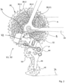
- the rear derailleur 32 comprises a fixed element 42, which is also referred to as a "B-knuckle” and which has a fastening section 43 for fastening to the frame 16, preferably using a derailleur hanger. Furthermore, the rear derailleur 32 includes a movable element 44, which is also referred to as a "P-knuckle” and carries a chain guide arrangement 46 with a lower chain guide wheel 48 and an upper chain guide wheel 50 in a manner known per se.
- the chain guide assembly 46 is rotatably supported on the movable member 44 about an axis B parallel to the axis A and is biased in the rearward direction, ie, in figure 2 clockwise, preloaded to keep the chain 34 taut and in particular to compensate for the different chain travels around the different sized sprockets 30-1...30-11.
- Movable member 44 is movably coupled to fixed member 42 by a hinge assembly 52 .
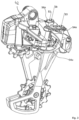
- the hinge assembly 52 is particularly in the Figures 3 to 5 easy to recognize and can be designed as in the exemplary embodiment of the parallelogram type.
- Such a joint arrangement 52 comprises at least one outer pivoting element, here an upper outer pivoting element 54o and a lower outer pivoting element 54u, and at least one inner pivoting element, here an upper inner pivoting element 56o and a lower inner pivoting element 56u.
- First ends of the upper and lower outer pivot members 54o, 54u are pivoted to the fixed member 42 at a first pivot axis S1.
- First ends of the upper and lower inner pivot members 56o, 56u are pivoted to the fixed member 42 at a second pivot axis S2 spaced from the first pivot axis. Second ends of the upper and lower outer pivot members 54o, 54u, opposite to the first ends, are pivoted to the movable member 44 at a third pivot axis S3. Second ends of the upper and lower inner pivot members 56o, 56u, opposite the first ends, are pivotally supported on the movable member 44 at a fourth pivot axis S4 spaced apart from the third pivot axis S3.
- pivot axes S1, S2, S3 and S4 essentially form the corner points of an articulated parallelogram and in this way allow a movement of the movable element 44 and thus the chain guide arrangement 46 in the axial direction (parallel to the main axis A) outwards and inwards, respectively to guide the chain 34 from one of the sprockets 30-1...30-11 to another sprocket.
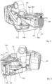
- the movable element 44 is moved by an electromechanical drive 58 (see also figure 6 ) having a motor-gearbox assembly housed in a housing 60 and providing power to move the moveable member at an output member movably coupled to the linkage assembly 52 or the moveable member 44.
- the output member is formed by a drive arm 62 which has a stop 64 which is mounted on a counter-stop 66 (see FIG figure 5 , drive arm 62 omitted here for illustration) of the lower inner pivot member 56u so as to be able to pivot the lower inner pivot member 56u in an outward direction, thereby causing the movable member 44 to move outwardly.
- the drive arm 62 is held in abutting contact with the lower inner pivoting member 56u under the tension of a spring 68, the spring 68 bearing on the one hand in a housing 70 on the drive arm 62 and on the other hand on the movable member 44.
- spring 68 may be supported on fourth pivot axis S4 and configured to bias movable member 44 in an inward direction.
- the electromechanical drive 58 is operated in such a way that the drive arm 62 moves in an outward direction, over the stop 64 and the counter stop 66 takes the lower inner pivoting element 56u directly with it.
- the electromechanical drive 58 is operated such that the drive arm 62 moves in an inward direction. The force of the spring 68 causes the joint arrangement 52 to follow this movement of the drive arm 62, i.e.
- the spring 68 keeps the counter-stop 66 of the lower inner pivoting element 56u in contact with the stop 64 of the drive arm 62.
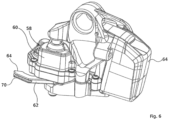
- FIG 7 shows that the gear housing 60 of the electromechanical drive 58 is formed in the illustrated exemplary embodiment from an upper gear housing part 60o and a lower gear housing part 60u, which are fastened to one another by suitable connecting means, here screw connections 63, and in their interior a cavity for receiving the later define descriptive motor-transmission arrangement.
- the gear housing 60 can in turn be accommodated between two housing parts of the fixed element, for example between an upper housing part 42o on which also the attachment portion 43 is arranged to be attached to the frame 16, and a lower case 42u.
- the upper housing part 42o and the lower housing part 42u can be screwed together in order to fix the transmission housing 60 securely and without play in a precisely predetermined position.
- Power to operate the electromechanical drive 58 is provided by a removable battery 64 in the illustrated embodiment.
- the battery 64 and the transmission housing 60 can be coupled to one another or separated from one another both mechanically and electrically.
- Mechanical connection means can be formed, for example, by a hook 66 which engages in a matching recess 68 of the battery, or vice versa.
- Electrical connection means can be implemented by suitable pins 70 and matching recesses 72.
- the electromechanical actuator 58 may be powered by a remote power source connected to the actuator 58 by an electrical cable.
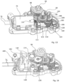
- FIG 13 shows an internal structure of the electromechanical drive 58, in particular a motor-gear assembly, wherein in figure 13 some parts are hidden for better illustration.
- the motor-gear assembly includes, in particular, a motor 74 with electrical connections 76 for applying a motor voltage and a motor output shaft 78.
- the rapid rotation of the electric motor 74 is converted by a gear 80 into a slow rotation of a gear output shaft 82, which drives the drive arm 62 and can be held in particular non-rotatably with the drive arm.
- a motor carrier is provided in the form of a carrier plate 84, which is to be fastened to the lower transmission housing part 60u in a first step.
- the carrier plate 84 is preferably formed from a metal and therefore has high mechanical strength.
- the gear case 60 is formed of a lighter weight material, particularly plastic.
- the support plate 84 is at least partially embedded in the plastic material of the lower gear housing part 60u for secure mounting on the lower gear housing part 60u. Embedding of the support plate 84 can take place during the production of the lower gear housing part 60u, for example during an injection molding process, or subsequently after the hardening of the lower gear housing part 60u.
- the support plate 84 preferably has at least one projection 86 which is embedded in the plastic material of the lower transmission housing part 60u.
- At least one through opening or recess 88 can also be provided in the at least one projection 86, into which plastic material can at least partially penetrate.
- adhesives can be used and the support plate 84 can be glued with its at least one projection 86 in a corresponding recess of the lower transmission housing part 60u.
- a mounting section 90 of the support plate 84 remains free in the installed state and is accessible for mounting the motor 74 .
- the mounting section 90 has second fastening means 92 for fastening the motor 74 to the carrier plate 84 .
- the second fastening means 92 are implemented as holes, to which the motor 74 can be attached with screws 94 can be screwed on.
- the assembly section 90 is preferably plate-shaped and, in the assembled state, lies flat against a plate-shaped section of the motor 74, for example an end face of the motor 74 from which the motor output shaft 78 also emerges. In this way a reliable, stable and very precise positioning of the motor and in particular the motor output shaft 78 is achieved.
- the motor 74 can be assembled by the second fastening means 92 in a relatively simple assembly process.
- first gear wheel 96 Fixedly connected to the transmission output shaft 78 is a first gear wheel 96 which, for reasons of space, is designed as a segmented wheel, so that it is only toothed over its operating angle and is recessed in other peripheral sections.
- the first gear wheel 96 meshes with a small wheel 98 of a first step wheel 100.
- Non-rotatably connected to the small wheel 98 of the first step wheel 100 is a large wheel 102 of the first step wheel 100, which in turn meshes with a small wheel 104 of a second Step wheel 106.
- a large wheel 108 of the second step wheel 106 is designed as a worm wheel and is in engagement with a worm 110 which is arranged on a worm shaft 112 in a rotationally fixed manner.
- the axes of rotation of the first gear wheel 96, the first step wheel 100 and the second step wheel 106 are preferably aligned parallel to one another, while the worm shaft 112 preferably runs at an angle of 90° to the axis of rotation of the second step wheel 106.
- the worm shaft 112 also carries a third gear wheel 114 which in turn meshes with a fourth gear wheel 116 which is arranged on the motor output shaft 78 in a rotationally fixed manner.
- the third gear 114 is preferably larger than the fourth gear 116.
- the rapid rotation of the transmission output shaft 78 via the fourth gear 116, the third gear 114, the worm shaft 112, the worm 110, the large gear 108 of the second stage gear 106, the small gear 104 of the second stage gear 106 , the large gear 102 of the first stage gear 100, the small gear 98 of the first stage gear 100 and the gear wheel 96 are converted into a slower rotation of the transmission output shaft 82.
- the design of the transmission 80 is to be understood as an example; alternatively, transmissions with more or fewer gear stages or with other reduction mechanisms can be used, provided they are suitable for sufficiently adapting the speed of the motor 74 to the desired speed of the transmission output shaft 82 .
- the transmission 80 may further include an overload clutch 118 which may be located at any suitable position in the power path from the engine output shaft 78 to the transmission output shaft 82 as described above.
- an overload clutch 118 which may be located at any suitable position in the power path from the engine output shaft 78 to the transmission output shaft 82 as described above.
- the small and large wheels of the stepped wheels which are normally non-rotatably connected to one another for torque transmission, can be mounted rotatably on one of the stepped wheels in relation to one another. In the present exemplary embodiment, this is implemented with the second step wheel 106 and the overload clutch 118 is arranged between the small wheel 104 and the large wheel 108 of the second step wheel 106 .
- the overload clutch 118 can be embodied, for example, as a slipping clutch and can have a first clutch plate 120, which is fixedly connected to the small wheel 104 of the second step wheel 106, and a second clutch plate 122, which is fixedly connected to the large wheel 108 of the second step wheel 106 is.
- the first clutch plate and the second clutch plate frictionally engage each other so that they transmit rotational force when a differential torque acting between the first clutch plate 120 and the second clutch plate 122 is less than a predetermined overload torque, and rotate relative to each other when the differential torque is greater than the predetermined overload torque.
- the overload torque is preferably adjustable.
- the overload clutch 118 can alternatively or additionally be provided on the first step wheel 100 instead of on the second step wheel 106 .
- the transmission 80 may further include a position sensing mechanism 124 that senses a current position or rotational position of the transmission 80 .
- the position detection mechanism 124 detects a rotational position of the first gear wheel 96.
- the position detection mechanism 124 can have a second gear wheel 126, which is also in mesh with the first gear wheel 96 and, on the other hand, is in turn in mesh with a fifth gear wheel 128, which has a position sensor 130 wears.
- the axes of rotation of the second gear wheel 126 and the fifth gear wheel 128 are in turn parallel to the axis of rotation of the transmission output shaft 82.
- the position sensor 130 can be an encoder known per se, which interacts magnetically or optically with a reading head (not shown) held in place in the housing in order to detect the rotational position of the fifth gear wheel 128, in particular without contact. Accordingly, it is important that the rotational position of the fifth gear wheel 128 can be assigned as precisely as possible to a specific rotational position of the first gear wheel 96 . Hence the requirement to reduce any backlash in the transmission path from the fifth gear 128 to the first gear 96 . According to one aspect of the invention, an anti-game mechanism is used for this purpose, which is described below with reference to FIG Figures 15 and 16 is explained in more detail.
- the anti-backlash mechanism is realized by the second gear wheel 126, which comprises two partial wheels 132, 134 held coaxially to one another.
- the two partial wheels, an upper partial wheel 132 and a lower sub-wheel 134 have the same number of teeth and are both simultaneously engaged with both the first gear wheel 96 and the fifth gear wheel 128.
- the sub-wheels 132, 134 are rotatable relative to one another about the axis of rotation of the second gear wheel 126.
- the relative rotation of the partial wheels 132, 134 is preloaded by a force which is generated by an anti-backlash spring 136 in the present exemplary embodiment.
- the anti-backlash spring 136 is preferably a torsion spring and has one end 138 engaging the upper partial gear 132 and an opposite end (not shown) engaging the lower partial gear 134 .
- the largest part of the anti-backlash spring 136 is preferably accommodated in a space-saving manner in a cavity 140 which is formed between the upper partial wheel 132 and the lower partial wheel 134 .
- the upper part-wheel 132 can have a first recess 142 facing the lower part-wheel 134, which can be designed as a circular or ring-shaped indentation.
- the lower partial wheel 134 can have a second recess 144 which faces the upper partial wheel 132 and which can be designed as a circular and annular depression.
- the engagement of the end 138 of the spring 136 with the upper part gear 132 may be accomplished by inserting the end 138 into an opening 146 of the upper part gear 132 .
- the other end (not shown) of the anti-backlash spring 136 can be maintained in engagement with the lower split gear 134 .
- the flanks of the partial gears 132, 134 lie closely against the flanks of the teeth of the first gear wheel 96 and of the fifth gear 128 so that backlash between the gears is reduced.
- the anti-backlash mechanism of this embodiment can reduce the backlash between the first gear 96 and the fifth gear 128 even further.
- the lower part-wheel 134 is held on a gear shaft 146 of the second gear wheel 126 with less play than the upper part-wheel 132.
- the lower part-wheel 134 can be held on the gear shaft 146 in a rotationally fixed manner or essentially without play so that it can rotate, while the upper partial wheel 132 is mounted with a predetermined clearance d to the transmission shaft 146.
- the transmission shaft 146 could have a larger diameter in the upper axial section than in the lower axial section, so that instead of the upper partial wheel 132 the lower partial wheel 134 then has radial play on the transmission shaft 146 .
- the diameter of an upper central receiving opening 148 in upper partial gear 132, in which gear shaft 146 is received could be larger than a diameter of a lower central receiving opening 150 in lower partial gear 134, in which lower partial gear 134 is attached to the gear shaft 146 is stored.
- the diameter ratios of the central openings 148, 150 can also be reversed here, so that instead of the upper partial wheel 132, the lower partial wheel 134 then has radial play on the transmission shaft 146.
- the result of a play d of the type described above is a predetermined radial play of the upper partial gear 132 relative to the transmission shaft 146 and thus also relative to the lower partial gear 134.
- the radial movement can also be biased by the force of the anti-backlash spring 136, so that the anti-backlash spring 136 has a dual function. Due to the additional radial play d, an even better fit between the upper partial gear 132 and the first gear wheel 96 and the fifth gear wheel 128 can be achieved, so that there is an additional reduction in play. It should be noted, however, that it was found that even without the additional feature of radial play in one of the two partial wheels 132, 134, a very good and significant reduction in play can already be achieved by the relative rotation of the two partial wheels 132, 134.
- figure 17 12 shows the structure of the first step wheel 100.
- the small wheel 98 and the large wheel 102 can each be formed separately from a transmission shaft 152, which forms the axis of rotation of the first step wheel 100.
- the small wheel 98 has a through opening 154 through which the transmission shaft 152 is passed
- the large wheel 102 has a through opening 156 through which the transmission shaft 152 is also passed.
- the small wheel 98 and the large wheel 102 are held against rotation with one another and can be manufactured as separate components and fastened together or can be formed in one piece as an integral structure.
- Small gear 98 and large gear 102 are preferably rotatably supported on gear shaft 152 so that gear shaft 152 can be secured within the housing.
- small gear 98 and the large gear 102 can be made of a material which is different from the material of the transmission shaft 152.
- small gear 98 and large gear 102 can be made of hardened steel in order to transmit large torques and to reduce the wear of the teeth of the wheels, while the gear shaft 152 can be formed of a non-hardened steel to avoid hardening distortion of the gear shaft 152 to counteract.
- the regarding figure 17 The features described above can be implemented alternatively or additionally on the second step wheel 106 or on another step wheel of the transmission 80 .
- rotary power of the motor 74 is translated via the transmission 80 and linkage assembly 52 into movement of the movable member 44 to shift the derailleur 32 to set the desired gear ratio.
- the motor 74 is controlled by an electronic control device 160, which is shown schematically in figure 14 can be seen.
- the electronic control device 160 communicates with the electrical connections 76 (although in figure 14 (e.g., electrical connections 76 are shown disconnected and leading away from electronic controller 160 for purposes of illustration) to apply a motor voltage U to motor 74.
- the electric motor 74 can be operated in a manner known per se, for example via PWM control (pulse width modulation control).
- the electronic control device 160 is also supplied with electrical energy from the battery 64 via the contacts 70 , 72 .
- the electronic control device 160 has receiving means 162 in order to receive control commands from the operating element 36 or from another device.
- signal transmission means known per se can be used here, for example a connection using an electrical cable or, preferably, wireless data transmission.
- the receiving means 162 can include a radio receiver which is set up to receive radio signals from a radio transmitter of the operating element 36 .
- one of the US 2014/0102237 A1 known wireless control are used.
- FIG 18 shows as a schematic block diagram an example of an electronic control device 160 of the type described above, which is implemented on a circuit board 164 and electrically connected to the Motor 74, the battery 64 and the position sensor 130 is connected.
- the circuit board 164 is preferably housed in the transmission housing 60 as well.
- a CPU 166 and a memory 168 connected to the CPU 166 are preferably installed on the circuit board 164 .
- the circuit board 164 can also carry a radio module 170, which forms receiving means 162 of the type described above.
- the circuit board 164 can carry an acceleration sensor 172 which can detect a vibration or movement of the rear derailleur 32 and forward a corresponding signal to the CPU 166 .
- a function switch 174 may be mounted on the circuit board 164 for switching the electronic controller 160 between different modes of operation, resetting, turning it on or off, or the like.
- a display element for example in the form of an LED 176, can be installed on the circuit board 164 and connected to the CPU 166 in order to optically signal operating states of the electronic control device 160.
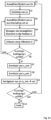
- a method for controlling the actuating device 10 is explained in more detail below.
- the method can be implemented in particular by a program running in the CPU 166 .
- the radio module 170 receives a switching stage selection signal, for example the switching signal from a driver for setting the rear derailleur in a specific switching stage Sn, selected from the number of available switching stages (eleven switching stages in the exemplary embodiment).
- the electronic control device 160 determines a shift position sn assigned to the shift stage Sn.
- the CPU 166 can read out a shift table stored in the memory 168, which contains an assigned shift position for each available shift stage.
- step S3 the motor 74 is operated with a motor voltage U1 and then the actuating device 10 detects the position s of the movable element 44 in step S4.
- the position s can be determined from an output of the position sensor 130, which indicates the angular position of the first Gear wheel 96 represents. If it is determined in step S5 that the position s of the movable element has reached the switching position sn of the desired switching stage Sn, the switching process is completed in step S21. This corresponds to the case that the switching process could be carried out successfully.
- step S6 it is checked whether the transmission is rotating, which is preferably also done by querying the position sensor 130, e.g. by querying a change over time in the Output of the position sensor 130 can take place. If the transmission does not turn (although the shift position sn has not yet been reached), the method concludes that there is a fault (step S7), caused, for example, by the blocking of the movable element 44, by excessive wear or the like. If, on the other hand, the transmission is still rotating (S6 YES), the method returns to step S4. Steps S4 to S6 thus form a waiting loop for fault detection, in which the position s of the movable element is repeatedly queried and it is determined whether the movable element will eventually reach the desired switching position or whether a fault will occur.
- step S9 the method again detects the position s of the movable element 44 and then checks in step S10 whether the switching position sn has been reached in the meantime or not. If the switching position sn has been reached, the method ends in step S21. Wasn't the switch position yet reached, it is checked again in step S11 whether the transmission is now turning. If the transmission is still stationary (S11 NO), in step S13 it is checked whether the time tz1 measured by the first timer has already exceeded a predetermined first time period ⁇ T1 or not.
- step S9 If the first period of time ⁇ T1 has not yet been exceeded, the method returns to step S9, ie again detects the position s of the movable element 44 and queries a rotation of the transmission, the motor continuing to be operated with the motor voltage U1. Should the transmission move again in the meantime (S11 YES), the timer tz1 is reset to zero in step S12, since the method now assumes that the fault has been rectified and after some time the shift position sn will be reached (S10 YES).
- step S13 If, on the other hand, it is determined in step S13 that the first time period ⁇ T1 has been exceeded, i.e. the shifting process could not be successfully completed even after a time ⁇ T1 has elapsed after the fault was detected (S 13 YES), then in a following step S14 the engine is second motor voltage U2 operated, which is lower than the first motor voltage U1.
- the motor voltages U1 and U2 are adapted to a limit voltage Uc of the overload clutch 118.
- the limit voltage Uc of the overload clutch is the voltage with which the electric motor 74 is to be operated in order to keep the overload clutch 118 straight in the event that the transmission output shaft 82 is blocked trigger.
- step S15 proceeds to step S15 and starts a second timer tz2, ie sets it to 0.
- the first and second timers only represent operands and can be controlled by a common clock or by themselves can only result from subtractions of a continuous clock generator.
- step S16 the position s of the movable element 44 is again detected, whereupon it is checked in step S17 whether the position s of the movable element 44 has reached the switching position sn or not. If the desired switching position has now been reached, the switching process is successfully completed (S21). If the desired shift position sn has not been reached, then in step S18 the method again requests rotation of the transmission. If the transmission is stationary (S18 NO), the method checks in step S20 whether or not the second timer tz2 indicates that a second time period ⁇ T2 has been exceeded.
- step S16 the method returns to step S16 so that the motor continues to be operated with the motor voltage U2 and the position detection and query of the gear rotation are repeated. If it is determined in the meantime that the transmission is turning again (S18 YES), the second timer is reset to zero in a step S19, since it is assumed that the fault has been rectified and the movable element continues to move in the direction of the shift position.
- the method determines that the shifting process has failed and carries out error handling in step S22.
- the error handling can include the output of an error message in the form of an optical or acoustic signal, the transmission of an error message by the radio module 170 or the like. If necessary, after waiting for a further third period of time .DELTA.T3, the method can attempt a new shift, ie return to step S3. Alternatively, the method can wait until another switching signal is sent by the user.
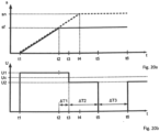
- Figures 20a and 20b show the effect of the switching method described above using two timing diagrams, the two time axes t of Figures 20a and 20b have the same standards, so that Figures 20a and 20b can be compared with each other in relation to the time axis t.
- a normal, trouble-free switching process is represented by a dashed line.
- the movable member 44 moves to the shift position sn corresponding to the desired shift stage and reaches it at a time t4.
- a solid line on the other hand, that is in Figure 20a illustrates the case of a fault in which the movement of the movable element 44 is impeded, for example, by external mechanical influences, wear or dirt.
- the movable element then does not reach the desired switching position sn, but remains at a time t2 at a switching position sf, which is different from sn.
- This disturbance at time t2 can be detected, for example, by the output of the position sensing element 130 indicating that the position of the movable element 44 is no longer changing or is no longer changing in the expected manner.
- the motor voltage U1 at the motor 74 is then maintained for a period of time ⁇ T1.
- the motor 74 is therefore still supplied with full power for the time period ⁇ T1, which can also lead to the overload clutch 118 being triggered if the disturbance persists.
- the motor voltage is reduced to the reduced motor voltage U2 at the time t3, so that the overload clutch 118 remains coupled or is coupled again in any case.
- the motor 74 is then operated with the reduced motor voltage U2 for the period of time ⁇ T2 in order to continue trying to reach the desired switching position sn, in which case, however, a triggering of the overload clutch 118 is avoided.
- the motor voltage is preferably reset to 0 at a time t5, so that the motor 74 is preferably turned off.
- a new shift attempt can then be made, for example, at a point in time t6 when the operator issues a new shift command or a predetermined period of time ⁇ T3 has expired.
- the first period ⁇ T1 can be between 5 ms and 80 ms, preferably between 10 ms and 40 ms, in order to reduce repeated triggering of the overload clutch.
- the second time period ⁇ T2 is preferably longer than the first time period ⁇ T1 and can be between 40 ms and 500 ms, preferably between 60 ms and 200 ms, in order to wait long enough for the fault to be rectified, but at the same time to keep the load on the circuit low .
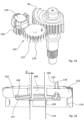
- figure 21 shows schematically the course of the chain 34 between the front chain ring 26, the rear derailleur 32 and the rear sprocket set 30. For reasons of clarity, only five sprockets 30-1 to 30-5 are shown.
- the movable element 44 of the rear derailleur 32 in particular the chain guide wheels 50, move the chain to a position s, so that the chain is ideally aligned with a predetermined sprocket of the sprocket pack or is in any case in an ideal position for smooth chain travel with respect to the pinion is located.
- the rear derailleur 32 moves the chain 34 via the respective sprockets 30-1, 30-2, ...
- Each shift stage is thus a shift position s1, s2, ... assigned.
- This assignment can be in the form of switch position parameters in a switch table ( figure 22 ) be stored, the switch position parameters can be the switch positions themselves or the switch positions can be specifying parameters.
- the shift table may be stored in memory 168 of electronic controller 160 .
- the electronic control device 160 determines an associated value sn from the shifting table in order to set a desired shift stage Sn and controls the motor 74 in such a way that the movable element 44 reaches the shifting position sn.
- the shifting position sn is not directly stored in the shifting table of the present exemplary embodiment. Instead, a standard position (standard position parameter) s0_1, s0_2, ... and a trim amount (trim parameter) x1, x2, ... are stored in the switching table for each switching step.
- the switching position sn then results from the sum of the standard position s0 and the amount of trimming x.
- the switching position s1 of switching stage 1 results from the sum s0_1 + x1 etc. This allows the switching position to be easily reset to a basic setting or factory setting.
- the entries in the shift table can be changed in such a way that two shift position parameters of different shift stages are changed by different amounts.
- a switching table based on the model of figure 22
- the changes in the entries in the switching table can preferably be implemented by control commands received wirelessly, in particular by control commands which are received by the radio module 170 and forwarded to the CPU 166 and the memory 168 .
- a wireless input device in particular a mobile terminal device, can be used for this. Particularly preferred is the use of a smartphone, tablet or similar mobile device on which a predetermined program code (app) is installed, which gives the user the opportunity to directly influence the switching table.
- such a program code can prompt the user to enter a desired switching stage and to enter a trimming amount for this switching stage.
- the program code can also be set up to issue an instruction to the electronic control device 160 to set a specific switching stage.
- the radio module 170 can be set up to transmit data about stored entries in the switching table to the mobile terminal device.
- the program code can give a user the option of gradually increasing or decreasing the trimming amount x for a selected switching stage, with the program code sending an instruction to the electronic control device 160 for each trimming amount set, to move the movable element to the corresponding switching position to be adjusted, which results from the standard position and the trimming amount.
- This enables the user to trim the shifting position of a specific shifting step during operation, that is to say to check the smooth running of the chain and the exact alignment between the chain guide wheel 50 and the sprocket 30-n at the same time.
- the user can then set each of the switching stages, check the switching process or the chain run and the alignment between chain guide wheel 50 and pinion 30-n and, if necessary, make an exact adjustment of the switching position individually for each switching stage.
- checking the chain run and the optimal shifting position can be supported by evaluating the output of acceleration sensor 172.
- acceleration sensor 172 can detect a vibration and send a value representing the strength or amplitude of the vibration to CPU 166 to transfer.
- the CPU 166 can display the value representing the vibration to the user in a suitable form, for example by transmitting the value via the radio module 170 to a receiving unit, in particular a mobile terminal device, on which the the value representing the vibration is displayed, or by appropriate activation of the LED 176, which, in a simple variant, could output information about the strength or amplitude of the vibration by means of a specific flashing code or the like.
- the user can then advantageously use a method for trimming the actuating device, in which he sets a specific switching stage S1 and then sets different trimming amounts x, so that the movable element 44 is moved into switching positions that are in the vicinity of the previously entered switching position, in particular are in the standard switching position S0.
- the user can record the magnitude of the vibration, whereupon he can finally select that trim amount or shift position at which the vibrations were lowest.
- Such a setting corresponds with a good approximation to an optimal switching position.
- the user can finally repeat the process for each switching stage for which he wants the switching position to be adjusted.
- a trimming process for one or more gear stages can be carried out semi-automatically or fully automatically using an in figure 23 illustrated trimming program.
- the trimming program can either run directly on the CPU 166 or alternatively on a control device connected to the electronic control device 160 .
- the trimming program can be installed on a mobile terminal device, such as a smartphone, and can transmit the individual control instructions wirelessly to the CPU 166 via the radio module 170 .
- a switching stage Sn is selected or a switching stage that has already been set is changed.
- the subsequent step S2 based on the switching table ( figure 22 ) determines the switching position sn assigned to the switching stage Sn (for example by adding the standard switching position s0_n to the trim amount xn).
- a value si is selected from an interval ⁇ s, which encloses the shift position sn (sn lies in the interval ⁇ s).
- the interval ⁇ s is preferably less than or equal to an average distance between the shift positions of two adjacent shift stages.
- Steps S3 to S5 are preferably repeated until a predetermined exit determination 1 is met.
- a different value si is selected from the interval ⁇ s, the movable element is moved to the new position si and the vibration vi is measured. This cycle is repeated until exit condition 1 is met.
- exit condition 1 it can be provided that a predetermined number of different positions si have been approached and tested.
- the positions si can be chosen at regular intervals from a smallest value of the interval ⁇ s to a largest value of the interval ⁇ s and the exit condition 1 is met when all positions si have been approached.
- exceeding a predetermined period of time or a user input can be selected as exit condition 1.
- step S7 if the exit condition 1 is met, the vibrations vi measured for the respective position si are compared with one another and a minimum value v_min is determined.
- the position si, at which the minimum value v_min is assumed, is determined in step S8 as the position with the lowest vibration s_min.
- step S9 updates the corresponding shift position parameter in the shift table so that the shift table now results in the value x_min as the new shift position sn for this shift stage Sn (for example, the trim amount xn is set to x_min-s0_n).
- the switching table is therefore updated and rewritten for this switching stage Sn.
- Steps S1 to S9 can be executed repeatedly for a plurality of shift stages Sn until an exit condition 2 is met.
- exit condition 2 can require that all shift stages of the rear derailleur 32 have been selected at least once (step S1) and thus an optimal shift position parameter has been determined for all shift stages by steps S2 to S9.
- the exit condition 2 can request the expiration of a predetermined period of time or request a user input. If exit condition 2 is met, the trimming program ends (step S11).
- FIG. 12 shows a variant of the trimming program described above according to the invention.
- the trimming program is started, for example by user input via the function switch 174 or by a start command which was entered on the mobile terminal and received by the radio module 170 of the electronic control device 160 .
- a position si within the maximum movement range of the movable element 44 from s_min to s_max is then selected in step S'2.
- the electromechanical drive 58 then moves the movable element 44 to the position si in step S'3, whereupon in step S'4 a vibration vi is detected at this position si.
- Steps S'2 to S'4 are executed in the cycle until an exit condition of step S'5 is met.
- the movable element completely runs through the entire range of movement from s_min to s_max once and preferably also runs through the range of movement again in the opposite direction, if necessary the range of movement even more than twice runs through completely, ie sets all possible positions s of the movable element at least once. Accordingly, the exit condition of step S'5 queries whether the entire range of movement of the movable element has been completely traversed the desired number of times.
- the vibrations vi measured at this position si can advantageously be averaged in order to determine a mean vibration vim for each position si, so that the accuracy of the vibration measurement is improved.
- step S'6 the program searches in step S'6 in the data series of the measured values of the vibration vi or vim for minimum values v_min1, v_min2, ... and determines these in step S'7 Positions s_min1, s_min2, . Accordingly, in step S'8, a shift table is updated in such a way that the stored shift positions s1, s2, . . . are replaced by the newly found best shift positions s_min1, s_min2, .
- variants of the trimming device or the trimming method and the trimming program mentioned above allow individual adjustment of individual trimming amounts or individual switching positions of the respective switching stages.
- variants of the invention are also considered to be advantageous in which a single trimming process affects the trim amounts of all switching stages or essentially all switching stages at the same time, albeit to a different extent.
- a particularly simple trimming function is achieved in order to compensate for misalignments between the rear derailleur 32 and the sprocket set 30, which continuously increase or decrease from sprocket to sprocket.
- An example of this is an adjustment in the position of the movable element 44 as a result of an axial force exerted by the chain 34 .
- this tensile force increases, with the extent of the associated misalignment between rear derailleur 32 and sprocket set 30 also increasing with increasing offset between sprocket and front chainring 24, i.e. with increasing inclination of chain 34.
- the electronic controller 160 can then be set up to change the trimming amounts x1, x2, .
- the adjusting device can advantageously be set up to allow the trim amounts to increase as the distance between the shift positions and the shift position sn increases.
- a trimming process with such predefined sets of trimming amounts can be carried out in the in figure 24 follow the illustrated sequence of steps.
- This in figure 25 The trimming procedure illustrated can be carried out, for example, after the initial installation of a rear derailleur on a bicycle, during maintenance work or after replacing components of the bicycle.
- a neutral gear stage SN is a specific shift stage, usually a middle shift stage, in which there is essentially no chain oblique position, i.e. a pinion which is arranged at approximately the same axial height as the chainring.
- step S101 it is checked in step S101 whether the shift position set by the rear derailleur is correct, i.e. whether the chain guide wheel is set at the correct axial height relative to the corresponding sprocket.
- the synchronization of the chain can be checked or a vibration of the rear derailleur can be detected, as described above.
- a trimming procedure 1 (step S102) is carried out, which can essentially correspond to a trimming process known per se, for example a trimming process in which all shift positions are changed by essentially the same amount.
- the trimming procedure 1 is completed when the correct shift position for the neutral shift stage SN is reached.
- step S103 the rear derailleur is set to an extreme shift stage, for example the highest shift stage or the lowest shift stage (step S103).
- step S104 it is checked again whether the switching position of the movable element is correct, ie whether the chain guide wheel is in the correct position relative to the sprocket. If this is not the case (step S104 NO), a trimming procedure 2 is initiated, which works with different trimming amounts for the different shift positions.
- a set of trimming amounts can be selected in which the trim amounts are adjusted simultaneously, but by different amounts.
- a number of predefined sets of trim amounts are available, which can be optionally adjusted.
- the adjustment process can be carried out by a user manually or by an electronic command to change the shift table. Once a suitable amount of trim has been found that will ensure correct positioning in the selected gear ratio, the trimming process finally ends in step S106. If desired, the method S100 to S106 can be repeated for different shift stages, in particular different extreme shift stages, in order to find the appropriate trim amounts.
Abstract
Verfahren zur Steuerung von Stelleinrichtungen für Fahrräder sowie Verfahren zur Einstellung solcher Stelleinrichtungen und Stelleinrichtungen für ein Fahrrad, umfassend: ein feststehendes Element (42), welches in Bezug auf einen Fahrradrahmen (16) ortsfest angeordnet ist, ein bewegliches Element (44), welches in Bezug auf das feststehende Element (42) beweglich ist, einen elektromechanischen Antrieb, welcher Antriebskraft für eine Bewegung des beweglichen Elements (44) bereitstellt.Method for controlling actuators for bicycles and method for adjusting such actuators and actuators for a bicycle, comprising: a fixed element (42) which is arranged in a stationary manner in relation to a bicycle frame (16), a movable element (44) which is Movable with respect to the fixed member (42), an electromechanical actuator providing motive power for movement of the movable member (44).
Description
Die vorliegende Erfindung betrifft Stelleinrichtungen für Fahrräder, Verfahren zur Steuerung von Stelleinrichtungen für Fahrräder sowie Verfahren zur Einstellung solcher Stelleinrichtungen.The present invention relates to adjusting devices for bicycles, methods for controlling adjusting devices for bicycles and methods for adjusting such adjusting devices.
Eine elektromechanische Stelleinrichtung für ein Fahrrad in Form eines elektrischen Schaltwerks ist beispielsweise aus der
Nachteilig an dieser Konstruktion ist, dass die Kraft der Torsionsfeder von der Drehstellung des Spannrads abhängt und die für einen optimalen Betrieb ausgelegte Spannkraft nur bei einem bestimmten Drehwinkel oder über einen kleinen Drehwinkelbereich hinweg wirkt. Am Anfang und am Ende des Drehwinkelbereichs ist dagegen die Spannkraft der Torsionsfeder entweder zu gering, so dass die Spielreduzierung nicht mehr zuverlässig gewährleistet ist, oder ist zu hoch, so dass die Torsionsfeder das Ausgangsdrehmoment des Getriebes zu stark beeinflusst.The disadvantage of this design is that the force of the torsion spring depends on the rotary position of the tensioning wheel and the tensioning force designed for optimal operation only acts at a specific angle of rotation or over a small range of angles of rotation. On the other hand, at the beginning and at the end of the rotation angle range, the clamping force of the torsion spring is either too low, so that the backlash reduction is no longer reliably guaranteed, or is too high, so that the torsion spring influences the output torque of the transmission too much.
Eine weitere Herausforderung bei der Konstruktion elektromechanischer Stelleinrichtungen für Fahrräder liegt in der Auslegung und Positionierung der Getriebeelemente, insbesondere der darin verbauten Stufenzahnräder. Bei den bekannten Lösungen ist zumindest ein kleineres der beiden Zahnräder des Stufenzahnrads, auch "Ritzel" genannt, einteilig mit der Getriebewelle ausgebildet. Um steigenden Ansprüchen an die zu übertragenden Drehmomente gerecht zu werden, besteht nun der Wunsch, gehärtete Zahnradstufen zu verwenden. Hierbei tritt jedoch die Problematik auf, dass eine Härtung des Ritzels zusammen mit seiner Getriebeachse insbesondere bei längeren Achsen zu einem Härteverzug führt und die Positioniergenauigkeit der Getriebewellen beeinträchtigt wird. Außerdem stellen bisherige Stufenzahnräder relativ hohe Anforderungen an die Position der Lagerung der Getriebeachsen in den zugeordneten Drehlagern.Another challenge in the construction of electromechanical actuating devices for bicycles lies in the design and positioning of the transmission elements, in particular the stepped gears installed in them. In the known solutions, at least one smaller of the two gears of the step gear, also called the "pinion", is formed in one piece with the transmission shaft. In order to meet increasing demands on the torques to be transmitted, there is now a desire to use hardened gear stages. Here, however, the problem arises that hardening of the pinion together with its gear axle leads to a hardening distortion, particularly in the case of longer axles, and the positioning accuracy of the gear shafts is impaired. In addition, previous step gears make relatively high demands on the position of the bearing of the transmission axles in the associated pivot bearings.
Die Montage von herkömmlichen Getrieben für elektromechanische Stelleinrichtungen für Fahrräder wird ferner dadurch erschwert, dass die Position der Ausgangswelle des Motors sehr genau auf die Position des Eingangselements des Getriebes abgestimmt sein muss. Dies kann insbesondere dann problematisch sein, wenn entsprechend der ständigen Forderung einer Reduzierung von Gewicht von Fahrradkomponenten als Material für das Gehäuse ein Kunststoffmaterial eingesetzt wird, da Schraubverbindungen zur Befestigung von Motor oder Getriebebauteilen am Gehäuseteil die Gefahr bergen, dass die exakte Position der Elemente von der Anzugskraft der Schrauben abhängt. Solche Schraubverbindungen zwischen Metall und Kunststoff neigen darüber hinaus dazu, sich mit der Zeit zu verziehen oder zu lockern.The assembly of conventional transmissions for electromechanical actuators for bicycles is further complicated by the fact that the position of the output shaft of the motor has to be very precisely matched to the position of the input element of the transmission. This can be particularly problematic when, in accordance with the constant requirement to reduce the weight of bicycle components, a plastic material is used as the material for the housing, since screw connections for fastening motor or transmission components to the housing part harbor the risk that the exact position of the elements of depends on the tightening force of the screws. Such screw connections between metal and plastic also tend to warp or loosen over time.
Eine weitere elektromechanische Stelleinrichtung ist aus der
Es hat sich in der Praxis gezeigt, dass für den zufriedenstellenden Betrieb einer solchen elektromechanischen Stelleinrichtung eine recht genaue Abstimmung zwischen dem maximalen Motorstrom, dem Überlastdrehmoment und dem Zeitpunkt der Abschaltung des Motorstroms erfolgen muss, um die gewünschte Wirkung einer Vermeidung von Beschädigungen zu erreichen. Ist das Überlastdrehmoment zu hoch eingestellt, so kommt es im Falle einer Blockierung des beweglichen Elements zu einer sehr starken Belastung von Motor und Getriebe. Ist das Überlastdrehmoment zu gering eingestellt, so kommt es zu häufigen Fehlauslösungen der Überlastkupplung und damit sowohl zu einer Funktionsbeeinträchtigung der Stelleinrichtung als auch zu einer übermäßigen Geräuschentwicklung. Zudem ist die Messung des Motorstroms zur Erfassung eines Blockadezustands relativ aufwändig.It has been shown in practice that, for the satisfactory operation of such an electromechanical actuating device, the maximum motor current, the overload torque and the time at which the motor current is switched off must be coordinated very precisely in order to achieve the desired effect of avoiding damage. If the overload torque is set too high, the motor and gearbox will be subjected to a very high load if the moving element is blocked. If the overload torque is set too low, the overload clutch frequently trips incorrectly and thus both a functional impairment of the actuating device and a excessive noise. In addition, measuring the motor current to detect a blocked state is relatively complex.
Die aus der
Auch wenn sich mit der bekannten Trimmfunktion eine Abstimmung zwischen der Position des Schaltwerks und der Position des Ritzelpakets erreichen lässt, so hat sich doch gezeigt, dass insbesondere bei Vergrößerung der Anzahl an Schaltstufen noch immer ein Bedarf nach Verbesserung der Schaltgenauigkeit verbleibt und in bestimmten Konstellationen ein "Schleifen" einer Schaltstufe schwer zu verhindern ist. Eine fehlerfreie Schaltung ist daher nur bei einer Kombination aus einem bestimmten Schaltwerkstyp und einem zugehörigen Ritzelpaket zu erreichen. Sobald es jedoch zu Abweichungen vom Idealfall kommt, beispielsweise durch Verwendung anderer Komponenten oder auch durch ein verbogenes Schaltauge, durch Toleranzabweichungen des Rahmens, durch Toleranzabweichungen des Ritzelpakets oder durch Toleranzabweichungen des Schaltwerks, kann ein präzises Schalten aller Schaltstufen auch durch die bekannten Trimmfunktionen nicht mehr im gewünschten Maße erreicht werden.Even if the known trimming function can be used to coordinate the position of the rear derailleur and the position of the sprocket set, it has been shown that there is still a need to improve the shifting accuracy, especially when the number of shifting stages is increased, and in certain constellations there is still a need "Grinding" of a switching stage is difficult to prevent. Error-free shifting can therefore only be achieved with a combination of a certain type of rear derailleur and an associated sprocket set. However, as soon as there are deviations from the ideal case, for example due to the use of other components or a bent derailleur hanger, tolerance deviations in the frame, tolerance deviations in the sprocket set or tolerance deviations in the rear derailleur, precise shifting of all gear stages can no longer be guaranteed even with the familiar trimming functions desired dimensions can be achieved.
Eine weitere Schwierigkeit bei der Einstellung der Schaltpositionen durch die herkömmliche Trimmfunktion entsteht bei einer Erhöhung der Anzahl an Schaltstufen entsprechend einer Erhöhung der Anzahl an Ritzeln im Ritzelpaket, zum Beispiel einer Erhöhung der Ritzelanzahl von herkömmlich etwa fünf bis sieben auf zehn oder mehr, zum Beispiel zwölf Ritzel. Eine entsprechende axiale Vergrößerung des Ritzelpakets und damit des Abstands zwischen niedrigster Schaltposition und höchster Schaltposition führt in den niedrigsten bzw. höchsten Schaltpositionen zu einem besonders starken Schräglauf der Kette zwischen vorderem Kettenrad und Ritzelpaket. Der Schräglauf der Kette übt eine Kraft in axialer Richtung auf die Kettenführungsräder des Schaltwerks aus und beansprucht damit das Schaltwerk in einer Richtung, die einer präzisen Einstellung der Schaltpositionen entgegenwirkt. Aufgrund dieser Kräfte erreicht somit das Schaltwerk in den höchsten bzw. niedrigsten Schaltstufen nicht die gewünschten Sollpositionen und es kommt in der Folge zu einem unsauberen Kettenlauf, einem unsauberen Schalten, Laufgeräuschen in diesen Schaltstufen sowie möglicherweise sogar unbeabsichtigtem Schalten.A further difficulty in setting the shift positions by the conventional trim function arises when the number of shift steps increases corresponding to an increase in the number of sprockets in the sprocket pack, for example an increase in the number of sprockets from conventionally around five to seven to ten or more, for example twelve Pinion. A corresponding axial enlargement of the sprocket set and thus the distance between the lowest shifting position and the highest shifting position leads to a particularly strong skew of the chain between the front chain wheel and the sprocket set in the lowest or highest shifting positions. The skew of the chain exerts a force in the axial direction on the chain guide wheels of the derailleur and thus stresses the derailleur in a direction that counteracts precise adjustment of the shift positions. As a result of these forces, the rear derailleur does not reach the desired target positions in the highest or lowest gears and the result is improper chain movement, improper shifting, running noises in these gears and possibly even unintentional shifting.
Es ist allgemein Aufgabe der vorliegenden Erfindung gemäß den nachfolgend ausgeführten Aspekten, Stelleinrichtungen und zugeordnete Verfahren anzugeben, welche einen oder mehrere der vorstehend genannten Nachteile des Stands der Technik adressieren und entsprechende Wege zur Verbesserung derartiger Einrichtungen und Verfahren aufzeigen.It is a general object of the present invention according to the aspects explained below to specify adjusting devices and associated methods which address one or more of the aforementioned disadvantages of the prior art and show corresponding ways of improving such devices and methods.
Eine erste Aufgabe ist es, eine Stelleinrichtung für ein Fahrrad bereitzustellen, welche einen elektromechanischen Antrieb mit einem Motor und einem Getriebe umfasst, wobei durch eine vergrößerte Positionsgenauigkeit zwischen den Elementen des Antriebs ein besonders präziser und zuverlässiger Betrieb ermöglicht wird.A first object is to provide an adjusting device for a bicycle, which includes an electromechanical drive with a motor and a gear, wherein a particularly precise and reliable operation is made possible by an increased positional accuracy between the elements of the drive.
Gemäß einem ersten Aspekt wird die vorstehend genannte erste Aufgabe gelöst durch eine Stelleinrichtung für ein Fahrrad, umfassend ein feststehendes Element, welches in Bezug auf einen Fahrradrahmen ortsfest angeordnet ist, ein bewegliches Element, welches in Bezug auf das feststehende Element beweglich ist, einen elektromechanischen Antrieb, welcher Antriebskraft für eine Bewegung des beweglichen Elements bereitstellt, wobei der elektromechanische Antrieb einen Motor und ein durch den Motor angetriebenes Getriebe aufweist, wobei das Getriebe ein erstes Getrieberad und ein mit dem ersten Getrieberad in Eingriff stehendes zweites Getrieberad umfasst, wobei das zweite Getrieberad zwei Teilräder mit jeweils gleicher Zahnzahl umfasst, welche beide gleichzeitig im Eingriff mit dem ersten Getrieberad sind, wobei die Teilräder um die gleiche Drehachse drehbar sind und durch eine Kraft in Drehrichtung um die Drehachse relativ zueinander vorgespannt sind. Anzumerken ist dabei, dass im Sinne der vorliegenden Offenbarung unter Getrieberädern vorzugsweise Zahnräder verstanden werden. Einzelne Getrieberäder könnten jedoch auch ohne Zahneingriff, beispielsweise durch Reibeingriff, die hierin beschriebenen Funktionen erfüllen, so dass auch solche unverzahnte Räder als Getrieberäder angesehen werden.According to a first aspect, the above-mentioned first object is achieved by an adjusting device for a bicycle, comprising a fixed element which is arranged stationary in relation to a bicycle frame, a movable element which is movable in relation to the fixed element, an electromechanical drive , which provides driving force for a movement of the movable element, wherein the electromechanical drive comprises a motor and a transmission driven by the motor, the transmission comprising a first gear wheel and a second gear wheel meshing with the first gear wheel, the second gear wheel having two Partial gears each having the same number of teeth, both of which are simultaneously engaged with the first gear wheel, the partial gears being rotatable about the same axis of rotation and being biased relative to one another by a force in the direction of rotation about the axis of rotation. It should be noted that within the meaning of the present disclosure, gear wheels are preferably understood to mean gear wheels. However, individual gear wheels could also fulfill the functions described herein without tooth engagement, for example by frictional engagement, so that such non-toothed wheels are also regarded as gear wheels.
Somit weist das zweite Getrieberad zwei Teilräder gleicher Zahnzahl auf, die zueinander vorgespannt sind und gleichzeitig im Eingriff mit dem ersten Getrieberad sind. Die sich gerade im Eingriff mit dem ersten Getrieberad befindlichen Zähne der zwei Teilräder werden durch die Kraft in Richtung gegenüberliegender Zahnflanken des ersten Getrieberads gedrückt und liegen dort spielfrei an. Unabhängig von der Drehrichtung des ersten Getrieberads sind daher die Zähne der zwei Teilräder stets spielfrei in Eingriff mit den jeweiligen Zahnflanken des ersten Getrieberads vorgespannt. Im Ergebnis kann eine Genauigkeit der Rotationsstellung des zweiten Getrieberads unabhängig von der Rotationsstellung des ersten Getrieberads vergrößert werden.Thus, the second gear wheel has two sub-wheels with the same number of teeth, which are biased towards one another and are simultaneously in mesh with the first gear wheel. The teeth of the two partial wheels that are currently engaged with the first gear wheel are pressed by the force in the direction of opposite tooth flanks of the first gear wheel and rest there without play. Irrespective of the direction of rotation of the first gear wheel, the teeth of the two sub-wheels are therefore always preloaded without play in engagement with the respective tooth flanks of the first gear wheel. As a result, an accuracy of the rotational position of the second gear can be increased regardless of the rotational position of the first gear.
Die Kraft zwischen den beiden Teilrädern kann durch eine Krafterzeugungseinrichtung erzeugt werden, welche funktionell zwischen beiden Teilrädern angeordnet ist, so dass sie sich einerseits an einem ersten Teilrad der beiden Teilräder abstützt und sich andererseits an einem zweiten Teilrad der beiden Teilräder abstützt. Die Krafterzeugungseinrichtung kann insbesondere eine elastische Einrichtung, zum Beispiel eine Torsionsfeder sein. Im Gegensatz zum Stand der Technik stützt sich eine solche elastische Einrichtung dann jedoch nicht an einem festen Bauteil ab, sondern erzeugt eine Relativkraft zwischen den beiden Teilrädern zur Vorspannung der Teilräder in entgegengesetzte Drehrichtungen.The force between the two part-wheels can be generated by a force-generating device which is functionally arranged between the two part-wheels, so that it is supported on the one hand on a first part-wheel of the two part-wheels and on the other hand on a second part-wheel of the two part-wheels. The force-generating device can in particular be an elastic device, for example a torsion spring. In contrast to the prior art, however, such an elastic device is not supported on a fixed component, but generates a relative force between the two partial wheels to prestress the partial wheels in opposite directions of rotation.
Da die Teilräder relativ zueinander vorgespannt sind, sich ihre Relativlagen zueinander jedoch bei einer Drehung des zweiten Getrieberads oder des ersten Getrieberads im Wesentlichen nicht ändern, ist die Kraft, welche die Teilräder gegeneinander vorspannt, unabhängig von einer Drehstellung des zweiten Getrieberads. Im Ergebnis kann in jeder Drehstellung des zweiten Getrieberads eine zuverlässige Spielreduzierung erreicht werden und die Kraft kann derart bemessen sein, dass sie das Drehmoment am ersten Getrieberad nicht wesentlich beeinflusst.Since the part wheels are prestressed relative to one another, but their relative positions to one another essentially do not change when the second gear wheel or the first gear wheel rotates, the force that prestresses the part wheels against one another is independent of a rotational position of the second gear wheel. As a result, a reliable backlash reduction can be achieved in every rotational position of the second gear wheel, and the force can be dimensioned in such a way that it does not significantly affect the torque on the first gear wheel.
In einer Ausführungsform des ersten Aspekts kann ein erstes Teilrad der beiden Teilräder relativ zur Drehachse mit einem vorbestimmten ersten radialen Spiel gelagert sein und ein zweites Teilrad der beiden Teilräder kann relativ zur Drehachse mit einem vorbestimmten zweiten radialen Spiel, welches kleiner ist als das erste radiale Spiel, oder ohne radiales Spiel gelagert sein. Das erste, mit (größerem) Spiel gelagerte Teilrad ist dann in der Lage, sich leicht exzentrisch zur Drehachse zu positionieren, um sich relativ zum zweiten Teilrad nicht nur in Drehrichtung sondern auch in radialer Richtung in eine abweichende Lage zu bringen und ein Flankenspiel gegenüber dem ersten Getrieberad weiter zu eliminieren. Hierbei wird insbesondere daran gedacht, dass auch das radiale (größere) Spiel des ersten Teilrads durch eine Kraft kontrolliert wird, beispielsweise durch eine Kraft der gleichen Krafterzeugungseinrichtung, die auch die Relativdrehung der beiden Teilräder zueinander vorspannt.In one embodiment of the first aspect, a first partial wheel of the two partial wheels can be mounted with a predetermined first radial play relative to the axis of rotation and a second partial wheel of the two partial wheels can be mounted with a predetermined second radial play relative to the axis of rotation, which is smaller than the first radial play , or be stored without radial play. The first partial wheel, which is mounted with (larger) play, is then able to position itself slightly eccentrically to the axis of rotation in order to bring itself into a different position relative to the second partial wheel not only in the direction of rotation but also in the radial direction and to create a backlash in relation to the to further eliminate the first gear wheel. In this context, particular consideration is given to the fact that the radial (larger) play of the first part wheel is also controlled by a force, for example by a Power of the same power generating device, which also biases the relative rotation of the two partial wheels to each other.
Das (größere) radiale Spiel des ersten Teilrads kann insbesondere dadurch realisiert werden, dass beide Teilräder auf einer gemeinsamen Getriebewelle gelagert sind, wobei ein Durchmesser eines das erste Teilrad lagernden axialen Abschnitts der Getriebewelle kleiner ist als ein Durchmesser eines das zweite Teilrad lagernden axialen Abschnitts der Getriebewelle. In dieser Ausführungsform können insbesondere beide Teilräder baugleich sein, so dass Kosten- und Montageaufwand reduziert wird. Alternativ oder zusätzlich könnte aber ein Durchmesser einer die Getriebewelle aufnehmenden zentralen Öffnung des ersten Teilrads größer sein als ein Durchmesser einer die Getriebewelle aufnehmenden zentralen Öffnung des zweiten Teilrads.The (greater) radial play of the first partial gear can be realized in particular by the fact that both partial gears are mounted on a common gear shaft, with a diameter of an axial section of the gear shaft supporting the first partial gear being smaller than a diameter of an axial section of the gear shaft supporting the second partial gear gear shaft. In this embodiment, in particular, both partial wheels can be structurally identical, so that costs and assembly work are reduced. As an alternative or in addition, however, a diameter of a central opening in the first partial wheel that accommodates the transmission shaft could be larger than a diameter of a central opening in the second partial wheel that accommodates the transmission shaft.
In einer weiteren bevorzugten Ausführungsform des ersten Aspekts umfasst die Stelleinrichtung eine Positionserfassungseinrichtung zum Erfassen einer aktuellen Drehposition des ersten Getrieberads des Getriebes, wobei das zweite Getrieberad Teil dieser Positionserfassungseinrichtung ist. Insbesondere kann das zweite Getrieberad ein Sensorelement eines Rotationspositionssensors tragen oder die Positionserfassungseinrichtung kann ein fünftes Getrieberad umfassen, welches mit dem zweiten Getrieberad, insbesondere mit beiden Teilrädern des zweiten Getrieberads, im Eingriff ist und welches ein Sensorelement eines Rotationspositionssensors trägt. Durch die Verwendung des zweiten Getrieberads, welches ein erstes und ein zweites Teilrad umfasst, so dass in der oben beschriebenen Weise ein Spiel zwischen dem ersten Getrieberad und dem zweiten Getrieberad reduziert wird, kann eine Genauigkeit der Positionserfassung signifikant verbessert werden. Insbesondere kann die durch das Spiel hervorgerufene Positionsungenauigkeit eliminiert werden.In a further preferred embodiment of the first aspect, the adjusting device comprises a position detection device for detecting a current rotational position of the first gear wheel of the transmission, the second gear wheel being part of this position detection device. In particular, the second gear wheel can carry a sensor element of a rotational position sensor, or the position detection device can comprise a fifth gear wheel, which meshes with the second gear wheel, in particular with both sub-wheels of the second gear wheel, and which carries a sensor element of a rotational position sensor. By using the second gear wheel, which comprises a first and a second partial wheel, so that play between the first gear wheel and the second gear wheel is reduced in the manner described above, an accuracy of the position detection can be significantly improved. In particular, the positional inaccuracy caused by the backlash can be eliminated.
Gemäß einem zweiten Aspekt wird die oben genannte erste Aufgabe gelöst durch eine elektromechanische Stelleinrichtung für ein Fahrrad, umfassend ein feststehendes Element, welches in Bezug auf einen Fahrradrahmen ortsfest angeordnet ist, ein bewegliches Element, welches in Bezug auf das feststehende Element beweglich ist, einen elektromechanischen Antrieb, welcher Antriebskraft für eine Bewegung des beweglichen Elements bereitstellt, wobei der elektromechanische Antrieb einen Motor und ein durch den Motor angetriebenes Getriebe aufweist und wobei das Getriebe wenigstens ein Stufenzahnrad mit wenigstens zwei koaxialen Zahnrädern unterschiedlicher Zahnzahl aufweist, wobei die beiden Zahnräder des Stufenzahnrads jeweils eine zentrale Öffnung aufweisen, in welche eine Getriebewelle eingesetzt ist.According to a second aspect, the first object mentioned above is achieved by an electromechanical actuating device for a bicycle, comprising a stationary element which is arranged in a stationary manner with respect to a bicycle frame, a movable element which is movable with respect to the stationary element, an electromechanical drive which provides driving force for movement of the movable element, the electromechanical drive having a motor and a motor-driven transmission and wherein the transmission has at least one stepped gear wheel with at least two coaxial gear wheels with different numbers of teeth, the two gear wheels of the stepped gear wheel each having a central opening into which a gear shaft is inserted.
Gemäß dem zweiten Aspekt sind somit beide Zahnräder des Stufenzahnrads von der Getriebewelle separat ausgebildet. Dabei können die beiden Zahnräder wiederum ebenfalls als separate, insbesondere aneinander befestigte Bauteile oder integral miteinander ausgebildet sein. Die separate Ausbildung der Zahnräder sowie der Getriebewelle erlaubt für die jeweiligen Elemente des Stufenzahnrads eine jeweils ihrem Einsatzzweck angepasste Konstruktion und Beschaffenheit. So kann das Material der Getriebewelle eine geringere Härte aufweisen, um einem Härteverzug, insbesondere bei längeren Getriebewellen, vorzubeugen, während das Material der Zahnräder eine größere Härte aufweisen kann, um auch größere Drehmomente zuverlässig und mit geringerem Verschleiß übertragen zu können. Ferner wird daran gedacht, dass wenigstens eines der beiden Zahnräder drehbar an der Getriebewelle gehalten ist, vorzugsweise beide Zahnräder drehbar sind. Die Drehkräfte des Getriebes werden somit nicht in die Getriebewelle eingeleitet, so dass eine kostengünstige drehfeste Montage der Getriebewelle erfolgen kann.According to the second aspect, both gear wheels of the step gear wheel are thus formed separately from the transmission shaft. The two gears can in turn also be designed as separate components, in particular components that are fastened to one another, or integrally with one another. The separate design of the gears and the gear shaft allows for the respective elements of the stepped gear a design and quality adapted to their intended use. The material of the gear shaft can have a lower hardness in order to prevent hardening distortion, especially with longer gear shafts, while the material of the gears can have a greater hardness in order to be able to transmit greater torques reliably and with less wear. Furthermore, it is considered that at least one of the two gears is rotatably held on the transmission shaft, preferably both gears are rotatable. The rotational forces of the transmission are thus not introduced into the transmission shaft, so that the transmission shaft can be mounted in a non-rotatable manner at low cost.
Nach einem dritten Aspekt wird die oben genannte erste Aufgabe gelöst durch eine Stelleinrichtung für ein Fahrrad, umfassend ein feststehendes Element, welches in Bezug auf einen Fahrradrahmen ortsfest angeordnet ist, ein bewegliches Element, welches in Bezug auf das feststehende Element beweglich ist, einen elektromechanischen Antrieb, welcher Antriebskraft für eine Bewegung des beweglichen Elements bereitstellt, wobei der elektromechanische Antrieb ein Gehäuse und einen in dem Gehäuse befestigten Motor umfasst, wobei die Stelleinrichtung ferner einen Motorträger aufweist, welcher erste Befestigungsmittel zur Befestigung des Motorträgers am Gehäuse und von den ersten Befestigungsmitteln separate zweite Befestigungsmittel zur Befestigung des Motors an dem Motorträger aufweist.According to a third aspect, the first object mentioned above is achieved by an adjusting device for a bicycle, comprising a fixed element which is arranged stationary with respect to a bicycle frame, a movable element which is arranged with respect to the fixed element is movable, an electromechanical drive which provides driving force for a movement of the movable element, wherein the electromechanical drive comprises a housing and a motor fastened in the housing, the actuating device also having a motor mount which has first fastening means for fastening the motor mount to the housing and second fastening means, separate from the first fastening means, for fastening the engine to the engine mount.
Durch die Bereitstellung eines separaten Motorträgers sowie separater Befestigungsmittel zur Befestigung des Motorträgers am Gehäuse einerseits und zur Befestigung des Motors am Motorträger andererseits ist es möglich, die Positionsgenauigkeit des Motors in Bezug auf das Gehäuse zu verbessern und gleichzeitig die Montage des Motors zu erleichtern. So können die ersten Befestigungsmittel speziell auf das Material des Gehäuses angepasst sein, um beispielsweise auch bei einem aus weicherem Material gebildeten Gehäuse eine präzise und stabile Positionierung zu gewährleisten, während die zweiten Befestigungsmittel für eine einfache und sichere Montage des Motors eingerichtet sein können.By providing a separate motor mount and separate attachment means for attaching the motor mount to the housing on the one hand and for attaching the motor to the motor mount on the other hand, it is possible to improve the positional accuracy of the motor with respect to the housing and at the same time facilitate the assembly of the motor. The first fastening means can be specially adapted to the material of the housing, for example to ensure precise and stable positioning even with a housing made of softer material, while the second fastening means can be set up for simple and secure assembly of the motor.
In einer bevorzugten Ausführungsform können die ersten Befestigungsmittel dadurch realisiert sein, dass der Motorträger zumindest teilweise in das Material des Gehäuses eingebettet ist, insbesondere eingeformt ist. Der Motorträger kann hierfür beispielsweise spezielle Vorsprünge oder/und Aussparungen aufweisen, die einen besonders sicheren formschlüssigen Halt im Material des Gehäuses gewährleisten. Alternativ oder zusätzlich können eine Schraubverbindung oder eine Klebeverbindung als erste Befestigungsmittel zum Einsatz kommen.In a preferred embodiment, the first fastening means can be realized in that the motor mount is at least partially embedded, in particular molded, into the material of the housing. For this purpose, the motor mount can have special projections and/or recesses, for example, which ensure a particularly secure form-fitting hold in the material of the housing. Alternatively or additionally, a screw connection or an adhesive connection can be used as the first fastening means.
Vorzugsweise ist das Gehäuse zur Gewichtsreduzierung aus einem Kunststoffmaterial gebildet. Der Motorträger kann dann beispielsweise aus Metall gebildet sein, um eine einfache und genaue Montage des Motors am Motorträger, beispielsweise durch eine Schraubverbindung, zu ermöglichen.Preferably, the housing is formed of a plastic material to reduce weight. The engine mount can then, for example Be formed metal to allow easy and accurate assembly of the motor on the motor mount, for example by a screw connection.
Eine zweite Aufgabe der vorliegenden Erfindung ist es, eine Stelleinrichtung für ein Fahrrad sowie ein Verfahren zur Steuerung oder Verstellung einer Stelleinrichtung für ein Fahrrad bereitzustellen, welche im Falle einer Funktionsstörung, insbesondere durch äußere mechanische Einflüsse, eine angemessene Reaktion der Stelleinrichtung sicherstellen und eine Beschädigung oder zu starke Beanspruchung der Stelleinrichtung vermeiden.A second object of the present invention is to provide an adjusting device for a bicycle and a method for controlling or adjusting an adjusting device for a bicycle, which in the event of a malfunction, in particular due to external mechanical influences, ensure an appropriate reaction of the adjusting device and prevent damage or avoid excessive stress on the actuator.
Nach einem vierten Aspekt der Erfindung wird die vorstehend genannte zweite Aufgabe gelöst durch ein Verfahren zur Steuerung einer Stelleinrichtung für ein Fahrrad, wobei die Stelleinrichtung umfasst: ein feststehendes Element, welches in Bezug auf einen Fahrradrahmen ortsfest angeordnet ist, ein bewegliches Element, welches in Bezug auf das feststehende Element beweglich ist, einen elektromechanischen Antrieb, welcher auf Basis eines Antriebssteuersignals Antriebskraft für eine Bewegung des beweglichen Elements bereitstellt, und eine Störungserfassungseinrichtung, welche eine Störung betreffend die Bewegung des beweglichen Elements erfasst, wobei das Verfahren die folgenden Schritte aufweist: Erzeugen eines ersten Antriebssteuersignals, um den elektromechanischen Antrieb mit einer ersten Antriebsleistung anzutreiben, wenn die Störungserfassungseinrichtung keine Störung erfasst, und Erzeugen eines zweiten Antriebssteuersignals, um den elektromechanischen Antrieb mit einer zweiten Antriebsleistung anzutreiben, wenn die Störungserfassungseinrichtung eine Störung erfasst, wobei die zweite Antriebsleistung kleiner als die erste Antriebsleistung, jedoch größer als Null ist.According to a fourth aspect of the invention, the above second object is achieved by a method for controlling an adjusting device for a bicycle, the adjusting device comprising: a fixed element which is arranged in a stationary manner with respect to a bicycle frame, a movable element which is is movable on the fixed element, an electromechanical drive which provides driving force for a movement of the movable element on the basis of a drive control signal, and a fault detection device which detects a fault relating to the movement of the movable element, the method having the following steps: generating a first drive control signal to drive the electromechanical drive at a first drive power when the fault detection device does not detect a fault, and generating a second drive control signal to drive the electromechanical drive at a second drive power when the fault detection device detects a fault, the second drive power being less than the first drive power, but is greater than zero.
Gemäß dem vierten Aspekt der Erfindung wird der Motor im Falle der Erfassung einer Störung somit mit einer reduzierten Antriebsleistung weiter betrieben. Damit ist es einerseits möglich, eine Überlastung des Motors bzw. des Getriebes zu vermeiden, indem die Antriebsleistung reduziert wird. Andererseits ist die zweite Antriebsleistung jedoch größer als Null, so dass die Stelleinrichtung weiterhin den Versuch unternimmt, den gewünschten Stellvorgang auszuführen. Liegt also nur eine temporäre Beeinträchtigung der Bewegungsfreiheit des beweglichen Elements vor, so kann die gewünschte Bewegung dennoch ausgeführt werden, ohne dass der Fahrer einen erneuten Bedienbefehl geben muss.Thus, according to the fourth aspect of the invention, in the event that a failure is detected, the engine runs with a reduced driving power operated. On the one hand, this makes it possible to avoid overloading the engine or the transmission by reducing the drive power. On the other hand, however, the second drive power is greater than zero, so that the actuating device continues to attempt to carry out the desired actuating process. So if there is only a temporary impairment of the freedom of movement of the movable element, the desired movement can still be carried out without the driver having to issue a new operating command.
Hier ist anzumerken, dass Stelleinrichtungen in der Regel derart ausgelegt sind, dass die an dem elektromechanischen Antrieb anliegende Antriebsleistung deutlich größer ist als die für eine Bewegung des beweglichen Elements gerade benötigte Leistung. Auf diese Weise wird sichergestellt, dass ein schneller und zuverlässiger Stellvorgang auch dann gewährleistet ist, wenn durch Verschleiß oder Verschmutzung die Reibungskräfte innerhalb der Stelleinrichtung erhöht sind. Die Erfindung des vierten Aspekts macht sich diesen Spielraum zunutze, um auch nach Erfassung einer Störung noch eine Zeit lang eine reduzierte zweite Antriebsleistung aufrecht zu erhalten und weiterhin zu versuchen, die gewünschte Stellbewegung doch noch vorzunehmen. Während dieser Zeit wird die Stelleinrichtung jedoch nicht übermäßig beansprucht. Erst wenn die Störung einen längeren Zeitraum anhält, kann eine vollständige Abschaltung der Antriebsleistung und eine Fehlermitteilung erfolgen.It should be noted here that actuating devices are generally designed in such a way that the drive power applied to the electromechanical drive is significantly greater than the power currently required for moving the movable element. In this way, it is ensured that a faster and more reliable actuating process is also guaranteed when the frictional forces within the actuating device are increased due to wear or dirt. The invention of the fourth aspect makes use of this leeway in order to maintain a reduced second drive power for a while after a disturbance has been detected and to continue trying to carry out the desired actuating movement after all. During this time, however, the actuating device is not overly stressed. Only if the fault persists for a longer period of time can the drive power be switched off completely and an error message issued.
Die Erfassung einer Störung kann auf Grundlage eines Signals einer Positionserfassungseinrichtung erfolgen. Beispielsweise kann ein Getriebe des elektromechanischen Antriebs einen Rotationspositionssensor aufweisen, welcher eine Drehstellung eines der Getrieberäder des Getriebes erfasst. Nach dem Verfahren des vierten Aspekts der Erfindung kann dann eine Störung erfasst werden, wenn die Positionserfassungseinrichtung feststellt, dass trotz Anliegen einer Antriebsleistung keine Bewegung des elektromagnetischen Antriebs bzw. des beweglichen Elements stattfindet.A fault can be detected on the basis of a signal from a position detection device. For example, a transmission of the electromechanical drive can have a rotational position sensor, which detects a rotational position of one of the gear wheels of the transmission. According to the method of the fourth aspect of the invention, a fault can be detected when the position detection device determines that the electromagnetic drive or the movable element is not moving despite the presence of drive power.
Vorzugsweise wird dann nach Ablauf einer ersten Zeitdauer nach Feststellung der Störung das zweite Antriebssteuersignal erzeugt, um die Antriebsleistung auf die zweite Antriebsleistung zu reduzieren. In einer weiteren Variante wird der elektromechanische Antrieb gestoppt, wenn die Störung eine vorbestimmte zweite Zeit andauert, nachdem das zweite Antriebssignal erzeugt wurde.The second drive control signal is then preferably generated after a first period of time has elapsed after the fault has been detected, in order to reduce the drive power to the second drive power. In a further variant, the electromechanical drive is stopped if the disturbance lasts a predetermined second time after the second drive signal was generated.
In einer weiteren Ausführungsform der Erfindung des vierten Aspekts kann die Stelleinrichtung ferner eine Überlastkupplung aufweisen, welche funktionsmäßig zwischen einer Antriebsquelle des elektromechanischen Antriebs und einem Ausgangsglied des elektromechanischen Antriebs angeordnet ist und welche eine Übertragung von Antriebskraft von der Antriebsquelle zu dem Ausgangsglied unterbricht, wenn eine an der Überlastkupplung wirkende Kraft einen vorbestimmten Überlastschwellwert überschreitet. Eine derartige Überlastkupplung kann den Kraftweg zwischen dem beweglichen Element und der Antriebsquelle im Fall einer außergewöhnlichen Belastung, zum Beispiel durch einen Schlag oder eine Verklemmung der Stelleinrichtung, unterbrechen, um eine Beschädigung der Antriebsquelle oder anderer Elemente des elektromechanischen Antriebs zu vermeiden. Beispielsweise kann eine Rutschkupplung mit definiertem und ggf. einstellbarem Überlastschwellwert zum Einsatz kommen.In a further embodiment of the invention of the fourth aspect, the actuating device may further comprise an overload clutch which is operatively arranged between a drive source of the electromechanical drive and an output member of the electromechanical drive and which interrupts a transmission of drive force from the drive source to the output member when an the force acting on the overload clutch exceeds a predetermined overload threshold value. Such an overload clutch can interrupt the power path between the movable element and the drive source in the event of an extraordinary load, for example due to an impact or jamming of the actuating device, in order to avoid damage to the drive source or other elements of the electromechanical drive. For example, a slipping clutch with a defined and optionally adjustable overload threshold value can be used.
In einer Weiterbildung dieser Ausführungsform ist vorgesehen, dass die erste Antriebsleistung derart bemessen ist, dass im Falle einer Blockierung der Bewegung des Ausgangsglieds die an der Überlastkupplung wirkende Kraft größer ist als der Überlastschwellwert, so dass der Antrieb mit der ersten Antriebsleistung die Überlastkupplung auslösen würde, während die zweite Antriebsleistung derart bemessen ist, dass im Falle einer Blockierung der Bewegung des Ausgangsglieds die an der Überlastkupplung wirkende Kraft kleiner ist als der Überlastschwellwert, so dass die zweite Antriebsleistung nicht ausreicht, um die Überlastkupplung auszulösen. Durch diese Maßnahme kann sichergestellt werden, dass es im Falle einer Störung nicht zu einem wiederholten Auslösen der Überlastkupplung und damit einhergehender Geräuschentwicklung sowie einer besonderen Beanspruchung der Überlastkupplung kommt und dennoch die Bemühungen zur Bewegung der Stelleinrichtung fortgesetzt werden.In a further development of this embodiment, it is provided that the first drive power is dimensioned in such a way that if the movement of the output member is blocked, the force acting on the overload clutch is greater than the overload threshold value, so that the drive with the first drive power would trigger the overload clutch. while the second drive power is dimensioned such that in the event of the movement of the output member being blocked, the force acting on the overload clutch is less than the overload threshold value, so that the second drive power is not sufficient to trigger the overload clutch. This measure can be used to ensure that in the event of a fault it will not there is a repeated triggering of the overload clutch and the associated development of noise as well as a particular stress on the overload clutch and efforts to move the actuating device are nevertheless continued.
Es ist eine dritte Aufgabe der Erfindung, eine Stelleinrichtung für ein Fahrrad, insbesondere für eine Schaltung eines Fahrrads bereitzustellen, welche eine genauere Einstellung und Abstimmung der Stelleinrichtung auf die konkrete Einbausituation erlaubt oder/und eine Kompensation von Verschleißerscheinungen ermöglicht und auf diese Weise einen präziseren Betrieb sicherstellt.A third object of the invention is to provide an adjusting device for a bicycle, in particular for a bicycle gear system, which allows the adjusting device to be set and matched more precisely to the specific installation situation and/or allows signs of wear to be compensated for and in this way more precise operation ensures.
Nach einem fünften Aspekt der Erfindung wird die dritte Aufgabe gelöst durch eine Stelleinrichtung für ein Fahrrad, umfassend ein feststehendes Element, welches in Bezug auf einen Fahrradrahmen ortsfest angeordnet ist, ein bewegliches Element, welches in Bezug auf das feststehende Element beweglich ist, eine Betätigungseinrichtung, welche die Auswahl einer gewünschten Schaltstufe aus einer Mehrzahl von verfügbaren Schaltstufen erlaubt und welche dafür eingerichtet ist, das bewegliche Element in eine der ausgewählten Schaltstufe entsprechende Schaltposition zu bewegen, sowie eine Trimmeinrichtung, welche eine Verstellung der den Schaltstufen zugeordneten Schaltpositionen erlaubt, wobei die Trimmeinrichtung dafür eingerichtet ist, für mindestens zwei Schaltstufen die zugeordneten Schaltpositionen um unterschiedliche Trimmbeträge zu verstellen.According to a fifth aspect of the invention, the third object is achieved by an adjusting device for a bicycle, comprising a stationary element which is arranged in a stationary manner with respect to a bicycle frame, a movable element which is movable with respect to the stationary element, an actuating device, which allows the selection of a desired shift stage from a plurality of available shift stages and which is set up to move the movable element into a shift position corresponding to the selected shift stage, and a trimming device which allows the shift positions associated with the shift stages to be adjusted, the trimming device therefor is set up to adjust the associated switching positions by different trimming amounts for at least two switching stages.
Nach einem wichtigen Merkmal der Erfindung des fünften Aspekts ist die Trimmeinrichtung demnach in der Lage, unterschiedliche Schaltpositionen mit unterschiedlichen Trimmbeträgen zu verstellen (zu trimmen), wodurch die Möglichkeiten zur Anpassung und Nachjustierung der Stelleinrichtung vervielfältigt werden. So kann bei einer Montage eines Schaltwerks an einem Fahrrad nicht nur eine Positionierung der Stelleinrichtung in Bezug auf das Ritzelpaket insgesamt erfolgen, vielmehr können auch die Relativpositionen der einzelnen Schaltpositionen zueinander verändert werden, um auf Fertigungstoleranzen oder Verschleiß zu reagieren. Darüber hinaus können auch Schaltungenauigkeiten in extremen Schaltstufen aufgrund eines starken Schräglaufs der Kette und damit verbundenen axialen Kräften auf das Schaltwerk ausgeglichen werden.According to an important feature of the invention of the fifth aspect, the trimming device is thus able to adjust (trim) different shift positions with different trimming amounts, whereby the possibilities for adaptation and readjustment of the actuating device are multiplied. When a rear derailleur is mounted on a bicycle, not only can the adjusting device be positioned in relation to the sprocket set as a whole, but also the relative positions of the individual switching positions can be changed in relation to one another in order to react to manufacturing tolerances or wear. In addition, shifting inaccuracies in extreme shift stages due to a strong skew of the chain and the associated axial forces on the rear derailleur can be compensated.
Die Trimmeinrichtung kann insbesondere ein Einstellmittel aufweisen, um für mindestens zwei Schaltstufen, vorzugsweise für alle Schaltstufen, die Trimmbeträge relativ zueinander zu verstellen. In einer konstruktiv besonders einfachen Trimmeinrichtung können die Trimmbeträge mehrerer Schaltstufen, vorzugsweise aller Schaltstufen, durch einen einzelnen Einstellvorgang gleichzeitig relativ zueinander verstellt werden. Beispielsweise kann die Trimmeinrichtung dafür eingerichtet sein, für alle Schaltstufen einer Reihe aufeinanderfolgender Schaltstufen die jeweiligen Schaltpositionen mit jeweils zunehmenden Trimmbeträgen zu verstellen, oder für alle Schaltstufen für eine Reihe aufeinanderfolgender Schaltstufen die jeweiligen Schaltpositionen mit jeweils abnehmenden Trimmbeträgen zu verstellen. Auf diese Weise lassen sich insbesondere häufige Fehlstellungen zwischen den Schaltpositionen und den jeweiligen Ritzeln korrigieren, die in den extremen Schaltstufen (niedrigste oder höchste Schaltstufen) in stärkerem Maße auftreten. Hierzu zählt insbesondere auch die Korrektur von Schaltungenauigkeiten aufgrund einer starken Schräglage der Kette, wie sie insbesondere bei Ritzelpaketen mit einer hohen Anzahl an Ritzeln (zehn oder mehr Ritzeln, insbesondere zwölf Ritzel) oder/und bei kurzen Kettenlängen auftreten. Für die Korrektur einer starken Kettenschrägstellung kann es zum Beispiel vorteilhaft sein, wenn eine neutrale (z.B. mittlere) Schaltstufe entsprechend einer neutralen (z.B. mittleren) Schaltposition, in welcher keine oder nur eine geringe Kettenschrägstellung auftritt, einem vorbestimmten ersten Trimmbetrag zugeordnet wird und wenn Schaltstufen, deren Schaltpositionen schrittweise größeren Abstand von der Schaltposition der neutralen Schaltstufe aufweisen, schrittweise größere Trimmbeträge zugeordnet werden. Mit anderen Worten steigen die Trimmbeträge der Schaltstufen zu den Rändern hin, d.h. zu großen Schaltpositionen sowie zu kleinen Schaltpositionen hin, jeweils an. Vorzugsweise kann für eine solche Konfiguration auch eingestellt werden, wie groß dieser Anstieg jeweils ist.The trimming device can in particular have an adjustment means in order to adjust the trim amounts relative to one another for at least two switching stages, preferably for all switching stages. In a structurally particularly simple trimming device, the trim amounts of a plurality of switching stages, preferably all switching stages, can be adjusted simultaneously relative to one another by a single adjustment process. For example, the trimming device can be set up to adjust the respective switching positions with increasing trimming amounts for all switching stages of a series of successive switching stages, or to adjust the respective switching positions with decreasing trimming amounts for all switching stages for a series of sequential switching stages. In this way, in particular, frequent misalignments between the shift positions and the respective sprockets can be corrected, which occur to a greater extent in the extreme shift stages (lowest or highest shift stages). This includes, in particular, the correction of shifting inaccuracies due to a strong slanted position of the chain, as occurs in particular with sprocket sets with a large number of sprockets (ten or more sprockets, in particular twelve sprockets) and/or with short chain lengths. For the correction of a severe chain skewing it can be advantageous, for example, if a neutral (e.g. middle) shift stage corresponding to a neutral (e.g. middle) shift position in which no or only a slight chain skewing occurs is assigned a predetermined first trim amount and if shift stages, whose shift positions have incrementally larger distances from the shift position of the neutral shift stage, incrementally larger trim amounts are assigned. In other words, the trim amounts of the increase Switching stages towards the edges, ie towards large switching positions and towards small switching positions, respectively. For such a configuration, it is preferably also possible to set how large this increase is in each case.
Grundsätzlich wird vorgeschlagen, die Trimmfunktion gemäß dem fünften Aspekt der Erfindung sowohl für Stelleinrichtungen mit einem elektromechanischen Antrieb als auch für Stelleinrichtungen mit rein mechanischer Funktion zu verwenden. Wird ein elektromechanischer Antrieb eingesetzt, so können Trimmbeträge für die einzelnen Schaltstufen jeweils in einem Speicher abgelegt sein, insbesondere in Form verschiedener Trimmprogramme als jeweilige Datensätze mit Trimmwerten für jede Schaltstufe, oder können als Eingabewerte von einem Nutzer oder von einem anderen Gerät in die Stelleinrichtung eingegeben werden. Im Fall einer mechanischen Stelleinrichtung können mechanische Einstellmittel, wie etwa Einstellschrauben, zum Einsatz kommen, um die gewünschte Verstellung der Schaltpositionen vorzunehmen. Dabei wird insbesondere daran gedacht, dass die Betätigungseinrichtung ein Schaltsteuerkabel und einen Aufwickelkörper zum wahlweisen Aufwickeln oder Freigeben des Schaltsteuerkabels aufweisen kann, wobei der Aufwickelkörper dann ein Trimmelement aufweisen kann, mittels welchem eine Aufwickelkontur des Aufwickelkörpers verstellbar ist. Durch Beeinflussung der Aufwickelkontur lässt sich dann erreichen, dass sich eine Verstellung des Kabelzugs, während eines Trimmvorgangs, auf unterschiedliche Schaltpositionen im unterschiedlichen Maße auswirkt.In principle, it is proposed to use the trimming function according to the fifth aspect of the invention both for control devices with an electromechanical drive and for control devices with a purely mechanical function. If an electromechanical drive is used, trim amounts for the individual switching stages can be stored in a memory, in particular in the form of different trimming programs as respective data sets with trim values for each switching stage, or can be entered as input values by a user or another device in the actuating device become. In the case of a mechanical adjusting device, mechanical adjusting means, such as adjusting screws, can be used in order to carry out the desired adjustment of the switching positions. It is particularly considered that the actuating device can have a shift control cable and a take-up body for selectively winding or releasing the shift control cable, wherein the take-up body can then have a trimming element, by means of which a winding contour of the take-up body can be adjusted. By influencing the winding contour, it can then be achieved that an adjustment of the cable pull during a trimming process affects different switching positions to a different extent.
Nach einem sechsten Aspekt wird die oben genannte dritte Aufgabe der Erfindung gelöst durch eine Stelleinrichtung für ein Fahrrad, welche umfasst: ein feststehendes Element, welches in Bezug auf einen Fahrradrahmen ortsfest angeordnet ist, ein bewegliches Element, welches in Bezug auf das feststehende Element beweglich ist, einen elektromechanischen Antrieb, welcher Antriebskraft für eine Bewegung des beweglichen Elements bereitstellt, eine elektronische Steuereinrichtung, in welcher für eine Mehrzahl von Schaltstufen jeweils für jede Schaltstufe mindestens ein Schaltpositionsparameter gespeichert ist, der einer Schaltposition des beweglichen Elements in der jeweiligen Schaltstufe entspricht, wobei die Steuereinrichtung dafür eingerichtet ist, in Reaktion auf ein Schaltstufenauswahlsignal, das eine einzustellenden Schaltstufe repräsentiert, den elektromechanischen Antrieb auf Basis des Schaltpositionsparameters der einzustellenden Schaltstufe derart anzusteuern, dass das bewegliche Element die Schaltposition erreicht, wobei die Stelleinrichtung ferner eine Trimmeinrichtung aufweist, welche dafür eingerichtet ist, mindestens einen der Schaltpositionsparameter unabhängig von allen anderen der Schaltpositionsparameter auf Veranlassung eines Nutzers hin zu ändern.According to a sixth aspect, the above third object of the invention is achieved by an actuator for a bicycle, comprising: a fixed member which is stationary with respect to a bicycle frame, a movable member which is movable with respect to the fixed member , an electromechanical drive, which provides driving force for a movement of the movable element, an electronic control device, in which for a plurality of shift stages, at least one shift position parameter is stored for each shift stage, which corresponds to a shift position of the movable element in the respective shift stage, wherein the control device is set up to, in response to a shift stage selection signal, which represents a shift stage to be set, the electromechanical drive on the basis of to control the switching position parameter of the switching stage to be set in such a way that the movable element reaches the switching position, the adjusting device also having a trimming device which is set up to change at least one of the switching position parameters independently of all the other switching position parameters at the instigation of a user.
Auch diese Stelleinrichtung erlaubt ein genaueres Trimmen oder Einstellen der Stelleinrichtung, um auf eine konkrete Einbausituation am Fahrrad oder auf Verschleißerscheinungen reagieren zu können, so dass ein präzises Schalten sichergestellt werden kann. Hierfür ist vorgesehen, dass in einer elektronischen Steuereinrichtung Schaltpositionsparameter für jede Schaltstufe gespeichert sind, welche jeweils Schaltpositionen des beweglichen Elements in der jeweiligen Schaltstufe repräsentieren. Erfindungsgemäß lassen sich die Schaltpositionsparameter unabhängig voneinander einstellen, so dass für die Anpassung oder das Trimmen der Stelleinrichtung maximale Freiheit geschaffen wird.This adjusting device also allows more precise trimming or adjustment of the adjusting device in order to be able to react to a specific installation situation on the bicycle or to signs of wear, so that precise shifting can be ensured. For this purpose, it is provided that switching position parameters for each switching stage are stored in an electronic control device, which parameters represent switching positions of the movable element in the respective switching stage. According to the invention, the switching position parameters can be set independently of one another, so that maximum freedom is created for the adjustment or trimming of the actuating device.
Vorzugsweise ist in der Stelleinrichtung für jede Schaltstufe der Mehrzahl von Schaltstufen jeweils ein Standardpositionsparameter gespeichert, welcher einer vorbestimmten Standardschaltposition des beweglichen Elements entspricht. Bei einer Anpassung der Stelleinrichtung müssen daher nur Korrekturen vorgenommen werden, sofern dies für eine bestimmte Schaltposition erforderlich ist. Außerdem kann die Stelleinrichtung schnell in einen Standardzustand zurückgesetzt werden. Der Schaltpositionsparameter kann beispielsweise eine Abweichung von dem Standardpositionsparameter repräsentieren und dann auch als Trimmparameter bezeichnet werden, was eine intuitive Bedienung erlaubt.A standard position parameter, which corresponds to a predetermined standard switching position of the movable element, is preferably stored in the setting device for each switching stage of the plurality of switching stages. When adjusting the adjusting device, corrections therefore only have to be made if this is necessary for a specific switching position. In addition, the actuator can be quickly reset to a default state. The shift position parameter can, for example, be a deviation from the standard position parameter represent and are then also referred to as trim parameters, which allows intuitive operation.
In einer bevorzugten Ausführungsform der Erfindung des fünften oder sechsten Aspekts umfasst die Stelleinrichtung einen Beschleunigungssensor, welcher eine Information über eine Vibration der Stelleinrichtung bereitstellt. Eine Vibration der Stelleinrichtung kann eine Aussage darüber enthalten, ob sich das bewegliche Element in einer für die jeweilige Schaltstufe optimalen Schaltposition befindet oder wie groß der Abstand der aktuellen Schaltposition von einer optimalen Schaltposition ist. Im Allgemeinen macht sich eine Fehlstellung zwischen dem beweglichen Elements und dem Ritzel, d.h. eine Abweichung der Schaltposition von einer optimalen Schaltposition, durch eine verstärkte Vibration oder Geräuschentwicklung der Stelleinrichtung bemerkbar, welche von Schwingungen der Kette, der Stelleinrichtung und des Ritzelpakets herrühren.In a preferred embodiment of the invention of the fifth or sixth aspect, the actuating device comprises an acceleration sensor which provides information about a vibration of the actuating device. A vibration of the actuating device can contain information as to whether the movable element is in a shifting position that is optimal for the respective shift stage or how large the distance between the current shifting position and an optimal shifting position is. In general, a misalignment between the movable element and the sprocket, i.e. a deviation of the shifting position from an optimal shifting position, is noticeable through increased vibration or noise of the adjusting device, which result from vibrations of the chain, the adjusting device and the sprocket set.
In einer weiteren bevorzugten Ausführungsform der Erfindung gemäß dem fünften oder sechsten Aspekt kann die Stelleinrichtung ferner einen auf einem tragbaren Gerät ausführbaren Programmcode umfassen, wobei der Programmcode dafür eingerichtet ist, das tragbare Gerät zur Ausführung der folgende Schritte anzusteuern: a) Empfangen einer Nutzereingabe zur Auswahl einer Schaltstufe der Mehrzahl von Schaltstufen, und b) Empfangen einer Nutzereingabe zur Einstellung oder/und Änderung des Schaltpositionsparameters. Auf diese Weise kann der Trimmvorgang unter Verwendung eines tragbaren Geräts, insbesondere eines Smartphones mit einer entsprechenden Smartphone-App, ausgeführt werden. Der Nutzer kann hierfür eine gültige Schaltstufe einstellen und im Anschluss daran den Schaltpositionsparameter für diese Schaltstufe individuell verändern (den Trimmbetrag der Schaltstufe ändern), bis eine optimale Schaltposition erreicht ist.In a further preferred embodiment of the invention according to the fifth or sixth aspect, the actuating device can further comprise a program code executable on a portable device, the program code being set up to control the portable device to carry out the following steps: a) receiving a user input for selection a shift stage of the plurality of shift stages, and b) receiving a user input for setting and/or changing the shift position parameter. In this way, the trimming process can be carried out using a portable device, in particular a smartphone with a corresponding smartphone app. The user can set a valid shift step and then individually change the shift position parameter for this shift step (change the trim amount of the shift step) until an optimal shift position is reached.
Nach einem siebten Aspekt wird die oben genannte dritte Aufgabe der Erfindung gelöst durch ein Verfahren zur Einstellung einer Stelleinrichtung nach einem der vorhergehenden Aspekte, wobei das Verfahren die folgenden Schritte umfasst: Auswählen einer Schaltstufe, Abrufen eines gespeicherten Schaltpositionsparameters, der einer Schaltposition eines beweglichen Elements der Stelleinrichtung in der jeweiligen Schaltstufe zugeordnet ist, aus einem Speicher, Ändern des Schaltpositionsparameters, Speichern des geänderten Schaltpositionsparameters in dem Speicher. Mit diesem Verfahren lässt sich die Stelleinrichtung für jede Schaltstufe individuell anpassen bzw. trimmen. Das Verfahren kann dabei insbesondere unter Verwendung eines tragbaren Geräts, insbesondere eines Smartphones mit entsprechender App, durchgeführt werden.According to a seventh aspect, the above-mentioned third object of the invention is achieved by a method for adjusting an actuating device according to one of the preceding aspects, the method comprising the following steps: selecting a switching stage, retrieving a stored switching position parameter which corresponds to a switching position of a movable element of the Actuating device is assigned in the respective switching stage, from a memory, changing the switching position parameter, storing the changed switching position parameter in the memory. With this method, the actuating device can be individually adjusted or trimmed for each switching stage. The method can be carried out in particular using a portable device, in particular a smartphone with a corresponding app.
Zur weiteren Unterstützung der Trimmfunktion nach dem vorstehend genannten Verfahren kann vorgesehen werden, dass das Verfahren ferner die folgenden Schritte umfasst:
- a. Einstellen einer ausgewählten Schaltstufe durch die Stelleinrichtung,
- b. Erfassen eines Funktionsparameters der Stelleinrichtung, welcher eine Genauigkeit der Schaltstufeneinstellung repräsentiert,
- c. Verstellen des Schaltpositionsparameters derart, dass sich der Funktionsparameter im Sinne einer Verbesserung der Genauigkeit der Schaltstufeneinstellung ändert,
- d. Abspeichern des in Schritt c eingestellten Schaltpositionsparameters.
- a. setting a selected switching stage by the setting device,
- b. detecting a functional parameter of the actuating device, which represents an accuracy of the switching stage setting,
- c. Adjusting the shift position parameter in such a way that the function parameter changes in order to improve the accuracy of the shift stage setting,
- i.e. Saving the switch position parameter set in step c.
Der Funktionsparameter der Stelleinrichtung, der eine Genauigkeit der Schaltstufeneinstellung repräsentiert, kann dabei beispielsweise eine Schwingung oder Vibration der Einstelleinrichtung repräsentieren, so dass der Schaltpositionsparameter im Sinne einer Reduzierung der Schwingung verstellt wird.The functional parameter of the setting device, which represents the accuracy of the shift stage setting, can represent an oscillation or vibration of the setting device, for example, so that the shift position parameter is adjusted in the sense of reducing the vibration.
In einer Weiterbildung des beschriebenen Verfahrens ist die Steuereinrichtung zur Ausführung eines automatischen Einstellprozesses eingerichtet, wobei in dem Einstellprozess die folgenden Schritte selbsttätig ausgeführt werden:
- a. Einstellen der Stelleinrichtung in eine erste Schaltstufe einer Mehrzahl von Schaltstufen,
- b. Einstellen der Position des beweglichen Elements auf eine Mehrzahl von Positionen innerhalb eines vorbestimmten Intervalls um die Schaltposition der eingestellten Schaltstufe und Erfassung einer Schwingung der Stelleinrichtung für jede eingestellte Position,
- c. Einstellen des Schaltpositionsparameters auf einen Wert, der der Position des beweglichen Elements entspricht, an welcher die geringste Schwingung erfasst wurde,
- d. Einstellen der Stelleinrichtung in eine weitere Schaltstufe der Mehrzahl von Schaltstufen,
- e. Wiederholen der Schritte b bis d, bis alle Schaltstufen der Mehrzahl von Schaltstufen wenigstens einmal eingestellt wurden.
- a. Setting the adjusting device in a first switching stage of a plurality of switching stages,
- b. adjusting the position of the movable member to a plurality of positions within a predetermined interval around the shift position of the set shift speed and detecting a vibration of the actuator for each set position,
- c. setting the switch position parameter to a value corresponding to the position of the movable element at which the smallest vibration was detected,
- i.e. setting the actuating device in a further switching stage of the plurality of switching stages,
- e. Repeating steps b through d until all shift stages of the plurality of shift stages have been set at least once.
Mittels eines solchen Verfahrens kann der Einstellvorgang bzw. das Trimmen der Stelleinrichtung im Wesentlichen automatisiert vorgenommen werden, beispielsweise während der Fahrt, um möglichst realistische Bedingungen für den Einstellvorgang zu bieten.By means of such a method, the adjustment process or the trimming of the actuating device can be carried out essentially automatically, for example while driving, in order to offer the most realistic possible conditions for the adjustment process.
Die Erfindung wird nachfolgend anhand bevorzugter Ausführungsbeispiele unter Bezugnahme auf die beigefügten Zeichnungen näher erläutert. Es zeigen:
- Fig. 1
- eine Gesamtansicht eines Fahrrads gemäß einem ersten Ausführungsbeispiel der Erfindung,
- Fig. 2
- eine Ansicht eines hinteren Schaltwerks des Fahrrads des ersten Ausführungsbeispiels in einem am Fahrrad montierten Zustand,
- Fig. 3
- eine perspektivische Ansicht des Schaltwerks des ersten Ausführungsbeispiels,
- Fig. 4
bis 6 - verschiedene perspektivische Ansichten des Schaltwerks des ersten Ausführungsbeispiels, wobei einige Komponenten des Schaltwerks aus Illustrationsgründen ausgeblendet wurden,
- Fig. 7
- eine Explosionsansicht eines Teils des Schaltwerks des ersten Ausführungsbeispiels,
- Fig. 8
- eine Batterie des hinteren Schaltwerks des ersten Ausführungsbeispiels,
- Fig. 9
bis 12 - perspektivische Darstellungen eines unteren Getriebegehäuseteils, in welchen die schrittweise Montage eines Motorträgers sowie eines Motors des Ausführungsbeispiels illustriert sind,
- Fig. 13
und 14 - perspektivische Ansichten eines unteren Getriebegehäuseteils sowie des Motors und eines Getriebes der Stelleinrichtung des Ausführungsbeispiels, wobei einzelne Elemente zu Illustrationszwecken ausgeblendet sind,
- Fig. 15
- eine perspektivische Ansicht einer Positionserfassungseinrichtung gemäß dem Ausführungsbeispiel der Erfindung,
- Fig. 16
- eine Querschnittsansicht eines zweiten Getrieberads des Ausführungsbeispiels in einer die Drehachse enthaltenden Schnittansicht,
- Fig. 17
- eine perspektivische Ansicht eines Stufenzahnrads des Ausführungsbeispiels der Erfindung,
- Fig. 18
- ein Blockschaltbild einer elektronischen Steuereinrichtung gemäß dem Ausführungsbeispiel der Erfindung,
- Fig. 19
- ein Flussdiagramm, welches ein Verfahren zur Steuerung der Stelleinrichtung des Ausführungsbeispiels zeigt,
- Fig. 20a
- ein Weg-Zeit-Diagramm, welches eine Stellbewegung eines beweglichen Elements des Ausführungsbeispiels illustriert,
- Fig. 20b
- ein Spannungs-Zeit-Diagramm, welches eine Motorspannung des Motors des Ausführungsbeispiels während eines Stellvorgangs illustriert,
- Fig. 21
- eine schematische Illustration eines vorderen Kettenblatts, einer Stelleinrichtung gemäß dem Ausführungsbeispiel sowie eines Ritzelpakets,
- Fig. 22
- eine Schalttabelle für die Stelleinrichtung des Ausführungsbeispiels,
- Fig. 23
- ein Flussdiagramm, welches ein Verfahren gemäß einer ersten Variante zum Trimmen der Stelleinrichtung des Ausführungsbeispiels illustriert,
- Fig. 24
- ein Flussdiagramm, welches ein Verfahren gemäß einer zweiten Variante zum Trimmen der Stelleinrichtung des Ausführungsbeispiels illustriert,
- Fig. 25
- ein Flussdiagramm, welches ein Verfahren gemäß einer dritten Variante zum Trimmen der Stelleinrichtung des Ausführungsbeispiels illustriert.
- 1
- an overall view of a bicycle according to a first embodiment of the invention,
- 2
- a view of a rear derailleur of the bicycle of the first embodiment in a state mounted on the bicycle,
- 3
- a perspective view of the derailleur of the first embodiment,
- Figures 4 to 6
- various perspective views of the rear derailleur of the first embodiment, with some components of the rear derailleur being hidden for reasons of illustration,
- 7
- an exploded view of a part of the rear derailleur of the first embodiment,
- 8
- a battery of the rear derailleur of the first embodiment,
- Figures 9 to 12
- Perspective views of a lower transmission housing part, in which the step-by-step assembly of a motor mount and a motor of the exemplary embodiment are illustrated,
- 13 and 14
- Perspective views of a lower gear housing part and the motor and a gear of the actuating device of the exemplary embodiment, with individual elements being hidden for illustration purposes,
- 15
- a perspective view of a position detection device according to the embodiment of the invention,
- 16
- a cross-sectional view of a second gear wheel of the embodiment in a sectional view containing the axis of rotation,
- 17
- a perspective view of a step gear of the embodiment of the invention,
- 18
- a block diagram of an electronic control device according to the embodiment of the invention,
- 19
- a flowchart showing a method for controlling the actuating device of the exemplary embodiment,
- Figure 20a
- a displacement-time diagram which illustrates an adjustment movement of a movable element of the exemplary embodiment,
- Figure 20b
- a voltage-time diagram which illustrates a motor voltage of the motor of the exemplary embodiment during an adjustment process,
- 21
- a schematic illustration of a front chainring, an adjusting device according to the exemplary embodiment and a sprocket set,
- 22
- a switching table for the actuating device of the exemplary embodiment,
- 23
- a flow chart illustrating a method according to a first variant for trimming the actuating device of the exemplary embodiment,
- 24
- a flow chart illustrating a method according to a second variant for trimming the actuating device of the exemplary embodiment,
- 25
- a flowchart illustrating a method according to a third variant for trimming the actuating device of the embodiment.
Ein in
Der Rahmen 16 trägt ferner einen Sattel 22 sowie eine Kurbelbaugruppe mit Tretkurbeln 24 und einem daran befestigten vorderen Kettenblatt 26. Die Kurbelbaugruppe ist um eine Tretlagerachse 28 drehbar am Rahmen montiert. Am Hinterrad 14 ist konzentrisch zur Radachse ein Ritzelpaket 30 montiert, welches eine Mehrzahl von Ritzeln unterschiedlicher Durchmesser, d.h. mit unterschiedlichen Zahnzahlen trägt. Im Ausführungsbeispiel ist ein Ritzelpaket mit insgesamt elf Ritzeln vorgesehen und das vordere Kettenblatt 26 ist als Einzelrad vorgesehen, so dass insgesamt elf Schaltstufen einstellbar sind. Im Rahmen der Erfindung können selbstverständlich andere Schaltungsauslegungen zum Einsatz kommen, insbesondere auch Mehrfachkettenblätter, zwischen denen mittels eines vorderen Kettenwerfers geschaltet werden kann.The
Zur Einstellung der Schaltstufen des hinteren Ritzelpakets kommt eine hintere Kettenschaltung mit einem hinteren Schaltwerk 32 zum Einsatz, welches ebenfalls an einem hinteren Ende des Rahmens 16 befestigt ist und Teil einer der Stelleinrichtung des Ausführungsbeispiels der Erfindung bildet. Eine Kette 34 umläuft das Ritzelpaket 30 und das vordere Kettenblatt 26 und durchläuft das Schaltwerk 32, um Antriebskraft von dem vorderen Kettenblatt 26 auf das Ritzelpaket 30 und damit auf das Hinterrad 14 zu übertragen. Das Schaltwerk 32 ist dabei in der Lage, die Kette 34 in axialer Richtung bezüglich der Drehachse A des Hinterrads 14 zu verstellen, um die Kette 34 wahlweise mit einem der Ritzel des Ritzelpakets 30 auszurichten und dementsprechend auf das ausgewählte Ritzel zu führen.A rear derailleur with a
Zur Einstellung des Schaltwerks in eine gewünschte Schaltstufe durch einen Fahrer ist am Lenker 20 ein Bedienelement 36 vorgesehen. Im illustrierten Ausführungsbeispiel überträgt das Bedienelement 36 Bedienbefehle zur Steuerung des Schaltwerks 32 drahtlos durch eine Funkverbindung zwischen einem im Bedienelement 36 integrierten Funksender und einem im Schaltwerk 32 integrierten Funkempfänger. Alternativ sind jedoch andere Varianten denkbar und im Rahmen der vorliegenden Erfindung nutzbar, um Bedienbefehle des Fahrers von einem Bedienelement an das Schaltwerk 32 zu übertragen, beispielsweise eine kabelgebundene Übertragung mittels einer elektrischen Signalleitung oder eine mechanische Verbindung mittels eines Schaltkabels.A
Zu ergänzen ist, dass das Fahrrad vorzugsweise eine Bremsanlage, beispielsweise in Form einer vorderen Scheibenbremse 38 oder/und einer hinteren Scheibenbremse 40 umfasst.It should be added that the bicycle preferably includes a brake system, for example in the form of a
Das Schaltwerk 32 umfasst ein feststehendes Element 42, welches auch als "B-Knuckle" bezeichnet wird und welches einen Befestigungsabschnitt 43 zur Befestigung an dem Rahmen 16 aufweist, vorzugsweise unter Verwendung eines Schaltauges. Ferner umfasst das Schaltwerk 32 ein bewegliches Element 44, welches auch als "P-Knuckle" bezeichnet wird und in an sich bekannter Weise eine Kettenführungsanordnung 46 mit einem unteren Kettenführungsrad 48 und einem oberen Kettenführungsrad 50 trägt. Die Kettenführungsanordnung 46 ist um eine zur Achse A parallele Achse B drehbar an dem beweglichen Element 44 gehalten und durch eine nicht dargestellte Feder in Rückwärtsrichtung, d.h. in
Das bewegliche Element 44 ist durch eine Gelenkanordnung 52 beweglich mit dem feststehenden Element 42 gekoppelt. Die Gelenkanordnung 52 ist insbesondere in den
Das bewegliche Element 44 wird durch einen elektromechanischen Antrieb 58 bewegt (siehe auch
Um das Schaltwerk 32 zu einem kleineren Ritzel hin zu schalten, d.h. die Kettenführungsanordnung 46 in Richtung nach außen zu bewegen, wird der elektromechanische Antrieb 58 derart betrieben, dass der Antriebsarm 62 sich in Richtung nach außen bewegt und dabei über den Anschlag 64 und den Gegenanschlag 66 das untere innere Schwenkelement 56u direkt mitnimmt. Um das Schaltwerk 32 von einem kleineren Ritzel zu einem größeren Ritzel zu schalten, d.h. die Kettenführungsanordnung 46 in Richtung nach innen zu bewegen, wird der elektromechanische Antrieb 58 derart betrieben, dass sich der Antriebsarm 62 in eine Richtung nach innen bewegt. Durch die Kraft der Feder 68 wird die Gelenkanordnung 52 dieser Bewegung des Antriebsarms 62 nachgeführt, d.h. die Feder 68 hält den Gegenanschlag 66 des unteren inneren Schwenkelements 56u in Anlagekontakt mit dem Anschlag 64 des Antriebsarms 62. Über die Drehung des Ausgangsglieds des elektromechanischen Antriebs 58 und somit die Schwenkbewegung des Antriebsarms 62 kann somit unmittelbar auf die Position der Kettenführungsanordnung 46 eingewirkt werden und eine gewünschte Schaltposition entsprechend einer gewünschten Schaltstufe angefahren werden.In order to shift the
Energie zum Betreiben des elektromechanischen Antriebs 58 wird im illustrierten Ausführungsbeispiel durch eine abnehmbare Batterie 64 bereitgestellt. Batterie 64 und Getriebegehäuse 60 sind sowohl mechanisch als auch elektrisch miteinander koppelbar bzw. voneinander trennbar. Mechanische Verbindungsmittel können beispielsweise durch einen Haken 66 gebildet sein, der in eine passende Vertiefung 68 der Batterie eingreift oder umgekehrt. Elektrische Verbindungsmittel können durch geeignete Stifte 70 und dazu passende Aussparungen 72 realisiert sein. Alternativ kann der elektromechanische Antrieb 58 durch eine entfernt angeordnete Energiequelle versorgt werden, welche durch ein elektrisches Kabel mit dem Antrieb 58 verbunden ist.Power to operate the
Unter Bezugnahme auf
Gemäß dem Ausführungsbeispiel ist ein Motorträger in Form einer Trägerplatte 84 vorgesehen, welche in einem ersten Schritt am unteren Getriebegehäuseteil 60u zu befestigen ist. Die Trägerplatte 84 ist dabei vorzugsweise aus einem Metall gebildet und weist daher hohe mechanische Festigkeit auf. Im Gegensatz dazu ist das Getriebegehäuse 60 aus einem Material mit geringerem Gewicht gebildet, insbesondere aus Kunststoff.According to the exemplary embodiment, a motor carrier is provided in the form of a
Die Trägerplatte 84 wird für eine sichere Montage am unteren Getriebegehäuseteil 60u zumindest teilweise in das Kunststoffmaterial des unteren Getriebegehäuseteils 60u eingebettet. Das Einbetten der Trägerplatte 84 kann während der Herstellung des unteren Getriebegehäuseteils 60u, beispielsweise während eines Spritzgussverfahrens, oder nachträglich nach der Verfestigung des unteren Getriebegehäuseteils 60u erfolgen. Vorzugsweise weist die Trägerplatte 84 mindestens einen Vorsprung 86 auf, welcher in das Kunststoffmaterial des unteren Getriebegehäuseteils 60u eingebettet wird.The
Um eine besonders innige Verbindung zwischen der Trägerplatte 84 und dem Kunststoffmaterial des unteren Getriebegehäuseteils 60u weiter zu fördern, kann in dem wenigstens einen Vorsprung 86 ferner mindestens eine Durchgangsöffnung oder Aussparung 88 vorgesehen sein, in welche Kunststoffmaterial zumindest teilweise eindringen kann. Alternativ oder zusätzlich können Klebstoffe verwendet werden und die Trägerplatte 84 kann mit ihrem mindestens einen Vorsprung 86 in einer entsprechenden Aussparung des unteren Getriebegehäuseteils 60u eingeklebt werden.In order to further promote a particularly intimate connection between the
Unabhängig von der Befestigungsvariante bleibt ein Montageabschnitt 90 der Trägerplatte 84 im eingebauten Zustand frei und ist für die Montage des Motors 74 zugänglich. Insbesondere weist der Montageabschnitt 90 zweite Befestigungsmittel 92 zur Befestigung des Motors 74 an der Trägerplatte 84 auf. Im Ausführungsbeispiel sind die zweiten Befestigungsmittel 92 durch Löcher realisiert, an welchen der Motor 74 durch Schrauben 94 angeschraubt werden kann. Der Montageabschnitt 90 ist dabei vorzugsweise plattenförmig ausgebildet und liegt im montierten Zustand flächig an einem plattenförmigen Abschnitt des Motors 74 an, beispielsweise einer Stirnseite des Motors 74, an welcher auch die Motorausgangswelle 78 austritt. Auf diese Weise wird eine zuverlässige, stabile und sehr präzise Positionierung des Motors und insbesondere der Motorausgangswelle 78 erreicht. Gleichzeitig kann die Montage des Motors 74 durch die zweiten Befestigungsmittel 92 in einem relativ einfachen Montagevorgang erfolgen.Regardless of the fastening variant, a mounting
Unter Bezugnahme auf die
Die Schneckenwelle 112 trägt ferner ein drittes Getrieberad 114, welches wiederum im Eingriff ist mit einem vierten Getrieberad 116, das drehfest auf der Motorausgangswelle 78 angeordnet ist. Das dritte Getrieberad 114 ist vorzugsweise größer als das vierte Getrieberad 116.The
Im Ergebnis wird im Getriebe 80 dieses Ausführungsbeispiels die schnelle Drehung der Getriebeausgangswelle 78 über das vierte Getrieberad 116, das dritte Getrieberad 114, die Schneckenwelle 112, die Schnecke 110, das große Rad 108 des zweiten Stufenrads 106, das kleine Rad 104 des zweiten Stufenrads 106, das große Rad 102 des ersten Stufenrads 100, das kleine Rad 98 des erste Stufenrads 100 und das Getrieberad 96 in eine langsamere Drehung der Getriebeausgangswelle 82 umgesetzt. Es erfolgt also eine mehrstufige Untersetzung. Die Bauform des Getriebes 80 ist dabei als Beispiel zu verstehen, alternativ können Getriebe mit mehr oder weniger Getriebestufen oder mit anderen Untersetzungsmechanismen eingesetzt werden, sofern sie geeignet sind, die Drehzahl des Motors 74 ausreichend an die gewünschte Drehzahl der Getriebeausgangswelle 82 anzupassen.As a result, in the
Das Getriebe 80 kann ferner eine Überlastkupplung 118 aufweisen, welche an einer geeigneten Position in dem oben beschriebenen Kraftweg von der Motorausgangswelle 78 zur Getriebeausgangswelle 82 angeordnet sein kann. So können beispielsweise die kleinen und großen Räder der Stufenräder, die zur Drehkraftübertragung im Normalfall drehfest miteinander verbunden sind, bei einem der Stufenräderdrehbar zueinander gelagert sein. Im vorliegenden Ausführungsbeispiel ist dies beim zweiten Stufenrad 106 realisiert und die Überlastkupplung 118 ist zwischen dem kleinen Rad 104 und dem großen Rad 108 des zweiten Stufenrads 106 angeordnet. Die Überlastkupplung 118 kann zum Beispiel als Rutschkupplung ausgebildet sein und einen ersten Kupplungsteller 120 aufweisen, welcher fest mit dem kleinen Rad 104 des zweiten Stufenrads 106 verbunden ist, sowie einen zweiten Kupplungsteller 122 aufweisen, welcher fest mit dem großen Rad 108 des zweiten Stufenrads 106 verbunden ist. Der erste Kupplungsteller und der zweite Kupplungsteller sind miteinander in Reibeingriff, so dass sie Drehkraft übertragen, wenn ein zwischen dem ersten Kupplungsteller 120 und dem zweiten Kupplungsteller 122 wirkendes Differenzdrehmoment kleiner ist als ein vorbestimmtes Überlastdrehmoment, und relativ zueinander drehen, wenn das Differenzdrehmoment größer ist als das vorbestimmte Überlastdrehmoment. Vorzugsweise ist das Überlastdrehmoment einstellbar. Selbstverständlich kann die Überlastkupplung 118 statt am zweiten Stufenrad 106 alternativ oder zusätzlich am ersten Stufenrad 100 vorgesehen sein.The
Das Getriebe 80 kann ferner einen Positionserfassungsmechanismus 124 aufweisen, welcher eine momentane Stellung oder Drehposition des Getriebes 80 fasst. Im vorliegenden Ausführungsbeispiel erfasst der Positionserfassungsmechanismus 124 eine Drehstellung des ersten Getrieberads 96. Hierfür kann der Positionserfassungsmechanismus 124 ein zweites Getrieberad 126 aufweisen, welches ebenfalls im Eingriff mit dem ersten Getrieberad 96 ist und andererseits wiederum mit einem fünften Getrieberad 128 im Eingriff ist, welches einen Positionssensor 130 trägt. Vorzugsweise sind die Drehachsen des zweiten Getrieberads 126 und des fünften Getrieberads 128 wiederum parallel zur Drehachse der Getriebeausgangswelle 82.The
Der Positionssensor 130 kann ein an sich bekannter Encoder sein, der in magnetischer oder optischer Wechselwirkung mit einem gehäusefestgehaltenen Lesekopf (nicht dargestellt) tritt, um, insbesondere berührungslos, die Drehstellung des fünften Getrieberads 128 zu erfassen. Dementsprechend wichtig ist es, dass die Drehstellung des fünften Getrieberads 128 möglichst exakt einer bestimmten Drehstellung des ersten Getrieberads 96 zugeordnet werden kann. Hieraus entsteht die Anforderung, jegliches Spiel im Übertragungsweg von dem fünften Getrieberad 128 zum ersten Getrieberad 96 zu reduzieren. Gemäß einem Aspekt der Erfindung kommt hierfür ein Anti-Spiel-Mechanismus zum Einsatz, der nachfolgend unter Bezugnahme auf
Der Anti-Spiel-Mechanismus wird im Ausführungsbeispiel durch das zweite Getrieberad 126 realisiert, welches zwei koaxial zueinander gehaltene Teilräder 132, 134 umfasst. Die beiden Teilräder, ein oberes Teilrad 132 und ein unteres Teilrad 134, weisen gleiche Zahnzahl auf und sind beide gleichzeitig im Eingriff sowohl mit dem ersten Getrieberad 96 als auch mit dem fünften Getrieberad 128. Die Teilräder 132, 134 sind relativ zueinander um die Drehachse des zweiten Getrieberads 126 drehbar.In the exemplary embodiment, the anti-backlash mechanism is realized by the
Die Relativdrehung der Teilräder 132, 134 wird dabei durch eine Kraft vorgespannt, welche im vorliegenden Ausführungsbeispiel durch eine Anti-Spiel-Feder 136 erzeugt wird. Die Anti-Spiel-Feder 136 ist vorzugsweise als Torsionsfeder ausgebildet und greift mit einem Ende 138 am oberen Teilrad 132 an, während ihr gegenüberliegendes Ende (nicht dargestellt) am unteren Teilrad 134 angreift. Vorzugsweise ist dabei der größte Teil der Anti-Spiel-Feder 136 platzsparend in einem Hohlraum 140 untergebracht, der zwischen dem oberen Teilrad 132 und dem unteren Teilrad 134 gebildet ist. Hierzu kann das obere Teilrad 132 eine dem unteren Teilrad 134 zugewandte erste Aussparung 142 aufweisen, welche als kreisförmige oder ringförmige Vertiefung gestaltet sein kann. Alternativ oder zusätzlich kann das untere Teilrad 134 eine zweite Aussparung 144 aufweisen, welche dem oberen Teilrad 132 zugewandt ist und welche als kreisförmige und ringförmige Vertiefung ausgestaltet sein kann. Der Eingriff des Endes 138 der Feder 136 mit dem oberen Teilrad 132 kann durch Einsetzen des Endes 138 in eine Öffnung 146 des oberen Teilrads 132 realisiert sein. In entsprechender Weise kann das andere Ende (nicht dargestellt) der Anti-Spiel-Feder 136 im Eingriff mit dem unteren Teilrad 134 gehalten werden.The relative rotation of the
Befindet sich das zweite Getrieberad 126 im Eingriff mit dem ersten Getrieberad 96 und dem fünften Getrieberad 128, so liegen die Flanken der Teilräder 132, 134 auf Grund der Spannkraft der Anti-Spiel-Feder 136 eng an den Flanken der Verzahnungen des ersten Getrieberads 96 und des fünften Getrieberads 128 an, so dass Spiel zwischen den Getrieberädern reduziert wird.If the
Mit einem weiteren bevorzugten Merkmal, welches ebenfalls in
In einer nicht dargestellten Variante könnte ein Durchmesser einer oberen zentralen Aufnahmeöffnung 148 des oberen Teilrads 132, in welcher die Getriebewelle 146 aufgenommen ist, größer sein als ein Durchmesser einer unteren zentralen Aufnahmeöffnung 150 des unteren Teilrads 134, an welcher das untere Teilrad 134 an der Getriebewelle 146 gelagert ist. Selbstverständlich können auch hierbei die Durchmesserverhältnisse der zentralen Öffnungen 148, 150 umgekehrt sein, so dass anstelle des oberen Teilrads 132 dann das untere Teilrad 134 ein radiales Spiel auf der Getriebewelle 146 erhält.In a variant that is not shown, the diameter of an upper central receiving
Das Ergebnis eines Spiels d der oben beschriebenen Art ist ein vorbestimmtes radiales Spiel des oberen Teilrads 132 gegenüber der Getriebewelle 146 und damit auch gegenüber dem unteren Teilrad 134.The result of a play d of the type described above is a predetermined radial play of the upper
Dabei kann die radiale Bewegung ebenfalls durch die Kraft der Anti-Spiel-Feder 136 vorgespannt sein, so dass die Anti-Spiel-Feder 136 Doppelfunktion innehat. Durch das zusätzliche radiale Spiel d kann eine noch bessere Passung zwischen dem oberen Teilrad 132 und dem ersten Getrieberad 96 sowie dem fünften Getrieberad 128 erreicht werden, so dass eine zusätzliche Spielreduzierung erfolgt. Anzumerken ist aber, dass festgestellt werden konnte, dass auch ohne das zusätzliche Merkmal eines radialen Spiels eines der beiden Teilräder 132, 134 bereits durch die Relativdrehung der beiden Teilräder 132, 134 eine sehr gute und signifikante Spielreduzierung erreicht werden kann.The radial movement can also be biased by the force of the
Die beschriebene Bauweise erlaubt die Herstellung des kleinen Rads 98 und des großen Rads 102 aus einem Material, welches verschieden ist von dem Material der Getriebewelle 152. Beispielsweise können kleines Rad 98 und großes Rad 102 aus einem gehärteten Stahl hergestellt werden, um große Drehmomente zu übertragen und den Verschleiß der Zähne der Räder zu reduzieren, während die Getriebewelle 152 aus einem ungehärteten Stahl gebildet sein kann, um Härteverzug der Getriebewelle 152 entgegenzuwirken. Die in Bezug auf
In der oben beschriebenen Weise wird Drehkraft des Motors 74 vermittels des Getriebes 80 und der Gelenkanordnung 52 in eine Bewegung des beweglichen Elements 44 umgesetzt, um das Schaltwerk 32 zur Einstellung der gewünschten Schaltstufe zu verstellen. Die Ansteuerung des Motors 74 erfolgt dabei durch eine elektronische Steuereinrichtung 160, welche schematisch in
Unter Bezugnahme auf
In einem ersten Schritt S1 empfängt das Funkmodul 170 ein Schaltstufenauswahlsignal, beispielsweise das Schaltsignal eines Fahrers zum Einstellen des Schaltwerks in eine bestimmte Schaltstufe Sn, ausgewählt aus der Anzahl an zur Verfügung stehenden Schaltstufen (im Ausführungsbeispiel elf Schaltstufen). In einem nachfolgenden Schritt S2 ermittelt die elektronische Steuereinrichtung 160 eine der Schaltstufe Sn zugeordnete Schaltposition sn. Hierzu kann die CPU 166 eine im Speicher 168 gespeicherte Schalttabelle auslesen, welche für jede zur Verfügung stehende Schaltstufe eine zugeordnete Schaltposition enthält.In a first step S1, the
In einem nachfolgenden Schritt S3 wird der Motor 74 mit einer Motorspannung U1 betrieben und sodann erfasst die Stelleinrichtung 10 im Schritt S4 die Position s des beweglichen Elements 44. Insbesondere kann die Position s aus einer Ausgabe des Positionssensors 130 bestimmt werden, welche die Drehwinkelstellung des ersten Getrieberads 96 repräsentiert. Wird im Schritt S5 festgestellt, dass die Position s des beweglichen Elements die Schaltposition sn der gewünschten Schaltstufe Sn erreicht hat, so wird im Schritt S21 der Schaltvorgang abgeschlossen. Dies entspricht dem Fall, dass der Schaltvorgang erfolgreich ausgeführt werden konnte.In a subsequent step S3, the
Wird in Schritt S5 festgestellt, dass die Position s des beweglichen Elements die Schaltposition sn noch nicht erreicht hat, so wird im Schritt S6 geprüft, ob sich das Getriebe dreht, was vorzugsweise ebenfalls durch Abfrage des Positionssensors 130, z.B. durch Abfrage einer zeitlichen Änderung der Ausgabe des Positionssensors 130, erfolgen kann. Dreht sich das Getriebe nicht (obwohl die Schaltposition sn noch nicht erreicht ist), so schließt das Verfahren auf eine Störung (Schritt S7), hervorgerufen beispielsweise durch Blockierung des beweglichen Elements 44, durch übermäßigen Verschleiß oder ähnliches. Dreht sich das Getriebe dagegen noch (S6 JA), so kehrt das Verfahren zurück zum Schritt S4. Die Schritte S4 bis S6 bilden somit eine Warteschleife für eine Störungserfassung, in welcher wiederholt die Position s des beweglichen Elements abgefragt wird und ermittelt wird, ob das bewegliche Element irgendwann die gewünschte Schaltposition erreicht oder ob es zu einer Störung kommt.If it is determined in step S5 that the position s of the movable element has not yet reached the shift position sn, then in step S6 it is checked whether the transmission is rotating, which is preferably also done by querying the
Wir eine Störung erfasst, so startet das Verfahren im Schritt S8 einen ersten Zeitgeber tz1, d.h. tz1 wird auf null gesetzt. Im Anschluss erfasst das Verfahren im Schritt S9 erneut die Position s des beweglichen Elements 44 und prüft im Anschluss daran im Schritt S10, ob die Schaltposition sn mittlerweile erreicht wurde oder nicht. Wurde die Schaltposition sn erreicht, so endet das Verfahren im Schritt S21. Wurde die Schaltposition noch nicht erreicht, so wird im Schritt S11 erneut geprüft, ob sich das Getriebe mittlerweile dreht. Steht das Getriebe weiterhin still (S11 NEIN), so wird im Schritt S13 geprüft, ob die von dem ersten Zeitgeber gemessene Zeit tz1 bereits eine vorbestimmte erste Zeitdauer ΔT1 überschritten hat oder nicht. Wurde die erste Zeitdauer ΔT1 noch nicht überschritten, so kehrt das Verfahren zurück zum Schritt S9, erfasst also erneut die Position s des beweglichen Elements 44 und fragt eine Drehung des Getriebes ab, wobei der Motor weiterhin mit der Motorspannung U1 betrieben wird. Sollte das Getriebe sich zwischenzeitlich wieder bewegen (S11 JA), so wird im Schritt S12 der Zeitgeber tz1 auf null zurückgesetzt, da das Verfahren nun davon ausgeht, dass die Störung behoben ist und nach einiger Zeit die Schaltposition sn erreicht wird (S10 JA).If a fault is detected, the method starts a first timer tz1 in step S8, ie tz1 is set to zero. Then, in step S9, the method again detects the position s of the
Wenn dagegen in Schritt S13 festgestellt, dass die erste Zeitdauer ΔT1 überschritten wurde, der Schaltvorgang also auch nach Ablauf einer Zeit ΔT1 nach Erfassung der Störung nicht erfolgreich abgeschlossen werden konnte (S 13 JA), so wird in einem folgenden Schritt S14 der Motor mit einer zweiten Motorspannung U2 betrieben, welche kleiner ist als die erste Motorspannung U1. Insbesondere sind die Motorspannungen U1 und U2 angepasst an eine Grenzspannung Uc der Überlastkupplung 118. Die Grenzspannung Uc der Überlastkupplung ist diejenige Spannung, mit welcher der Elektromotor 74 zu betreiben ist, um in einem Falle, dass die Getriebeausgangswelle 82 blockiert ist, die Überlastkupplung 118 gerade auszulösen. Das heißt, dass bei einem Betreiben des Motors 74 mit der Grenzspannung Uc und bei blockierter Getriebeausgangswelle 82 an der Überlastkupplung 118 gerade das Überlastdrehmoment wirkt. U1 ist nun so gewählt, dass U1 größer Uc gilt. U2 ist so gewählt, dass U2 kleiner Uc gilt.If, on the other hand, it is determined in step S13 that the first time period ΔT1 has been exceeded, i.e. the shifting process could not be successfully completed even after a time ΔT1 has elapsed after the fault was detected (
Das Verfahren schreitet dann weiter zum Schritt S15 und startet einen zweiten Zeitgeber tz2, d.h. setzt diesen auf 0. Es versteht sich, dass der erste und der zweite Zeitgeber lediglich Rechengrößen repräsentieren und durch einen gemeinsamen Taktgeber gesteuert werden können oder sich lediglich aus Differenzbildungen eines durchgehenden Taktgebers ergeben können.The method then proceeds to step S15 and starts a second timer tz2, ie sets it to 0. It goes without saying that the first and second timers only represent operands and can be controlled by a common clock or by themselves can only result from subtractions of a continuous clock generator.
In einem nachfolgenden Schritt S16 wird wiederum die Position s des beweglichen Elements 44 erfasst, woraufhin im Schritt S17 geprüft wird, ob die Position s des beweglichen Elements 44 die Schaltposition sn erreicht hat oder nicht. Wurde die gewünschte Schaltposition nun erreicht, so wird der Schaltvorgang erfolgreich abgeschlossen (S21). Wurde die gewünschte Schaltposition sn nicht erreicht, so fragt das Verfahren im Schritt S18 erneut eine Drehung des Getriebes ab. Steht das Getriebe still (S18 NEIN), so prüft das Verfahren im Schritt S20, ob der zweite Zeitgeber tz2 das Überschreiten einer zweiten Zeitdauer ΔT2 anzeigt oder nicht. So lange die zweite Zeitdauer ΔT2 noch nicht überschritten wurde (S20 NEIN), kehrt das Verfahren zum Schritt S16 zurück, so dass der Motor weiterhin mit der Motorspannung U2 betrieben wird und die Positionserfassung sowie die Abfrage der Getriebedrehung wiederholt werden. Wird dabei zwischenzeitlich festgestellt, dass sich das Getriebe wieder dreht (S18 JA), so wird in einem Schritt S19 der zweite Zeitgeber auf null zurückgesetzt, da davon ausgegangen wird, dass die Störung behoben ist und das bewegliche Element weiter in Richtung Schaltposition fährt.In a subsequent step S16, the position s of the
Sollte bei stillstehendem Getriebe nach Ablauf der zweiten Zeitdauer ΔT2 die Schaltposition noch nicht erreicht sein (S18 NEIN, S20 NEIN JA), so stellt das Verfahren fest, dass der Schaltvorgang gescheitert ist und führt im Schritt S22 eine Fehlerbehandlung aus. Die Fehlerbehandlung kann die Ausgabe einer Fehlermeldung in Form eines optischen oder akustischen Signals, das Senden einer Fehlermitteilung durch das Funkmodul 170 oder ähnliches umfassen. Gegebenenfalls kann das Verfahren auch nach Abwarten einer weiteren dritten Zeitdauer ΔT3 einen erneuten Schaltversuch unternehmen, d.h. zum Schritt S3 zurückkehren. Alternativ kann das Verfahren abwarten, bis ein erneutes Schaltsignal vom Nutzer gesendet wird.If the shift position has not yet been reached (S18 NO, S20 NO YES) after the second period ΔT2 has elapsed when the transmission is stationary, the method determines that the shifting process has failed and carries out error handling in step S22. The error handling can include the output of an error message in the form of an optical or acoustic signal, the transmission of an error message by the
In
Die erste Zeitdauer ΔT1 kann zwischen 5 ms und 80 ms, vorzugsweise zwischen 10 ms und 40 ms liegen, um ein wiederholtes Auslösen der Überlastkupplung zu reduzieren. Die zweite Zeitdauer ΔT2 ist vorzugsweise größer als die erste Zeitdauer ΔT1 und kann zwischen 40 ms und 500 ms, vorzugsweise zwischen 60 ms und 200 ms liegen, um ausreichend lang auf eine Behebung der Störung zu warten, jedoch gleichzeitig eine Belastung der Schaltung gering zu halten.The first period ΔT1 can be between 5 ms and 80 ms, preferably between 10 ms and 40 ms, in order to reduce repeated triggering of the overload clutch. The second time period ΔT2 is preferably longer than the first time period ΔT1 and can be between 40 ms and 500 ms, preferably between 60 ms and 200 ms, in order to wait long enough for the fault to be rectified, but at the same time to keep the load on the circuit low .
Nachfolgend wird unter Bezugnahme auf die
Die Schalttabelle kann in dem Speicher 168 der elektronischen Steuereinrichtung 160 gespeichert sein. Die elektronische Steuereinrichtung 160 ermittelt dann zum Einstellen einer gewünschten Schaltstufe Sn aus der Schalttabelle einen zugehörigen Wert sn und steuert den Motor 74 derart, dass das bewegliche Element 44 die Schaltposition sn erreicht. Wie in
Gemäß einem Aspekt der Erfindung lassen sich die Einträge der Schalttabelle derart ändern, dass zwei Schaltpositionsparameter unterschiedlicher Schaltstufen um unterschiedliche Beträge verändert werden. In einer Schalttabelle gemäß dem Vorbild der
Insbesondere kann ein solcher Programmcode den Nutzer zur Eingabe einer gewünschten Schaltstufe sowie zur Eingabe eines Trimmbetrags für diese Schaltstufe auffordern. Der Programmcode kann ferner dafür eingerichtet sein, an die elektronische Steuereinrichtung 160 eine Anweisung zur Einstellung einer bestimmten Schaltstufe zu geben. Darüber hinaus kann das Funkmodul 170 dafür eingerichtet sein, Daten über gespeicherte Einträge der Schalttabelle an das mobile Endgerät zu übertragen.In particular, such a program code can prompt the user to enter a desired switching stage and to enter a trimming amount for this switching stage. The program code can also be set up to issue an instruction to the
In einer komfortablen Variante kann der Programmcode einem Nutzer die Möglichkeit geben, den Trimmbetrag x für eine gewählte Schaltstufe schrittweise zu vergrößern oder zu verkleinern, wobei der Programmcode für jeden eingestellten Trimmbetrag eine Anweisung an die elektronische Steuereinrichtung 160 übersendet, das bewegliche Element in die entsprechende Schaltposition zu verstellen, die sich aus der Standartposition und dem Trimmbetrag ergibt. Dies ermöglicht dem Nutzer, die Schaltposition einer bestimmten Schaltstufe im laufenden Betrieb zu trimmen, das heißt gleichzeitig den gleichmäßigen Lauf der Kette und die exakte Ausrichtung zwischen Kettenführungsrad 50 und Ritzel 30-n zu prüfen. Der Nutzer kann dann jede der Schaltstufen einstellen, den Schaltvorgang bzw. den Kettenlauf und die Ausrichtung zwischen Kettenführungsrad 50 und Ritzel 30-n prüfen und ggf. individuell für jede Schaltstufe eine exakte Anpassung der Schaltposition vornehmen.In a convenient variant, the program code can give a user the option of gradually increasing or decreasing the trimming amount x for a selected switching stage, with the program code sending an instruction to the
Die Prüfung des Kettenlaufs und der optimalen Schaltposition kann nach einem weiteren vorteilhaften Merkmal der Erfindung unterstützt werden durch eine Auswertung der Ausgabe des Beschleunigungssensors 172. Insbesondere kann der Beschleunigungssensor 172 eine Vibration erfassen und einen die Stärke bzw. Amplitude der Vibration repräsentierenden Wert an die CPU 166 übermitteln. Die CPU 166 kann den die Vibration repräsentierenden Wert in geeigneter Form dem Nutzer anzeigen, beispielsweise durch Übertragung des Werts über das Funkmodul 170 an eine Empfangseinheit, insbesondere ein mobiles Endgerät, an welchem der die Vibration repräsentierende Wert angezeigt wird, oder durch entsprechende Ansteuerung der LED 176, welche in einer einfachen Variante durch einen bestimmten Blinkcode oder dergleichen eine Aussage über die Stärke bzw. Amplitude der Vibration ausgeben könnte. Vorteilhaft kann der Nutzer dann ein Verfahren zum Trimmen der Stelleinrichtung einsetzen, bei welchem er eine bestimmte Schaltstufe S1 einstellt und anschließend verschiedene Trimmbeträge x einstellt, so dass das bewegliche Element 44 in Schaltpositionen gefahren wird, die sich in der Umgebung der zuvor eingegebenen Schaltposition, insbesondere der Standartschaltposition S0 befinden. Für jede eingestellte Schaltposition kann der Nutzer die Größe der Vibration erfassen, woraufhin er schließlich denjenigen Trimmbetrag bzw. diejenige Schaltposition auswählen kann, bei welchen die Vibrationen am geringsten waren. Eine solche Einstellung entspricht dann mit guter Näherung einer optimalen Schaltposition. Den Vorgang kann der Nutzer schließlich für jede Schaltstufe wiederholen, für welche er eine Anpassung der Schaltposition wünscht.According to a further advantageous feature of the invention, checking the chain run and the optimal shifting position can be supported by evaluating the output of
In einer besonders vorteilhaften Weiterbildung des vorstehend erläuterten Trimmverfahrens unter Verwendung des Beschleunigungssensors 172 kann ein Trimmvorgang für eine oder mehrere Schaltstufen halbautomatisch oder vollautomatisch unter Verwendung eines in
In einem ersten Schritt S1 des Trimmprogramms wird eine Schaltstufe Sn ausgewählt oder eine bereits eingestellt Schaltstufe wird geändert. Im anschließenden Schritt S2 wird auf Grundlage der Schalttabelle (
Im nachfolgenden Schritt S3 wird aus einem Intervall Δs, welches die Schaltposition sn umschließt (sn liegt im Intervall Δs), ein Wert si ausgewählt. Das Intervall Δs ist dabei vorzugsweise kleiner oder gleich einem mittleren Abstand zwischen den Schaltposition zweier benachbarter Schaltstufen. In Schritt S4 wird anschließend das bewegliche Element in die Position si bewegt, woraufhin im Schritt S5 über den Positionssensors 130 eine Erfassung der Vibration vi des Schaltwerks 32 erfolgt.In the subsequent step S3, a value si is selected from an interval Δs, which encloses the shift position sn (sn lies in the interval Δs). The interval Δs is preferably less than or equal to an average distance between the shift positions of two adjacent shift stages. In step S4, the movable element is then moved into the position si, whereupon in step S5 the vibration vi of the
Die Schritte S3 bis S5 werden vorzugsweise so lange wiederholt, bis eine vorbestimmte Ausstiegsbestimmung 1 erfüllt ist. Bei jeder Wiederholung wird ein anderer Wert si aus dem Intervall Δs ausgewählt, das bewegliche Element wird an die neue Position si gefahren und die Vibration vi wird gemessen. Dieser Zyklus wird so lange wiederholt, bis die Ausstiegsbedingung 1 erfüllt ist. Als Ausstiegsbedingung 1 kann vorgesehen sein, dass eine vorbestimmte Anzahl an verschiedenen Positionen si angefahren und getestet wurden. So können beispielsweise die Positionen si in gleichmäßigen Abständen von einem kleinsten Wert des Intervalls Δs zu einem größten Wert des Intervalls Δs gewählt werden und die Ausstiegsbedingung 1 ist dann erfüllt, wenn alle Positionen si angefahren wurden. Alternativ kann die Überschreitung einer vorbestimmten Zeitdauer oder eine Nutzereingabe als Ausstiegsbedingung 1 gewählt werden.Steps S3 to S5 are preferably repeated until a
Im anschließenden Schritt S7, wenn die Ausstiegsbedingung 1 erfüllt ist, werden die für die jeweiligen Position si gemessenen Vibrationen vi miteinander verglichen und ein Minimalwert v_min wird ermittelt. Die Position si, bei welcher der Minimalwert v_min angenommen wird, wird im Schritt S8 als Position mit geringster Vibration s_min ermittelt. Unter der Annahme, dass an dieser Position die beste Schaltposition erreicht ist, wird im Schritt S9 dann der entsprechende Schaltpositionsparameter in der Schalttabelle aktualisiert, so dass sich aus der Schalttabelle nun für diese Schaltstufe Sn der Wert x_min als neue Schaltposition sn ergibt (zum Beispiel wird der Trimmbetrag xn auf x_min-s0_n gesetzt). Die Schalttabelle wird also für diese Schaltstufe Sn aktualisiert und neu beschrieben.In the subsequent step S7, if the
Die Schritte S1 bis S9 können wiederholt für mehrere Schaltstufen Sn ausgeführt werden, bis eine Ausstiegsbedingung 2 erfüllt ist. Insbesondere kann Ausstiegsbedingung 2 fordern, dass alle Schaltstufen des Schaltwerks 32 zumindest einmal ausgewählt wurden (Schritt S1) und somit für alle Schaltstufen durch die Schritte S2 bis S9 ein optimaler Schaltpositionsparameter ermittelt wurde. Alternativ kann die Ausstiegsbedingung 2 den Ablauf einer vorbestimmten Zeitdauer abfragen oder eine Nutzereingabe abfragen. Ist die Ausstiegsbedingung 2 erfüllt, so endet das Trimmprogramm (Schritt S11).Steps S1 to S9 can be executed repeatedly for a plurality of shift stages Sn until an
Werden insbesondere bei Mehrfachdurchläufen bestimmte Positionen si mehrfach angefahren, so können vorteilhaft die jeweils an dieser Position si gemessenen Vibrationen vi gemittelt werden, um zu jeder Position si eine mittlere Vibration vim zu ermitteln, so dass die Genauigkeit der Vibrationsmessung verbessert wird.If certain positions si are approached several times, particularly in the case of multiple passes, the vibrations vi measured at this position si can advantageously be averaged in order to determine a mean vibration vim for each position si, so that the accuracy of the vibration measurement is improved.
Ist die Ausstiegsbedingung erfüllt (S`5 JA), so sucht das Programm im Schritt S'6 in der Datenreihe der gemessenen Werte der Vibration vi bzw. vim nach Minimalwerten v_min1, v_min2, ... und ermittelt in Schritt S'7 die diesen Minimalwerten zugeordneten Positionen s_min1, s_min2, ... Auf diese Weise sollte für jede Schaltstufe genau eine Position s_min gefunden werden, für welche die Vibration ein Minimum annimmt und die somit eine bestmögliche Schaltposition repräsentiert. Dementsprechend wird in Schritt S'8 eine Schalttabelle derart aktualisiert, dass die gespeicherten Schaltpositionen s1, s2, ... durch die neu gefundenen besten Schaltpositionen s_min1, s_min2, ... ersetzt werden.If the exit condition is fulfilled (S`5 YES), the program searches in step S'6 in the data series of the measured values of the vibration vi or vim for minimum values v_min1, v_min2, ... and determines these in step S'7 Positions s_min1, s_min2, . Accordingly, in step S'8, a shift table is updated in such a way that the stored shift positions s1, s2, . . . are replaced by the newly found best shift positions s_min1, s_min2, .
Sind in der Schalttabelle anstelle der Schaltpositionen s1, s2, ... jeweils Standartpositionen s0_1, s0_2, ... sowie zugehörige Trimmbeträge x1, x2, ... gespeichert (nach dem Vorbild der
Im nachfolgenden Schritt S'9 endet das Trimmprogramm schließlich.In the subsequent step S'9, the trimming program finally ends.
Die vorstehend genannten Varianten der Trimmeinrichtung bzw. des Trimmverfahrens und des Trimmprogramms erlauben eine individuelle Einstellung einzelner Trimmbeträge bzw. einzelner Schaltpositionen der jeweiligen Schaltstufen. Als vorteilhaft werden jedoch auch Varianten der Erfindung angesehen, in welchen ein einziger Trimmvorgang die Trimmbeträge aller Schaltstufen oder im Wesentlichen aller Schaltstufen gleichzeitig betrifft, wenngleich in unterschiedlichem Maße. Auf diese Weise wird eine besonders einfache Trimmfunktion erreicht, um Fehlstellungen zwischen Schaltwerk 32 und Ritzelpaket 30 auszugleichen, die von Ritzel zu Ritzel stetig zunehmen oder abnehmen. Als Beispiel hierfür ist eine Verstellung der Position des beweglichen Elements 44 aufgrund einer axialen Kraft durch die Kette 34 zu nennen. Bei Verwendung einer kürzeren Kette steigt diese Zugkraft an, wobei das Ausmaß der damit einhergehenden Fehlstellung zwischen Schaltwerk 32 und Ritzelpaket 30 dann mit zunehmendem Versatz zwischen Ritzel und vorderem Kettenblatt 24, d.h. mit zunehmender Schrägstellung der Kette 34, ebenfalls anwächst. Die elektronische Steuereinrichtung 160 kann dann dafür eingerichtet sein, die Trimmbeträge x1, x2, ... gleichzeitig in vorbestimmter Weise zu verändern, um die oben beschriebenen Effekte einer Kettenschrägstellung auszugleichen.The variants of the trimming device or the trimming method and the trimming program mentioned above allow individual adjustment of individual trimming amounts or individual switching positions of the respective switching stages. However, variants of the invention are also considered to be advantageous in which a single trimming process affects the trim amounts of all switching stages or essentially all switching stages at the same time, albeit to a different extent. In this way, a particularly simple trimming function is achieved in order to compensate for misalignments between the
Ist beispielsweise Sn eine neutrale Schaltstufe, bei welcher die Kettenschrägstellung und damit die auf das Schaltwerk 32 wirkende axiale Kraft am geringsten ist, so kann die Stelleinrichtung vorteilhaft dafür eingerichtet sein, die Trimmbeträge mit zunehmendem Abstand der Schaltpositionen von der Schaltposition sn jeweils anwachsen zu lassen. Für eine bestimmte Kettenlänge oder eine bestimmte tatsächliche Konfiguration des Fahrrads können vorbestimmte Sätze von Trimmbeträgen x1, x2, ... im Speicher 168 hinterlegt sein oder von einem mobilen Endgerät auf die elektronische Steuereinrichtung 160 geladen werden.If, for example, Sn is a neutral shift stage in which the inclined chain position and thus the axial force acting on the
Ein Trimmvorgang mit derartigen vordefinierten Sets von Trimmbeträgen kann in der in
In einem ersten Schritt S100 wird das Schaltwerk in eine neutrale Schaltstufe SN eingestellt. Eine neutrale Schaltstufe SN ist eine bestimmte Schaltstufe, zumeist eine mittlere Schaltstufe, bei welcher im Wesentlichen keine Kettenschräglage auftritt, d.h. ein Ritzel, welches in etwa auf gleicher axialer Höhe angeordnet ist wie das Kettenblatt. In dieser neutralen Schaltstufe SN wird im Schritt S101 geprüft, ob die vom Schaltwerk eingestellte Schaltposition korrekt ist, d.h. ob das Kettenführungsrad relativ zum entsprechenden Ritzel auf der richtigen axialen Höhe eingestellt ist. Hierzu kann der Gleichlauf der Kette geprüft werden oder eine Vibration des Schaltwerks erfasst werden, wie vorstehend beschrieben. Besteht Korrekturbedarf (Schritt S101 NEIN), so wird eine Trimmprozedur 1 (Schritt S102) ausgeführt, welche im Wesentlichen einem an sich bekannten Trimmvorgang entsprechen kann, beispielsweise einem Trimmvorgang, in welchem alle Schaltpositionen im Wesentlichen um den gleichen Betrag verändert werden. Die Trimmprozedur 1 wird abgeschlossen, wenn die korrekte Schaltposition für die neutrale Schaltstufe SN erreicht ist.In a first step S100, the rear derailleur is set to a neutral gear stage SN. A neutral shift stage SN is a specific shift stage, usually a middle shift stage, in which there is essentially no chain oblique position, i.e. a pinion which is arranged at approximately the same axial height as the chainring. In this neutral shift stage SN, it is checked in step S101 whether the shift position set by the rear derailleur is correct, i.e. whether the chain guide wheel is set at the correct axial height relative to the corresponding sprocket. For this purpose, the synchronization of the chain can be checked or a vibration of the rear derailleur can be detected, as described above. If there is a need for correction (step S101 NO), a trimming procedure 1 (step S102) is carried out, which can essentially correspond to a trimming process known per se, for example a trimming process in which all shift positions are changed by essentially the same amount. The
Anschließend wird in einem Schritt S103 das Schaltwerk in eine extreme Schaltstufe, beispielsweise die höchste Schaltstufe oder die niedrigste Schaltstufe eingestellt (Schritt S103). Anschließend wird im Schritt S104 erneut geprüft, ob die Schaltposition des beweglichen Elements korrekt ist, d.h. ob sich das Kettenführungsrad in der korrekten Position relativ zum Ritzel befindet. Ist dies nicht der Fall (Schritt S104 NEIN), so wird eine Trimmprozedur 2 eingeleitet, welche mit verschiedenen Trimmbeträgen für die unterschiedlichen Schaltpositionen arbeitet. Insbesondere kann in der Trimmprozedur 2 ein Set von Trimmbeträgen ausgewählt werden, in welchen die Trimmbeträge gleichzeitig, jedoch um unterschiedliche Beträge verstellt werden. Vorzugsweise steht eine Reihe von vordefinierten Sets von Trimmbeträgen zur Verfügung, welche wahlweise eingestellt werden können. Der Einstellvorgang kann dabei von einem Nutzer manuell oder durch einen elektronischen Befehl zur Änderung der Schalttabelle vorgenommen werden. Wurde ein geeigneter Trimmbetrag gefunden, der eine korrekte Positionierung in der gewählten Schaltstufe sicherstellt, so endet das Trimmverfahren schließlich im Schritt S106. Gewünschtenfalls kann das Verfahren S100 bis S106 für verschiedene Schaltstufen, insbesondere verschiedene extreme Schaltstufen wiederholt werden, um die geeigneten Trimmbeträge zu finden.Subsequently, in a step S103, the rear derailleur is set to an extreme shift stage, for example the highest shift stage or the lowest shift stage (step S103). Subsequently, in step S104, it is checked again whether the switching position of the movable element is correct, ie whether the chain guide wheel is in the correct position relative to the sprocket. If this is not the case (step S104 NO), a
Die genannten Ausführungsbeispiele können auch wie folgt beschrieben werden:
- Beispiel 1: Stelleinrichtung für ein Fahrrad, umfassend: ein feststehendes Element, welches in Bezug auf einen Fahrradrahmen ortsfest angeordnet ist, ein bewegliches Element, welches in Bezug auf das feststehende Element beweglich ist, einen elektromechanischen Antrieb, welcher Antriebskraft für eine Bewegung des beweglichen Elements bereitstellt, wobei der elektromechanische Antrieb einen Motor und ein durch den Motor angetriebenes Getriebe aufweist, wobei das Getriebe ein erstes Getrieberad und ein mit dem ersten Getrieberad in Eingriff stehendes zweites Getrieberad umfasst, wobei das zweite Getrieberad zwei Teilräder mit jeweils gleicher Zahnzahl umfasst, welche beide gleichzeitig im Eingriff mit dem ersten Getrieberad sind, wobei die Teilräder um die gleiche Drehachse drehbar sind und durch eine Kraft in Drehrichtung um die Drehachse relativ zueinander vorgespannt sind.
- Beispiel 2: Stelleinrichtung nach Beispiel 1, wobei die Kraft durch eine Krafterzeugungseinrichtung erzeugt wird, welche funktionell zwischen den beiden Teilrädern angeordnet ist, so dass sie sich einerseits an einem ersten Teilrad der beiden Teilräder abstützt und sich andererseits an einem zweiten Teilrad der beiden Teilräder abstützt.
- Beispiel 3: Stelleinrichtung nach Beispiel 1 oder
Beispiel 2, wobei ein erstes Teilrad der beiden Teilräder relativ zur Drehachse mit einem vorbestimmten ersten radialen Spiel gelagert ist und ein zweites Teilrad der beiden Teilräder relativ zur Drehachse mit einem vorbestimmten zweiten radialen Spiel, welches kleiner ist als das erste radiale Spiel, oder ohne radiales Spiel gelagert ist. - Beispiel 4: Stelleinrichtung nach einem der vorhergehenden Beispiele, wobei eine Positionserfassungeinrichtung zur Erfassung einer aktuellen Drehposition des ersten Getrieberads des Getriebes, wobei a) das zweite Getrieberad ein Sensorelement eines Rotationspositionssensors trägt oder b) die Positionserfassungseinrichtung ein fünftes Getrieberad umfasst, welches mit dem zweiten Getrieberad, insbesondere mit beiden Teilrädern des zweiten Getrieberads, im Eingriff ist und welches ein Sensorelement eines Rotationspositionssensors trägt.
- Beispiel 5: Stelleinrichtung für ein Fahrrad, insbesondere nach einem der vorhergehenden Beispiele, umfassend: ein feststehendes Element, welches in Bezug auf einen Fahrradrahmen ortsfest angeordnet ist, ein bewegliches Element, welches in Bezug auf das feststehende Element beweglich ist, einen elektromechanischen Antrieb, welcher Antriebskraft für eine Bewegung des beweglichen Elements bereitstellt, wobei der elektromechanische Antrieb einen Motor und ein durch den Motor angetriebenes Getriebe aufweist und wobei das Getriebe wenigstens ein Stufenzahnrad mit wenigstens zwei koaxialen Zahnrädern unterschiedlicher Zahnzahl aufweist, wobei die beiden Zahnräder des Stufenzahnrads jeweils eine zentrale Öffnung aufweisen, in welche eine Getriebewelle eingesetzt ist.
- Beispiel 6: Stelleinrichtung nach Beispiel 5, wobei das Material der Getriebewelle eine geringere Härte aufweist, als das Material wenigstens eines der beiden Zahnräder.
- Beispiel 7: Stelleinrichtung nach Beispiel 5 oder
Beispiel 6, wobei wenigstens eines der beiden Zahnräder drehbar an der Getriebewelle gehalten ist. - Beispiel 8: Stelleinrichtung nach einem der Beispiele 5
bis 7, wobei die beiden Zahnräder zueinander drehfest gehalten oder integral miteinander ausgebildet sind. - Beispiel 9: Stelleinrichtung für ein Fahrrad, insbesondere nach einem der vorhergehenden Beispiele, umfassend: ein feststehendes Element, welches in Bezug auf einen Fahrradrahmen ortsfest angeordnet ist, ein bewegliches Element, welches in Bezug auf das feststehende Element beweglich ist, einen elektromechanischen Antrieb, welcher Antriebskraft für eine Bewegung des beweglichen Elements bereitstellt, wobei der elektromechanische Antrieb ein Gehäuse und einen in dem Gehäuse befestigten Motor umfasst, gekennzeichnet durch einen Motorträger, wobei der Motorträger erste Befestigungsmittel zur Befestigung des Motorträgers am Gehäuse und von den ersten Befestigungsmitteln separate zweite Befestigungsmittel zur Befestigung des Motors an dem Motorträger aufweist.
- Beispiel 10: Stelleinrichtung nach Beispiel 9, wobei der Motorträger zumindest teilweise in das Material des Gehäuses eingebettet ist, insbesondere eingeformt ist.
- Beispiel 11: Stelleinrichtung nach Beispiel 9 oder
Beispiel 10, wobei der Motorträger formschlüssig und spielfrei in einer passenden Aussparung des Gehäuses gehalten ist. - Beispiel 12: Stelleinrichtung nach mindestens einem der Beispiele 9
bis 11, wobei der Motorträger durch eine Schraubverbindungen oder eine Klebeverbindung am Gehäuse befestigt ist. - Beispiel 13: Stelleinrichtung nach mindestens einem der Beispiele 9
bis 12, wobei das Gehäuse aus einem Kunststoffmaterial gebildet ist und der Motorträger vorzugsweise aus Metall gebildet ist. - Beispiel 14: Verfahren zur Steuerung einer Stelleinrichtung für ein Fahrrad, insbesondere nach einem der vorhergehenden Beispiele, wobei die Stelleinrichtung umfasst: ein feststehendes Element, welches in Bezug auf einen Fahrradrahmen ortsfest angeordnet ist, ein bewegliches Element, welches in Bezug auf das feststehende Element beweglich ist, einen elektromechanischen Antrieb, welcher auf Basis eines Antriebssteuersignals Antriebskraft für eine Bewegung des beweglichen Elements bereitstellt, eine Störungserfassungseinrichtung, welche eine Störung betreffend die Bewegung des beweglichen Elements erfasst, wobei die Schritte: Erzeugen eines ersten Antriebssteuersignals, um den elektromechanischen Antrieb mit einer ersten Antriebsleistung anzutreiben, wenn die Störungserfassungseinrichtung keine Störung erfasst, und Erzeugen eines zweiten Antriebssteuersignals, um den elektromechanischen Antrieb mit einer zweiten Antriebsleistung anzutreiben, wenn die Störungserfassungseinrichtung eine Störung erfasst, wobei die zweite Antriebsleistung kleiner als die erste Antriebsleistung, jedoch größer als Null ist.
- Beispiel 15: Verfahren nach
Beispiel 14, wobei das zweite Antriebssignal erzeugt wird, wenn der Störung eine vorbestimmte erste Zeit andauert. - Beispiel 16: Verfahren nach Beispiel 14 oder Beispiel 15, wobei der elektromechanische Antrieb gestoppt wird, wenn die Störung eine vorbestimmte zweite Zeit andauert, nachdem das zweite Antriebssignal erzeugt wurde.
- Beispiel 17: Verfahren nach einem der Beispiele 14
bis 16, wobei die Stelleinrichtung ferner eine Überlastkupplung aufweist, welche funktionsmäßig zwischen einer Antriebsquelle des elektromechanischen Antriebs und einem Ausgangsglied des elektromechanischen Antriebs angeordnet ist und welche eine Übertragung von Antriebskraft von der Antriebsquelle zu dem Ausgangsglied unterbricht, wenn eine an der Überlastkupplung wirkende Kraft einen vorbestimmten Überlastschwellwert überschreitet. - Beispiel 18: Verfahren nach
Beispiel 17, wobei die erste Antriebsleistung derart bemessen ist, dass im Falle einer Blockierung der Bewegung des Ausgangsglieds die an der Überlastkupplung wirkende Kraft größer ist als der Überlastschwellwert und dass die zweite Antriebsleistung derart bemessen ist, dass im Falle einer Blockierung der Bewegung des Ausgangsglieds die an der Überlastkupplung wirkende Kraft kleiner ist als der Überlastschwellwert. - Beispiel 19: Stelleinrichtung für ein Fahrrad, umfassend ein feststehendes Element, welches in Bezug auf einen Fahrradrahmen ortsfest angeordnet ist, ein bewegliches Element, welches in Bezug auf das feststehende Element beweglich ist, eine Betätigungseinrichtung, welche die Auswahl einer gewünschten Schaltstufe aus einer Mehrzahl von verfügbaren Schaltstufen erlaubt und welche dafür eingerichtet ist, das bewegliche Element in eine der ausgewählten Schaltstufe entsprechende Schaltposition zu bewegen, sowie eine Trimmeinrichtung, welche eine Verstellung der den Schaltstufen zugeordneten Schaltpositionen erlaubt, wobei die Trimmeinrichtung dafür eingerichtet ist, für mindestens zwei Schaltstufen die zugeordneten Schaltpositionen um unterschiedliche Trimmbeträge zu verstellen.
- Beispiel 20:
Stelleinrichtung nach Bespiel 19, wobei die Trimmeinrichtung ein Einstellmittel aufweist, um für mindestens zwei Schaltstufen die Trimmbeträge relativ zueinander zu verstellen. - Beispiel 21: Stelleinrichtung nach Beispiel 19
oder Beispiel 20, wobei die Trimmeinrichtung dafür eingerichtet ist, für alle Schaltstufen einer Reihe aufeinanderfolgender Schaltstufen die jeweiligen Schaltpositionen mit jeweils zunehmenden Trimmbeträgen zu verstellen, oder/und für alle Schaltstufen für eine Reihe aufeinanderfolgender Schaltstufen die jeweiligen Schaltpositionen mit jeweils abnehmenden Trimmbeträgen zu verstellen. - Beispiel 22: Stelleinrichtung nach einem der Beispiele 19
bis 21, wobei die Betätigungseinrichtung ein Schaltsteuerkabel und einen Aufwickelkörper zum wahlweisen Aufwickeln oder Freigeben des Schaltsteuerkabels aufweist, wobei der Aufwickelkörper ein Trimmelement aufweist, mittels welchem eine Aufwickelkontur des Aufwickelkörpers verstellbar ist. - Beispiel 23: Stelleinrichtung für ein Fahrrad, insbesondere nach einem der Beispiele 1
bis bis 22, oder/und eingerichtet für ein Verfahren nach einem der Beispiele 14bis 18, wobei die Stelleinrichtung umfasst: ein feststehendes Element, welches in Bezug auf einen Fahrradrahmen ortsfest angeordnet ist, ein bewegliches Element, welches in Bezug auf das feststehende Element beweglich ist, einen elektromechanischen Antrieb, welcher Antriebskraft für eine Bewegung des beweglichen Elements bereitstellt, eine elektronische Steuereinrichtung, in welcher für eine Mehrzahl von Schaltstufen jeweils für jede Schaltstufe mindestens ein Schaltpositionsparameter gespeichert ist, der einer Schaltposition des beweglichen Elements in der jeweiligen Schaltstufe entspricht, wobei die Steuereinrichtung dafür eingerichtet ist, in Reaktion auf ein Schaltstufenauswahlsignal, das eine einzustellenden Schaltstufe repräsentiert, den elektromechanischen Antrieb auf Basis des Schaltpositionsparameters der einzustellenden Schaltstufe derart anzusteuern, dass das bewegliche Element die Schaltposition erreicht, wobei eine Trimmeinrichtung, mittels welcher mindestens einer der Schaltpositionsparameter unabhängig von allen anderen der Schaltpositionsparameter auf Veranlassung eines Nutzers änderbar ist. - Beispiel 24: Stelleinrichtung nach Beispiel 23, wobei in der Steuereinrichtung für jede Schaltstufe der Mehrzahl von Schaltstufen jeweils ein Standartpositionsparameter gespeichert ist, welcher einer vorbestimmten Standart-Schaltposition des beweglichen Elements entspricht, wobei der Schaltpositionsparameter vorzugsweise eine Abweichung von dem Standartpositionsparameter repräsentiert.
- Beispiel 25: Stelleinrichtung nach Beispiel 23
oder Beispiel 24, gekennzeichnet durch einen Beschleunigungssensor, welcher eine Information über eine Vibration der Stelleinrichtung bereitstellt. - Beispiel 26: Stelleinrichtung nach einem der Beispiele 23 bis 25, ferner umfassend einen auf einem tragbaren Gerät ausführbaren Programmcode, wobei der Programmcode dafür eingerichtet ist, das tragbare Gerät zur Ausführung der folgenden Schritte anzusteuern: a) Empfangen einer Nutzereingabe zur Auswahl einer Schaltstufe der Mehrzahl von Schaltstufen, b) Empfangen einer Nutzereingabe zur Einstellung oder/und Änderung des Schaltpositionsparameters.
- Beispiel 27: Verfahren zur Einstellung einer Stelleinrichtung nach einem der Beispiele 1
bis 13, 19-26, insbesondere Verfahren nach einem der Beispiele 14bis 18, wobei das Verfahren die folgenden Schritte umfasst: Auswählen einer Schaltstufe, Abrufen eines gespeicherten Schaltpositionsparameters, der einer Schaltposition eines beweglichen Elements der Stelleinrichtung in der jeweiligen Schaltstufe zugeordnet ist, aus einem Speicher, Ändern des Schaltpositionsparameters, Speichern des geänderten Schaltpositionsparameters in dem Speicher. - Beispiel 28: Verfahren nach Beispiel 27, ferner gekennzeichnet durch die Schritte: a) Einstellen einer ausgewählten Schaltstufe durch die Stelleinrichtung, b) Erfassen eines Funktionsparameters der Stelleinrichtung, welcher eine Genauigkeit der Schaltstufeneinstellung repräsentiert, c) Verstellen des Schaltpositionsparameters derart, dass sich der Funktionsparameter im Sinne einer Verbesserung der Genauigkeit der Schaltstufeneinstellung ändert, d) Abspeichern des in Schritt c eingestellten Schaltpositionsparameters.
- Beispiel 29: Verfahren nach
Beispiel 28, wobei der Funktionsparameter eine Schwingung der Stelleinrichtung repräsentiert und der Schaltpositionsparameter im Sinne einer Reduzierung der Schwingung verstellt wird. - Beispiel 30: Verfahren nach Beispiel 29, wobei eine Steuereinrichtung in einem automatischen Einstellprozess selbsttätig die folgenden Schritte ausführt: a) Einstellen der Stelleinrichtung in eine erste Schaltstufe einer Mehrzahl von Schaltstufen, b) Einstellen der Position des beweglichen Elements auf eine Mehrzahl von Positionen innerhalb eines vorbestimmten Intervalls um die Schaltposition der eingestellten Schaltstufe und Erfassung einer Schwingung der Stelleinrichtung für jede eingestellte Position, c) Einstellen des Schaltpositionsparameters auf einen Wert, der der Position des beweglichen Elements entspricht, an welcher die geringste Schwingung erfasst wurde, d) Einstellen der Stelleinrichtung in eine weitere Schaltstufe der Mehrzahl von Schaltstufen, e) Wiederholen der Schritte b bis d, bis alle Schaltstufen der Mehrzahl von Schaltstufen wenigstens einmal eingestellt wurden.
- Example 1: Adjusting device for a bicycle, comprising: a fixed element which is arranged in a stationary manner with respect to a bicycle frame, a movable element which is movable with respect to the fixed element, an electromechanical drive which driving force for a movement of the movable element provides, wherein the electromechanical drive has a motor and a gearing driven by the motor, wherein the gearing comprises a first gear wheel and a second gear wheel meshing with the first gear wheel, wherein the second gear wheel comprises two partial wheels, each with the same number of teeth, which both are simultaneously engaged with the first gear wheel, the part wheels being rotatable about the same axis of rotation and being biased by a force in the direction of rotation about the axis of rotation relative to one another.
- Example 2: Actuator according to Example 1, wherein the force is generated by a force generating device, which is functionally arranged between the two partial wheels, so that they are on the one hand at a first Part wheel of the two part wheels is supported and on the other hand is supported on a second part wheel of the two part wheels.
- Example 3: Actuating device according to example 1 or example 2, wherein a first partial wheel of the two partial wheels is mounted with a predetermined first radial play relative to the axis of rotation and a second partial wheel of the two partial wheels is mounted relative to the axis of rotation with a predetermined second radial play which is smaller than the first radial play, or is mounted without radial play.
- Example 4: Actuating device according to one of the preceding examples, with a position detection device for detecting a current rotational position of the first gear wheel of the transmission, with a) the second gear wheel carrying a sensor element of a rotational position sensor or b) the position detection device comprising a fifth gear wheel which is connected to the second gear wheel , In particular with both sub-wheels of the second gear wheel, is engaged and which carries a sensor element of a rotational position sensor.
- Example 5: Adjusting device for a bicycle, in particular according to one of the preceding examples, comprising: a fixed element which is arranged in a stationary manner in relation to a bicycle frame, a movable element which is movable in relation to the fixed element, an electromechanical drive which Provides driving force for a movement of the movable element, wherein the electromechanical drive has a motor and a gear driven by the motor and wherein the gear has at least one stepped gear with at least two coaxial gears with different numbers of teeth, the two gears of the stepped gear each having a central opening , in which a transmission shaft is inserted.
- EXAMPLE 6 Actuating device according to example 5, the material of the transmission shaft having a lower hardness than the material of at least one of the two gear wheels.
- EXAMPLE 7 Actuating device according to Example 5 or Example 6, wherein at least one of the two gearwheels is rotatably held on the transmission shaft.
- EXAMPLE 8 Actuating device according to one of Examples 5 to 7, the two gearwheels being held in a rotationally fixed manner with respect to one another or being formed integrally with one another.
- Example 9: Adjusting device for a bicycle, in particular according to one of the preceding examples, comprising: a fixed element which is arranged in a stationary manner in relation to a bicycle frame, a movable element which is movable in relation to the fixed element, an electromechanical drive which Provides driving force for a movement of the movable element, the electromechanical drive comprising a housing and a motor fastened in the housing, characterized by a motor mount, the motor mount having first fastening means for fastening the motor mount to the housing and second fastening means for fastening separate from the first fastening means of the engine on the engine mount.
- Example 10: Actuating device according to example 9, wherein the motor support is at least partially embedded, in particular molded, into the material of the housing.
- Example 11 Actuating device according to example 9 or example 10, the motor support being held in a form-fitting manner and without play in a suitable recess in the housing.
- Example 12 Actuating device according to at least one of Examples 9 to 11, the motor mount being attached to the housing by a screw connection or an adhesive connection.
- Example 13 Actuating device according to at least one of Examples 9 to 12, wherein the housing is formed from a plastic material and the motor support is preferably formed from metal.
- Example 14 Method for controlling an actuating device for a bicycle, in particular according to one of the preceding examples, the actuating device comprising: a fixed element which is arranged stationary in relation to a bicycle frame, a movable element which is movable in relation to the fixed element is, an electromechanical drive which provides driving force for a movement of the movable element on the basis of a drive control signal, a fault detection device which detects a fault relating to the movement of the movable element, the steps being: generating a first drive control signal in order to drive the electromechanical drive with a first driving drive power if the fault detection device does not detect a fault, and generating a second drive control signal to drive the electromechanical drive with a second drive power if the fault detection device detects a fault, the second drive power being less than the first drive power but greater than zero.
- Example 15: The method of example 14, wherein the second drive signal is generated when the disturbance lasts for a predetermined first time.
- Example 16: Method according to example 14 or example 15, wherein the electromechanical drive is stopped when the fault is a predetermined second time continues after the second drive signal is generated.
- Example 17: Method according to any one of Examples 14 to 16, wherein the actuating device further comprises an overload clutch which is operatively arranged between a drive source of the electromechanical drive and an output member of the electromechanical drive and which interrupts a transmission of drive force from the drive source to the output member, when a force acting on the overload clutch exceeds a predetermined overload threshold value.
- Example 18: Method according to example 17, wherein the first drive power is dimensioned such that in the event of a blockage of the movement of the output member, the force acting on the overload clutch is greater than the overload threshold value and that the second drive power is dimensioned such that in the event of a blockage movement of the output member, the force acting on the overload clutch is less than the overload threshold value.
- Example 19: Actuating device for a bicycle, comprising a fixed element which is arranged in a stationary manner in relation to a bicycle frame, a movable element which is movable in relation to the fixed element, an actuating device which enables the selection of a desired gear stage from a plurality of available switching stages and which is set up to move the movable element into a switching position corresponding to the selected switching stage, as well as a trimming device, which allows the switching positions assigned to the switching stages to be adjusted, the trimming device being set up to change the assigned switching positions for at least two switching stages to adjust different trim amounts.
- Example 20 Adjusting device according to Example 19, the trimming device having an adjustment means in order to adjust the trim amounts relative to one another for at least two switching stages.
- Example 21: Actuating device according to Example 19 or Example 20, the trimming device being set up to adjust the respective switching positions with increasing trimming amounts for all switching stages of a series of successive switching stages, and/or the respective switching positions for all switching stages for a series of sequential switching stages to be adjusted in each case with decreasing trim amounts.
- Example 22 Adjusting device according to one of Examples 19 to 21, the actuating device having a shift control cable and a take-up body for selectively winding up or releasing the shift control cable, the take-up body having a trimming element by means of which a winding contour of the take-up body can be adjusted.
- Example 23: adjusting device for a bicycle, in particular according to one of examples 1 to 13, 19 to 22, and / or set up for a method according to one of examples 14 to 18, wherein the adjusting device comprises: a fixed element, which in relation to a Bicycle frame is arranged stationary, a movable element, which is movable in relation to the fixed element, an electromechanical drive, which provides driving force for a movement of the movable element, an electronic control device, in which for a plurality of shift stages for each shift stage at least one Shift position parameter is stored, which corresponds to a shift position of the movable element in the respective shift stage, wherein the control device is set up to, in response to a shift stage selection signal that represents a shift stage to be set, the electromechanical drive on the basis of Switching position parameters of the switching stage to be set to be controlled in such a way that the movable element reaches the switching position, with a trimming device by means of which at least one of the switching position parameters can be changed independently of all the other switching position parameters at the instigation of a user.
- Example 24: Actuating device according to example 23, wherein a standard position parameter is stored in the control device for each switching stage of the plurality of switching stages, which corresponds to a predetermined standard switching position of the movable element, the switching position parameter preferably representing a deviation from the standard position parameter.
- Example 25 Actuating device according to example 23 or example 24, characterized by an acceleration sensor which provides information about a vibration of the actuating device.
- Example 26: Setting device according to one of examples 23 to 25, further comprising a program code executable on a portable device, wherein the program code is set up to control the portable device to perform the following steps: a) receiving a user input to select a switching stage of the plurality of switching stages, b) receiving a user input for setting and/or changing the switching position parameter.
- Example 27 Method for setting an actuating device according to one of Examples 1 to 13, 19-26, in particular method according to one of Examples 14 to 18, the method comprising the following steps: Selecting a switching stage, retrieving a stored switching position parameter, a switching position a movable element of the actuating device is assigned in the respective switching stage, from a memory, changing the switching position parameter, storing the changed shift position parameters in memory.
- Example 28 Method according to Example 27, further characterized by the steps: a) setting a selected switching stage by the actuating device, b) detecting a functional parameter of the actuating device, which represents an accuracy of the switching stage setting, c) adjusting the switching position parameter in such a way that the functional parameter changes in terms of improving the accuracy of the switching stage setting, d) storing the switching position parameter set in step c.
- Example 29 Method according to example 28, in which the functional parameter represents a vibration of the actuating device and the switching position parameter is adjusted in the sense of reducing the vibration.
- Example 30: Method according to example 29, wherein a control device automatically carries out the following steps in an automatic adjustment process: a) setting the actuating device to a first switching stage of a plurality of switching stages, b) setting the position of the movable element to a plurality of positions within one predetermined interval around the switching position of the set switching stage and detection of a vibration of the actuating device for each set position, c) setting the switching position parameter to a value which corresponds to the position of the movable element at which the smallest vibration was detected, d) setting the actuating device in a further shift stage of the plurality of shift stages, e) repeating steps b through d until all shift stages of the plurality of shift stages have been set at least once.
Claims (15)
dass die Trimmeinrichtung dafür eingerichtet ist, für mindestens zwei Schaltstufen die zugeordneten Schaltpositionen um unterschiedliche Trimmbeträge zu verstellen.Adjusting device for a bicycle, comprising
that the trimming device is set up to adjust the associated switching positions by different trimming amounts for at least two switching stages.
Applications Claiming Priority (2)
| Application Number | Priority Date | Filing Date | Title |
|---|---|---|---|
| DE102018207493.3A DE102018207493A1 (en) | 2018-05-15 | 2018-05-15 | A bicycle adjusting device and method of controlling or adjusting such adjusting devices |
| EP19000233.7A EP3578451B1 (en) | 2018-05-15 | 2019-05-06 | Actuators for a bicycle and method for controlling or adjusting such actuators |
Related Parent Applications (1)
| Application Number | Title | Priority Date | Filing Date |
|---|---|---|---|
| EP19000233.7A Division EP3578451B1 (en) | 2018-05-15 | 2019-05-06 | Actuators for a bicycle and method for controlling or adjusting such actuators |
Publications (2)
| Publication Number | Publication Date |
|---|---|
| EP4186779A2 true EP4186779A2 (en) | 2023-05-31 |
| EP4186779A3 EP4186779A3 (en) | 2023-08-02 |
Family
ID=66554099
Family Applications (2)
| Application Number | Title | Priority Date | Filing Date |
|---|---|---|---|
| EP19000233.7A Active EP3578451B1 (en) | 2018-05-15 | 2019-05-06 | Actuators for a bicycle and method for controlling or adjusting such actuators |
| EP23020013.1A Pending EP4186779A3 (en) | 2018-05-15 | 2019-05-06 | Adjusting device for a bicycle and method for controlling or adjusting such adjusting devices |
Family Applications Before (1)
| Application Number | Title | Priority Date | Filing Date |
|---|---|---|---|
| EP19000233.7A Active EP3578451B1 (en) | 2018-05-15 | 2019-05-06 | Actuators for a bicycle and method for controlling or adjusting such actuators |
Country Status (5)
| Country | Link |
|---|---|
| US (3) | US11312449B2 (en) |
| EP (2) | EP3578451B1 (en) |
| CN (1) | CN110481699B (en) |
| DE (1) | DE102018207493A1 (en) |
| TW (1) | TWI808152B (en) |
Families Citing this family (18)
| Publication number | Priority date | Publication date | Assignee | Title |
|---|---|---|---|---|
| US9394030B2 (en) * | 2012-09-27 | 2016-07-19 | Sram, Llc | Rear derailleur |
| DE102018001253A1 (en) * | 2017-03-20 | 2018-09-20 | Sram Deutschland Gmbh | Rear derailleur for coaxial mounting |
| US11498643B2 (en) * | 2019-02-26 | 2022-11-15 | Shimano Inc. | Bicycle electric derailleur |
| DE102020000827A1 (en) * | 2019-04-25 | 2020-10-29 | Sram Deutschland Gmbh | Electromechanical switching mechanism for coaxial assembly |
| US11840315B2 (en) | 2019-05-02 | 2023-12-12 | Sram, Llc | Gear changer adjustment and device |
| TWI729557B (en) * | 2019-11-06 | 2021-06-01 | 天心工業股份有限公司 | Rear derailleur |
| TWI729556B (en) * | 2019-11-06 | 2021-06-01 | 天心工業股份有限公司 | Rear derailleur |
| TWI712547B (en) * | 2019-11-06 | 2020-12-11 | 天心工業股份有限公司 | Rear derailleur |
| TWI712540B (en) * | 2019-12-02 | 2020-12-11 | 彥豪金屬工業股份有限公司 | Derailleur position setting system and method thereof |
| TWI716290B (en) * | 2020-03-04 | 2021-01-11 | 彥豪金屬工業股份有限公司 | Bicycle component and pairing method thereof |
| US11926394B2 (en) * | 2020-09-11 | 2024-03-12 | Shimano Inc. | Bicycle derailleur |
| US11554832B2 (en) * | 2020-09-11 | 2023-01-17 | Shimano Inc. | Bicycle derailleur and method of controlling bicycle derailleur |
| US20220297798A1 (en) * | 2021-03-16 | 2022-09-22 | Tien Hsin Industries Co., Ltd. | Electronic derailleur |
| US20220355899A1 (en) * | 2021-05-07 | 2022-11-10 | Sram, Llc | Bicycle derailleur |
| US11479323B2 (en) * | 2021-07-06 | 2022-10-25 | Hazem Nihad Hamed | Automatic bicycle shifter and shifting cable actuator |
| IT202100024725A1 (en) * | 2021-09-28 | 2023-03-28 | Campagnolo Srl | BICYCLE EQUIPMENT EQUIPPED WITH ELECTRIC POWER SUPPLY UNIT |
| TWI786971B (en) * | 2021-12-01 | 2022-12-11 | 彥豪金屬工業股份有限公司 | Control method of derailleur and shift control system |
| US11787505B1 (en) | 2022-04-12 | 2023-10-17 | Shimano Inc. | Linkage and derailleur for human-powered vehicle |
Citations (3)
| Publication number | Priority date | Publication date | Assignee | Title |
|---|---|---|---|---|
| DE4212320A1 (en) | 1992-04-13 | 1993-10-14 | Fichtel & Sachs Ag | Electric actuator |
| US20140102237A1 (en) | 2012-10-11 | 2014-04-17 | Sram, Llc | Electronic shifting systems and methods |
| US20150111675A1 (en) | 2013-10-23 | 2015-04-23 | Sram, Llc | Electromechanical rear derailleur |
Family Cites Families (68)
| Publication number | Priority date | Publication date | Assignee | Title |
|---|---|---|---|---|
| US2607238A (en) * | 1951-04-28 | 1952-08-19 | Oak Mfg Co | Gear drive |
| US3359819A (en) * | 1966-04-25 | 1967-12-26 | Leo J Veillette | Bidirectional step torque filter with zero backlash characteristic |
| US3809486A (en) * | 1971-04-06 | 1974-05-07 | Amana Refrigeration Inc | Mechanical coupling arrangement |
| US5059158A (en) * | 1990-05-08 | 1991-10-22 | E.B.T., Inc. | Electronic transmission control system for a bicycle |
| US5213548A (en) * | 1992-03-02 | 1993-05-25 | Colbert Ralph G | Gear shifting system for derailleur equipped bicycle |
| DE4212319A1 (en) * | 1992-04-13 | 1993-10-14 | Fichtel & Sachs Ag | control device |
| IT1276417B1 (en) * | 1995-06-07 | 1997-10-31 | Campagnolo Srl | "SPEED CHANGE DEVICE FOR BICYCLES WITH ELECTRONIC CONTROL" |
| US5599244A (en) * | 1995-08-14 | 1997-02-04 | Ethington; Russell A. | Automatic transmission shifter for velocipedes |
| US6109129A (en) * | 1997-05-08 | 2000-08-29 | Cummins Engine Company, Inc. | Apparatus and method for adjusting a gear |
| US5870928A (en) * | 1997-05-08 | 1999-02-16 | Cummins Engine Company, Inc. | Anti-lash gear with alignment device |
| US6162140A (en) * | 1998-12-18 | 2000-12-19 | Shimano, Inc. | Motor driven derailleur |
| US6148684A (en) * | 1999-03-10 | 2000-11-21 | Heidelberger Druckmaschinen Aktiengesellschaft | Anti-backlash gear |
| US6726586B2 (en) * | 2001-11-09 | 2004-04-27 | Shimano Inc. | Motorized bicycle actuator assembly |
| JP3654868B2 (en) * | 2002-02-21 | 2005-06-02 | 株式会社シマノ | Bicycle shift control device and bicycle shift control method |
| US6781510B2 (en) * | 2002-07-24 | 2004-08-24 | Shimano, Inc. | Bicycle computer control arrangement and method |
| US6931958B2 (en) * | 2002-08-23 | 2005-08-23 | Shimaro, Inc. | Apparatus for controlling first and second bicycle transmissions |
| US20040089089A1 (en) * | 2002-11-08 | 2004-05-13 | Stevens Carlos J. | Anti-backlash method and system for multiple mesh gear train |
| US6945888B2 (en) * | 2002-11-21 | 2005-09-20 | Shimano, Inc. | Combined analog and digital derailleur position processing apparatus |
| DE60218186T2 (en) * | 2002-12-06 | 2007-10-31 | Campagnolo S.R.L. | Electronic, servo-operated bicycle transmission and associated method |
| EP1426285B1 (en) * | 2002-12-06 | 2011-08-24 | Campagnolo S.r.l. | Electronically servo-assisted bicycle gearshift and related method |
| JP3703810B2 (en) * | 2003-02-25 | 2005-10-05 | 株式会社シマノ | Bicycle automatic transmission control device |
| DE60302782T2 (en) * | 2003-07-24 | 2006-07-13 | Campagnolo S.R.L. | Method for shifting a bicycle transmission with electric auxiliary drive and switching device |
| US7467567B2 (en) * | 2004-02-24 | 2008-12-23 | Shimano, Inc. | Gear reduction apparatus for a bicycle component |
| US7290458B2 (en) * | 2004-02-24 | 2007-11-06 | Shimano, Inc. | Bicycle derailleur with a motor disposed within a linkage mechanism |
| JP2005280408A (en) * | 2004-03-29 | 2005-10-13 | Shimano Inc | Derailler control device for bicycle and control method |
| JP2005297655A (en) * | 2004-04-08 | 2005-10-27 | Shimano Inc | Speed-change control device for bicycle and control method of front derailleur |
| US7306531B2 (en) * | 2004-04-23 | 2007-12-11 | Shimano Inc. | Electric bicycle derailleur |
| JP2005313748A (en) * | 2004-04-28 | 2005-11-10 | Shimano Inc | Speed-change controller for cycles |
| ITMI20061295A1 (en) * | 2006-07-04 | 2008-01-05 | Campagnolo Srl | MEDOTO AND ELECTRICAL ENERGY DELIVERY SYSTEM FROM A BATTERY POWER UNIT |
| US7942768B2 (en) * | 2008-01-28 | 2011-05-17 | Shimano, Inc. | Electrically operated derailleur that re-engages a disengaged derailleur force overload clutch |
| EP2088071B1 (en) * | 2008-02-06 | 2013-12-11 | Campagnolo S.r.l. | Method for electronically controlling a bicycle gearshift and electronic system for a bicycle |
| US7805268B2 (en) * | 2008-02-20 | 2010-09-28 | Shimano Inc. | Bicycle component calibration device |
| AT508701B1 (en) * | 2010-06-23 | 2011-05-15 | Miba Sinter Austria Gmbh | GEAR ARRANGEMENT |
| AT510283B1 (en) * | 2010-09-29 | 2012-03-15 | Miba Sinter Austria Gmbh | GEAR ARRANGEMENT |
| US8979683B2 (en) * | 2012-01-31 | 2015-03-17 | Shimano Inc. | Bicycle electric actuator unit |
| US8955395B2 (en) * | 2012-05-24 | 2015-02-17 | Ronald Greggory Bjork | Magneto cyclist power sensor |
| ITMI20121279A1 (en) * | 2012-07-23 | 2014-01-24 | Campagnolo Srl | METHOD OF ELECTRONICALLY CHECKING A BICYCLE CHANGE AND ELECTRICALLY ASSISTED BICYCLE CHANGE |
| US9394030B2 (en) * | 2012-09-27 | 2016-07-19 | Sram, Llc | Rear derailleur |
| US9802669B2 (en) * | 2012-10-11 | 2017-10-31 | Sram, Llc | Electronic shifting systems and methods |
| AT513246B1 (en) * | 2012-10-25 | 2014-03-15 | Miba Sinter Austria Gmbh | gearing |
| US9726216B2 (en) * | 2013-02-04 | 2017-08-08 | Shimano Inc. | Cable adjusting unit |
| AT513613B1 (en) * | 2013-02-08 | 2014-06-15 | Miba Sinter Austria Gmbh | gearing |
| US9555856B2 (en) * | 2013-03-25 | 2017-01-31 | Shimano Inc. | Electric front derailleur |
| US9008923B2 (en) * | 2013-04-05 | 2015-04-14 | Shimano Inc. | Bicycle derailleur adjusting apparatus |
| ITMI20130895A1 (en) * | 2013-05-31 | 2014-12-01 | Campagnolo Srl | ELECTRONIC BICYCLE SYSTEM |
| ITMI20131064A1 (en) * | 2013-06-26 | 2014-12-27 | Campagnolo Srl | ELECTRONIC BICYCLE SYSTEM |
| JP2015027861A (en) * | 2013-07-05 | 2015-02-12 | 株式会社シマノ | Bicycle control system |
| US20150020629A1 (en) * | 2013-07-17 | 2015-01-22 | Achates Power, Inc. | Gear Noise Reduction in Opposed-Piston Engines |
| ITMI20131825A1 (en) * | 2013-11-04 | 2015-05-05 | Campagnolo Srl | MOTORIZED DRIVE DERAILLEUR FOR A BICYCLE CHANGE |
| ITMI20131902A1 (en) * | 2013-11-15 | 2015-05-16 | Campagnolo Srl | ELECTRONIC BICYCLE SYSTEM |
| US20150284049A1 (en) * | 2014-04-04 | 2015-10-08 | Sram, Llc | Control assembly for a wireless electromechanical bicycle shifting system |
| EP2979970B1 (en) * | 2014-08-01 | 2017-09-13 | Campagnolo S.R.L. | Bicycle electronic gearshift system and related method |
| US9772030B2 (en) * | 2014-08-04 | 2017-09-26 | Achates Power, Inc. | Split gear assembly with one-way roller clutch for controlling backlash in opposed-piston engines |
| US20160039497A1 (en) * | 2014-08-08 | 2016-02-11 | Armando Mastracci | Gear Selection for Multi-Geared, Pedal-Operated Vehicles |
| US9751590B2 (en) * | 2014-08-15 | 2017-09-05 | Sram, Llc | Bicycle rear derailleur with a damper assembly |
| US9278728B1 (en) * | 2014-10-29 | 2016-03-08 | Shimano Inc. | Bicycle shifting control apparatus and method of controlling derailleur |
| JP2018511510A (en) * | 2015-02-13 | 2018-04-26 | シヴィライズド・サイクルズ・インコーポレーティッド | Electric bicycle transmission system, method and apparatus |
| US10029754B2 (en) * | 2015-03-06 | 2018-07-24 | Shimano Inc. | Bicycle electrical system |
| US20160288877A1 (en) * | 2015-04-01 | 2016-10-06 | Wick Werks, LLC | Bicycle derailleur with automatic alignment, and methods for automatic derailleur alignment |
| ITUB20152302A1 (en) * | 2015-07-20 | 2017-01-20 | Campagnolo Srl | Electronic bicycle system |
| US9944350B2 (en) * | 2016-01-11 | 2018-04-17 | Sram, Llc | Chain guide sensor and methods of controling a bicycle |
| US9809276B2 (en) * | 2016-02-29 | 2017-11-07 | Shimano Inc. | Electric bicycle derailleur control system |
| US9714067B1 (en) * | 2016-02-29 | 2017-07-25 | Shimano Inc. | Bicycle chain device |
| TWI648198B (en) * | 2016-08-10 | 2019-01-21 | 天心工業股份有限公司 | Bicycle and its shifting device |
| JP2018114959A (en) * | 2017-01-20 | 2018-07-26 | 株式会社シマノ | Bicycle transmission calibration system, bicycle seat post calibration system, and bicycle suspension calibration system |
| US10577053B2 (en) * | 2017-06-06 | 2020-03-03 | Sram, Llc | Damper for a bicycle component |
| US10882587B2 (en) * | 2017-06-26 | 2021-01-05 | Sram, Llc | Damper for a bicycle component |
| TWI804619B (en) * | 2018-05-11 | 2023-06-11 | 義大利商坎帕克諾羅公司 | Bicycle crankarm provided with electric/electronic system |
-
2018
- 2018-05-15 DE DE102018207493.3A patent/DE102018207493A1/en active Pending
-
2019
- 2019-04-09 TW TW108112366A patent/TWI808152B/en active
- 2019-05-06 EP EP19000233.7A patent/EP3578451B1/en active Active
- 2019-05-06 EP EP23020013.1A patent/EP4186779A3/en active Pending
- 2019-05-15 CN CN201910404205.9A patent/CN110481699B/en active Active
- 2019-05-15 US US16/412,667 patent/US11312449B2/en active Active
-
2022
- 2022-03-22 US US17/700,914 patent/US11731733B2/en active Active
-
2023
- 2023-06-30 US US18/345,024 patent/US20230348019A1/en active Pending
Patent Citations (3)
| Publication number | Priority date | Publication date | Assignee | Title |
|---|---|---|---|---|
| DE4212320A1 (en) | 1992-04-13 | 1993-10-14 | Fichtel & Sachs Ag | Electric actuator |
| US20140102237A1 (en) | 2012-10-11 | 2014-04-17 | Sram, Llc | Electronic shifting systems and methods |
| US20150111675A1 (en) | 2013-10-23 | 2015-04-23 | Sram, Llc | Electromechanical rear derailleur |
Also Published As
| Publication number | Publication date |
|---|---|
| CN110481699A (en) | 2019-11-22 |
| US20220212753A1 (en) | 2022-07-07 |
| EP3578451B1 (en) | 2023-01-18 |
| EP4186779A3 (en) | 2023-08-02 |
| EP3578451A2 (en) | 2019-12-11 |
| TWI808152B (en) | 2023-07-11 |
| US11731733B2 (en) | 2023-08-22 |
| EP3578451A3 (en) | 2020-03-04 |
| TW201946834A (en) | 2019-12-16 |
| DE102018207493A1 (en) | 2019-11-21 |
| US20230348019A1 (en) | 2023-11-02 |
| CN110481699B (en) | 2023-05-05 |
| US11312449B2 (en) | 2022-04-26 |
| US20190351971A1 (en) | 2019-11-21 |
Similar Documents
| Publication | Publication Date | Title |
|---|---|---|
| EP3578451B1 (en) | Actuators for a bicycle and method for controlling or adjusting such actuators | |
| DE19501283C2 (en) | Derailleur device for bicycles | |
| DE60308969T2 (en) | Motor unit for an auxiliary switching device in a bicycle transmission | |
| DE60220233T2 (en) | Motorized adjustment system for bicycle | |
| DE4212320A1 (en) | Electric actuator | |
| DE4422845C2 (en) | Motorized derailleur gears for bicycles | |
| DE102013017194A1 (en) | Front derailleur | |
| EP3700799B1 (en) | Steering column for a motor vehicle | |
| DE102017103733A1 (en) | Electric bicycle derailleur control system | |
| WO1988001962A2 (en) | Electromechanical bicycle gear change | |
| DE2542373A1 (en) | BIKE GEAR SHIFTING | |
| DE102007037119A1 (en) | Shift position changing device and method for an automatic transmission | |
| DE4134794A1 (en) | SENSOR FOR AN ACTUATOR, ESPECIALLY IN A VEHICLE | |
| DE102018100918A1 (en) | A bicycle control device and method for controlling a bicycle | |
| DE4022473A1 (en) | Gearchange for bicycle - has servo motor on gearchange mechanism with remote control unit | |
| DE102017003163A1 (en) | BICYCLE SWITCH AND BICYCLE DRIVE UNIT | |
| DE3802560A1 (en) | FRONT DERAILLEUR FOR A BICYCLE | |
| EP2212499B1 (en) | Method for producing a gate drive; gate drive system for performing said method, and use of a gate drive produced therewith | |
| WO2014198265A1 (en) | Bicycle drive | |
| DE102013004966A1 (en) | Electric bicycle derailleur, has multi-joint comprising linkage that includes first linkage element, which is pivotally connected to movable element, and second linkage element that is pivotally connected to base element | |
| EP2566749A1 (en) | Transmission for electrical bicycles for detecting a torque and related method for electrical bicycles for detecting a torque | |
| DE602004012662T2 (en) | Auxiliary switching device for a bicycle transmission | |
| DE69818924T2 (en) | Drive hub for bicycle | |
| DE102020212445A1 (en) | Rear derailleur of a human-powered vehicle | |
| DE102020126018A1 (en) | DRIVE UNIT AND ELECTRIC BICYCLE |
Legal Events
| Date | Code | Title | Description |
|---|---|---|---|
| PUAI | Public reference made under article 153(3) epc to a published international application that has entered the european phase |
Free format text: ORIGINAL CODE: 0009012 |
|
| STAA | Information on the status of an ep patent application or granted ep patent |
Free format text: STATUS: THE APPLICATION HAS BEEN PUBLISHED |
|
| AC | Divisional application: reference to earlier application |
Ref document number: 3578451 Country of ref document: EP Kind code of ref document: P |
|
| AK | Designated contracting states |
Kind code of ref document: A2 Designated state(s): AL AT BE BG CH CY CZ DE DK EE ES FI FR GB GR HR HU IE IS IT LI LT LU LV MC MK MT NL NO PL PT RO RS SE SI SK SM TR |
|
| PUAL | Search report despatched |
Free format text: ORIGINAL CODE: 0009013 |
|
| AK | Designated contracting states |
Kind code of ref document: A3 Designated state(s): AL AT BE BG CH CY CZ DE DK EE ES FI FR GB GR HR HU IE IS IT LI LT LU LV MC MK MT NL NO PL PT RO RS SE SI SK SM TR |
|
| RIC1 | Information provided on ipc code assigned before grant |
Ipc: B62M 9/122 20100101AFI20230626BHEP |
|
| STAA | Information on the status of an ep patent application or granted ep patent |
Free format text: STATUS: REQUEST FOR EXAMINATION WAS MADE |