EP4184699A2 - Séparateur pour batterie secondaire au lithium et batterie secondaire au lithium comprenant celui-ci - Google Patents
Séparateur pour batterie secondaire au lithium et batterie secondaire au lithium comprenant celui-ci Download PDFInfo
- Publication number
- EP4184699A2 EP4184699A2 EP22742927.1A EP22742927A EP4184699A2 EP 4184699 A2 EP4184699 A2 EP 4184699A2 EP 22742927 A EP22742927 A EP 22742927A EP 4184699 A2 EP4184699 A2 EP 4184699A2
- Authority
- EP
- European Patent Office
- Prior art keywords
- separator
- secondary battery
- lithium secondary
- organic
- thickness
- Prior art date
- Legal status (The legal status is an assumption and is not a legal conclusion. Google has not performed a legal analysis and makes no representation as to the accuracy of the status listed.)
- Pending
Links
- 229910052744 lithium Inorganic materials 0.000 title claims abstract description 84
- WHXSMMKQMYFTQS-UHFFFAOYSA-N Lithium Chemical compound [Li] WHXSMMKQMYFTQS-UHFFFAOYSA-N 0.000 title claims abstract description 82
- 239000002131 composite material Substances 0.000 claims abstract description 129
- 229920000307 polymer substrate Polymers 0.000 claims abstract description 100
- 239000010954 inorganic particle Substances 0.000 claims abstract description 93
- 239000011230 binding agent Substances 0.000 claims abstract description 32
- 229920000642 polymer Polymers 0.000 claims abstract description 29
- 239000002245 particle Substances 0.000 claims description 37
- PNEYBMLMFCGWSK-UHFFFAOYSA-N aluminium oxide Inorganic materials [O-2].[O-2].[O-2].[Al+3].[Al+3] PNEYBMLMFCGWSK-UHFFFAOYSA-N 0.000 claims description 13
- GWEVSGVZZGPLCZ-UHFFFAOYSA-N Titan oxide Chemical compound O=[Ti]=O GWEVSGVZZGPLCZ-UHFFFAOYSA-N 0.000 claims description 7
- 230000005540 biological transmission Effects 0.000 claims description 7
- VYPSYNLAJGMNEJ-UHFFFAOYSA-N Silicium dioxide Chemical compound O=[Si]=O VYPSYNLAJGMNEJ-UHFFFAOYSA-N 0.000 claims description 3
- 229910021485 fumed silica Inorganic materials 0.000 claims description 3
- 239000004408 titanium dioxide Substances 0.000 claims description 3
- 239000010410 layer Substances 0.000 description 123
- 239000011148 porous material Substances 0.000 description 30
- 239000002002 slurry Substances 0.000 description 22
- 238000000034 method Methods 0.000 description 18
- 230000000052 comparative effect Effects 0.000 description 17
- 230000035515 penetration Effects 0.000 description 16
- -1 polyethylene Polymers 0.000 description 15
- 239000011164 primary particle Substances 0.000 description 12
- OKTJSMMVPCPJKN-UHFFFAOYSA-N Carbon Chemical compound [C] OKTJSMMVPCPJKN-UHFFFAOYSA-N 0.000 description 10
- 239000010408 film Substances 0.000 description 10
- 229920000098 polyolefin Polymers 0.000 description 10
- 239000002904 solvent Substances 0.000 description 10
- 238000004519 manufacturing process Methods 0.000 description 9
- 239000000463 material Substances 0.000 description 9
- SECXISVLQFMRJM-UHFFFAOYSA-N N-Methylpyrrolidone Chemical compound CN1CCCC1=O SECXISVLQFMRJM-UHFFFAOYSA-N 0.000 description 8
- 239000004020 conductor Substances 0.000 description 8
- 239000003792 electrolyte Substances 0.000 description 8
- 230000008569 process Effects 0.000 description 8
- 239000011248 coating agent Substances 0.000 description 7
- 238000000576 coating method Methods 0.000 description 7
- PXHVJJICTQNCMI-UHFFFAOYSA-N nickel Substances [Ni] PXHVJJICTQNCMI-UHFFFAOYSA-N 0.000 description 7
- ZMXDDKWLCZADIW-UHFFFAOYSA-N N,N-Dimethylformamide Chemical compound CN(C)C=O ZMXDDKWLCZADIW-UHFFFAOYSA-N 0.000 description 6
- 239000002033 PVDF binder Substances 0.000 description 6
- 238000001035 drying Methods 0.000 description 6
- 229920002981 polyvinylidene fluoride Polymers 0.000 description 6
- 238000012360 testing method Methods 0.000 description 6
- 239000004698 Polyethylene Substances 0.000 description 5
- 239000004745 nonwoven fabric Substances 0.000 description 5
- 229920000573 polyethylene Polymers 0.000 description 5
- 239000007774 positive electrode material Substances 0.000 description 5
- 239000010409 thin film Substances 0.000 description 5
- HBBGRARXTFLTSG-UHFFFAOYSA-N Lithium ion Chemical compound [Li+] HBBGRARXTFLTSG-UHFFFAOYSA-N 0.000 description 4
- 239000004372 Polyvinyl alcohol Substances 0.000 description 4
- 229910052782 aluminium Inorganic materials 0.000 description 4
- 229920001577 copolymer Polymers 0.000 description 4
- 229910052802 copper Inorganic materials 0.000 description 4
- 239000010949 copper Substances 0.000 description 4
- 238000009826 distribution Methods 0.000 description 4
- 229910001416 lithium ion Inorganic materials 0.000 description 4
- 238000002844 melting Methods 0.000 description 4
- 230000008018 melting Effects 0.000 description 4
- 229910052759 nickel Inorganic materials 0.000 description 4
- 239000003960 organic solvent Substances 0.000 description 4
- 229920002451 polyvinyl alcohol Polymers 0.000 description 4
- 229920000131 polyvinylidene Polymers 0.000 description 4
- RUOJZAUFBMNUDX-UHFFFAOYSA-N propylene carbonate Chemical compound CC1COC(=O)O1 RUOJZAUFBMNUDX-UHFFFAOYSA-N 0.000 description 4
- 239000007784 solid electrolyte Substances 0.000 description 4
- 239000000126 substance Substances 0.000 description 4
- WNXJIVFYUVYPPR-UHFFFAOYSA-N 1,3-dioxolane Chemical compound C1COCO1 WNXJIVFYUVYPPR-UHFFFAOYSA-N 0.000 description 3
- ZWEHNKRNPOVVGH-UHFFFAOYSA-N 2-Butanone Chemical compound CCC(C)=O ZWEHNKRNPOVVGH-UHFFFAOYSA-N 0.000 description 3
- CSCPPACGZOOCGX-UHFFFAOYSA-N Acetone Chemical compound CC(C)=O CSCPPACGZOOCGX-UHFFFAOYSA-N 0.000 description 3
- WEVYAHXRMPXWCK-UHFFFAOYSA-N Acetonitrile Chemical compound CC#N WEVYAHXRMPXWCK-UHFFFAOYSA-N 0.000 description 3
- 229920002134 Carboxymethyl cellulose Polymers 0.000 description 3
- OIFBSDVPJOWBCH-UHFFFAOYSA-N Diethyl carbonate Chemical compound CCOC(=O)OCC OIFBSDVPJOWBCH-UHFFFAOYSA-N 0.000 description 3
- LFQSCWFLJHTTHZ-UHFFFAOYSA-N Ethanol Chemical compound CCO LFQSCWFLJHTTHZ-UHFFFAOYSA-N 0.000 description 3
- KMTRUDSVKNLOMY-UHFFFAOYSA-N Ethylene carbonate Chemical compound O=C1OCCO1 KMTRUDSVKNLOMY-UHFFFAOYSA-N 0.000 description 3
- KFZMGEQAYNKOFK-UHFFFAOYSA-N Isopropanol Chemical compound CC(C)O KFZMGEQAYNKOFK-UHFFFAOYSA-N 0.000 description 3
- OKKJLVBELUTLKV-UHFFFAOYSA-N Methanol Chemical compound OC OKKJLVBELUTLKV-UHFFFAOYSA-N 0.000 description 3
- WYURNTSHIVDZCO-UHFFFAOYSA-N Tetrahydrofuran Chemical compound C1CCOC1 WYURNTSHIVDZCO-UHFFFAOYSA-N 0.000 description 3
- 239000011149 active material Substances 0.000 description 3
- 230000000903 blocking effect Effects 0.000 description 3
- KRKNYBCHXYNGOX-UHFFFAOYSA-N citric acid Chemical compound OC(=O)CC(O)(C(O)=O)CC(O)=O KRKNYBCHXYNGOX-UHFFFAOYSA-N 0.000 description 3
- 239000002270 dispersing agent Substances 0.000 description 3
- 239000007772 electrode material Substances 0.000 description 3
- 229910052742 iron Inorganic materials 0.000 description 3
- XEEYBQQBJWHFJM-UHFFFAOYSA-N iron Substances [Fe] XEEYBQQBJWHFJM-UHFFFAOYSA-N 0.000 description 3
- 239000007773 negative electrode material Substances 0.000 description 3
- 239000002952 polymeric resin Substances 0.000 description 3
- 229920003002 synthetic resin Polymers 0.000 description 3
- XLYOFNOQVPJJNP-UHFFFAOYSA-N water Substances O XLYOFNOQVPJJNP-UHFFFAOYSA-N 0.000 description 3
- 125000001731 2-cyanoethyl group Chemical group [H]C([H])(*)C([H])([H])C#N 0.000 description 2
- YEJRWHAVMIAJKC-UHFFFAOYSA-N 4-Butyrolactone Chemical compound O=C1CCCO1 YEJRWHAVMIAJKC-UHFFFAOYSA-N 0.000 description 2
- IJGRMHOSHXDMSA-UHFFFAOYSA-N Atomic nitrogen Chemical compound N#N IJGRMHOSHXDMSA-UHFFFAOYSA-N 0.000 description 2
- 229920002799 BoPET Polymers 0.000 description 2
- CURLTUGMZLYLDI-UHFFFAOYSA-N Carbon dioxide Chemical compound O=C=O CURLTUGMZLYLDI-UHFFFAOYSA-N 0.000 description 2
- RYGMFSIKBFXOCR-UHFFFAOYSA-N Copper Chemical compound [Cu] RYGMFSIKBFXOCR-UHFFFAOYSA-N 0.000 description 2
- XTHFKEDIFFGKHM-UHFFFAOYSA-N Dimethoxyethane Chemical compound COCCOC XTHFKEDIFFGKHM-UHFFFAOYSA-N 0.000 description 2
- IAZDPXIOMUYVGZ-UHFFFAOYSA-N Dimethylsulphoxide Chemical compound CS(C)=O IAZDPXIOMUYVGZ-UHFFFAOYSA-N 0.000 description 2
- 229920002943 EPDM rubber Polymers 0.000 description 2
- ZHNUHDYFZUAESO-UHFFFAOYSA-N Formamide Chemical compound NC=O ZHNUHDYFZUAESO-UHFFFAOYSA-N 0.000 description 2
- 229910001290 LiPF6 Inorganic materials 0.000 description 2
- 229920003171 Poly (ethylene oxide) Polymers 0.000 description 2
- 229920001218 Pullulan Polymers 0.000 description 2
- 239000004373 Pullulan Substances 0.000 description 2
- JUJWROOIHBZHMG-UHFFFAOYSA-N Pyridine Chemical compound C1=CC=NC=C1 JUJWROOIHBZHMG-UHFFFAOYSA-N 0.000 description 2
- KAESVJOAVNADME-UHFFFAOYSA-N Pyrrole Chemical class C=1C=CNC=1 KAESVJOAVNADME-UHFFFAOYSA-N 0.000 description 2
- 229920002125 Sokalan® Polymers 0.000 description 2
- XLOMVQKBTHCTTD-UHFFFAOYSA-N Zinc monoxide Chemical compound [Zn]=O XLOMVQKBTHCTTD-UHFFFAOYSA-N 0.000 description 2
- 230000002159 abnormal effect Effects 0.000 description 2
- 229920006243 acrylic copolymer Polymers 0.000 description 2
- XAGFODPZIPBFFR-UHFFFAOYSA-N aluminium Chemical compound [Al] XAGFODPZIPBFFR-UHFFFAOYSA-N 0.000 description 2
- 229910021383 artificial graphite Inorganic materials 0.000 description 2
- 239000006229 carbon black Substances 0.000 description 2
- 239000001768 carboxy methyl cellulose Substances 0.000 description 2
- 235000010948 carboxy methyl cellulose Nutrition 0.000 description 2
- 239000008112 carboxymethyl-cellulose Substances 0.000 description 2
- 230000008859 change Effects 0.000 description 2
- 239000003795 chemical substances by application Substances 0.000 description 2
- 150000001875 compounds Chemical class 0.000 description 2
- 229910001873 dinitrogen Inorganic materials 0.000 description 2
- 238000003618 dip coating Methods 0.000 description 2
- 239000006185 dispersion Substances 0.000 description 2
- 239000002612 dispersion medium Substances 0.000 description 2
- GNTDGMZSJNCJKK-UHFFFAOYSA-N divanadium pentaoxide Chemical compound O=[V](=O)O[V](=O)=O GNTDGMZSJNCJKK-UHFFFAOYSA-N 0.000 description 2
- 238000007606 doctor blade method Methods 0.000 description 2
- 239000011267 electrode slurry Substances 0.000 description 2
- 239000000839 emulsion Substances 0.000 description 2
- 238000004146 energy storage Methods 0.000 description 2
- 238000005516 engineering process Methods 0.000 description 2
- FKRCODPIKNYEAC-UHFFFAOYSA-N ethyl propionate Chemical compound CCOC(=O)CC FKRCODPIKNYEAC-UHFFFAOYSA-N 0.000 description 2
- LYCAIKOWRPUZTN-UHFFFAOYSA-N ethylene glycol Natural products OCCO LYCAIKOWRPUZTN-UHFFFAOYSA-N 0.000 description 2
- 238000011156 evaluation Methods 0.000 description 2
- 238000004880 explosion Methods 0.000 description 2
- 239000012467 final product Substances 0.000 description 2
- 239000011888 foil Substances 0.000 description 2
- 229910002804 graphite Inorganic materials 0.000 description 2
- 239000010439 graphite Substances 0.000 description 2
- 239000004615 ingredient Substances 0.000 description 2
- 238000002347 injection Methods 0.000 description 2
- 239000007924 injection Substances 0.000 description 2
- 229910003480 inorganic solid Inorganic materials 0.000 description 2
- 150000002500 ions Chemical class 0.000 description 2
- AMXOYNBUYSYVKV-UHFFFAOYSA-M lithium bromide Chemical compound [Li+].[Br-] AMXOYNBUYSYVKV-UHFFFAOYSA-M 0.000 description 2
- KWGKDLIKAYFUFQ-UHFFFAOYSA-M lithium chloride Chemical compound [Li+].[Cl-] KWGKDLIKAYFUFQ-UHFFFAOYSA-M 0.000 description 2
- 229910000625 lithium cobalt oxide Inorganic materials 0.000 description 2
- HSZCZNFXUDYRKD-UHFFFAOYSA-M lithium iodide Inorganic materials [Li+].[I-] HSZCZNFXUDYRKD-UHFFFAOYSA-M 0.000 description 2
- 229910003002 lithium salt Inorganic materials 0.000 description 2
- 159000000002 lithium salts Chemical class 0.000 description 2
- BFZPBUKRYWOWDV-UHFFFAOYSA-N lithium;oxido(oxo)cobalt Chemical compound [Li+].[O-][Co]=O BFZPBUKRYWOWDV-UHFFFAOYSA-N 0.000 description 2
- QSHDDOUJBYECFT-UHFFFAOYSA-N mercury Chemical compound [Hg] QSHDDOUJBYECFT-UHFFFAOYSA-N 0.000 description 2
- 229910052753 mercury Inorganic materials 0.000 description 2
- TZIHFWKZFHZASV-UHFFFAOYSA-N methyl formate Chemical compound COC=O TZIHFWKZFHZASV-UHFFFAOYSA-N 0.000 description 2
- 239000011255 nonaqueous electrolyte Substances 0.000 description 2
- 230000003287 optical effect Effects 0.000 description 2
- 238000005191 phase separation Methods 0.000 description 2
- 229920000036 polyvinylpyrrolidone Polymers 0.000 description 2
- 239000001267 polyvinylpyrrolidone Substances 0.000 description 2
- 235000013855 polyvinylpyrrolidone Nutrition 0.000 description 2
- 238000002459 porosimetry Methods 0.000 description 2
- 239000000843 powder Substances 0.000 description 2
- 235000019423 pullulan Nutrition 0.000 description 2
- 239000011163 secondary particle Substances 0.000 description 2
- 239000007787 solid Substances 0.000 description 2
- 238000001179 sorption measurement Methods 0.000 description 2
- 229920003048 styrene butadiene rubber Polymers 0.000 description 2
- 239000000758 substrate Substances 0.000 description 2
- VZGDMQKNWNREIO-UHFFFAOYSA-N tetrachloromethane Chemical compound ClC(Cl)(Cl)Cl VZGDMQKNWNREIO-UHFFFAOYSA-N 0.000 description 2
- PYOKUURKVVELLB-UHFFFAOYSA-N trimethyl orthoformate Chemical compound COC(OC)OC PYOKUURKVVELLB-UHFFFAOYSA-N 0.000 description 2
- 229910052725 zinc Inorganic materials 0.000 description 2
- 239000011701 zinc Substances 0.000 description 2
- MIZLGWKEZAPEFJ-UHFFFAOYSA-N 1,1,2-trifluoroethene Chemical group FC=C(F)F MIZLGWKEZAPEFJ-UHFFFAOYSA-N 0.000 description 1
- ZZXUZKXVROWEIF-UHFFFAOYSA-N 1,2-butylene carbonate Chemical compound CCC1COC(=O)O1 ZZXUZKXVROWEIF-UHFFFAOYSA-N 0.000 description 1
- KXJGSNRAQWDDJT-UHFFFAOYSA-N 1-acetyl-5-bromo-2h-indol-3-one Chemical compound BrC1=CC=C2N(C(=O)C)CC(=O)C2=C1 KXJGSNRAQWDDJT-UHFFFAOYSA-N 0.000 description 1
- JWUJQDFVADABEY-UHFFFAOYSA-N 2-methyltetrahydrofuran Chemical compound CC1CCCO1 JWUJQDFVADABEY-UHFFFAOYSA-N 0.000 description 1
- PPDFQRAASCRJAH-UHFFFAOYSA-N 2-methylthiolane 1,1-dioxide Chemical compound CC1CCCS1(=O)=O PPDFQRAASCRJAH-UHFFFAOYSA-N 0.000 description 1
- XCKPLVGWGCWOMD-YYEYMFTQSA-N 3-[[(2r,3r,4s,5r,6r)-6-[(2s,3s,4r,5r)-3,4-bis(2-cyanoethoxy)-2,5-bis(2-cyanoethoxymethyl)oxolan-2-yl]oxy-3,4,5-tris(2-cyanoethoxy)oxan-2-yl]methoxy]propanenitrile Chemical compound N#CCCO[C@H]1[C@H](OCCC#N)[C@@H](COCCC#N)O[C@@]1(COCCC#N)O[C@@H]1[C@H](OCCC#N)[C@@H](OCCC#N)[C@H](OCCC#N)[C@@H](COCCC#N)O1 XCKPLVGWGCWOMD-YYEYMFTQSA-N 0.000 description 1
- BTBUEUYNUDRHOZ-UHFFFAOYSA-N Borate Chemical compound [O-]B([O-])[O-] BTBUEUYNUDRHOZ-UHFFFAOYSA-N 0.000 description 1
- 229920000049 Carbon (fiber) Polymers 0.000 description 1
- 229920008347 Cellulose acetate propionate Polymers 0.000 description 1
- 229910000881 Cu alloy Inorganic materials 0.000 description 1
- 229910018039 Cu2V2O7 Inorganic materials 0.000 description 1
- PIICEJLVQHRZGT-UHFFFAOYSA-N Ethylenediamine Chemical compound NCCN PIICEJLVQHRZGT-UHFFFAOYSA-N 0.000 description 1
- 229910017354 Fe2(MoO4)3 Inorganic materials 0.000 description 1
- 229920002153 Hydroxypropyl cellulose Polymers 0.000 description 1
- 229910000733 Li alloy Inorganic materials 0.000 description 1
- 229910006570 Li1+xMn2-xO4 Inorganic materials 0.000 description 1
- 229910006628 Li1+xMn2−xO4 Inorganic materials 0.000 description 1
- 229910003349 Li2CuO2 Inorganic materials 0.000 description 1
- 229910010228 Li2Mn3MO8 Inorganic materials 0.000 description 1
- 229910007558 Li2SiS3 Inorganic materials 0.000 description 1
- 229910012722 Li3N-LiI-LiOH Inorganic materials 0.000 description 1
- 229910012716 Li3N-LiI—LiOH Inorganic materials 0.000 description 1
- 229910012734 Li3N—LiI—LiOH Inorganic materials 0.000 description 1
- 229910013043 Li3PO4-Li2S-SiS2 Inorganic materials 0.000 description 1
- 229910013035 Li3PO4-Li2S—SiS2 Inorganic materials 0.000 description 1
- 229910012810 Li3PO4—Li2S-SiS2 Inorganic materials 0.000 description 1
- 229910012797 Li3PO4—Li2S—SiS2 Inorganic materials 0.000 description 1
- 229910012047 Li4SiO4-LiI-LiOH Inorganic materials 0.000 description 1
- 229910012075 Li4SiO4-LiI—LiOH Inorganic materials 0.000 description 1
- 229910012057 Li4SiO4—LiI—LiOH Inorganic materials 0.000 description 1
- 229910010739 Li5Ni2 Inorganic materials 0.000 description 1
- 229910003253 LiB10Cl10 Inorganic materials 0.000 description 1
- 229910000552 LiCF3SO3 Inorganic materials 0.000 description 1
- 229910014172 LiMn2-xMxO2 Inorganic materials 0.000 description 1
- 229910014774 LiMn2O3 Inorganic materials 0.000 description 1
- 229910014437 LiMn2−XMXO2 Inorganic materials 0.000 description 1
- 229910002993 LiMnO2 Inorganic materials 0.000 description 1
- 229910014713 LiMnO3 Inorganic materials 0.000 description 1
- 229910015872 LiNi0.8Co0.1Mn0.1O2 Inorganic materials 0.000 description 1
- 229910014114 LiNi1-xMxO2 Inorganic materials 0.000 description 1
- 229910014907 LiNi1−xMxO2 Inorganic materials 0.000 description 1
- 229910012346 LiSiO4-LiI-LiOH Inorganic materials 0.000 description 1
- 229910012345 LiSiO4-LiI—LiOH Inorganic materials 0.000 description 1
- 229910012348 LiSiO4—LiI—LiOH Inorganic materials 0.000 description 1
- 229910012967 LiV3O4 Inorganic materials 0.000 description 1
- 229910002097 Lithium manganese(III,IV) oxide Inorganic materials 0.000 description 1
- KDXKERNSBIXSRK-UHFFFAOYSA-N Lysine Natural products NCCCCC(N)C(O)=O KDXKERNSBIXSRK-UHFFFAOYSA-N 0.000 description 1
- 239000004472 Lysine Substances 0.000 description 1
- 229920000914 Metallic fiber Polymers 0.000 description 1
- RJUFJBKOKNCXHH-UHFFFAOYSA-N Methyl propionate Chemical compound CCC(=O)OC RJUFJBKOKNCXHH-UHFFFAOYSA-N 0.000 description 1
- FXHOOIRPVKKKFG-UHFFFAOYSA-N N,N-Dimethylacetamide Chemical compound CN(C)C(C)=O FXHOOIRPVKKKFG-UHFFFAOYSA-N 0.000 description 1
- HRGJVSNHWGWLKE-UHFFFAOYSA-N OC(=O)C=C.CCOC(=O)C=C.CN(C)C(=O)C=C Chemical compound OC(=O)C=C.CCOC(=O)C=C.CN(C)C(=O)C=C HRGJVSNHWGWLKE-UHFFFAOYSA-N 0.000 description 1
- 239000004696 Poly ether ether ketone Substances 0.000 description 1
- 229930182556 Polyacetal Natural products 0.000 description 1
- 239000004952 Polyamide Substances 0.000 description 1
- 239000004695 Polyether sulfone Substances 0.000 description 1
- 239000004642 Polyimide Substances 0.000 description 1
- 229920000265 Polyparaphenylene Polymers 0.000 description 1
- 239000004721 Polyphenylene oxide Substances 0.000 description 1
- 239000004734 Polyphenylene sulfide Substances 0.000 description 1
- 239000004743 Polypropylene Substances 0.000 description 1
- XBDQKXXYIPTUBI-UHFFFAOYSA-M Propionate Chemical compound CCC([O-])=O XBDQKXXYIPTUBI-UHFFFAOYSA-M 0.000 description 1
- 229910006145 SO3Li Inorganic materials 0.000 description 1
- 229920002472 Starch Polymers 0.000 description 1
- NINIDFKCEFEMDL-UHFFFAOYSA-N Sulfur Chemical compound [S] NINIDFKCEFEMDL-UHFFFAOYSA-N 0.000 description 1
- UCKMPCXJQFINFW-UHFFFAOYSA-N Sulphide Chemical compound [S-2] UCKMPCXJQFINFW-UHFFFAOYSA-N 0.000 description 1
- GSEJCLTVZPLZKY-UHFFFAOYSA-N Triethanolamine Chemical compound OCCN(CCO)CCO GSEJCLTVZPLZKY-UHFFFAOYSA-N 0.000 description 1
- QDDVNKWVBSLTMB-UHFFFAOYSA-N [Cu]=O.[Li] Chemical compound [Cu]=O.[Li] QDDVNKWVBSLTMB-UHFFFAOYSA-N 0.000 description 1
- BEKPOUATRPPTLV-UHFFFAOYSA-N [Li].BCl Chemical compound [Li].BCl BEKPOUATRPPTLV-UHFFFAOYSA-N 0.000 description 1
- KLARSDUHONHPRF-UHFFFAOYSA-N [Li].[Mn] Chemical compound [Li].[Mn] KLARSDUHONHPRF-UHFFFAOYSA-N 0.000 description 1
- XHCLAFWTIXFWPH-UHFFFAOYSA-N [O-2].[O-2].[O-2].[O-2].[O-2].[V+5].[V+5] Chemical class [O-2].[O-2].[O-2].[O-2].[O-2].[V+5].[V+5] XHCLAFWTIXFWPH-UHFFFAOYSA-N 0.000 description 1
- KXKVLQRXCPHEJC-UHFFFAOYSA-N acetic acid trimethyl ester Natural products COC(C)=O KXKVLQRXCPHEJC-UHFFFAOYSA-N 0.000 description 1
- 239000006230 acetylene black Substances 0.000 description 1
- 229920006322 acrylamide copolymer Polymers 0.000 description 1
- NIXOWILDQLNWCW-UHFFFAOYSA-N acrylic acid group Chemical group C(C=C)(=O)O NIXOWILDQLNWCW-UHFFFAOYSA-N 0.000 description 1
- 230000002411 adverse Effects 0.000 description 1
- 229910001420 alkaline earth metal ion Inorganic materials 0.000 description 1
- AZDRQVAHHNSJOQ-UHFFFAOYSA-N alumane Chemical compound [AlH3] AZDRQVAHHNSJOQ-UHFFFAOYSA-N 0.000 description 1
- VSCWAEJMTAWNJL-UHFFFAOYSA-K aluminium trichloride Chemical compound Cl[Al](Cl)Cl VSCWAEJMTAWNJL-UHFFFAOYSA-K 0.000 description 1
- 150000003863 ammonium salts Chemical class 0.000 description 1
- 238000004458 analytical method Methods 0.000 description 1
- 238000000149 argon plasma sintering Methods 0.000 description 1
- 229910052796 boron Inorganic materials 0.000 description 1
- 229910052799 carbon Inorganic materials 0.000 description 1
- 239000001569 carbon dioxide Substances 0.000 description 1
- 229910002092 carbon dioxide Inorganic materials 0.000 description 1
- 239000004917 carbon fiber Substances 0.000 description 1
- 239000003575 carbonaceous material Substances 0.000 description 1
- 230000001413 cellular effect Effects 0.000 description 1
- 229920002301 cellulose acetate Polymers 0.000 description 1
- 229920006217 cellulose acetate butyrate Polymers 0.000 description 1
- 239000006231 channel black Substances 0.000 description 1
- 229910052804 chromium Inorganic materials 0.000 description 1
- 239000011651 chromium Substances 0.000 description 1
- 239000011247 coating layer Substances 0.000 description 1
- 238000005520 cutting process Methods 0.000 description 1
- 150000004292 cyclic ethers Chemical class 0.000 description 1
- 238000010586 diagram Methods 0.000 description 1
- 238000007607 die coating method Methods 0.000 description 1
- 239000003085 diluting agent Substances 0.000 description 1
- IEJIGPNLZYLLBP-UHFFFAOYSA-N dimethyl carbonate Chemical compound COC(=O)OC IEJIGPNLZYLLBP-UHFFFAOYSA-N 0.000 description 1
- NJLLQSBAHIKGKF-UHFFFAOYSA-N dipotassium dioxido(oxo)titanium Chemical compound [K+].[K+].[O-][Ti]([O-])=O NJLLQSBAHIKGKF-UHFFFAOYSA-N 0.000 description 1
- 238000007599 discharging Methods 0.000 description 1
- 150000002019 disulfides Chemical class 0.000 description 1
- 230000000694 effects Effects 0.000 description 1
- 150000002170 ethers Chemical class 0.000 description 1
- 239000000835 fiber Substances 0.000 description 1
- 229920001973 fluoroelastomer Polymers 0.000 description 1
- NBVXSUQYWXRMNV-UHFFFAOYSA-N fluoromethane Chemical compound FC NBVXSUQYWXRMNV-UHFFFAOYSA-N 0.000 description 1
- 239000006232 furnace black Substances 0.000 description 1
- 229910052733 gallium Inorganic materials 0.000 description 1
- 239000007789 gas Substances 0.000 description 1
- PCHJSUWPFVWCPO-UHFFFAOYSA-N gold Chemical compound [Au] PCHJSUWPFVWCPO-UHFFFAOYSA-N 0.000 description 1
- 229910052737 gold Inorganic materials 0.000 description 1
- 239000010931 gold Substances 0.000 description 1
- 150000004820 halides Chemical class 0.000 description 1
- 229910052736 halogen Inorganic materials 0.000 description 1
- 150000002367 halogens Chemical class 0.000 description 1
- 230000007062 hydrolysis Effects 0.000 description 1
- 238000006460 hydrolysis reaction Methods 0.000 description 1
- 239000001863 hydroxypropyl cellulose Substances 0.000 description 1
- 235000010977 hydroxypropyl cellulose Nutrition 0.000 description 1
- 150000002461 imidazolidines Chemical class 0.000 description 1
- 150000003949 imides Chemical class 0.000 description 1
- 239000011256 inorganic filler Substances 0.000 description 1
- 229910003475 inorganic filler Inorganic materials 0.000 description 1
- 229910052909 inorganic silicate Inorganic materials 0.000 description 1
- 238000009413 insulation Methods 0.000 description 1
- 238000009830 intercalation Methods 0.000 description 1
- 230000010220 ion permeability Effects 0.000 description 1
- 230000037427 ion transport Effects 0.000 description 1
- 239000003273 ketjen black Substances 0.000 description 1
- 238000003475 lamination Methods 0.000 description 1
- 239000006233 lamp black Substances 0.000 description 1
- 238000007561 laser diffraction method Methods 0.000 description 1
- 239000001989 lithium alloy Substances 0.000 description 1
- 229910001547 lithium hexafluoroantimonate(V) Inorganic materials 0.000 description 1
- 229910001540 lithium hexafluoroarsenate(V) Inorganic materials 0.000 description 1
- 229910002102 lithium manganese oxide Inorganic materials 0.000 description 1
- QEXMICRJPVUPSN-UHFFFAOYSA-N lithium manganese(2+) oxygen(2-) Chemical group [O-2].[Mn+2].[Li+] QEXMICRJPVUPSN-UHFFFAOYSA-N 0.000 description 1
- MHCFAGZWMAWTNR-UHFFFAOYSA-M lithium perchlorate Chemical compound [Li+].[O-]Cl(=O)(=O)=O MHCFAGZWMAWTNR-UHFFFAOYSA-M 0.000 description 1
- 229910001486 lithium perchlorate Inorganic materials 0.000 description 1
- 229910001537 lithium tetrachloroaluminate Inorganic materials 0.000 description 1
- 229910001496 lithium tetrafluoroborate Inorganic materials 0.000 description 1
- HSFDLPWPRRSVSM-UHFFFAOYSA-M lithium;2,2,2-trifluoroacetate Chemical compound [Li+].[O-]C(=O)C(F)(F)F HSFDLPWPRRSVSM-UHFFFAOYSA-M 0.000 description 1
- VROAXDSNYPAOBJ-UHFFFAOYSA-N lithium;oxido(oxo)nickel Chemical compound [Li+].[O-][Ni]=O VROAXDSNYPAOBJ-UHFFFAOYSA-N 0.000 description 1
- URIIGZKXFBNRAU-UHFFFAOYSA-N lithium;oxonickel Chemical class [Li].[Ni]=O URIIGZKXFBNRAU-UHFFFAOYSA-N 0.000 description 1
- 229910052749 magnesium Inorganic materials 0.000 description 1
- 229910052748 manganese Inorganic materials 0.000 description 1
- 239000011572 manganese Substances 0.000 description 1
- 238000005259 measurement Methods 0.000 description 1
- 229910052751 metal Inorganic materials 0.000 description 1
- 239000002184 metal Substances 0.000 description 1
- 229910044991 metal oxide Inorganic materials 0.000 description 1
- 150000004706 metal oxides Chemical class 0.000 description 1
- 229940017219 methyl propionate Drugs 0.000 description 1
- 238000012986 modification Methods 0.000 description 1
- 230000004048 modification Effects 0.000 description 1
- 229910021382 natural graphite Inorganic materials 0.000 description 1
- 150000004767 nitrides Chemical class 0.000 description 1
- 150000005181 nitrobenzenes Chemical class 0.000 description 1
- LYGJENNIWJXYER-UHFFFAOYSA-N nitromethane Chemical compound C[N+]([O-])=O LYGJENNIWJXYER-UHFFFAOYSA-N 0.000 description 1
- 230000000149 penetrating effect Effects 0.000 description 1
- 230000035699 permeability Effects 0.000 description 1
- 239000002006 petroleum coke Substances 0.000 description 1
- 229920001523 phosphate polymer Polymers 0.000 description 1
- 230000000704 physical effect Effects 0.000 description 1
- 229920001485 poly(butyl acrylate) polymer Polymers 0.000 description 1
- 229920003229 poly(methyl methacrylate) Polymers 0.000 description 1
- 239000004584 polyacrylic acid Substances 0.000 description 1
- 229920002239 polyacrylonitrile Polymers 0.000 description 1
- 229920002647 polyamide Polymers 0.000 description 1
- 229920001230 polyarylate Polymers 0.000 description 1
- 229920001707 polybutylene terephthalate Polymers 0.000 description 1
- 229920000515 polycarbonate Polymers 0.000 description 1
- 239000004417 polycarbonate Substances 0.000 description 1
- 229920000728 polyester Polymers 0.000 description 1
- 229920006393 polyether sulfone Polymers 0.000 description 1
- 229920002530 polyetherether ketone Polymers 0.000 description 1
- 229920000139 polyethylene terephthalate Polymers 0.000 description 1
- 239000005020 polyethylene terephthalate Substances 0.000 description 1
- 229920001721 polyimide Polymers 0.000 description 1
- 229920006254 polymer film Polymers 0.000 description 1
- 239000004926 polymethyl methacrylate Substances 0.000 description 1
- 229920005672 polyolefin resin Polymers 0.000 description 1
- 229920006324 polyoxymethylene Polymers 0.000 description 1
- 229920006380 polyphenylene oxide Polymers 0.000 description 1
- 229920000069 polyphenylene sulfide Polymers 0.000 description 1
- 229920001155 polypropylene Polymers 0.000 description 1
- 229920001451 polypropylene glycol Polymers 0.000 description 1
- 239000004810 polytetrafluoroethylene Substances 0.000 description 1
- 229920001343 polytetrafluoroethylene Polymers 0.000 description 1
- 229920002689 polyvinyl acetate Polymers 0.000 description 1
- 239000011118 polyvinyl acetate Substances 0.000 description 1
- UMJSCPRVCHMLSP-UHFFFAOYSA-N pyridine Natural products COC1=CC=CN=C1 UMJSCPRVCHMLSP-UHFFFAOYSA-N 0.000 description 1
- 239000001008 quinone-imine dye Substances 0.000 description 1
- 239000004627 regenerated cellulose Substances 0.000 description 1
- 239000013557 residual solvent Substances 0.000 description 1
- 230000004044 response Effects 0.000 description 1
- 238000007763 reverse roll coating Methods 0.000 description 1
- 239000000243 solution Substances 0.000 description 1
- 238000009987 spinning Methods 0.000 description 1
- 239000008107 starch Substances 0.000 description 1
- 235000019698 starch Nutrition 0.000 description 1
- 238000003860 storage Methods 0.000 description 1
- HXJUTPCZVOIRIF-UHFFFAOYSA-N sulfolane Chemical compound O=S1(=O)CCCC1 HXJUTPCZVOIRIF-UHFFFAOYSA-N 0.000 description 1
- 229920005608 sulfonated EPDM Polymers 0.000 description 1
- 229910052717 sulfur Inorganic materials 0.000 description 1
- 239000011593 sulfur Substances 0.000 description 1
- 150000003467 sulfuric acid derivatives Chemical class 0.000 description 1
- 229910052715 tantalum Inorganic materials 0.000 description 1
- YLQBMQCUIZJEEH-UHFFFAOYSA-N tetrahydrofuran Natural products C=1C=COC=1 YLQBMQCUIZJEEH-UHFFFAOYSA-N 0.000 description 1
- 239000006234 thermal black Substances 0.000 description 1
- OGIDPMRJRNCKJF-UHFFFAOYSA-N titanium oxide Inorganic materials [Ti]=O OGIDPMRJRNCKJF-UHFFFAOYSA-N 0.000 description 1
- 229910052723 transition metal Inorganic materials 0.000 description 1
- 150000003624 transition metals Chemical group 0.000 description 1
- BDZBKCUKTQZUTL-UHFFFAOYSA-N triethyl phosphite Chemical compound CCOP(OCC)OCC BDZBKCUKTQZUTL-UHFFFAOYSA-N 0.000 description 1
- BHZCMUVGYXEBMY-UHFFFAOYSA-N trilithium;azanide Chemical compound [Li+].[Li+].[Li+].[NH2-] BHZCMUVGYXEBMY-UHFFFAOYSA-N 0.000 description 1
- 239000001226 triphosphate Substances 0.000 description 1
- 235000011178 triphosphate Nutrition 0.000 description 1
- UNXRWKVEANCORM-UHFFFAOYSA-N triphosphoric acid Chemical compound OP(O)(=O)OP(O)(=O)OP(O)(O)=O UNXRWKVEANCORM-UHFFFAOYSA-N 0.000 description 1
- 229910001935 vanadium oxide Inorganic materials 0.000 description 1
- 238000004804 winding Methods 0.000 description 1
- 239000011787 zinc oxide Substances 0.000 description 1
Images
Classifications
-
- H—ELECTRICITY
- H01—ELECTRIC ELEMENTS
- H01M—PROCESSES OR MEANS, e.g. BATTERIES, FOR THE DIRECT CONVERSION OF CHEMICAL ENERGY INTO ELECTRICAL ENERGY
- H01M50/00—Constructional details or processes of manufacture of the non-active parts of electrochemical cells other than fuel cells, e.g. hybrid cells
- H01M50/40—Separators; Membranes; Diaphragms; Spacing elements inside cells
- H01M50/489—Separators, membranes, diaphragms or spacing elements inside the cells, characterised by their physical properties, e.g. swelling degree, hydrophilicity or shut down properties
- H01M50/491—Porosity
-
- H—ELECTRICITY
- H01—ELECTRIC ELEMENTS
- H01M—PROCESSES OR MEANS, e.g. BATTERIES, FOR THE DIRECT CONVERSION OF CHEMICAL ENERGY INTO ELECTRICAL ENERGY
- H01M50/00—Constructional details or processes of manufacture of the non-active parts of electrochemical cells other than fuel cells, e.g. hybrid cells
- H01M50/40—Separators; Membranes; Diaphragms; Spacing elements inside cells
- H01M50/409—Separators, membranes or diaphragms characterised by the material
- H01M50/446—Composite material consisting of a mixture of organic and inorganic materials
-
- H—ELECTRICITY
- H01—ELECTRIC ELEMENTS
- H01M—PROCESSES OR MEANS, e.g. BATTERIES, FOR THE DIRECT CONVERSION OF CHEMICAL ENERGY INTO ELECTRICAL ENERGY
- H01M10/00—Secondary cells; Manufacture thereof
- H01M10/05—Accumulators with non-aqueous electrolyte
- H01M10/052—Li-accumulators
-
- H—ELECTRICITY
- H01—ELECTRIC ELEMENTS
- H01M—PROCESSES OR MEANS, e.g. BATTERIES, FOR THE DIRECT CONVERSION OF CHEMICAL ENERGY INTO ELECTRICAL ENERGY
- H01M10/00—Secondary cells; Manufacture thereof
- H01M10/05—Accumulators with non-aqueous electrolyte
- H01M10/052—Li-accumulators
- H01M10/0525—Rocking-chair batteries, i.e. batteries with lithium insertion or intercalation in both electrodes; Lithium-ion batteries
-
- H—ELECTRICITY
- H01—ELECTRIC ELEMENTS
- H01M—PROCESSES OR MEANS, e.g. BATTERIES, FOR THE DIRECT CONVERSION OF CHEMICAL ENERGY INTO ELECTRICAL ENERGY
- H01M50/00—Constructional details or processes of manufacture of the non-active parts of electrochemical cells other than fuel cells, e.g. hybrid cells
- H01M50/40—Separators; Membranes; Diaphragms; Spacing elements inside cells
- H01M50/403—Manufacturing processes of separators, membranes or diaphragms
-
- H—ELECTRICITY
- H01—ELECTRIC ELEMENTS
- H01M—PROCESSES OR MEANS, e.g. BATTERIES, FOR THE DIRECT CONVERSION OF CHEMICAL ENERGY INTO ELECTRICAL ENERGY
- H01M50/00—Constructional details or processes of manufacture of the non-active parts of electrochemical cells other than fuel cells, e.g. hybrid cells
- H01M50/40—Separators; Membranes; Diaphragms; Spacing elements inside cells
- H01M50/409—Separators, membranes or diaphragms characterised by the material
- H01M50/411—Organic material
- H01M50/414—Synthetic resins, e.g. thermoplastics or thermosetting resins
- H01M50/417—Polyolefins
-
- H—ELECTRICITY
- H01—ELECTRIC ELEMENTS
- H01M—PROCESSES OR MEANS, e.g. BATTERIES, FOR THE DIRECT CONVERSION OF CHEMICAL ENERGY INTO ELECTRICAL ENERGY
- H01M50/00—Constructional details or processes of manufacture of the non-active parts of electrochemical cells other than fuel cells, e.g. hybrid cells
- H01M50/40—Separators; Membranes; Diaphragms; Spacing elements inside cells
- H01M50/409—Separators, membranes or diaphragms characterised by the material
- H01M50/411—Organic material
- H01M50/414—Synthetic resins, e.g. thermoplastics or thermosetting resins
- H01M50/423—Polyamide resins
-
- H—ELECTRICITY
- H01—ELECTRIC ELEMENTS
- H01M—PROCESSES OR MEANS, e.g. BATTERIES, FOR THE DIRECT CONVERSION OF CHEMICAL ENERGY INTO ELECTRICAL ENERGY
- H01M50/00—Constructional details or processes of manufacture of the non-active parts of electrochemical cells other than fuel cells, e.g. hybrid cells
- H01M50/40—Separators; Membranes; Diaphragms; Spacing elements inside cells
- H01M50/409—Separators, membranes or diaphragms characterised by the material
- H01M50/431—Inorganic material
- H01M50/434—Ceramics
-
- H—ELECTRICITY
- H01—ELECTRIC ELEMENTS
- H01M—PROCESSES OR MEANS, e.g. BATTERIES, FOR THE DIRECT CONVERSION OF CHEMICAL ENERGY INTO ELECTRICAL ENERGY
- H01M50/00—Constructional details or processes of manufacture of the non-active parts of electrochemical cells other than fuel cells, e.g. hybrid cells
- H01M50/40—Separators; Membranes; Diaphragms; Spacing elements inside cells
- H01M50/409—Separators, membranes or diaphragms characterised by the material
- H01M50/443—Particulate material
-
- H—ELECTRICITY
- H01—ELECTRIC ELEMENTS
- H01M—PROCESSES OR MEANS, e.g. BATTERIES, FOR THE DIRECT CONVERSION OF CHEMICAL ENERGY INTO ELECTRICAL ENERGY
- H01M50/00—Constructional details or processes of manufacture of the non-active parts of electrochemical cells other than fuel cells, e.g. hybrid cells
- H01M50/40—Separators; Membranes; Diaphragms; Spacing elements inside cells
- H01M50/409—Separators, membranes or diaphragms characterised by the material
- H01M50/449—Separators, membranes or diaphragms characterised by the material having a layered structure
- H01M50/451—Separators, membranes or diaphragms characterised by the material having a layered structure comprising layers of only organic material and layers containing inorganic material
-
- H—ELECTRICITY
- H01—ELECTRIC ELEMENTS
- H01M—PROCESSES OR MEANS, e.g. BATTERIES, FOR THE DIRECT CONVERSION OF CHEMICAL ENERGY INTO ELECTRICAL ENERGY
- H01M50/00—Constructional details or processes of manufacture of the non-active parts of electrochemical cells other than fuel cells, e.g. hybrid cells
- H01M50/40—Separators; Membranes; Diaphragms; Spacing elements inside cells
- H01M50/409—Separators, membranes or diaphragms characterised by the material
- H01M50/449—Separators, membranes or diaphragms characterised by the material having a layered structure
- H01M50/457—Separators, membranes or diaphragms characterised by the material having a layered structure comprising three or more layers
-
- H—ELECTRICITY
- H01—ELECTRIC ELEMENTS
- H01M—PROCESSES OR MEANS, e.g. BATTERIES, FOR THE DIRECT CONVERSION OF CHEMICAL ENERGY INTO ELECTRICAL ENERGY
- H01M50/00—Constructional details or processes of manufacture of the non-active parts of electrochemical cells other than fuel cells, e.g. hybrid cells
- H01M50/40—Separators; Membranes; Diaphragms; Spacing elements inside cells
- H01M50/489—Separators, membranes, diaphragms or spacing elements inside the cells, characterised by their physical properties, e.g. swelling degree, hydrophilicity or shut down properties
-
- Y—GENERAL TAGGING OF NEW TECHNOLOGICAL DEVELOPMENTS; GENERAL TAGGING OF CROSS-SECTIONAL TECHNOLOGIES SPANNING OVER SEVERAL SECTIONS OF THE IPC; TECHNICAL SUBJECTS COVERED BY FORMER USPC CROSS-REFERENCE ART COLLECTIONS [XRACs] AND DIGESTS
- Y02—TECHNOLOGIES OR APPLICATIONS FOR MITIGATION OR ADAPTATION AGAINST CLIMATE CHANGE
- Y02E—REDUCTION OF GREENHOUSE GAS [GHG] EMISSIONS, RELATED TO ENERGY GENERATION, TRANSMISSION OR DISTRIBUTION
- Y02E60/00—Enabling technologies; Technologies with a potential or indirect contribution to GHG emissions mitigation
- Y02E60/10—Energy storage using batteries
Definitions
- the present disclosure relates to a separator for a lithium secondary battery and a lithium secondary battery including the same. Particularly, the present disclosure relates to a separator for a lithium secondary battery having improved safety and a lithium secondary battery including the same.
- Lithium secondary batteries are those satisfying such a need best. Therefore, active studies have been conducted about such lithium secondary batteries.
- Such a lithium secondary battery includes a positive electrode, a negative electrode, an electrolyte and a separator. Particularly, it is required for the separator to be provided with insulation property for separating and electrically insulating the positive electrode and the negative electrode from each other and high ion conductivity for increasing lithium ion permeability based on high porosity.
- a polyolefin separator using a porous substrate made of polyolefin has been used widely as such a separator.
- PE polyethylene
- Tm melting point
- the present disclosure is designed to solve the problems of the related art, and therefore the present disclosure is directed to providing a separator for a lithium secondary battery having improved safety and a lithium secondary battery including the same.
- a separator for a lithium secondary battery according to any one of the following embodiments.
- a separator for a lithium secondary battery including:
- the separator for a lithium secondary battery as defined in the first embodiment, wherein the inorganic particles have a BET specific surface area of 50-130 m 2 /g.
- the separator for a lithium secondary battery as defined in the first or the second embodiment, wherein the inorganic particles have a BET specific surface area of 50-75 m 2 /g.
- the separator for a lithium secondary battery as defined in any one of the first to the third embodiments, wherein the surface of the organic/inorganic composite porous layer has an arithmetic mean roughness of 150-350 nm.
- the separator for a lithium secondary battery as defined in any one of the first to the fourth embodiments, wherein the thickness of the organic/inorganic composite porous layer is 1.01-5 times of the thickness of the porous polymer substrate.
- the separator for a lithium secondary battery as defined in any one of the first to the fifth embodiments, wherein the thickness of the organic/inorganic composite porous layer is 1.01-3 times of the thickness of the porous polymer substrate.
- the separator for a lithium secondary battery as defined in any one of the first to the sixth embodiments, wherein the inorganic particles have an average particle diameter (D50) of 20-47 nm.
- the separator for a lithium secondary battery as defined in any one of the first to the seventh embodiments, wherein the inorganic particles have an average particle diameter (D50) of 23-30 nm.
- the separator for a lithium secondary battery as defined in any one of the first to the eighth embodiments, wherein the inorganic particles include fumed inorganic particles.
- the separator for a lithium secondary battery as defined in the ninth embodiment, wherein the inorganic particles include fumed alumina, fumed silica, fumed titanium dioxide, or two or more of them.
- the separator for a lithium secondary battery as defined in any one of the first to the tenth embodiments, wherein the organic/inorganic composite porous layer has a thickness of 5-15 ⁇ m.
- the separator for a lithium secondary battery as defined in any one of the first to the eleventh embodiments, wherein the porous polymer substrate has a thickness of 3-10 ⁇ m.
- the separator for a lithium secondary battery as defined in any one of the first to the twelfth embodiments, wherein the separator has a total thickness of 8-25 ⁇ m.
- the separator for a lithium secondary battery as defined in any one of the first to the thirteenth embodiments, wherein the weight ratio of the inorganic particles to the binder polymer is 50:50-99.5:0.5.
- the separator for a lithium secondary battery as defined in any one of the first to the fourteenth embodiments, wherein the weight ratio of the inorganic particles to the binder polymer is 70:30-97:3.
- the separator for a lithium secondary battery as defined in any one of the first to the fifteenth embodiments, wherein the organic/inorganic composite porous layer has a weight of 50-99 wt% based on the total weight of the separator.
- the separator for a lithium secondary battery as defined in any one of the first to the sixteenth embodiments, wherein the separator shows a ratio of the light transmission after being allowed to stand at 25°C for 1 hour based on the light transmission after being allowed to stand at 190°C for 1 hour of 1.2 or more.
- the separator for a lithium secondary battery as defined in any one of the first to the seventeenth embodiments, wherein the separator shows a heat shrinkage of 10% or less, each in the machine direction (MD) and the transverse direction (TD), as measured after allowing the separator to stand at 190°C for 1 hour.
- a lithium secondary battery which includes an electrode assembly including a positive electrode, a negative electrode and a separator interposed between the positive electrode and the negative electrode, wherein the separator is the same as defined in any one of the first to the eighteenth embodiments.
- the separator for a lithium secondary battery according to an embodiment of the present disclosure includes a porous polymer substrate capable of shutdown at a low temperature of 140°C or less, and thus can ensure the safety against overcharge.
- the separator for a lithium secondary battery according to an embodiment of the present disclosure includes inorganic particles having a BET specific surface area of 50-150 m 2 /g, and thus shows excellent heat resistance.
- the separator for a lithium secondary battery according to an embodiment of the present disclosure includes an organic/inorganic composite porous layer having a larger thickness than the thickness of a porous polymer substrate, and thus can prevent or reduce an internal short-circuit and thermal runaway of a battery caused by nail penetration.
- the separator for a lithium secondary battery according to an embodiment of the present disclosure includes an organic/inorganic composite porous layer, the surface of which has an arithmetic mean roughness of 100-500 nm, and thus provides a battery with improved life characteristics.
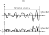
- FIG. 1 is a diagram showing a roughness curve when calculating an arithmetic mean roughness.
- a separator for a lithium secondary battery including:
- the separator for a lithium secondary is provided with a porous polymer substrate.
- the porous polymer substrate may cause pore blocking (shutdown), when the temperature of a battery is increased due to an abnormal response of the battery. In this manner, it is possible to prevent the problems of ignition and explosion of the battery caused by overcharge.
- the porous polymer substrate is not particularly limited, as long as it may be used generally as a material for a separator for a lithium secondary battery.
- the porous polymer substrate may be a thin film including a polymeric material, and non-limiting examples of such a polymeric material include at least one selected from polymer resins, such as polyolefin resin, polyethylene terephthalate, polybutylene terephthalate, polyacetal, polyamide, polycarbonate, polyimide, polyetherether ketone, polyether sulfone, polyphenylene oxide, polyphenylene sulfide, and polyethylene naphthalene.
- polymer resins such as polyolefin resin, polyethylene terephthalate, polybutylene terephthalate, polyacetal, polyamide, polycarbonate, polyimide, polyetherether ketone, polyether sulfone, polyphenylene oxide, polyphenylene sulfide, and polyethylene naphthalene.
- the porous polymer substrate may include a non-woven fabric or a porous polymer film made of such a polymeric material, or a laminate of two or more layers thereof.
- the porous polymer substrate is any one of the following a) to e):
- the pore size and porosity of the porous polymer substrate may be 0.01-0.09 ⁇ m, and the porosity may be 10-95%.
- the porosity and pore size of the porous polymer substrate may be determined from scanning electron microscopic (SEM) images, by using a mercury porosimeter or capillary flow porosimeter, or through the BET6-point method based on nitrogen gas adsorption flow using a porosimetry analyzer (e.g. Belsorp-II mini, Bell Japan Inc.).
- SEM scanning electron microscopic
- the separator for a lithium secondary battery according to an embodiment of the present disclosure is provided with an organic/inorganic composite porous layer on at least one surface of the porous polymer substrate.
- the organic/inorganic composite porous layer includes inorganic particles and a binder polymer which attaches the inorganic particles to one another so that they may retain their binding states (i.e. the binder polymer interconnects and fixes the inorganic particles), and the inorganic particles may be bound to the porous polymer substrate by the binder polymer.
- the organic/inorganic composite porous layer prevents the porous polymer substrate from undergoing severe heat shrinking behavior, and thus can improve the safety of the separator.
- the organic/inorganic composite porous layer may be disposed on both surfaces of the porous polymer substrate.
- the organic/inorganic composite porous layer is disposed on both surfaces of the porous polymer substrate, it is possible to easily prevent the separator from being rolled in one direction due to the curling at one side of the porous polymer substrate where the organic/inorganic composite porous layer is not disposed.
- the inorganic particles have a BET specific surface area of 50-150 m 2 /g.
- the BET specific surface area of the inorganic particles is 50-150 m 2 /g, the inorganic particles may be distributed more densely per unit area of the separator, thereby providing the separator with improved thermal safety.
- the inorganic particles contained in the organic/inorganic composite porous layer may surround the nail to prevent a direct short-circuit between a positive electrode and a negative electrode.
- the pore size of the organic/inorganic composite porous layer containing the inorganic particles may be 100 nm or less corresponding to the pore size of the porous polymer substrate. Therefore, it is possible to realize pore uniformity in the thickness direction of the separator.
- the BET specific surface area of the inorganic particles is less than 50 m 2 /g, it is difficult to ensure the thermal safety of the separator, and it is also difficult to ensure nail penetration safety, since the inorganic particles cannot surround the nail.
- the pore size of the organic/inorganic composite porous layer containing the inorganic particles becomes larger than 100 nm, and thus the battery shows a high self-discharge rate, and excessive current leakage occurs upon the full charge, thereby making it difficult to realize a profound charge depth.
- the BET specific surface area of the inorganic particles is larger than 150 m 2 /g, the pores among the inorganic particles becomes excessively narrow to cause a decrease in ion conductivity, and thus it is difficult to realize quick charging and high-rate discharging of the lithium secondary battery including the separator.
- the BET specific surface area of the inorganic particles may be 51 m 2 /g or more, 56 m 2 /g or more, 57 m 2 /g or more, 60 m 2 /g or more, 65 m 2 /g or more, 70 m 2 /g or more, 75 m 2 /g or more, 80 m 2 /g or more, 90 m 2 /g or more, 100 m 2 /g or more, 110 m 2 /g or more, 115 m 2 /g or more, or 120 m 2 /g or more, and 130 m 2 /g or less, 120 m 2 /g or less, 115 m 2 /g or less, 110 m 2 /g or less, 100 m 2 /g or less, 90 m 2 /g or less, 80 m 2 /g or less, 75 m 2 /g or less, 70 m 2 /g or less, 65 m 2 /g
- the BET specific surface area of the inorganic particles satisfies the above-defined range, it is possible to ensure the thermal dimensional safety and nail penetration safety of the separator with ease.
- the BET specific surface area of the inorganic particles is 50-75 m 2 /g, it is possible to ensure the dispersion stability of the inorganic particles, even when an excessive amount of dispersant is not used during the dispersion of the inorganic particles.
- the BET specific surface area of the inorganic particles may be determined by the method of ASTM C1069.
- the inorganic particles may have an average particle diameter (D50) of 20 nm or more, 23 nm or more, 24 nm or more, 30 nm or more, or 39 nm or more, and 47 nm or less, 40 nm or less, 39 nm or less, 30 nm or less, 24 nm or less, or 23 nm or less.
- D50 average particle diameter
- the inorganic particles may be distributed more densely per unit area of the separator, thereby providing the separator with improved thermal safety.
- the inorganic particles contained in the organic/inorganic composite porous layer may surround the nail to prevent a direct short-circuit between a positive electrode and a negative electrode.
- the pore size of the organic/inorganic composite porous layer containing the inorganic particles may be 100 nm or less corresponding to the pore size of the porous polymer substrate. Therefore, it is possible to realize pore uniformity in the thickness direction of the separator.
- the term ⁇ average particle diameter of the inorganic particles' means a D50 particle diameter
- ⁇ D50 particle diameter' means a particle diameter at a point of 50% in the accumulated particle number distribution depending on particle diameter.
- the particle diameter may be determined by using a laser diffraction method. Particularly, a powder to be analyzed is dispersed in a dispersion medium and introduced to a commercially available laser diffraction particle size analyzer (e.g. Microtrac S3500), and then a difference in diffraction pattern depending on particle size is determined, when particles pass through laser beams, and then particle size distribution is calculated. Then, the particle diameter at a point of 50% of the particle number accumulated distribution depending on particle diameter is calculated to determine D50.
- the average particle diameter may refer to the average particle diameter of primary particles.
- the inorganic particles may include fumed inorganic particles.
- fumed inorganic particles refer to inorganic particles which form secondary particles through the interconnection thereof by the collision of elementary particles formed by hydrolysis in a flame at 1,000°C or higher, wherein the secondary particles form three-dimensional aggregates (agglomerates).
- the inorganic particles include fumed inorganic particles, it is easy to form inorganic particles having a BET specific surface area of 50-150 m 2 /g.
- the inorganic particles include fumed inorganic particles, it is easy to form inorganic particles having an average particle diameter (D50) of 20-47 nm based on primary particles.
- D50 average particle diameter
- fumed inorganic particles may include fumed alumina, fumed silica, fumed titanium dioxide, or two or more of them.
- the binder polymer may include polyvinylidene fluoride, polyvinylidene fluoride-co-hexafluoropropylene, polyvinylidene fluoride-co-chlorotrifluoroethylene, polyvinylidene fluoride-co-tetrafluoroethylene, polyvinylidene fluoride-co-trichloroethylene, acrylic copolymer , styrene-butadiene copolymer, polyacrylic acid, polymethyl methacrylate, polybutyl acrylate, polyacrylonitrile, polyvinyl pyrrolidone, polyvinyl alcohol, polyvinyl acetate, polyethylene-co-vinyl acetate, polyethylene oxide, polyarylate, cellulose acetate, cellulose acetate butyrate, cellulose acetate propionate, cyanoethyl pullulan, cyanoethyl polyvinyl alcohol, cyanoethy
- the acrylic copolymer may include, but is not limited to: ethyl acrylate-acrylic acid-N,N-dimethyl acrylamide copolymer, ethyl acrylate-acrylic acid-2-(dimethylamino)ethyl acrylate copolymer, ethyl acrylate-acrylic acid-N,N-diethylacrylamide copolymer, ethyl acrylate-acrylic acid-2-(diethylamino)ethyl acrylate copolymer, or two or more of them.
- the weight ratio of the inorganic particles to the binder polymer may be 50:50-99.5:0.5, or 70:30-97:3.
- the weight ratio of the inorganic particles to the binder polymer satisfies the above-define range, it is possible to ensure sufficient vacant spaces formed among the inorganic particles, while ensuring sufficient adhesion among the inorganic particles.
- the organic/inorganic composite porous layer may have a structure in which the inorganic particles are bound to one another by the binder polymer, while they are packed in contact with one another. In this manner, interstitial volumes are formed among the inorganic filler particles, and the interstitial volumes become vacant spaces to form pores.
- the organic/inorganic composite porous layer may have a pore size of 5-100 nm, or 10-90 nm.
- the pore size of the organic/inorganic composite porous layer satisfies the above-defined range, the pore size of the organic/inorganic composite porous layer is one corresponding to the pore size of the porous polymer substrate. Therefore, it is possible to realize the pore uniformity with ease in the thickness direction. It is also possible to improve the self-discharge rate of a battery.
- the pore size of the organic/inorganic composite porous layer may be determined by using the capillary flow porometry.
- the capillary flow porometry measures the diameter of the smallest pore in the thickness direction. Therefore, in order to determine the average pore size of the organic/inorganic composite porous layer alone by the capillary flow porometry, it is required to separate the organic/inorganic composite porous layer from the crosslinked structure-containing polyolefin porous substrate, and to surround the separated organic/inorganic composite porous layer with a non-woven fabric capable of supporting the same.
- the non-woven fabric should have a significantly larger pore size as compare to the pore size of the organic/inorganic composite porous layer.
- the organic/inorganic composite porous layer may have a porosity of 5-95%, 10-95%, 20-90%, or 30-80%.
- the porosity corresponds to a value obtained by subtracting the volume expressed by the weight and density of each ingredient forming the organic/inorganic composite porous layer from the volume calculated from the thickness, width and length of the organic/inorganic composite porous coating layer.
- the porosity of the organic/inorganic composite porous layer may be determined from scanning electron microscopic (SEM) images, by using a mercury porosimeter or capillary flow porosimeter, or through the BET6-point method based on nitrogen gas adsorption flow using a porosimetry analyzer (e.g. Belsorp-II mini, Bell Japan Inc.).
- SEM scanning electron microscopic
- the thickness of the organic/inorganic composite porous layer is larger than the thickness of the porous polymer substrate.
- the thickness of the organic/inorganic composite porous layer is larger than the thickness of the porous polymer substrate, it is possible to prevent a short-circuit between a positive electrode and a negative electrode, or between an electrode and a nail, even though the nail penetrates through the organic/inorganic composite porous layer to cause damages upon the porous polymer substrate.
- the inorganic particles contained in the organic/inorganic composite porous layer may surround the nail upon the nail penetration, and can prevent a direct short-circuit between materials having conductivity, for example, between a positive electrode and a negative electrode, or between an electrode and the nail.
- the organic/inorganic composite porous layer may have a thickness corresponding to 1.01 times or more, 1.09 times or more, 1.1 times or more, 1.5 times or more, 1.8 times or more, 2.2 times or more, 2.8 times or more, or 3 times or more, and 5 times or less, 3 times or less, 2.8 times or less, 2.2 times or less, 1.8 times or less, 1.5 times or less, 1.1 times or less, or 1.09 times or less, based on the thickness of the porous polymer substrate.
- the thickness of the organic/inorganic composite porous layer satisfies the above-defined range, it is possible to easily prevent damages upon the porous polymer substrate caused by penetration of a nail through the organic/inorganic composite porous layer, and a short-circuit caused thereby, while maintaining the pore blocking effect derived from the porous polymer substrate.
- the thickness of the organic/inorganic composite porous layer is 1.1-3 times of the thickness of the porous polymer substrate, it is possible to easily prevent a short-circuit caused by a nail, while ensuring the mechanical strength of the porous polymer substrate.
- the organic/inorganic composite porous layer may have a thickness of 5-15 ⁇ m, 6-12 ⁇ m, or 7-10 ⁇ m.
- the thickness of the organic/inorganic composite porous layer satisfies the above-defined range, it is possible to prevent the porous polymer substrate from being damaged by a nail penetrating through the thick organic/inorganic composite porous layer, and to prevent a decrease in battery capacity and an increase in resistance, caused by an excessively larger thickness of the separator.
- the porous polymer substrate may have a thickness of 3 ⁇ m or more, 3.5 ⁇ m or more, 4.5 ⁇ m or more, 5 ⁇ m or more, 5.5 ⁇ m or more, 6.5 ⁇ m or more, or 9 ⁇ m or more, and 10 ⁇ m or less, 9 ⁇ m or less, 6.5 ⁇ m or less, 5.5 ⁇ m or less, 5 ⁇ m or less, 4.5 ⁇ m or less, or 3.5 ⁇ m or less.
- the thickness of the porous polymer substrate satisfies the above-defined range, it is possible to maintain a pore blocking effect derived from the porous polymer substrate, while preventing the problem of damages upon the separator during the use of a battery. It is also possible to prevent a decrease in battery capacity and an increase in resistance, caused by an excessively larger thickness of the separator.
- the thickness of the organic/inorganic composite porous layer corresponds to the sum of the organic/inorganic composite porous layers each disposed on one surface of the porous polymer substrate.
- the thickness of the organic/inorganic composite porous layer may be calculated by subtracting the thickness of the porous polymer substrate from the average value of the thickness values measured at 9 positions of a sample.
- the weight of the organic/inorganic composite porous layer may be 50-99 wt%, or 70-90 wt% based on the total weight of the separator.
- the weight of the organic/inorganic composite porous layer satisfies the above-defined range, it is possible to prevent damages upon the porous polymer substrate, caused by penetration of a nail through the organic/inorganic composite porous layer, by virtue of a high proportion of the organic/inorganic composite porous layer in the separator, and to prevent a short-circuit caused thereby.
- the weight of the organic/inorganic composite porous layer may be determined by subtracting the weight of the porous polymer substrate from the total weight of the separator.
- the surface of the organic/inorganic composite porous layer may have an arithmetic mean roughness (Ra) of 100-500 nm.
- the surface of the organic/inorganic composite porous layer may have an arithmetic mean roughness of 150 nm or more, 210 nm or more, 230 nm or more, 350 nm or more, 355 nm or more, or 390 nm or more, and 420 nm or less, 390 nm or less, 355 nm or less, 350 nm or less, 230 nm or less, or 210 nm or less.
- the organic/inorganic composite porous layer When the arithmetic mean roughness of the surface of the organic/inorganic composite porous layer satisfies the above-defined range, the organic/inorganic composite porous layer has a uniform thickness to minimize the interfacial resistance between an electrode and the separator and to allow uniform lithium ion transport during charge/discharge, thereby providing a battery with improved life characteristics.
- the arithmetic mean roughness of the surface of the organic/inorganic composite porous layer is less than 100 nm, the pores of the organic/inorganic composite porous layer become narrow to cause the problem of an increase in resistance.
- the arithmetic mean roughness of the surface of the organic/inorganic composite porous layer is larger than 500 nm, the pores of the organic/inorganic composite porous layer become significantly large, thereby facilitating current leakage. In this case, there is a problem of self-discharge.
- ⁇ arithmetic mean roughness' refers to a roughness curve expressed by the following Formula 1, when a reference length of L is extracted in the mean line direction of the roughness curve in the roughness distribution of the surface determined sequentially from the start point, as depicted hereinbelow, the mean line direction is taken as x axis, and the height direction is taken as Y axis.
- R a 1 L ⁇ 0 L f x dx
- the arithmetic mean roughness may be determined by using an optical profiler (NV-2700) available from Nano System.
- NV-2700 optical profiler
- the separator for a lithium secondary battery according to an embodiment of the present disclosure has excellent heat resistance, and thus may not be broken even at 190°C, which is significantly higher than the meltdown temperature of the conventional separator.
- the separator has excellent heat resistance, and thus may show a heat shrinkage of 10% or less, 0.1-10%, 0.2-7%, or 0.5-3%, each in the machine direction (MD) and the transverse direction (TD), as measured after allowing the separator to stand at 190°C for 1 hour.
- the separator includes inorganic particles having a BET specific surface area of 50-150 m 2 /g to facilitate light scattering and includes a porous polymer substrate to cause a shutdown phenomenon.
- the separator is not broken at 190°C, and thus may show a ratio of the light transmission after being allowed to stand at 25°C for 1 hour based on the light transmission after being allowed to stand at 190°C for 1 hour of 1.2 or more, 2.0 or more, 1.2-20.0, or 2.0-20.0.
- the light transmission may be determined by using a UV-Vis spectrometer capable of analysis in a wavelength range of 190-900 nm.
- the separator may have a total thickness of 8-25 ⁇ m, 11-21 ⁇ m, or 13-19 ⁇ m.
- the thickness of the separator satisfies the above-defined range, it is possible to improve the safety, while preventing a decrease in battery capacity and an increase in resistance, caused by an excessively large thickness of the separator.
- the separator for a lithium secondary battery according to an embodiment of the present disclosure may be obtained by the following method, but is not limited thereto.
- a separator for a lithium secondary battery including the steps of:
- the porous polymer substrate may be obtained from the above-mentioned materials by forming pores therein through a conventional process known to those skilled in the art for ensuring high air permeability and porosity, such as a wet process using a solvent, a diluent or a pore forming agent or a dry process based on stretching .
- the slurry for forming an organic/inorganic composite porous layer may be prepared by dissolving or dispersing the binder polymer in a solvent for the binder polymer, adding the inorganic particles thereto and dispersing them therein.
- the method for preparing the slurry is not limited thereto.
- the solvent for the binder polymer may function as a solvent capable of dissolving the binder polymer, or as a dispersion medium not capable of dissolving the binder polymer but capable of dispersing the binder polymer.
- the solvent for the binder polymer may include N-methyl-2-pyrrolidone, acetone, methyl ethyl ketone, dimethylformamide, dimethylacetamide, methanol, ethanol, isopropyl alcohol, or two or more organic solvents of them, or water.
- the slurry for forming an organic/inorganic composite porous layer may be coated on at one surface of the porous polymer substrate.
- Non-limiting examples of the method for coating the slurry include dip coating, die coating, roll coating, comma coating, microgravure coating, doctor blade coating, reverse roll coating, Mayer bar coating, direct roll coating, or the like.
- the method may further include a step of carrying out phase separation by using a non-solvent for the binder polymer in a conventional manner known to those skilled in the art, after the slurry for forming an organic/inorganic composite porous layer is coated on at least one surface of the porous polymer substrate.
- the phase separation step may be carried out in order to form a pore structure in the organic/inorganic composite porous layer.
- the coated slurry may be dried by using a conventional drying method used in the manufacture of a separator.
- the coated slurry may be dried by using air for 10 seconds to 30 minutes, 30 seconds to 20 minutes, or 3-10 minutes.
- the drying time is within the above-defined range, it is possible to remove the residual solvent, while not adversely affecting the productivity.
- the above-described separator for a lithium secondary battery may be interposed between a positive electrode and a negative electrode to obtain a lithium secondary battery.
- the lithium secondary battery may include a lithium metal secondary battery, a lithium-ion secondary battery, a lithium polymer secondary battery, a lithium-ion polymer secondary battery, or the like.
- the electrodes used in combination with the separator according to the present disclosure are not particularly limited, and may be obtained by allowing an electrode active material layer containing an electrode active material, a conductive material and a binder to be bound to an electrode current collector through a method generally known in the art.
- the positive electrode active material include, but are not limited to: layered compounds, such as lithium cobalt oxide (LiCoO 2 ) and lithium nickel oxide (LiNiO 2 ), or those compounds substituted with one or more transition metals; lithium manganese oxides such as those represented by the chemical formula of Li 1+x Mn 2-x O 4 (wherein x is 0-0.33), LiMnO 3 , LiMn 2 O 3 and LiMnO 2 ; lithium copper oxide (Li 2 CuO 2 ); vanadium oxides such as LiVsOs, LiV 3 O 4 , V 2 O 5 or Cu 2 V 2 O 7 ; Ni-site type lithium nickel oxides represented by the chemical formula of LiNi 1-x M x O 2 (wherein M is Co, Mn, Al, Cu, Fe, Mg, B or Ga, and x is 0.01-0.3); lithium manganese composite oxides represented by the chemical formula of LiMn 2-x M x O 2 (wherein
- Non-limiting examples of the negative electrode active material include conventional negative electrode active materials that may be used for the negative electrodes for conventional electrochemical devices. Particularly, lithium-intercalating materials, such as lithium metal or lithium alloys, carbon, petroleum coke, activated carbon, graphite or other carbonaceous materials, may be used.
- lithium-intercalating materials such as lithium metal or lithium alloys, carbon, petroleum coke, activated carbon, graphite or other carbonaceous materials.
- Non-limiting examples of the positive electrode current collector include foil made of aluminum, nickel or a combination thereof.
- Non-limiting examples of the negative electrode current collector include foil made of copper, gold, nickel, copper alloys or a combination thereof.
- the conductive material used in each of the negative electrode and the positive electrode may be added in an amount of 1-30 wt% based on the total weight of the active material layer.
- the conductive material is not particularly limited, as long as it causes no chemical change in the corresponding battery and has conductivity.
- the conductive material include: graphite, such as natural graphite or artificial graphite; carbon black, such as acetylene black, Ketjen black, channel black, furnace black, lamp black or thermal black; conductive fibers, such as carbon fibers or metallic fibers; fluorocarbon; metal powder, such as aluminum or nickel powder; conductive whisker, such as zinc oxide or potassium titanate; conductive metal oxide, such as titanium oxide; conductive materials, such as polyphenylene derivatives, or the like.
- graphite such as natural graphite or artificial graphite
- carbon black such as acetylene black, Ketjen black, channel black, furnace black, lamp black or thermal black
- conductive fibers such as carbon fibers or metallic fibers
- fluorocarbon such as aluminum or nickel powder
- conductive whisker such as zinc oxide or potassium titanate
- conductive metal oxide such as titanium oxide
- conductive materials such as polyphenylene derivatives, or the like.
- the binder used in each of the negative electrode and the positive electrode independently is an ingredient which assists binding between the active material and the conductive material and binding to the current collector.
- the binder may be added in an amount of 1-30 wt% based on the total weight of the active material layer.
- binder examples include polyvinylidene fluoride (PVDF), polyacrylic acid (PAA), polyvinyl alcohol, carboxymethyl cellulose (CMC), starch, hydroxypropyl cellulose, regenerated cellulose, polyvinyl pyrrolidone, polytetrafluoroethylene, polyethylene, polypropylene, ethylenepropylene-diene terpolymer (EPDM), sulfonated EPDM, styrene-butadiene rubber, fluoro-rubber, various copolymers, or the like.
- PVDF polyvinylidene fluoride
- PAA polyacrylic acid
- CMC carboxymethyl cellulose
- EPDM ethylenepropylene-diene terpolymer
- EPDM ethylenepropylene-diene terpolymer
- EPDM ethylenepropylene-diene terpolymer
- EPDM ethylenepropylene-diene terpolymer
- EPDM ethylenepropylene-diene ter
- the lithium secondary battery includes an electrolyte, which may include an organic solvent and a lithium salt.
- the electrolyte may include an organic solid electrolyte or an inorganic solid electrolyte.
- organic solvent examples include aprotic organic solvents, such as N-methyl-2-pyrrolidone, ethylene carbonate, propylene carbonate, butylene carbonate, dimethyl carbonate, diethyl carbonate, ⁇ -butyrolactone, 1,2-dimethoxyethane, tetrahydrofuran , 2-methyl tetrahydrofuran, dimethyl sulfoxide, 1,3-dioxolan, formamide, dimethyl formamide, dioxolan, acetonitrile, nitromethane, methyl formate, methyl acetate, triphosphate, trimethoxymethane, dioxolan derivatives, sulfolane , methyl sulfolane , 1,3-dimethyl-2-imidazolidione, propylene carbonate derivatives, tetrahydrofuran derivatives, ethers, methyl propionate, ethyl propionate, or the like.
- aprotic organic solvents
- the lithium salt is a material which can be dissolved in the non-aqueous electrolyte with ease, and particular examples thereof include LiCl, LiBr, LiI, LiClO 4 , LiBF 4 , LiB 10 Cl 10 , LiPF 6 , LiCF 3 SO 3 , LiCF 3 CO 2 , LiAsF 6 , LiSbF 6 , LiAlCl 4 , CH 3 SO 3 Li, (CF 3 SO 2 ) 2 NLi, lithium chloroborane , lithium lower aliphatic carboxylate, lithium tetraphenyl borate, imide, or the like.
- the electrolyte may further include pyridine, triethyl phosphite, triethanolamine, cyclic ethers, ethylene diamine, n-glyme, triamide hexaphosphate, nitrobenzene derivatives, sulfur, quinone imine dyes, N-substituted oxazolidinone, N,N-substituted imidazolidine, ethylene glycol dialkyl ether, ammonium salt, pyrrole, 2-methoxyethaol and aluminum trichloride in order to improve the charge/discharge characteristics, flame resistance, or the like.
- the electrolyte may further include a halogen-containing solvent, such as carbon tetrachloride or trifluoroethylene, in order to impart non-combustibility.
- the electrolyte may further include carbon dioxide gas in order to improve the high-temperature storage characteristics.
- organic solid electrolyte may include polyethylene derivatives, polyethylene oxide derivatives, polypropylene oxide derivatives, phosphate polymer, polyagitation lysine, polyester sulfide, polyvinyl alcohol, polyvinylidene fluoride, polymers containing an ionically dissociable group, or the like.
- the inorganic solid electrolyte may include nitrides, halides and sulfates of Li, such as Li 3 N, LiI, Li 5 NI 2 , Li 3 N-LiI-LiOH, LiSiO 4 , LiSiO 4 -LiI-LiOH, Li 2 SiS 3 , Li 4 SiO 4 , Li 4 SiO 4 -LiI-LiOH and Li 3 PO 4 -Li 2 S-SiS 2 .
- Li such as Li 3 N, LiI, Li 5 NI 2 , Li 3 N-LiI-LiOH, LiSiO 4 , LiSiO 4 -LiI-LiOH, Li 2 SiS 3 , Li 4 SiO 4 , Li 4 SiO 4 -LiI-LiOH and Li 3 PO 4 -Li 2 S-SiS 2 .
- Injection of the electrolyte may be carried out in an adequate step during the process for manufacturing a battery depending on the manufacturing process of a final product and properties required for a final product. In other words, injection of the electrolyte may be carried out before the assemblage of a battery or in the final step of the assemblage of a battery.
- the process for applying the electrode assembly to the battery may include lamination (stacking) and folding of the separator with electrodes, besides a conventional process, winding.
- the separator for a lithium secondary battery may be interposed between the positive electrode and the negative electrode of the lithium secondary battery.
- the separator may be interposed between the adjacent cells or electrodes.
- the electrode assembly may have various structures, such as a simple stack type, a j elly-roll type, a stacked-folded type, a laminated-stacked type, or the like.
- a polyolefin porous film (Asahi Co., ND506, thickness: 5.5 ⁇ m) was prepared as a porous polymer substrate, and the slurry for forming an organic/inorganic composite porous layer was coated on both surfaces of the porous polymer substrate through a dip coating process and dried at 60°C for 3 minutes to obtain a separator.
- each organic/inorganic composite porous layer formed on one surface of the porous polymer substrate had a thickness of 5 ⁇ m, and the total thickness of the organic/inorganic composite porous layers formed on both surfaces of the porous polymer substrate was 10 ⁇ m.
- a separator was obtained in the same manner as Example 1, except that the inorganic particles were changed into fumed alumina (Cabot Co., FA51, BET specific surface area: 51 m 2 /g, average particle diameter (D50) of primary particles: 23 nm).
- each organic/inorganic composite porous layer formed on one surface of the porous polymer substrate had a thickness of 5.0 ⁇ m, and the total thickness of the organic/inorganic composite porous layers formed on both surfaces of the porous polymer substrate was 10.0 ⁇ m.
- a separator was obtained in the same manner as Example 1, except that the porous polymer substrate was changed into a polyolefin porous film (Senior Co., SW506, thickness: 6.5 ⁇ m).
- each organic/inorganic composite porous layer formed on one surface of the porous polymer substrate had a thickness of 5.0 ⁇ m, and the total thickness of the organic/inorganic composite porous layers formed on both surfaces of the porous polymer substrate was 10.0 ⁇ m.
- a separator was obtained in the same manner as Example 1, except that the solid content of the slurry for forming an organic/inorganic composite porous layer was changed into 25%.
- each organic/inorganic composite porous layer formed on one surface of the porous polymer substrate had a thickness of 3.0 ⁇ m, and the total thickness of the organic/inorganic composite porous layers formed on both surfaces of the porous polymer substrate was 6.0 ⁇ m.
- a separator was obtained in the same manner as Example 1, except that the polyolefin porous film (Asahi Co., ND506, thickness: 5.5 ⁇ m) was further stretched at 123°C in the machine direction (MD) and in the transverse direction (TD) by 1.3 times in each direction to form a thin film having a final thickness of 3.5 ⁇ m, and the resultant thin film was used as a porous polymer substrate.
- the polyolefin porous film Asahi Co., ND506, thickness: 5.5 ⁇ m
- each organic/inorganic composite porous layer formed on one surface of the porous polymer substrate had a thickness of 5.0 ⁇ m, and the total thickness of the organic/inorganic composite porous layers formed on both surfaces of the porous polymer substrate was 10 ⁇ m.
- a separator was obtained in the same manner as Example 1, except that the slurry used in Example 1 was taken as the first slurry and applied to one surface of the porous polymer substrate, and the slurry prepared in the same manner as the first slurry, except that 90 wt% of the inorganic particles used in Example 1 were mixed with 10 wt% of pulverized alumina (DAEHAN Ceramics Co., Ltd., ALK-N1, BET specific surface area: 8.9 m 2 /g, average particle diameter (D50) of primary particles: 280 nm), was taken as the second slurry, and the second slurry was applied sequentially to the other surface of the porous polymer substrate, through a micro-gravure process.
- DAEHAN Ceramics Co., Ltd. ALK-N1, BET specific surface area: 8.9 m 2 /g, average particle diameter (D50) of primary particles: 280 nm
- the total inorganic particles contained in the second slurry had a BET specific surface area of 56 m 2 /g.
- each organic/inorganic composite porous layer formed on one surface of the porous polymer substrate had a thickness of 5.0 ⁇ m, and the total thickness of the organic/inorganic composite porous layers formed on both surfaces of the porous polymer substrate was 10 ⁇ m.
- a separator was obtained in the same manner as Example 1, except that the polyolefin porous film (Senior Co., SW506, thickness: 6.5 ⁇ m) was further stretched at 123°C in the machine direction (MD) and in the transverse direction (TD) by 1.2 times in each direction to form a thin film having a final thickness of 4.5 ⁇ m, and the resultant thin film was used as a porous polymer substrate.
- the polyolefin porous film (Senior Co., SW506, thickness: 6.5 ⁇ m) was further stretched at 123°C in the machine direction (MD) and in the transverse direction (TD) by 1.2 times in each direction to form a thin film having a final thickness of 4.5 ⁇ m, and the resultant thin film was used as a porous polymer substrate.
- a separator was obtained in the same manner as Example 1, except that 95 wt% of the inorganic particles used in Example 1 were mixed with 5 wt% of pulverized alumina (DAEHAN Ceramics Co., Ltd., ALK-N1, BET specific surface area: 8.9 m 2 /g, average particle diameter of primary particles (D50): 280 nm) so that the total BET specific surface area of the inorganic particles might be 57 m 2 /g.
- D50 pulverized alumina
- each organic/inorganic composite porous layer formed on one surface of the porous polymer substrate had a thickness of 5.0 ⁇ m, and the total thickness of the organic/inorganic composite porous layers formed on both surfaces of the porous polymer substrate was 10 ⁇ m.
- a separator was obtained in the same manner as Example 1, except that the inorganic particles were changed into fumed alumina (Evonik Co., Alu130, BET specific surface area: 130 m 2 /g, average particle diameter of primary particles: 20 nm).
- each organic/inorganic composite porous layer formed on one surface of the porous polymer substrate had a thickness of 5.0 ⁇ m, and the total thickness of the organic/inorganic composite porous layers formed on both surfaces of the porous polymer substrate was 10 ⁇ m.
- a separator was obtained in the same manner as Example 1, except that 90 wt% of the inorganic particles used in Example 9 were mixed with 10 wt% of pulverized alumina (DAEHAN Ceramics Co., Ltd., ALK-N1, BET specific surface area: 8.9 m 2 /g, average particle diameter of primary particles (D50): 280 nm) so that the total BET specific surface area of the inorganic particles might be 115 m 2 /g.
- D50 average particle diameter of primary particles
- each organic/inorganic composite porous layer formed on one surface of the porous polymer substrate had a thickness of 5.0 ⁇ m, and the total thickness of the organic/inorganic composite porous layers formed on both surfaces of the porous polymer substrate was 10 ⁇ m.
- a separator was obtained in the same manner as Example 4, except that a polyolefin porous film (Senior Co., SW309H, thickness: 9 ⁇ m) was used as a porous polymer substrate.
- a polyolefin porous film (Senior Co., SW309H, thickness: 9 ⁇ m) was used as a porous polymer substrate.
- each organic/inorganic composite porous layer formed on one surface of the porous polymer substrate had a thickness of 3 ⁇ m, and the total thickness of the organic/inorganic composite porous layers formed on both surfaces of the porous polymer substrate was 6 ⁇ m.
- a separator was obtained in the same manner as Example 1, except that 40 wt% of the inorganic particles used in Example 9 were mixed with 60 wt% of pulverized alumina (DAEHAN Ceramics Co., Ltd., ALK-N1, BET specific surface area: 8.9 m 2 /g, average particle diameter of primary particles (D50): 280 nm) so that the total BET specific surface area of the inorganic particles might be 58 m 2 /g.
- D50 pulverized alumina
- each organic/inorganic composite porous layer formed on one surface of the porous polymer substrate had a thickness of 5.0 ⁇ m, and the total thickness of the organic/inorganic composite porous layers formed on both surfaces of the porous polymer substrate was 10 ⁇ m.
- a separator was obtained in the same manner as Example 1, except that no porous polymer substrate was used, the slurry for forming an organic/inorganic composite porous layer was coated on one surface of a PET film treated with a release agent and having a thickness of 20 ⁇ m through a doctor blade coating process and dried at 80°C for 5 minutes to form an organic/inorganic composite porous layer having a thickness of 15 ⁇ m, and the organic/inorganic composite porous layer was peeled from the PET film.
- a separator was obtained in the same manner as Example 1, except that alumina (DAEHAN Ceramics Co., Ltd., ALK-N1, BET specific surface area: 8.9 m 2 /g, average particle diameter of primary particles (D50): 280 nm) were used as inorganic particles.
- alumina DAEHAN Ceramics Co., Ltd., ALK-N1, BET specific surface area: 8.9 m 2 /g, average particle diameter of primary particles (D50): 280 nm
- a separator was obtained in the same manner as Example 1, except that alumina (DAEHAN Ceramics Co., Ltd., ALK-N1, BET specific surface area: 8.9 m 2 /g, average particle diameter of primary particles (D50): 280 nm) mixed with fumed alumina (Evonik Co., Alu65, BET specific surface area: 65 m 2 /g, average particle diameter (D50) of primary particles: 24 nm) at a ratio of 50:50 were used as inorganic particles.
- alumina DAEHAN Ceramics Co., Ltd., ALK-N1, BET specific surface area: 8.9 m 2 /g, average particle diameter of primary particles (D50): 280 nm
- fumed alumina Evonik Co., Alu65, BET specific surface area: 65 m 2 /g, average particle diameter (D50) of primary particles: 24 nm
- Table 1 shows the thickness and weight of the porous polymer substrate, thickness and weight of the organic/inorganic composite porous layer, thickness of the organic/inorganic composite porous layer based on the total thickness of the separator, weight of the organic/inorganic composite porous layer based on the total weight of the separator, BET specific surface area of the organic/inorganic composite porous layer, average particle diameter (D50) of the inorganic particles, and the arithmetic mean roughness (Ra) of the surface of the organic/inorganic composite porous layer, in the separator according to each of Examples 1-10 and Comparative Examples 1-5.
- the thickness of the organic/inorganic composite porous layer was determined by subtracting the thickness of the porous polymer substrate from the average value of thickness of the separator measured at 9 positions of each sample.
- the total weight of the separator was determined as average weight of 5 measurements of a sample having a unit area (5 cm x 5 cm), and the weight of the organic/inorganic composite porous layer was calculated by subtracting the weight of the porous polymer substrate, determined in the same manner as the total weight of the separator, from the total weight of the separator.
- the BET specific surface area of inorganic particles was determined by the method of ASTM C1069.
- the arithmetic mean roughness (Ra) of the surface of the organic/inorganic composite porous layer was determined by using an optical profiler (NV-2700) available from Nano System Co. as follows.
- a separator sample was taken in a square shape (5 cm (machine direction) x 5 cm (transverse direction)), the sample was disposed on a stage maintained at 23°C and set with a WSI filter, and then the arithmetic mean roughness of the surface was determined. Then, the arithmetic mean roughness of the surface was calculated through Nanomap program, the determination was repeated 5 times in the same manner as described above, and the intermediate value was suggested as a representative value.
- Table 2 shows the heat shrinkage at 190°C in the machine direction (MD) and the transverse direction (TD), nail penetration safety, overcharge safety and Hi-pot test results of the separator according to each of Examples 1-10 and Comparative Examples 1-5.
- 'o' represents ignition of the battery and 'x' represents no ignition.
- the heat shrinkage of the separator according to each of Examples 1-10 and Comparative Examples 1-5 at 190°C in the machine direction (MD) and the transverse direction (TD) was determined by cutting the separator according to each of Examples 1-10 and Comparative Examples 1-5 into a square shape with a size of MD 10 cm x TD 10 cm, allowing the separator sample to stand in a constant-temperature oven maintained at 190°C, and measuring a change in length by using a ruler.
- the separator according to each of Examples 1-10 and Comparative Examples 1-5 was used to manufacture a lithium secondary battery, the lithium secondary battery was fully charged under a voltage of 4.2 V, a nail having a diameter of 2.5 mm was allowed to penetrate through the center of the battery, and occurrence of the battery ignition or not was observed.
- ⁇ o' represents ignition of the battery and 'x' represents no ignition.
- the lithium secondary battery was obtained as follows.
- the negative electrode slurry was coated on a copper current collector at a loading amount of 3.8 mAh/cm 2 , followed by drying, to obtain a negative electrode.
- LiNi 0.8 Co 0.1 Mn 0.1 O 2 as a positive electrode active material, denka black as a conductive material and polyvinylidene fluoride (PVDF) as a binder were added to N-methyl-2-pyrrolidone (NMP) as a solvent at a weight ratio of 96:2:2 to prepare a positive electrode active material slurry.
- the positive electrode active material slurry was coated on a sheet-like aluminum current collector, followed by drying, to form a positive electrode active material layer with a final positive electrode loading amount of 3.4 mAh/cm 2 .
- the separator according to each of Examples and Comparative Examples was interposed between the negative electrode and the positive electrode obtained as described above, and a non-aqueous electrolyte (1 M LiPF 6 , ethylene carbonate (EC)/propylene carbonate (PC)/diethyl carbonate (DEC), volume ratio 3:3:4) was injected thereto to obtain a lithium secondary battery.
- a non-aqueous electrolyte (1 M LiPF 6 , ethylene carbonate (EC)/propylene carbonate (PC)/diethyl carbonate (DEC), volume ratio 3:3:4
- the separator according to each of Examples 1-10 and Comparative Examples 1-5 was used to manufacture a lithium secondary battery, the lithium secondary battery was fully charged under a voltage of 4.2 V, and the fully charged battery was charged at room temperature in a constant-current mode of 0.2 C and continuously charged until the voltage reached 8.5 V or the charge capacity reached 200% of the designed capacity. In this manner, the overcharge safety of the battery was determined.
- 'o' represents a battery satisfying overcharge safety
- 'x' represents a battery not satisfying overcharge safety.
- the lithium secondary battery was obtained in the above-described manner.
- the separator according to each of Examples 1-10 shows excellent results in terms of heat shrinkage at 190°C in the machine direction and the transverse direction, nail penetration safety, overcharge safety and Hi-pot test results.
- the separator according to Comparative Example 1 cannot ensure nail penetration safety due to the thickness of the organic/inorganic composite porous layer smaller than the thickness of the porous polymer substrate.
- the separator shows a poor heat shrinkage at 190°C in the machine direction and the transverse direction.
- the separator according to Comparative Example 2 cannot ensure the condition of the arithmetic mean roughness of the surface of the organic/inorganic composite porous layer, i.e. 100-500 nm, and thus cannot ensure nail penetration safety and overcharge safety and cannot pass the Hi-pot test.
- the separator shows a poor heat shrinkage at 190°C in the machine direction and the transverse direction.
- the separator according to Comparative Example 3 includes no porous polymer substrate, and thus cannot ensure overcharge safety, and cannot pass the Hi-pot test.
- Each of the separators according to Comparative Examples 4 and 5 uses inorganic particles having a BET specific surface area of less than 50 m 2 /g, and thus cannot ensure nail penetration safety, and shows a poor heat shrinkage at 190°C in the machine direction and the transverse direction.
Landscapes
- Chemical & Material Sciences (AREA)
- Chemical Kinetics & Catalysis (AREA)
- Electrochemistry (AREA)
- General Chemical & Material Sciences (AREA)
- Engineering & Computer Science (AREA)
- Manufacturing & Machinery (AREA)
- Inorganic Chemistry (AREA)
- Materials Engineering (AREA)
- Composite Materials (AREA)
- Ceramic Engineering (AREA)
- Cell Separators (AREA)
- Secondary Cells (AREA)
Applications Claiming Priority (2)
| Application Number | Priority Date | Filing Date | Title |
|---|---|---|---|
| KR20210010310 | 2021-01-25 | ||
| PCT/KR2022/001334 WO2022158951A2 (fr) | 2021-01-25 | 2022-01-25 | Séparateur pour batterie secondaire au lithium et batterie secondaire au lithium comprenant celui-ci |
Publications (1)
| Publication Number | Publication Date |
|---|---|
| EP4184699A2 true EP4184699A2 (fr) | 2023-05-24 |
Family
ID=82548960
Family Applications (1)
| Application Number | Title | Priority Date | Filing Date |
|---|---|---|---|
| EP22742927.1A Pending EP4184699A2 (fr) | 2021-01-25 | 2022-01-25 | Séparateur pour batterie secondaire au lithium et batterie secondaire au lithium comprenant celui-ci |
Country Status (6)
| Country | Link |
|---|---|
| US (1) | US20230223659A1 (fr) |
| EP (1) | EP4184699A2 (fr) |
| JP (1) | JP2023529141A (fr) |
| KR (1) | KR20220107984A (fr) |
| CN (1) | CN115668623A (fr) |
| WO (1) | WO2022158951A2 (fr) |
Cited By (1)
| Publication number | Priority date | Publication date | Assignee | Title |
|---|---|---|---|---|
| EP4300696A3 (fr) * | 2022-06-09 | 2024-03-27 | SK Innovation Co., Ltd. | Séparateur, procédé de fabrication de séparateur, et dispositif électrochimique comprenant un séparateur |
Families Citing this family (1)
| Publication number | Priority date | Publication date | Assignee | Title |
|---|---|---|---|---|
| CN117239220B (zh) * | 2023-11-14 | 2024-02-23 | 珠海冠宇电池股份有限公司 | 一种电芯 |
Family Cites Families (6)
| Publication number | Priority date | Publication date | Assignee | Title |
|---|---|---|---|---|
| WO2013080867A1 (fr) * | 2011-11-28 | 2013-06-06 | 東レ株式会社 | Film poreux, séparateur pour dispositif de stockage électrique et dispositif de stockage électrique |
| JP6545461B2 (ja) * | 2012-03-02 | 2019-07-17 | コーネル・ユニバーシティーCornell University | ナノファイバーを含むリチウムイオン電池 |
| EP2806483B1 (fr) * | 2012-11-30 | 2020-01-01 | LG Chem, Ltd. | Membrane de séparation de batterie secondaire contenant des couches de revêtement à double porosité en particules inorganiques ayant différentes propriétés de surface et procédé de fabrication de ladite membrane de séparation |
| JP7409777B2 (ja) * | 2019-03-04 | 2024-01-09 | 旭化成株式会社 | リチウムイオン二次電池用セパレータ |
| EP3966881A1 (fr) * | 2019-05-07 | 2022-03-16 | Evonik Operations GmbH | Séparateur de batterie lithium-ion revêtu d'alumine traitée en surface |
| KR20210010310A (ko) | 2019-07-18 | 2021-01-27 | 롬엔드하스전자재료코리아유한회사 | 복수 종의 호스트 재료 및 이를 포함하는 유기 전계 발광 소자 |
-
2022
- 2022-01-25 EP EP22742927.1A patent/EP4184699A2/fr active Pending
- 2022-01-25 KR KR1020220011083A patent/KR20220107984A/ko active Search and Examination
- 2022-01-25 WO PCT/KR2022/001334 patent/WO2022158951A2/fr unknown
- 2022-01-25 JP JP2022574286A patent/JP2023529141A/ja active Pending
- 2022-01-25 US US18/008,801 patent/US20230223659A1/en active Pending
- 2022-01-25 CN CN202280004852.0A patent/CN115668623A/zh active Pending
Cited By (1)
| Publication number | Priority date | Publication date | Assignee | Title |
|---|---|---|---|---|
| EP4300696A3 (fr) * | 2022-06-09 | 2024-03-27 | SK Innovation Co., Ltd. | Séparateur, procédé de fabrication de séparateur, et dispositif électrochimique comprenant un séparateur |
Also Published As
| Publication number | Publication date |
|---|---|
| CN115668623A (zh) | 2023-01-31 |
| KR20220107984A (ko) | 2022-08-02 |
| JP2023529141A (ja) | 2023-07-07 |
| WO2022158951A2 (fr) | 2022-07-28 |
| WO2022158951A3 (fr) | 2022-09-15 |
| US20230223659A1 (en) | 2023-07-13 |
Similar Documents
| Publication | Publication Date | Title |
|---|---|---|
| EP3396746B1 (fr) | Électrode positive pour une batterie secondaire, procédé de fabrication et batterie au lithium comportant l'électrode positive | |
| US8343388B2 (en) | Electrode having porous active coating layer, manufacturing method thereof and electrochemical device containing the same | |
| US10637097B2 (en) | Organic/inorganic composite electrolyte, electrode-electrolyte assembly and lithium secondary battery including the same, and manufacturing method of the electrode-electrolyte assembly | |
| EP2696392B1 (fr) | Séparateur d'accumulateur non aqueux et accumulateur non aqueux | |
| KR20170141141A (ko) | 이차전지용 전극 및 이를 포함하는 리튬 이차 전지 | |
| EP4184699A2 (fr) | Séparateur pour batterie secondaire au lithium et batterie secondaire au lithium comprenant celui-ci | |
| KR102071489B1 (ko) | 활물질 입자의 평균 입경이 상이한 코팅층들을 포함하는 이차전지용 전극 | |
| CN111684627B (zh) | 锂二次电池用负极活性材料和包含其的锂二次电池用负极 | |
| EP4138202A1 (fr) | Séparateur pour batterie secondaire, son procédé de fabrication et batterie secondaire le comprenant | |
| EP3863090A1 (fr) | Matériau actif d'anode pour batterie secondaire, son procédé de préparation, anode pour batterie secondaire le comprenant, et batterie secondaire au lithium | |
| KR102042464B1 (ko) | 이온 전도도가 향상된 내열성 코팅층을 포함하는 분리막의 제조 방법 및 이로부터 제조되는 분리막 | |
| CN114127987A (zh) | 具有降低的水分反应性的高镍电极片及其制造方法 | |
| EP4184698A2 (fr) | Séparateur pour batterie secondaire au lithium et batterie secondaire au lithium le comprenant | |
| KR101757964B1 (ko) | 리튬이차전지의 양극 형성용 조성물, 그리고 이를 이용하여 제조한 양극 및 리튬이차전지 | |
| EP4156324A1 (fr) | Anode pour batterie rechargeable au lithium et batterie rechargeable au lithium la comprenant | |
| KR20210120686A (ko) | 음극의 제조방법 | |
| EP4181305A1 (fr) | Séparateur et batterie secondaire le comprenant | |
| EP4152508A1 (fr) | Cellule de batterie et son procédé de fabrication | |
| KR101613281B1 (ko) | 전극조립체의 제조방법, 그 전극조립체 및 이를 포함하는 이차전지 | |
| KR102294858B1 (ko) | 이차전지용 분리막 제조 방법 | |
| EP3863082A1 (fr) | Procédé de fabrication de matériau d'électrode négative pour batterie secondaire, électrode négative pour batterie secondaire, et batterie secondaire au lithium la comprenant | |
| KR102172154B1 (ko) | 이차전지용 양극 및 이를 포함하는 이차전지 | |
| EP4343949A1 (fr) | Séparateur pour dispositif électrochimique, et dispositif électrochimique comprenant ce dernier | |
| EP4131472B1 (fr) | Cathode pour batterie secondaire au lithium et batterie secondaire au lithium | |
| EP4138199A1 (fr) | Séparateur pour batterie secondaire au lithium et batterie secondaire au lithium le comprenant |
Legal Events
| Date | Code | Title | Description |
|---|---|---|---|
| STAA | Information on the status of an ep patent application or granted ep patent |
Free format text: STATUS: THE INTERNATIONAL PUBLICATION HAS BEEN MADE |
|
| PUAI | Public reference made under article 153(3) epc to a published international application that has entered the european phase |
Free format text: ORIGINAL CODE: 0009012 |
|
| STAA | Information on the status of an ep patent application or granted ep patent |
Free format text: STATUS: REQUEST FOR EXAMINATION WAS MADE |
|
| 17P | Request for examination filed |
Effective date: 20230215 |
|
| AK | Designated contracting states |
Kind code of ref document: A2 Designated state(s): AL AT BE BG CH CY CZ DE DK EE ES FI FR GB GR HR HU IE IS IT LI LT LU LV MC MK MT NL NO PL PT RO RS SE SI SK SM TR |
|
| DAV | Request for validation of the european patent (deleted) | ||
| DAX | Request for extension of the european patent (deleted) |