EP4184052B1 - Schiff - Google Patents
Schiff Download PDFInfo
- Publication number
- EP4184052B1 EP4184052B1 EP21861607.6A EP21861607A EP4184052B1 EP 4184052 B1 EP4184052 B1 EP 4184052B1 EP 21861607 A EP21861607 A EP 21861607A EP 4184052 B1 EP4184052 B1 EP 4184052B1
- Authority
- EP
- European Patent Office
- Prior art keywords
- water
- ammonia
- treatment tank
- ship
- tank
- Prior art date
- Legal status (The legal status is an assumption and is not a legal conclusion. Google has not performed a legal analysis and makes no representation as to the accuracy of the status listed.)
- Active
Links
Images

Classifications
-
- B—PERFORMING OPERATIONS; TRANSPORTING
- B63—SHIPS OR OTHER WATERBORNE VESSELS; RELATED EQUIPMENT
- B63B—SHIPS OR OTHER WATERBORNE VESSELS; EQUIPMENT FOR SHIPPING
- B63B17/00—Vessels parts, details, or accessories, not otherwise provided for
- B63B17/0027—Tanks for fuel or the like ; Accessories therefor, e.g. tank filler caps
- B63B17/0036—Arrangements for minimizing pollution by accidents
-
- B—PERFORMING OPERATIONS; TRANSPORTING
- B01—PHYSICAL OR CHEMICAL PROCESSES OR APPARATUS IN GENERAL
- B01D—SEPARATION
- B01D53/00—Separation of gases or vapours; Recovering vapours of volatile solvents from gases; Chemical or biological purification of waste gases, e.g. engine exhaust gases, smoke, fumes, flue gases, aerosols
- B01D53/14—Separation of gases or vapours; Recovering vapours of volatile solvents from gases; Chemical or biological purification of waste gases, e.g. engine exhaust gases, smoke, fumes, flue gases, aerosols by absorption
- B01D53/18—Absorbing units; Liquid distributors therefor
-
- B—PERFORMING OPERATIONS; TRANSPORTING
- B63—SHIPS OR OTHER WATERBORNE VESSELS; RELATED EQUIPMENT
- B63H—MARINE PROPULSION OR STEERING
- B63H21/00—Use of propulsion power plant or units on vessels
- B63H21/38—Apparatus or methods specially adapted for use on marine vessels, for handling power plant or unit liquids, e.g. lubricants, coolants, fuels or the like
-
- F—MECHANICAL ENGINEERING; LIGHTING; HEATING; WEAPONS; BLASTING
- F02—COMBUSTION ENGINES; HOT-GAS OR COMBUSTION-PRODUCT ENGINE PLANTS
- F02M—SUPPLYING COMBUSTION ENGINES IN GENERAL WITH COMBUSTIBLE MIXTURES OR CONSTITUENTS THEREOF
- F02M21/00—Apparatus for supplying engines with non-liquid fuels, e.g. gaseous fuels stored in liquid form
- F02M21/02—Apparatus for supplying engines with non-liquid fuels, e.g. gaseous fuels stored in liquid form for gaseous fuels
- F02M21/0203—Apparatus for supplying engines with non-liquid fuels, e.g. gaseous fuels stored in liquid form for gaseous fuels characterised by the type of gaseous fuel
- F02M21/0206—Non-hydrocarbon fuels, e.g. hydrogen, ammonia or carbon monoxide
-
- F—MECHANICAL ENGINEERING; LIGHTING; HEATING; WEAPONS; BLASTING
- F02—COMBUSTION ENGINES; HOT-GAS OR COMBUSTION-PRODUCT ENGINE PLANTS
- F02M—SUPPLYING COMBUSTION ENGINES IN GENERAL WITH COMBUSTIBLE MIXTURES OR CONSTITUENTS THEREOF
- F02M25/00—Engine-pertinent apparatus for adding non-fuel substances or small quantities of secondary fuel to combustion-air, main fuel or fuel-air mixture
-
- F—MECHANICAL ENGINEERING; LIGHTING; HEATING; WEAPONS; BLASTING
- F17—STORING OR DISTRIBUTING GASES OR LIQUIDS
- F17C—VESSELS FOR CONTAINING OR STORING COMPRESSED, LIQUEFIED OR SOLIDIFIED GASES; FIXED-CAPACITY GAS-HOLDERS; FILLING VESSELS WITH, OR DISCHARGING FROM VESSELS, COMPRESSED, LIQUEFIED, OR SOLIDIFIED GASES
- F17C1/00—Pressure vessels, e.g. gas cylinder, gas tank, replaceable cartridge
- F17C1/002—Storage in barges or on ships
-
- F—MECHANICAL ENGINEERING; LIGHTING; HEATING; WEAPONS; BLASTING
- F17—STORING OR DISTRIBUTING GASES OR LIQUIDS
- F17C—VESSELS FOR CONTAINING OR STORING COMPRESSED, LIQUEFIED OR SOLIDIFIED GASES; FIXED-CAPACITY GAS-HOLDERS; FILLING VESSELS WITH, OR DISCHARGING FROM VESSELS, COMPRESSED, LIQUEFIED, OR SOLIDIFIED GASES
- F17C3/00—Vessels not under pressure
- F17C3/02—Vessels not under pressure with provision for thermal insulation
- F17C3/025—Bulk storage in barges or on ships
-
- F—MECHANICAL ENGINEERING; LIGHTING; HEATING; WEAPONS; BLASTING
- F17—STORING OR DISTRIBUTING GASES OR LIQUIDS
- F17C—VESSELS FOR CONTAINING OR STORING COMPRESSED, LIQUEFIED OR SOLIDIFIED GASES; FIXED-CAPACITY GAS-HOLDERS; FILLING VESSELS WITH, OR DISCHARGING FROM VESSELS, COMPRESSED, LIQUEFIED, OR SOLIDIFIED GASES
- F17C7/00—Methods or apparatus for discharging liquefied, solidified, or compressed gases from pressure vessels, not covered by another subclass
- F17C7/02—Discharging liquefied gases
-
- F—MECHANICAL ENGINEERING; LIGHTING; HEATING; WEAPONS; BLASTING
- F17—STORING OR DISTRIBUTING GASES OR LIQUIDS
- F17C—VESSELS FOR CONTAINING OR STORING COMPRESSED, LIQUEFIED OR SOLIDIFIED GASES; FIXED-CAPACITY GAS-HOLDERS; FILLING VESSELS WITH, OR DISCHARGING FROM VESSELS, COMPRESSED, LIQUEFIED, OR SOLIDIFIED GASES
- F17C9/00—Methods or apparatus for discharging liquefied or solidified gases from vessels not under pressure
-
- B—PERFORMING OPERATIONS; TRANSPORTING
- B01—PHYSICAL OR CHEMICAL PROCESSES OR APPARATUS IN GENERAL
- B01D—SEPARATION
- B01D2252/00—Absorbents, i.e. solvents and liquid materials for gas absorption
- B01D2252/10—Inorganic absorbents
- B01D2252/103—Water
-
- B—PERFORMING OPERATIONS; TRANSPORTING
- B01—PHYSICAL OR CHEMICAL PROCESSES OR APPARATUS IN GENERAL
- B01D—SEPARATION
- B01D2252/00—Absorbents, i.e. solvents and liquid materials for gas absorption
- B01D2252/10—Inorganic absorbents
- B01D2252/103—Water
- B01D2252/1035—Sea water
-
- B—PERFORMING OPERATIONS; TRANSPORTING
- B01—PHYSICAL OR CHEMICAL PROCESSES OR APPARATUS IN GENERAL
- B01D—SEPARATION
- B01D2257/00—Components to be removed
- B01D2257/40—Nitrogen compounds
- B01D2257/406—Ammonia
-
- B—PERFORMING OPERATIONS; TRANSPORTING
- B01—PHYSICAL OR CHEMICAL PROCESSES OR APPARATUS IN GENERAL
- B01D—SEPARATION
- B01D2259/00—Type of treatment
- B01D2259/45—Gas separation or purification devices adapted for specific applications
- B01D2259/4566—Gas separation or purification devices adapted for specific applications for use in transportation means
-
- C—CHEMISTRY; METALLURGY
- C02—TREATMENT OF WATER, WASTE WATER, SEWAGE, OR SLUDGE
- C02F—TREATMENT OF WATER, WASTE WATER, SEWAGE, OR SLUDGE
- C02F1/00—Treatment of water, waste water, or sewage
- C02F1/66—Treatment of water, waste water, or sewage by neutralisation; pH adjustment
-
- C—CHEMISTRY; METALLURGY
- C02—TREATMENT OF WATER, WASTE WATER, SEWAGE, OR SLUDGE
- C02F—TREATMENT OF WATER, WASTE WATER, SEWAGE, OR SLUDGE
- C02F2209/00—Controlling or monitoring parameters in water treatment
- C02F2209/14—NH3-N
-
- F—MECHANICAL ENGINEERING; LIGHTING; HEATING; WEAPONS; BLASTING
- F17—STORING OR DISTRIBUTING GASES OR LIQUIDS
- F17C—VESSELS FOR CONTAINING OR STORING COMPRESSED, LIQUEFIED OR SOLIDIFIED GASES; FIXED-CAPACITY GAS-HOLDERS; FILLING VESSELS WITH, OR DISCHARGING FROM VESSELS, COMPRESSED, LIQUEFIED, OR SOLIDIFIED GASES
- F17C2205/00—Vessel construction, in particular mounting arrangements, attachments or identifications means
- F17C2205/03—Fluid connections, filters, valves, closure means or other attachments
- F17C2205/0302—Fittings, valves, filters, or components in connection with the gas storage device
- F17C2205/0352—Pipes
- F17C2205/0367—Arrangements in parallel
-
- F—MECHANICAL ENGINEERING; LIGHTING; HEATING; WEAPONS; BLASTING
- F17—STORING OR DISTRIBUTING GASES OR LIQUIDS
- F17C—VESSELS FOR CONTAINING OR STORING COMPRESSED, LIQUEFIED OR SOLIDIFIED GASES; FIXED-CAPACITY GAS-HOLDERS; FILLING VESSELS WITH, OR DISCHARGING FROM VESSELS, COMPRESSED, LIQUEFIED, OR SOLIDIFIED GASES
- F17C2221/00—Handled fluid, in particular type of fluid
- F17C2221/01—Pure fluids
- F17C2221/014—Nitrogen
-
- F—MECHANICAL ENGINEERING; LIGHTING; HEATING; WEAPONS; BLASTING
- F17—STORING OR DISTRIBUTING GASES OR LIQUIDS
- F17C—VESSELS FOR CONTAINING OR STORING COMPRESSED, LIQUEFIED OR SOLIDIFIED GASES; FIXED-CAPACITY GAS-HOLDERS; FILLING VESSELS WITH, OR DISCHARGING FROM VESSELS, COMPRESSED, LIQUEFIED, OR SOLIDIFIED GASES
- F17C2227/00—Transfer of fluids, i.e. method or means for transferring the fluid; Heat exchange with the fluid
- F17C2227/04—Methods for emptying or filling
- F17C2227/044—Methods for emptying or filling by purging
-
- F—MECHANICAL ENGINEERING; LIGHTING; HEATING; WEAPONS; BLASTING
- F17—STORING OR DISTRIBUTING GASES OR LIQUIDS
- F17C—VESSELS FOR CONTAINING OR STORING COMPRESSED, LIQUEFIED OR SOLIDIFIED GASES; FIXED-CAPACITY GAS-HOLDERS; FILLING VESSELS WITH, OR DISCHARGING FROM VESSELS, COMPRESSED, LIQUEFIED, OR SOLIDIFIED GASES
- F17C2260/00—Purposes of gas storage and gas handling
- F17C2260/04—Reducing risks and environmental impact
-
- F—MECHANICAL ENGINEERING; LIGHTING; HEATING; WEAPONS; BLASTING
- F17—STORING OR DISTRIBUTING GASES OR LIQUIDS
- F17C—VESSELS FOR CONTAINING OR STORING COMPRESSED, LIQUEFIED OR SOLIDIFIED GASES; FIXED-CAPACITY GAS-HOLDERS; FILLING VESSELS WITH, OR DISCHARGING FROM VESSELS, COMPRESSED, LIQUEFIED, OR SOLIDIFIED GASES
- F17C2265/00—Effects achieved by gas storage or gas handling
- F17C2265/02—Mixing fluids
- F17C2265/025—Mixing fluids different fluids
-
- F—MECHANICAL ENGINEERING; LIGHTING; HEATING; WEAPONS; BLASTING
- F17—STORING OR DISTRIBUTING GASES OR LIQUIDS
- F17C—VESSELS FOR CONTAINING OR STORING COMPRESSED, LIQUEFIED OR SOLIDIFIED GASES; FIXED-CAPACITY GAS-HOLDERS; FILLING VESSELS WITH, OR DISCHARGING FROM VESSELS, COMPRESSED, LIQUEFIED, OR SOLIDIFIED GASES
- F17C2265/00—Effects achieved by gas storage or gas handling
- F17C2265/06—Fluid distribution
- F17C2265/066—Fluid distribution for feeding engines for propulsion
-
- F—MECHANICAL ENGINEERING; LIGHTING; HEATING; WEAPONS; BLASTING
- F17—STORING OR DISTRIBUTING GASES OR LIQUIDS
- F17C—VESSELS FOR CONTAINING OR STORING COMPRESSED, LIQUEFIED OR SOLIDIFIED GASES; FIXED-CAPACITY GAS-HOLDERS; FILLING VESSELS WITH, OR DISCHARGING FROM VESSELS, COMPRESSED, LIQUEFIED, OR SOLIDIFIED GASES
- F17C2270/00—Applications
- F17C2270/01—Applications for fluid transport or storage
- F17C2270/0102—Applications for fluid transport or storage on or in the water
- F17C2270/0105—Ships
Definitions
- the present disclosure relates to a ship.
- a ship that is loaded with a combustible gas as fuel for ship propulsion or cargo is provided with a vent post for discharging the combustible gas to the atmosphere outside the ship.
- PTL 1 discloses a configuration in which a combustible gas remaining in a pipe or the like of a gas engine that is driven by the combustible gas (gas fuel) is purged with a nitrogen gas or the like and released to the atmosphere through a vent post.
- ammonia As a gas fuel.
- ammonia may not sufficiently diffuse even if it is purged with an inert gas and released to the atmosphere through a vent post.
- ammonia is difficult to diffuse into the atmosphere in this manner is, for example, that ammonia more easily reacts with moisture in the air than other combustible gases such as a methane gas or a butane gas and reacts with moisture in the air to become mist-like (droplet-like) ammonia water and the specific gravity becomes larger than that of the atmosphere.
- ammonia has high irritation to the mucous membranes of the human body, it is desirable to reduce the amount of ammonia released into the atmosphere as much as possible such that it does not come into contact with the human body.
- the present disclosure has been made to solve the above problems, and has an object to provide a ship in which it is possible to reduce the amount of ammonia released into the atmosphere.
- a ship includes a hull, an ammonia storage tank, an inert gas supply device, a vent pipe, and a treatment tank.
- the ammonia storage tank can store ammonia therein.
- the inert gas supply device supplies an inert gas to a circulation path for ammonia, which communicates with the ammonia storage tank.
- the vent pipe leads the ammonia in the circulation path together with the inert gas supplied by the inert gas supply device to the outside.
- the treatment tank is provided in the middle of the vent pipe. Water is stored in the treatment tank. The inert gas and the ammonia are introduced into the treatment tank from the vent pipe below a water surface of the water.
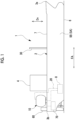
- a ship 1 of the present embodiment includes a hull 2, a superstructure 4, an ammonia storage tank 10, an inert gas supply device 50 (refer to Fig. 2 ), a vent pipe 38 (refer to Fig. 2 ), and a treatment tank 60.
- the ship type of the ship 1 is not limited to a specific type.
- a liquefied gas carrier, a ferry, a RORO ship, a car carrier, a passenger ship, or the like can be exemplified.
- the hull 2 has a pair of broadsides 5A and 5B and a ship bottom 6 that form an outer shell of the hull.
- the broadsides 5A and 5B include a pair of broadside outer plates forming the left and right broadsides.
- the ship bottom 6 includes a ship bottom outer plate that connects the broadsides 5A and 5B.
- the outer shell of the hull 2 is formed in a U shape in a cross section orthogonal to a bow-stern direction FA by the pair of broadsides 5A and 5B and the ship bottom 6.
- the hull 2 further includes an upper deck 7 that is a through deck which is disposed in the uppermost layer.
- the upper deck 7 that is exemplified in the present embodiment is also an exposed deck that is exposed to the outside.
- the superstructure 4 is formed on the upper deck 7.
- An accommodation space and the like are provided in the superstructure 4.
- a cargo space (not shown) for loading cargo is provided in the hull 2 on the bow 3a side with respect to the superstructure 4 in the bow-stern direction FA and below the upper deck 7.
- an internal combustion engine 8 is provided inside the hull 2.
- the internal combustion engine 8 is used as a main engine for propelling the ship 1, a generator for supplying electricity to the ship, and the like.
- the internal combustion engine 8 is operated by using ammonia stored in the ammonia storage tank 10 as fuel.
- the ammonia storage tank 10 stores liquefied ammonia.
- the ammonia storage tank 10 of the present embodiment is provided in the hull 2. A case where the ammonia storage tank 10 is disposed on the upper deck 7 on the stern 3b side with respect to the superstructure 4 in the bow-stern direction FA is exemplified.
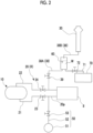
- the ammonia storage tank 10 and the internal combustion engine 8 are connected through a pipe system 20.
- the pipe system 20 forms a circulation path R for ammonia, which communicates with the ammonia storage tank 10.
- the pipe system 20 includes a supply pipe 21, a return pipe 22, and on/off valves 23 and 24.
- the inert gas supply device 50 and a vent post 30 are connected to the pipe system 20.
- Each of the supply pipe 21 and the return pipe 22 connects the ammonia storage tank 10 and the internal combustion engine 8.
- the supply pipe 21 supplies ammonia from the ammonia storage tank 10 to the internal combustion engine 8.
- the return pipe 22 returns surplus ammonia remaining without being used as fuel in the internal combustion engine 8 to the ammonia storage tank 10.
- the on/off valves 23 and 24 are provided in the supply pipe 21 and the return pipe 22.
- the on/off valves 23 and 24 are always in an open state when the internal combustion engine 8 operates.
- the on/off valves 23 and 24 are in a closed state when the internal combustion engine 8 is stopped.
- the flow paths formed inside the supply pipe 21 and the return pipe 22 are blocked by closing the on/off valves 23 and 24.
- the inert gas supply device 50 supplies an inert gas to the circulation path R for ammonia, which communicates with the ammonia storage tank 10.
- the inert gas supply device 50 supplies the inert gas to the pipe system 20 which is the circulation path R.
- the inert gas supply device 50 includes an inert gas supply unit 51, an inert gas supply pipe 52, and an inert gas supply valve 53.
- the inert gas supply unit 51 can supply an inert gas such as nitrogen (for example, an inert gas or the like) to the inert gas supply pipe 52.
- the inert gas supply pipe 52 connects the inert gas supply unit 51 and the pipe system 20.
- the inert gas supply pipe 52 is connected to a purge target region 20p of the pipe system 20.
- the purge target region 20p is the side including the internal combustion engine 8 between the on/off valve 23 of the supply pipe 21 and the on/off valve 24 of the return pipe 22 in the pipe system 20.
- the inert gas supply valve 53 is provided in the inert gas supply pipe 52. As shown in Fig. 3 , the inert gas supply valve 53 is in a closed state in normal times to cut off the supply of the inert gas from the inert gas supply unit 51 to the purge target region 20p of the pipe system 20. In this state, the on/off valves 23 and 24 are in an open state to allow ammonia to be supplied from the ammonia storage tank 10 to the internal combustion engine 8 through the supply pipe 21 and surplus ammonia to be returned from the internal combustion engine 8 to the ammonia storage tank 10.
- the inert gas supply valve 53 is changed from a closed state to an open state.
- the on/off valves 23 and 24 are in a closed state, and the supply pipe 21 and the return pipe 22 are blocked. That is, a state is created in which the supply of ammonia from the ammonia storage tank 10 to the internal combustion engine 8 is stopped.
- the inert gas supply valve 53 is opened, the inert gas is supplied from the inert gas supply unit 51 to the purge target region 20p of the pipe system 20.
- the inert gas supply device 50 supplies the inert gas to the purge target region 20p of the pipe system 20, which is the circulation path R for ammonia, so that so-called purging to replace the ammonia in the purge target region 20p (the circulation path R) with the inert gas is performed.
- the vent pipe 38 leads the ammonia in the circulation path R together with the inert gas that is supplied by the inert gas supply device 50 to the outside.
- One end of the vent pipe 38 is connected to the purge target region 20p as the circulation path R for ammonia, which communicates with the ammonia storage tank 10.
- the other end of the vent pipe 38 is connected to the vent post 30.
- the vent post 30 is provided on the upper deck 7 of the hull 2.
- the vent post 30 extends in an up-down direction Dv on the upper deck 7.
- the vent post 30 has a tubular shape extending in the up-down direction Dv and is open at the top portion thereof.
- the other end of the vent pipe 38 described above is connected to a lower portion of the vent post 30.
- a purge on/off valve 39 is provided in the vent pipe 38.
- the purge on/off valve 39 is in a closed state in normal times to block the flow path in the vent pipe 38.
- the purge on/off valve 39 is changed from a closed state to an open state. That is, the purge on/off valve 39 is opened and closed in conjunction with the inert gas supply valve 53.
- the purge on/off valve 39 enters an open state in a case where the inert gas is supplied from the inert gas supply unit 51 to the purge target region 20p of the pipe system 20 by the inert gas supply device 50.
- the purge on/off valve 39 is in an open state, the ammonia in the purge target region 20p is sent from the purge target region 20p of the pipe system 20 into the vent pipe 38 together with the inert gas.
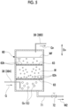
- the treatment tank 60 is disposed on the way from one end of the vent pipe 38 to the other end. More specifically, the treatment tank 60 is disposed between the purge on/off valve 39 and the vent post 30. As shown in Fig. 1 , the treatment tank 60 of the embodiment of the present disclosure is provided on the upper deck 7, for example. The installation position of the treatment tank 60 is not limited at all, and it is sufficient if the treatment tank 60 is installed at an appropriate location on the hull 2.
- the portion of the vent pipe 38 that is provided on the upstream side (the purge on/off valve 39 side) in the gas flow direction in the vent pipe 38 with respect to the treatment tank 60 is referred to as an upstream-side vent pipe 38A.
- the portion of the vent pipe 38 that is provided on the downstream side (the vent post 30 side) in the gas flow direction in the vent pipe 38 with respect to the treatment tank 60 is referred to as a downstream-side vent pipe 38B. That is, the upstream-side vent pipe 38A is connected to the lower portion of the treatment tank 60, and the downstream-side vent pipe 38B is connected to the upper portion of the treatment tank 60.
- water W is stored in the treatment tank 60.
- the inert gas and an ammonia gas (hereinafter sometimes referred to as "ammonia-containing gas G") sent from the purge on/off valve 39 side through the upstream-side vent pipe 38A connected to the lower portion of the treatment tank 60 are introduced into a region below a water surface Wf of the treatment tank 60.
- the upstream-side vent pipe 38A of the present embodiment extends downward within the treatment tank 60. Then, the ammonia-containing gas G is introduced into the lower portion of the treatment tank 60 from the lower end of the upstream-side vent pipe 38A.
- the ammonia-containing gas G introduced from the upstream-side vent pipe 38A forms bubbles Gv, which float upward from below.
- the ammonia-containing gas G comes into contact with the water W in the treatment tank 60. Since ammonia easily reacts with the water W, the ammonia becomes ammonia water due to the reaction with the water W, and easily dissolves in the water.
- the inert gas is difficult to dissolve in the water W, so that the inert gas rises in the state of the bubbles Gv and is released into atmosphere above the water surface Wf in the treatment tank 60.
- a porous member 63 is provided in the treatment tank 60.
- the porous member 63 is provided below the water surface Wf of the water W stored in the treatment tank 60.
- the porous member 63 has, for example, a flat plate shape and is provided along a plane intersecting (orthogonal to) the up-down direction Dv.
- a plurality of (a large number of) holes 63h are formed in the porous member 63.
- perforated metal, wire mesh, or the like can be used for example.
- each hole 63h is set smaller than the size of the initial bubble Gv sent into the water W in the treatment tank 60 from the upstream-side vent pipe 38A.
- each hole 63h is a round hole, it is favorable if the diameter of each hole 63h is smaller than the bubble diameter (for example, the average bubble diameter) of the initial bubbles Gv sent into the water W of the treatment tank 60.
- the bubbles Gv of the ammonia-containing gas G which float upward from below in the water W of the treatment tank 60, pass through the holes 63h of the porous member 63 formed as described above, thereby being made finer.
- the bubbles Gv of the ammonia-containing gas G are made finer, so that the contact area between the bubbles Gv of the ammonia-containing gas G and the water increases. In this way, the ammonia contained in the gas G reacts with the water W in the treatment tank 60 and easily dissolves in the water W.
- a gas Gn that has passed through the water W in the treatment tank 60 from below to above the water surface Wf contains a large amount of inert gas.
- the gas Gn may contain ammonia that does not dissolve in the water W.
- the gas Gn over the water surface Wf of the treatment tank 60 is sent to the vent post 30 through the downstream-side vent pipe 38B.
- the vent post 30 releases the gas Gn introduced from below into the atmosphere through the opening at the top portion.
- a water recovery tank 70 (refer to Fig. 2 ) is connected to the treatment tank 60 through a recovery pipe 71.
- the water recovery tank 70 is provided inside the hull 2.
- a water recovery on/off valve 72 is provided in the recovery pipe 71. When the water recovery on/off valve 72 is opened after the purge treatment is ended, water W2 is discharged from the treatment tank 60 through the recovery pipe 71 and recovered in the water recovery tank 70.
- the stored water W2 may be subjected to treatment to reduce the concentration of ammonia, neutralization treatment, or the like, by using seawater or the like separately taken in from the outside.
- the ammonia in the circulation path R is extruded to the vent pipe 38 together with the inert gas.
- purging in which the ammonia in the circulation path R is replaced with the inert gas, can be performed.
- the ammonia-containing gas Gn extruded to the vent pipe 38 is introduced to below the water surface Wf of the water W stored in the treatment tank 60 from the vent pipe 38.
- the ammonia-containing gas G forms the bubbles Gv in the water W in the treatment tank 60, and the bubbles Gv float upward from below.
- the water W comes into contact with the ammonia-containing gas G. Since ammonia easily reacts with the water W, it becomes ammonia water due to the reaction with the water W and dissolves in the water W. In this way, the content of ammonia in the gas Gn that is led from the vent pipe 38 to the outside through the treatment tank 60 is reduced. In this way, it becomes possible to reduce the amount of ammonia released into the atmosphere.
- the treatment tank 60 includes the porous member 63 having a plurality of holes 63h through which the bubbles Gv of the ammonia-containing gas G pass.
- the ammonia-containing gas G which floats upward from below in the state of the bubbles Gv below the water surface Wf of the water in the treatment tank 60 passes through the holes 63h of the porous member 63, so that the bubbles Gv are made finer according to the size of the hole 63h.
- the bubbles Gv of the ammonia-containing gas G are made finer, so that the contact area between the bubbles Gv of the ammonia-containing gas G and the water increases.
- the ammonia reacts with the water W in the treatment tank 60 and easily dissolves in the water W. In this way, it is possible to more efficiently reduce the amount of ammonia released into the atmosphere.
- the water recovery tank 70 that stores the water W2 which is discharged from the treatment tank 60 is further provided.
- the water W2 in which ammonia is dissolved in the treatment tank 60 can be stored in the water recovery tank 70.
- treatment to dilute the ammonia contained in the recovered water W2, neutralization treatment, or the like can also be performed.
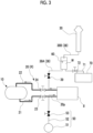
- the treatment tank 60 is provided on the way from one end to the other end of the vent pipe 38, as in the first embodiment.
- the treatment tank 60 stores the water W therein.
- the ammonia-containing gas G which is sent from the purge on/off valve 39 side through the upstream-side vent pipe 38A connected to the lower portion of the treatment tank 60 is introduced to below the water surface Wf of the treatment tank 60.
- the ammonia-containing gas G introduced from the upstream-side vent pipe 38A forms bubbles Gv, which float upward from below.
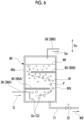
- a partition plate 65 is provided inside the treatment tank 60.
- the partition plate 65 is provided below the water surface Wf of the water W in the treatment tank 60.
- two partition plates 65 are provided with an interval in the up-down direction Dv.
- Each partition plate 65 is formed so as to follow a plane (for example, a horizontal plane) intersecting (orthogonal to) the up-down direction Dv.
- a partition plate 65A on one side is provided on a side surface 60s located on one side in the horizontal direction in the treatment tank 60.
- the partition plate 65A is provided with a gap in the horizontal direction interposed between it and a side surface 60t located on the other side in the horizontal direction in the treatment tank 60.
- a partition plate 65B on the other side is provided on the side surface 60t located on the other side in the horizontal direction in the treatment tank 60.
- the partition plate 65B is provided with a gap in the horizontal direction interposed between it and the side surface 60s located on one side in the horizontal direction in the treatment tank 60.
- the bubbles Gv of the ammonia-containing gas G floating upward from below in the treatment tank 60 hit against the partition plates 65, so that the length of the path F of the flow of the bubble Gv of the ammonia-containing gas G in the treatment tank 60 increases.
- the contact time between the bubbles Gv of the ammonia-containing gas G and the water W increases.
- the ammonia reacts with the water W in the treatment tank 60 and easily dissolves in the water W. In this way, as in the first embodiment, it is possible to more efficiently reduce the amount of ammonia released into the atmosphere.
- dilution water is introduced from the outside through a dilution water introduction system 80C.
- the dilution water introduction system 80C introduces seawater as the dilution water from the outside of the hull 2.
- the dilution water introduction system 80C includes a pump 81 for sucking seawater from the outside of the hull 2, and an on/off valve 82.
- the on/off valve 82 is opened and the pump 81 is operated to introduce seawater and supply it to the treatment tank 60 and the water recovery tank 70.
- the treatment tank 60 is provided with a water injection unit 68C.
- the water injection unit 68C injects water Wk supplied through the dilution water introduction system 80C in the form of a shower downward from above the water surface Wf of the water W in the treatment tank 60.
- the water recovery tank 70 is provided with a water supply unit 78C.
- the water supply unit 78C supplies the water Wk, which is supplied through the dilution water introduction system 80C, downward from above the water W2 stored in the water recovery tank 70.
- the water recovery tank 70 is connected to the treatment tank 60 through the recovery pipe 71, as in the first embodiment.
- a case where the water recovery on/off valve 72 is not provided in the recovery pipe 71 of the second embodiment is exemplified. However, the water recovery on/off valve 72 may be provided in the same manner as in the first embodiment.
- the recovery pipe 71 of the second embodiment is a so-called overflow pipe, and moves surplus water W to the water recovery tank 70 by its own weight when the water surface Wf in the treatment tank 60 reaches a predetermined level or higher.
- a discharge system 90C is connected to the water recovery tank 70.
- the discharge system 90C discharges some of the water W2 stored in the water recovery tank 70.
- the discharge system 90C discharges surplus water W2 from the water recovery tank 70 to the outside as the dilution water is introduced from the outside by the dilution water introduction system 80C.
- the discharge system 90C includes an overflow pipe 91.
- a tip portion 91a of the overflow pipe 91 is open at a lower portion inside the water recovery tank 70.
- the overflow pipe 91 extends upward from the tip portion 91a and has a pipe top portion 91t at a defined height.
- the pipe top portion 91t is a portion disposed at the highest position in the overflow pipe 91.
- the overflow pipe 91 discharges the surplus water W2 when a water surface Wf2 in the water recovery tank 70 reaches a level equal to or higher than the pipe top portion 91t.
- the discharge system 90C further includes a seawater supply unit 99.
- the seawater supply unit 99 supplies seawater taken in from outside to the water W2 that is discharged from the water recovery tank 70 through the overflow pipe 91.
- the seawater supply unit 99 merges, for example, seawater which is sent from a main cooling seawater pump (not shown) or the like, which takes in seawater from the outside of the hull 2 in order to cool various devices and the like provided within the hull 2, with the water in the overflow pipe 91 and sends it to a discharge pipe 93. In this way, the water W2 in the overflow pipe 91 is further diluted.
- An on/off valve 95 is provided in the discharge pipe 93. The on/off valve 95 is opened, so that as necessary, some of the water W2 in the water recovery tank 70 can be diluted with seawater that is supplied from the seawater supply unit 99 and then discharged overboard from the discharge pipe 93.
- the water recovery tank 70 for storing the water W2 that is discharged from the treatment tank 60 is further provided. In this way, the water W2 in which ammonia is dissolved in the treatment tank 60 can be stored in the water recovery tank 70.
- the treatment tank 60 includes the water injection unit 68C.
- ammonia that has not completely dissolved in the water W in the treatment tank 60 is released into atmosphere above the water surface Wf together with the inert gas.
- the water W injected from the water injection unit 68C comes into contact with the ammonia released into atmosphere above the water surface Wf, so that the ammonia recovery efficiency can be improved.
- the water W in which ammonia is dissolved is diluted with the dilution water (the water Wk) introduced from the outside through the dilution water introduction system 80C, so that the ammonia concentration of the water W that is discharged overboard can be lowered.
- the seawater supply unit 99 for supplying seawater taken in from the outside is provided in the discharge system 90C, so that the ammonia concentration of the water W that is discharged overboard from the discharge system 90C can be lowered by the seawater that is supplied from the seawater supply unit 99.
- the water injection unit 68C and the water supply unit 78C are provided. However, only one of the water injection unit 68C and the water supply unit 78C may be provided.
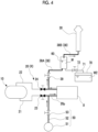
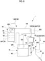
- the ship 1 of the present embodiment includes a circulation system 100.
- the circulation system 100 circulates some of the water W2 stored in the water recovery tank 70 to the treatment tank 60.
- the circulation system 100 includes a pump 101.
- the pump 101 sends the water W2 in the water recovery tank 70 to treatment tank 60.
- a neutralization treatment unit 110 is provided in the circulation system 100.
- the neutralization treatment unit 110 performs neutralization treatment on the water W2 sucked from the water recovery tank 70 by the pump 101.
- the water W subjected to the neutralization treatment in the neutralization treatment unit 110 is supplied to the treatment tank 60 through the circulation system 100.
- neutralization treatment neutralization treatment using dilute sulfuric acid can be exemplified.
- concentration of ammonia after the neutralization treatment may be 20 ppm or less and more preferably less than 10 ppm.
- the circulation system 100 includes a bypass system 120 that bypasses the neutralization treatment unit 110.
- the circulation system 100 includes a switching valve (not shown) that switches the flow of the water W2 between the neutralization treatment unit 110 and the bypass system 120, and can select whether or not to perform the neutralization treatment in the neutralization treatment unit 110.
- the neutralization treatment may be performed through the water W only in a case where the concentration of ammonia in the water W detected by a sensor (not shown) exceeds an upper limit value determined in advance. Further, the neutralization treatment unit 110 may constantly perform neutralization treatment on the water W flowing through the circulation system 100.
- the treatment tank 60 of the ship 1 of the fourth embodiment includes a water injection unit 68D.
- the water injection unit 68D injects the water W in the form of a shower downward from above the water surface Wf of the water W in the treatment tank 60.
- the water injection unit 68D injects the water W (W2) circulated from the water recovery tank 70 through the circulation system 100 into the treatment tank 60.
- the water recovery tank 70 includes a dilution water introduction system 80D.
- the dilution water introduction system 80D supplies the dilution water introduced from the outside into the water recovery tank 70 as water Ws.
- the water recovery tank 70 is provided with a water supply unit 78D.
- the water supply unit 78D supplies the dilution water introduced from the outside through the dilution water introduction system 80D downward from the upper portion of the water recovery tank 70 as the water Ws.
- the dilution water introduction system 80D introduces fresh water from a fresh water tank (not shown) provided in the hull 2 and supplies it as the water Ws from the water supply unit 78D.
- the water W2 in the water recovery tank 70 is diluted with the water Ws, which is fresh water, and an increase in ammonia concentration is suppressed.
- the water W (W2) is circulated between the treatment tank 60 and the water recovery tank 70, and fresh water is used for reasons such as rust prevention.
- a discharge system 90D is connected to the neutralization treatment unit 110.
- the discharge system 90D discharges the surplus water W2, which is generated when the dilution water (water Ws) is introduced from the outside by the dilution water introduction system 80D, from the water recovery tank 70 to the outside.
- the discharge system 90D discharges some of the water W2 stored in the water recovery tank 70 to the outside after the neutralization treatment in the neutralization treatment unit 110.
- the discharge system 90D includes a delivery pipe 92 that delivers the water W2 neutralized in the neutralization treatment unit 110.
- the discharge system 90D further includes the seawater supply unit 99.
- the seawater supply unit 99 supplies the seawater taken in from the outside to water W3 that is discharged from the neutralization treatment unit 110 through the delivery pipe 92.
- the seawater supply unit 99 merges the seawater that is supplied from a main cooling seawater pump (not shown) or the like with the water in the delivery pipe 92 and sends it to the discharge pipe 93. In this way, the water W3 in the delivery pipe 92 is diluted.
- An on/off valve 95 is provided in the discharge pipe 93. The on/off valve 95 is opened, so that as necessary, some of the water W3 discharged from the neutralization treatment unit 110 can be diluted with the seawater that is supplied from the seawater supply unit 99 and then discharged overboard from the discharge pipe 93.
- the water recovery tank 70 for storing the water W2 that is discharged from the treatment tank 60 is further provided. In this way, the water W2 in which ammonia is dissolved in the treatment tank 60 can be stored in the water recovery tank 70.
- the ship 1 includes the circulation system 100. In this way, some of the water W2 recovered from the treatment tank 60 to the water recovery tank 70 is circulated to the treatment tank 60, so that ammonia can be recovered using more water W in an ammonia recovery device as a whole.
- the ship 1 includes the neutralization treatment unit 110.
- neutralization treatment is performed on the ammonia in the water W2 in the water recovery tank 70 by the neutralization treatment unit 110, so that an increase in the ammonia concentration in the water W (W2) is suppressed.
- the water W3 whose ammonia concentration is lowered by the neutralization treatment can be discharged overboard.
- the water W in which ammonia is dissolved is diluted with the dilution water (water Ws) introduced from the outside by the dilution water introduction system 80D, so that an increase in ammonia concentration in the water W (W2) circulating between the water recovery tank 70 and the treatment tank 60 is suppressed. Further, the ammonia concentration in the water W3 discharged overboard can be lowered.
- the treatment tank 60 includes the water injection unit 68D.
- the water W injected from the water injection unit 68D comes into contact with the ammonia released into atmosphere above the water surface Wf, so that the ammonia recovery efficiency is enhanced.
- seawater supply unit 99 is provided in the discharge system 90D, so that the ammonia concentration of the water W which is discharged overboard from the discharge system 90D can be lowered by the seawater which is supplied from the seawater supply unit 99.
- the platelike porous member 63 is provided.
- a member of any shape may be used as long as the bubbles Gv pass through it, so that the bubbles Gv are made finer.
- the porous member for example, a sponge-like porous member or the like having a large number of holes can be adopted.
- the hole 63h is not limited to a circular shape.
- the hole 63h may be an elongated hole, a polygonal hole, a slit-shaped hole, or the like.
- the ammonia in the purge target region 20p is introduced into the treatment tank 60 by the inert gas supply device 50.
- the ammonia may be introduced into the treatment tank 60 from a pipe in another appropriate portion as long as it is the circulation path R for ammonia, which communicates with the ammonia storage tank.
- the internal combustion engine 8 is shown as a device that is driven by the ammonia that is supplied from the ammonia storage tank.
- the use of the internal combustion engine 8 is not limited at all.
- the device is not limited to the internal combustion engine 8, and may be a boiler or the like as long as it is driven by ammonia.
- ammonia storage tank is provided on the stern 3b side with respect to the superstructure 4.
- the ammonia storage tank may be provided on the upper deck 7 on the bow 3a side with respect to the superstructure 4.
- the ammonia storage tank may be provided not only on the upper deck 7 but also inside the hull 2 below the upper deck 7.
- ammonia that is introduced into the treatment tank 60 is not limited to the ammonia that is stored in the ammonia storage tank storing fuel for propelling the ship 1 and may be ammonia that is stored in a tank for cargo that is carried by the ship 1.
- the ammonia in the circulation path R is extruded to the vent pipe 38 together with the inert gas.
- purging in which the ammonia in the circulation path R is replaced with the inert gas, can be performed.
- the ammonia-containing gas Gn extruded to the vent pipe 38 is introduced to below the water surface Wf of the water W stored in the treatment tank 60 from the vent pipe 38.
- the ammonia-containing gas G forms the bubbles Gv in the water W in the treatment tank 60 and floats upward from below. At this time, the water W comes into contact with the ammonia-containing gas G.
- Ammonia easily reacts with the water W2, so that it becomes ammonia water due to the reaction with the water W and dissolves in the water. In this way, the content of ammonia in the gas Gn that is led from the vent pipe 38 to the outside through the treatment tank 60 is reduced. On the other hand, nitrogen is difficult to dissolve in the water W, floats in the state of the bubbles Gv, and is released into atmosphere above the water surface Wf. In this way, it becomes possible to reduce the amount of ammonia released into the atmosphere.
- the treatment tank 60 is provided with the porous member 63 that is provided below the water surface Wf of the water W and has a plurality of holes 63h through which the bubbles Gv of the inert gas and the ammonia which float upward from below in the water W pass.
- the ammonia-containing gas G which floats upward from below in the state of the bubbles Gv below the water surface Wf of the water in the treatment tank 60 passes through the holes 63h of the porous member 63, so that the bubbles Gv are made finer according to the diameter of the hole 63h.
- the bubbles Gv of the ammonia-containing gas G are made finer, so that the contact area between the bubbles Gv of the ammonia-containing gas G and the water increases.
- the ammonia reacts with the water W in the treatment tank 60 and easily dissolves in the water W. In this way, it is possible to more efficiently reduce the amount of ammonia released into the atmosphere.
- the treatment tank 60 is provided with the partition plate 65 that is provided along a plane intersecting the up-down direction Dv below the water surface Wf of the water W.
- the ship 1 of any one of the above (1) to (3) further includes the water recovery tank 70 provided in the hull 2 to store the water W2 that is discharged from the treatment tank 60.
- the water W2 in which ammonia is dissolved in the treatment tank 60 can be stored in the water recovery tank 70.
- treatment to dilute the ammonia contained in the recovered water W2, neutralization treatment, or the like can also be performed.
- the ship 1 of the above (4) further includes the circulation system 100 that circulates some of the water W2 stored in the water recovery tank 70 to the treatment tank 60.
- the treatment tank 60 includes the water injection unit 68C or 68D that injects the water W or Wk downward from above the water surface Wf of the water W.
- ammonia that has not completely dissolved in the water W in the treatment tank 60 is released into atmosphere above the water surface Wf together with the inert gas.
- the water W or Wk injected by the water injection unit 68C or 68D comes into contact with the ammonia released into atmosphere above the water surface Wf, so that the ammonia recovery efficiency in the treatment tank 60 is enhanced.
- the ship 1 of any one of the above (4) to (6) further includes the neutralization treatment unit 110 that performs neutralization treatment on the water W2 in the water recovery tank 70.
- neutralization treatment is performed on the ammonia in the water W2 in the water recovery tank 70 by the neutralization treatment unit 110, so that an increase in ammonia concentration in the water W or W2 is suppressed. Further, in a case where the water W2 is discharged overboard, the water W2 whose ammonia concentration is lowered by the neutralization treatment can be discharged overboard.
- the ship 1 of any one of the above (4) to (7) further includes: the dilution water introduction system 80C or 80D that introduces dilution water from the outside into at least one of the treatment tank 60 and the water recovery tank 70; and the discharge system 90C or 90D that discharges some of the water W2 stored in the water recovery tank 70.
- the water W2 in which the ammonia is dissolved is diluted with the dilution water introduced from the outside by the dilution water introduction systems 80C or 80D, so that the ammonia concentration of the water W2 which is discharged can be lowered.
- the water W2 in the water recovery tank 70 is circulated to the treatment tank 60 by the circulation system 100, an increase in ammonia concentration in the water W (W2) that circulates between the water recovery tank 70 and the treatment tank 60 is suppressed.
- the ship 1 of the above (8) further includes the seawater supply unit 99 that supplies seawater taken in from the outside to the discharge system 90C or 90D.
- the ammonia concentration of the water W2 that is discharged overboard from the discharge system 90C or 90D can be lowered by the seawater that is supplied from the seawater supply unit 99.
Landscapes
- Engineering & Computer Science (AREA)
- Mechanical Engineering (AREA)
- Chemical & Material Sciences (AREA)
- General Engineering & Computer Science (AREA)
- Combustion & Propulsion (AREA)
- Ocean & Marine Engineering (AREA)
- Chemical Kinetics & Catalysis (AREA)
- General Chemical & Material Sciences (AREA)
- Oil, Petroleum & Natural Gas (AREA)
- Thermal Sciences (AREA)
- Physics & Mathematics (AREA)
- Environmental & Geological Engineering (AREA)
- Analytical Chemistry (AREA)
- Gas Separation By Absorption (AREA)
- Public Health (AREA)
- Toxicology (AREA)
- General Health & Medical Sciences (AREA)
- Health & Medical Sciences (AREA)
- Filling Or Discharging Of Gas Storage Vessels (AREA)
- Physical Water Treatments (AREA)
Claims (9)
- Schiff (1) umfassend:einen Schiffsrumpf (2); undeinen Ammoniak-Lagertank (10), der in der Lage ist, Ammoniak zu lagern;eine Inertgasversorgungsvorrichtung (50), die ein Inertgas in einen Umlaufsweg (R) für das Ammoniak versorgt, der mit dem Ammoniak-Lagertank (10) in Kommunikation steht;eine Entlüftungsleitung (38), die das Ammoniak in den Umlaufsweg (R) zusammen mit dem von der Inertgasversorgungsvorrichtung (50) versorgten Inertgas nach außen führt; undeinen Behandlungstank (60), der in der Mitte der Entlüftungsleitung (38) vorgesehen ist und in dem Wasser (W) gelagert wird, und in den das Inertgas und das Ammoniak aus der Entlüftungsleitung (38) unterhalb einer Wasseroberfläche (Wf) des Wassers (W) eingeleitet werden.
- Schiff (1) nach Anspruch 1, wobei der Behandlungstank (60) mit einem porösen Element (63) versehen ist, das unterhalb der Wasseroberfläche (Wf) des Wassers (W) vorgesehen ist und eine Vielzahl von Löchern (63h) aufweist, durch die Blasen (Gv) des Inertgases und des Ammoniaks, die in dem Wasser (W) von unten nach oben schwimmen, hindurchtreten.
- Schiff (1) nach Anspruch 1 oder 2, wobei der Behandlungstank (60) mit einer Trennplatte (65) versehen ist, die entlang einer Ebene vorgesehen ist, die durch eine Nach Oben und Unten-Richtung (Dv) unterhalb der Wasseroberfläche (Wf) des Wassers (W) kreuzt.
- Schiff (1) nach einem der Ansprüche 1 bis 3, ferner umfassend:
einen Wasserrückgewinnungstank (70), der in dem Rumpf (2) vorgesehen ist, um Wasser (W2) zu lagern, das aus dem Behandlungstank (60) abgelassen wird. - Schiff (1) nach Anspruch 4, ferner umfassend:
ein Umlaufsystem (100), das einen Teil des in dem Wasserrückgewinnungstank (70) gelagerten Wassers (W2) zum Behandlungstank (60) umlaufen lässt. - Schiff (1) nach Anspruch 4 oder 5, wobei der Behandlungstank (60) eine Wasserspritzeinheit (68C, 68D) umfasst, die Wasser (W, Wk) von oberhalb der Wasseroberfläche (Wf) des Wassers (W) nach unten spritzt.
- Schiff (1) nach einem der Ansprüche 4 bis 6, ferner umfassend:
eine Neutralisationsbehandlungseinheit (110), die eine Neutralisationsbehandlung des Wassers (W2) in dem Wasserrückgewinnungstank (70) durchführt. - Schiff (1) nach einem der Ansprüche 4 bis 7, ferner umfassend:ein Verdünnungswassereinleitungssystem (80C, 80D), das Verdünnungswasser von außen in den Behandlungstank (60) und/oder in den Wasserrückgewinnungstank (70) einleitet; undein Ablasssystem (90C, 90D), das einen Teil des in dem Wasserrückgewinnungstank (70) gelagerten Wassers ablässt.
- Schiff (1) nach Anspruch 8, ferner umfassend:
eine Seewasserversorgungseinheit (99), die von außen angesaugtes Seewasser in das Abflusssystem (90C, 90D) versorgt.
Applications Claiming Priority (3)
| Application Number | Priority Date | Filing Date | Title |
|---|---|---|---|
| JP2020141419 | 2020-08-25 | ||
| JP2020209288A JP6934555B1 (ja) | 2020-08-25 | 2020-12-17 | 船舶 |
| PCT/JP2021/031139 WO2022045184A1 (ja) | 2020-08-25 | 2021-08-25 | 船舶 |
Publications (4)
| Publication Number | Publication Date |
|---|---|
| EP4184052A1 EP4184052A1 (de) | 2023-05-24 |
| EP4184052A4 EP4184052A4 (de) | 2024-01-17 |
| EP4184052B1 true EP4184052B1 (de) | 2025-01-29 |
| EP4184052C0 EP4184052C0 (de) | 2025-01-29 |
Family
ID=77657833
Family Applications (1)
| Application Number | Title | Priority Date | Filing Date |
|---|---|---|---|
| EP21861607.6A Active EP4184052B1 (de) | 2020-08-25 | 2021-08-25 | Schiff |
Country Status (5)
| Country | Link |
|---|---|
| EP (1) | EP4184052B1 (de) |
| JP (1) | JP6934555B1 (de) |
| KR (1) | KR102873217B1 (de) |
| CN (1) | CN115867741A (de) |
| WO (1) | WO2022045184A1 (de) |
Families Citing this family (23)
| Publication number | Priority date | Publication date | Assignee | Title |
|---|---|---|---|---|
| KR102584156B1 (ko) * | 2021-09-16 | 2023-10-05 | 삼성중공업 주식회사 | 선박의 연료공급시스템 |
| KR102552858B1 (ko) * | 2021-09-17 | 2023-07-10 | 대한조선 주식회사 | 암모니아 가스 처리 시스템 및 이를 포함하는 선박 |
| KR102584155B1 (ko) * | 2021-09-23 | 2023-10-04 | 삼성중공업 주식회사 | 선박의 암모니아처리시스템 |
| JP7623927B2 (ja) * | 2021-11-04 | 2025-01-29 | 株式会社神戸製鋼所 | 吸収装置、ガス処理装置、吸収方法及びガス処理方法 |
| KR102632393B1 (ko) * | 2021-12-02 | 2024-02-01 | 한화오션 주식회사 | 선박의 암모니아 배출 시스템 |
| WO2023101523A1 (ko) * | 2021-12-03 | 2023-06-08 | 현대중공업 주식회사 | 암모니아 처리 시스템 및 이를 포함하는 선박 |
| JP2023092231A (ja) * | 2021-12-21 | 2023-07-03 | 三菱造船株式会社 | 浮体及び浮体の不活性ガス排出方法 |
| KR20240150510A (ko) * | 2022-03-25 | 2024-10-15 | 가부시키가이샤 아이에이치아이 | 연소 시스템 |
| KR102758690B1 (ko) * | 2022-05-20 | 2025-01-23 | 에이치디한국조선해양 주식회사 | 연료 처리 시스템 및 이를 포함하는 선박 |
| KR102701288B1 (ko) * | 2022-05-20 | 2024-08-30 | 삼성중공업 주식회사 | 암모니아 처리 시스템 |
| JP7590805B2 (ja) * | 2022-06-24 | 2024-11-27 | 株式会社三井E&S | アンモニア除害装置およびアンモニア除害方法 |
| JP2024010807A (ja) | 2022-07-13 | 2024-01-25 | 三菱造船株式会社 | 浮体 |
| JP2024013263A (ja) * | 2022-07-20 | 2024-02-01 | 三菱造船株式会社 | 浮体 |
| KR102821192B1 (ko) * | 2022-07-20 | 2025-06-17 | 한화오션 주식회사 | 선박용 엔진의 암모니아 배출 시스템 |
| DE102022118252B4 (de) | 2022-07-21 | 2025-01-02 | Man Energy Solutions Se | Brennkraftmaschine, die als Kraftstoff zumindest anteilig Ammoniak verbrennt, und Verfahren zum Betreiben derselben |
| JP2024042171A (ja) * | 2022-09-15 | 2024-03-28 | 三菱造船株式会社 | アンモニア処理システム、浮体 |
| JP2024064598A (ja) * | 2022-10-28 | 2024-05-14 | 三菱重工業株式会社 | アンモニア除害システム、浮体、及びアンモニア除害方法 |
| JP7784988B2 (ja) * | 2022-12-20 | 2025-12-12 | 三菱重工業株式会社 | アンモニア除害システム、浮体、及びアンモニア除害方法 |
| JP7466747B1 (ja) | 2023-08-07 | 2024-04-12 | 株式会社三井E&S | アンモニアガスの処理装置及び処理方法 |
| WO2025084467A1 (ko) * | 2023-10-19 | 2025-04-24 | 에이치디한국조선해양 주식회사 | 연료 처리 시스템 및 이를 포함하는 선박 |
| EP4545778A1 (de) | 2023-10-27 | 2025-04-30 | Alfa Laval Corporate AB | Ammoniakabschwächungssystem für ammoniakkraftstoffversorgungssystem und ammoniakmotor und verfahren zum betrieb des abschwächungssystems |
| JP7553730B1 (ja) | 2024-01-30 | 2024-09-18 | 三菱化工機株式会社 | 潤滑油清浄システム及び潤滑油清浄方法 |
| JP7621534B1 (ja) | 2024-02-29 | 2025-01-24 | 三菱化工機株式会社 | アンモニア含有廃液の中和処理システム及びアンモニア含有廃液の中和処理方法 |
Citations (10)
| Publication number | Priority date | Publication date | Assignee | Title |
|---|---|---|---|---|
| JPH04310212A (ja) | 1991-04-04 | 1992-11-02 | Ishikawajima Harima Heavy Ind Co Ltd | アンモニア吸収装置 |
| JPH07206426A (ja) | 1994-01-14 | 1995-08-08 | Babcock Hitachi Kk | アンモニア希釈槽 |
| JP2001023913A (ja) | 1999-07-09 | 2001-01-26 | Hitachi Kokusai Electric Inc | 反応管着脱用台車および半導体製造装置 |
| JP2006334591A (ja) | 2006-07-24 | 2006-12-14 | Kurita Engineering Co Ltd | アンモニアタンク内残留ガスの処理方法 |
| JP2013011332A (ja) | 2011-06-30 | 2013-01-17 | Mitsubishi Heavy Ind Ltd | 燃料積込装置 |
| KR20170057714A (ko) | 2015-11-17 | 2017-05-25 | 현대중공업 주식회사 | 선박 |
| KR20180041923A (ko) | 2016-10-17 | 2018-04-25 | 현대중공업 주식회사 | 가스 처리 시스템 및 선박 |
| JP2019014335A (ja) | 2017-07-05 | 2019-01-31 | 川崎重工業株式会社 | 船舶 |
| JP2019178840A (ja) | 2018-03-30 | 2019-10-17 | 株式会社Ihi | 燃焼装置、ガスタービン及び発電装置 |
| CN110694437A (zh) | 2019-11-14 | 2020-01-17 | 中冶南方都市环保工程技术股份有限公司 | 一种氨水罐超压排放氨气的自动吸收再利用装置 |
Family Cites Families (18)
| Publication number | Priority date | Publication date | Assignee | Title |
|---|---|---|---|---|
| JPH1119456A (ja) * | 1997-07-04 | 1999-01-26 | Babcock Hitachi Kk | アンモニアガス希釈槽 |
| JP2002028431A (ja) * | 2000-07-12 | 2002-01-29 | Asahi Yukinaka | アンモニア希釈装置 |
| JP3550356B2 (ja) * | 2000-12-08 | 2004-08-04 | 株式会社新来島どっく | 液状貨物輸送船のステンレス鋼製カーゴタンクの防食方法および防食装置 |
| JP2003020221A (ja) * | 2001-07-05 | 2003-01-24 | Nkk Corp | アンモニア水製造装置 |
| JP4614062B2 (ja) * | 2004-10-06 | 2011-01-19 | 株式会社日立プラントテクノロジー | 空気中のアンモニア処理方法及び装置 |
| TWI403156B (zh) | 2008-08-08 | 2013-07-21 | 尼康股份有限公司 | Carrying information machines, photographic devices, and information acquisition systems |
| KR101117677B1 (ko) * | 2009-06-22 | 2012-03-08 | 주식회사 엔케이 | 선박용 배기가스의 탈황 탈질 처리장치 |
| KR102138662B1 (ko) * | 2013-12-17 | 2020-07-28 | 재단법인 포항산업과학연구원 | 이산화탄소 회수장치 |
| JP6499485B2 (ja) * | 2015-03-24 | 2019-04-10 | クボタ環境サ−ビス株式会社 | 脱臭処理装置、脱臭処理システム、及び脱臭処理方法 |
| KR20160120046A (ko) * | 2015-04-07 | 2016-10-17 | 대우조선해양 주식회사 | 선체 내에 고압가스 분사엔진을 탑재한 선박 |
| KR101762599B1 (ko) * | 2015-10-29 | 2017-07-28 | 삼성중공업 주식회사 | 연료전지를 사용한 방한처리 및 보조전원 시스템을 구비한 극지 운항 선박 |
| KR101826685B1 (ko) * | 2016-04-07 | 2018-02-07 | 대우조선해양 주식회사 | 액체화물 증발 저감 시스템 및 방법 |
| KR102114525B1 (ko) * | 2016-12-28 | 2020-05-22 | 현대중공업 주식회사 | 가스연료 추진 컨테이너 운반선 |
| KR101873780B1 (ko) * | 2017-05-26 | 2018-07-04 | 삼성중공업 주식회사 | 선박의 연료공급시스템 |
| CN208003715U (zh) * | 2018-02-28 | 2018-10-26 | 莫文亮 | 一种氨尾气处理回收系统 |
| JP2020020928A (ja) | 2018-07-31 | 2020-02-06 | 株式会社日立製作所 | 通信装置および通信プログラム |
| KR102111503B1 (ko) * | 2019-05-14 | 2020-05-15 | 대우조선해양 주식회사 | 친환경 선박의 연료공급시스템 |
| JP7377094B2 (ja) * | 2019-12-19 | 2023-11-09 | 三菱造船株式会社 | 船舶 |
-
2020
- 2020-12-17 JP JP2020209288A patent/JP6934555B1/ja active Active
-
2021
- 2021-08-25 KR KR1020237004289A patent/KR102873217B1/ko active Active
- 2021-08-25 WO PCT/JP2021/031139 patent/WO2022045184A1/ja not_active Ceased
- 2021-08-25 CN CN202180050453.3A patent/CN115867741A/zh active Pending
- 2021-08-25 EP EP21861607.6A patent/EP4184052B1/de active Active
Patent Citations (10)
| Publication number | Priority date | Publication date | Assignee | Title |
|---|---|---|---|---|
| JPH04310212A (ja) | 1991-04-04 | 1992-11-02 | Ishikawajima Harima Heavy Ind Co Ltd | アンモニア吸収装置 |
| JPH07206426A (ja) | 1994-01-14 | 1995-08-08 | Babcock Hitachi Kk | アンモニア希釈槽 |
| JP2001023913A (ja) | 1999-07-09 | 2001-01-26 | Hitachi Kokusai Electric Inc | 反応管着脱用台車および半導体製造装置 |
| JP2006334591A (ja) | 2006-07-24 | 2006-12-14 | Kurita Engineering Co Ltd | アンモニアタンク内残留ガスの処理方法 |
| JP2013011332A (ja) | 2011-06-30 | 2013-01-17 | Mitsubishi Heavy Ind Ltd | 燃料積込装置 |
| KR20170057714A (ko) | 2015-11-17 | 2017-05-25 | 현대중공업 주식회사 | 선박 |
| KR20180041923A (ko) | 2016-10-17 | 2018-04-25 | 현대중공업 주식회사 | 가스 처리 시스템 및 선박 |
| JP2019014335A (ja) | 2017-07-05 | 2019-01-31 | 川崎重工業株式会社 | 船舶 |
| JP2019178840A (ja) | 2018-03-30 | 2019-10-17 | 株式会社Ihi | 燃焼装置、ガスタービン及び発電装置 |
| CN110694437A (zh) | 2019-11-14 | 2020-01-17 | 中冶南方都市环保工程技术股份有限公司 | 一种氨水罐超压排放氨气的自动吸收再利用装置 |
Non-Patent Citations (1)
| Title |
|---|
| "Water seal in the vent outlet for ammonia systems on an ammonia fueled engine", RESEARCH DISCLOSURE JOURNAL, QUESTEL, vol. 675, no. 38, 1 July 2020 (2020-07-01), pages 966, XP007148475, ISSN: 0374-4353 |
Also Published As
| Publication number | Publication date |
|---|---|
| EP4184052C0 (de) | 2025-01-29 |
| EP4184052A1 (de) | 2023-05-24 |
| KR102873217B1 (ko) | 2025-10-17 |
| CN115867741A (zh) | 2023-03-28 |
| KR20230035108A (ko) | 2023-03-10 |
| JP2022037849A (ja) | 2022-03-09 |
| EP4184052A4 (de) | 2024-01-17 |
| JP6934555B1 (ja) | 2021-09-15 |
| WO2022045184A1 (ja) | 2022-03-03 |
Similar Documents
| Publication | Publication Date | Title |
|---|---|---|
| EP4184052B1 (de) | Schiff | |
| EP4335741A1 (de) | Schiff | |
| KR102852857B1 (ko) | 선박 | |
| EP4299431A1 (de) | Gefäss | |
| US20100139547A1 (en) | Piping structure for oil tanker | |
| KR102150302B1 (ko) | 선박 | |
| EP4467440A1 (de) | Schiff | |
| CN116476990A (zh) | 船舶 | |
| EP4592174A1 (de) | Ammoniakentgiftungssystem, schwimmkörper und ammoniakentgiftungsverfahren | |
| JP2022156549A (ja) | 船舶 | |
| JP4491003B2 (ja) | 液体貨物船のバラストタンクのイナートガス注入・置換設備およびイナートガス注入・置換方法 | |
| EP4566695A1 (de) | Ammoniakbehandlungssystem, schwimmkörper | |
| KR102850481B1 (ko) | 자동차 운반선 | |
| US20250100655A1 (en) | Ship | |
| KR102915499B1 (ko) | 선박 | |
| KR20240021956A (ko) | 부체 | |
| JP2024037338A (ja) | 浮体、浮体のアンモニア処理方法 | |
| KR20260005764A (ko) | 선박 | |
| KR20250025008A (ko) | 액화 이산화탄소 격납 설비 및 선박 |
Legal Events
| Date | Code | Title | Description |
|---|---|---|---|
| STAA | Information on the status of an ep patent application or granted ep patent |
Free format text: STATUS: THE INTERNATIONAL PUBLICATION HAS BEEN MADE |
|
| PUAI | Public reference made under article 153(3) epc to a published international application that has entered the european phase |
Free format text: ORIGINAL CODE: 0009012 |
|
| STAA | Information on the status of an ep patent application or granted ep patent |
Free format text: STATUS: REQUEST FOR EXAMINATION WAS MADE |
|
| 17P | Request for examination filed |
Effective date: 20230220 |
|
| AK | Designated contracting states |
Kind code of ref document: A1 Designated state(s): AL AT BE BG CH CY CZ DE DK EE ES FI FR GB GR HR HU IE IS IT LI LT LU LV MC MK MT NL NO PL PT RO RS SE SI SK SM TR |
|
| TPAC | Observations filed by third parties |
Free format text: ORIGINAL CODE: EPIDOSNTIPA |
|
| DAV | Request for validation of the european patent (deleted) | ||
| DAX | Request for extension of the european patent (deleted) | ||
| A4 | Supplementary search report drawn up and despatched |
Effective date: 20231214 |
|
| RIC1 | Information provided on ipc code assigned before grant |
Ipc: B63H 21/38 20060101ALI20231208BHEP Ipc: C02F 1/66 20230101ALI20231208BHEP Ipc: B01D 53/14 20060101ALI20231208BHEP Ipc: F17C 13/00 20060101AFI20231208BHEP |
|
| GRAP | Despatch of communication of intention to grant a patent |
Free format text: ORIGINAL CODE: EPIDOSNIGR1 |
|
| STAA | Information on the status of an ep patent application or granted ep patent |
Free format text: STATUS: GRANT OF PATENT IS INTENDED |
|
| INTG | Intention to grant announced |
Effective date: 20240902 |
|
| GRAS | Grant fee paid |
Free format text: ORIGINAL CODE: EPIDOSNIGR3 |
|
| GRAA | (expected) grant |
Free format text: ORIGINAL CODE: 0009210 |
|
| STAA | Information on the status of an ep patent application or granted ep patent |
Free format text: STATUS: THE PATENT HAS BEEN GRANTED |
|
| RAP3 | Party data changed (applicant data changed or rights of an application transferred) |
Owner name: MITSUBISHI SHIPBUILDING CO., LTD. |
|
| AK | Designated contracting states |
Kind code of ref document: B1 Designated state(s): AL AT BE BG CH CY CZ DE DK EE ES FI FR GB GR HR HU IE IS IT LI LT LU LV MC MK MT NL NO PL PT RO RS SE SI SK SM TR |
|
| REG | Reference to a national code |
Ref country code: GB Ref legal event code: FG4D |
|
| REG | Reference to a national code |
Ref country code: CH Ref legal event code: EP |
|
| REG | Reference to a national code |
Ref country code: DE Ref legal event code: R096 Ref document number: 602021025661 Country of ref document: DE |
|
| REG | Reference to a national code |
Ref country code: IE Ref legal event code: FG4D |
|
| U01 | Request for unitary effect filed |
Effective date: 20250129 |
|
| U07 | Unitary effect registered |
Designated state(s): AT BE BG DE DK EE FI FR IT LT LU LV MT NL PT RO SE SI Effective date: 20250205 |
|
| PG25 | Lapsed in a contracting state [announced via postgrant information from national office to epo] |
Ref country code: RS Free format text: LAPSE BECAUSE OF FAILURE TO SUBMIT A TRANSLATION OF THE DESCRIPTION OR TO PAY THE FEE WITHIN THE PRESCRIBED TIME-LIMIT Effective date: 20250429 |
|
| PG25 | Lapsed in a contracting state [announced via postgrant information from national office to epo] |
Ref country code: PL Free format text: LAPSE BECAUSE OF FAILURE TO SUBMIT A TRANSLATION OF THE DESCRIPTION OR TO PAY THE FEE WITHIN THE PRESCRIBED TIME-LIMIT Effective date: 20250129 |
|
| PG25 | Lapsed in a contracting state [announced via postgrant information from national office to epo] |
Ref country code: ES Free format text: LAPSE BECAUSE OF FAILURE TO SUBMIT A TRANSLATION OF THE DESCRIPTION OR TO PAY THE FEE WITHIN THE PRESCRIBED TIME-LIMIT Effective date: 20250129 |
|
| PG25 | Lapsed in a contracting state [announced via postgrant information from national office to epo] |
Ref country code: IS Free format text: LAPSE BECAUSE OF FAILURE TO SUBMIT A TRANSLATION OF THE DESCRIPTION OR TO PAY THE FEE WITHIN THE PRESCRIBED TIME-LIMIT Effective date: 20250529 Ref country code: NO Free format text: LAPSE BECAUSE OF FAILURE TO SUBMIT A TRANSLATION OF THE DESCRIPTION OR TO PAY THE FEE WITHIN THE PRESCRIBED TIME-LIMIT Effective date: 20250429 |
|
| PG25 | Lapsed in a contracting state [announced via postgrant information from national office to epo] |
Ref country code: HR Free format text: LAPSE BECAUSE OF FAILURE TO SUBMIT A TRANSLATION OF THE DESCRIPTION OR TO PAY THE FEE WITHIN THE PRESCRIBED TIME-LIMIT Effective date: 20250129 |
|
| PG25 | Lapsed in a contracting state [announced via postgrant information from national office to epo] |
Ref country code: GR Free format text: LAPSE BECAUSE OF FAILURE TO SUBMIT A TRANSLATION OF THE DESCRIPTION OR TO PAY THE FEE WITHIN THE PRESCRIBED TIME-LIMIT Effective date: 20250430 |
|
| U20 | Renewal fee for the european patent with unitary effect paid |
Year of fee payment: 5 Effective date: 20250709 |
|
| PG25 | Lapsed in a contracting state [announced via postgrant information from national office to epo] |
Ref country code: SM Free format text: LAPSE BECAUSE OF FAILURE TO SUBMIT A TRANSLATION OF THE DESCRIPTION OR TO PAY THE FEE WITHIN THE PRESCRIBED TIME-LIMIT Effective date: 20250129 |
|
| PG25 | Lapsed in a contracting state [announced via postgrant information from national office to epo] |
Ref country code: CZ Free format text: LAPSE BECAUSE OF FAILURE TO SUBMIT A TRANSLATION OF THE DESCRIPTION OR TO PAY THE FEE WITHIN THE PRESCRIBED TIME-LIMIT Effective date: 20250129 |
|
| PG25 | Lapsed in a contracting state [announced via postgrant information from national office to epo] |
Ref country code: SK Free format text: LAPSE BECAUSE OF FAILURE TO SUBMIT A TRANSLATION OF THE DESCRIPTION OR TO PAY THE FEE WITHIN THE PRESCRIBED TIME-LIMIT Effective date: 20250129 |
|
| PLBI | Opposition filed |
Free format text: ORIGINAL CODE: 0009260 |
|
| 26 | Opposition filed |
Opponent name: EVERLLENCE, FILIAL AF EVERLLENCE SE, TYSKLAND Effective date: 20251027 |
|
| PLAX | Notice of opposition and request to file observation + time limit sent |
Free format text: ORIGINAL CODE: EPIDOSNOBS2 |