EP4177197A1 - Garnreiniger sowie schneideinrichtung für einen garnreiniger - Google Patents
Garnreiniger sowie schneideinrichtung für einen garnreiniger Download PDFInfo
- Publication number
- EP4177197A1 EP4177197A1 EP21206556.9A EP21206556A EP4177197A1 EP 4177197 A1 EP4177197 A1 EP 4177197A1 EP 21206556 A EP21206556 A EP 21206556A EP 4177197 A1 EP4177197 A1 EP 4177197A1
- Authority
- EP
- European Patent Office
- Prior art keywords
- housing
- cutting
- cutting means
- cutting device
- means carrier
- Prior art date
- Legal status (The legal status is an assumption and is not a legal conclusion. Google has not performed a legal analysis and makes no representation as to the accuracy of the status listed.)
- Pending
Links
Images
Classifications
-
- D—TEXTILES; PAPER
- D03—WEAVING
- D03J—AUXILIARY WEAVING APPARATUS; WEAVERS' TOOLS; SHUTTLES
- D03J1/00—Auxiliary apparatus combined with or associated with looms
- D03J1/02—Auxiliary apparatus combined with or associated with looms for treating warp, e.g. cleaning, moistening
-
- D—TEXTILES; PAPER
- D02—YARNS; MECHANICAL FINISHING OF YARNS OR ROPES; WARPING OR BEAMING
- D02J—FINISHING OR DRESSING OF FILAMENTS, YARNS, THREADS, CORDS, ROPES OR THE LIKE
- D02J3/00—Modifying the surface
- D02J3/02—Modifying the surface by abrading, scraping, scuffing, cutting, or nicking
-
- B—PERFORMING OPERATIONS; TRANSPORTING
- B65—CONVEYING; PACKING; STORING; HANDLING THIN OR FILAMENTARY MATERIAL
- B65H—HANDLING THIN OR FILAMENTARY MATERIAL, e.g. SHEETS, WEBS, CABLES
- B65H54/00—Winding, coiling, or depositing filamentary material
- B65H54/70—Other constructional features of yarn-winding machines
- B65H54/71—Arrangements for severing filamentary materials
-
- D—TEXTILES; PAPER
- D03—WEAVING
- D03J—AUXILIARY WEAVING APPARATUS; WEAVERS' TOOLS; SHUTTLES
- D03J1/00—Auxiliary apparatus combined with or associated with looms
- D03J1/04—Auxiliary apparatus combined with or associated with looms for treating weft
-
- D—TEXTILES; PAPER
- D04—BRAIDING; LACE-MAKING; KNITTING; TRIMMINGS; NON-WOVEN FABRICS
- D04B—KNITTING
- D04B35/00—Details of, or auxiliary devices incorporated in, knitting machines, not otherwise provided for
-
- D—TEXTILES; PAPER
- D06—TREATMENT OF TEXTILES OR THE LIKE; LAUNDERING; FLEXIBLE MATERIALS NOT OTHERWISE PROVIDED FOR
- D06H—MARKING, INSPECTING, SEAMING OR SEVERING TEXTILE MATERIALS
- D06H7/00—Apparatus or processes for cutting, or otherwise severing, specially adapted for the cutting, or otherwise severing, of textile materials
- D06H7/02—Apparatus or processes for cutting, or otherwise severing, specially adapted for the cutting, or otherwise severing, of textile materials transversely
-
- B—PERFORMING OPERATIONS; TRANSPORTING
- B65—CONVEYING; PACKING; STORING; HANDLING THIN OR FILAMENTARY MATERIAL
- B65H—HANDLING THIN OR FILAMENTARY MATERIAL, e.g. SHEETS, WEBS, CABLES
- B65H2701/00—Handled material; Storage means
- B65H2701/30—Handled filamentary material
- B65H2701/31—Textiles threads or artificial strands of filaments
Definitions
- the aim is usually to achieve the highest possible level of uniformity in the finished yarn within narrow tolerances and a yarn without visible defects, such as intolerable thick or thin places.
- so-called yarn clearers are used at the individual work stations of a textile machine, which, for example, continuously monitor the diameter of the yarn with a suitable measuring head. If an intolerable error is detected due to exceeding or falling below the limit values known as cleaning limits, the error is cut out of the yarn by means of the cutting device of the yarn clearer cutting device located in the housing body, the yarn ends are connected again and the production process is continued.
- Known cutting devices for yarn cleaners have, for example, an electromagnetically acting cutting means drive, with a cutting means carrier, on which a cutting blade is arranged, being adjusted between a rest position and a cutting position by means of the cutting means drive in the manner of a chisel, with a between the Cutting means carrier and an anvil arranged yarn is severed in the cutting position.
- the cutting device is arranged within a housing body and is connected via a drive element, which extends through a first housing opening, to the cutting means carrier arranged outside the housing interior, so that the cutting means carrier can be brought into engagement with the yarn via the drive element by means of the cutting means drive in an adjustable manner is.
- the cutting device is preferably arranged on the housing body in such a way that when the yarn clearer is installed, the cutting device is preferably located at the front end of the housing body - in relation to the yarn running direction - so that it is ensured that, due to the rotational inertia of a spool receiving the yarn, a thread guide area of the yarn clearer is thread-free after the cut.
- arranging the cutting device in the entry area of the housing body, in relation to the direction of travel of the yarn has the disadvantage that this area is subject to a higher concentration of loose fibers due to the system.
- this fiber loading can result in fibers arranging themselves in the area of the first housing opening and from there getting into the interior of the housing, where they lead to increased friction in the area of the cutting device and thus to a low cutting force and in the result in faulty cutting processes.
- the invention is based on the object of providing a yarn clearer with a cutting device and a cutting device which ensure reliable separation of the yarn if necessary.
- the invention solves the problem by a cutting device with the features of claim 1 and by a yarn clearer with the features of claim 10.
- Advantageous developments of the cutting device are specified in the dependent claims 2 to 9.
- the housing body of the cutting device has a housing base body and a housing cover at least partially covering the housing base body.
- the housing cover and the housing body jointly delimit a housing interior space, within which a cutting means drive of a cutting device is arranged.
- the housing body has a first housing opening which is connected to the interior of the housing and through which a drive element extends, which connects the cutting-means drive to the cutting-means carrier, see above that the cutting means carrier can be adjusted between a rest position and a cutting position by means of the cutting means drive, the drive element being arranged adjustably in the first housing opening for this purpose.
- the housing body has a bearing section in the area in front of the first housing opening, i.e. outside the housing interior, for adjustably receiving the cutting means carrier and the bearing section has a second housing opening opposite the first housing opening in the direction of adjustment of the cutting means carrier between the rest position and the cutting position.
- the second housing opening is designed in such a way that its edge, which runs coaxially to the direction of adjustment of the cutting means carrier, rests against the cutting means carrier, but ensures an adjustment movement of the cutting means carrier relative to the housing body between the cutting position and the rest position.
- the housing body is designed in the region of the second housing opening for the flush arrangement of an end face of the cutting means carrier in the rest position.
- the preferably flat end face of the cutting means carrier, on which the cutting blade is arranged runs in the rest position in one plane with the surface of the housing body surrounding the second housing opening.
- the cutting means carrier is displaced relative to the housing body from the flush arrangement into the cutting position in which the end face protrudes at least in sections from the housing body or, in an alternative preferred embodiment, is arranged at a distance therefrom.
- the flush arrangement of the end face in the rest position ensures in a particularly reliable manner that in the rest position there are no unwanted deposits of free fibers in the area of the cutting means carrier on the housing body, which can occur in the event of an adjustment of the cutting means carrier, in particular when moving back out of the cutting position could be transported into the rest position in the direction of the interior of the housing. Due to the flush arrangement in the rest position, a deposit of free fibers in the area of the second housing opening can be prevented in a particularly reliable manner, since this avoids edges that promote an accumulation of free fibers.
- the first housing opening bears against the drive element with an opening edge running perpendicularly to the adjustment direction of the drive element.
- This configuration of the invention in which the opening edge of the first housing opening also has a sealing effect in addition to a guiding function of the drive element in the housing body, ensures in a supplementary manner that any free fibers that have penetrated into the bearing section via the second housing opening cannot continue into the interior of the housing are transported, in which the cutting means drive driving the cutting means carrier via the drive element is arranged. Contamination of the housing interior is additionally prevented by the advantageously provided configuration of the first housing opening.
- the design of the bearing section in the area between the first and second The housing opening, in which the cutting means carrier is arranged so that it can be adjusted between the rest position and the cutting position, can in principle be freely selected.
- the bearing section delimited by the housing cover and housing body has at least one wall section arranged at a distance from the cutting means carrier to form an expansion area.
- the bearing section does not bear against the cutting means carrier all the way round, but rather that at least one of the wall sections provided by the housing base body and housing cover—viewed transversely to the adjustment direction of the cutting means carrier between the rest position and the cutting position—is arranged at a distance from the cutting means carrier .
- the expansion area thus represents a free area between the first and second housing opening, which has a larger free cross section than the free area of the second housing opening, so that under certain circumstances free fibers penetrating through the first housing opening into the storage section due to the widening housing section and the the resulting pressure difference does not reach the second housing opening despite a suction effect occurring in the region of the second housing opening during a return movement of the cutting means carrier from the cutting position into the rest position. Due to its larger cross section, the expansion area reduces any negative pressure that may prevail under certain circumstances.
- the cutting means carrier has a projection which protrudes into the expansion area and can be adjusted in this area between the rest position and the cutting position. According to this embodiment of the invention, it is provided that the cutting means carrier has a projection, e.g.
- the housing body has a ventilation opening for ventilating the housing interior, which is preferably arranged on a side of the housing body that is different from the first housing opening, particularly preferably on an underside of the housing body or on a side of the housing body opposite the first housing opening is.
- the housing body basically has at any point, but preferably at a - as defined above side of the housing body - based on the installation position of the cutting device, i. H. on a side of the housing body oriented counter to the thread running direction, a ventilation opening which connects the surroundings of the housing body to the interior of the housing.
- the inner walls of the bearing section and/or the outer surfaces of the cutting-means carrier and/or the outer surfaces of the drive element have a polished surface.
- a polished surface is understood to mean an average roughness value Ra of the surfaces in the range from 0.01 to 0.2.
- a corresponding surface quality also prevents free fibers from accumulating on the individual surfaces and getting into the bearing section and/or the interior of the housing in the event of an adjustment of the cutting-means carrier.
- the polished surfaces encourage the free fibers to slide off.
- the design of the housing body and the housing cover to form the Housing body is basically freely selectable.
- the housing base body and the housing cover can each be designed as half-shell-shaped bodies, which together delimit the housing interior and the storage section.
- the housing base body has a flat housing base body inner wall and the housing cover has a housing cover edge that stands up circumferentially on the housing base body inner wall and a housing cover base body that adjoins the housing cover edge.
- the housing base body provides a substantially flat inner wall of the housing base body, on which the half-shell-shaped housing cover rests with a surrounding housing cover edge, so that the housing cover base body opposite the inner wall of the housing base body is arranged at a distance from the flat surface of the housing base body.
- This embodiment of the invention represents a particularly simple possibility for producing the housing body, it being possible for the inner wall of the housing base body to be provided by further housing bodies of the yarn clearer.
- this configuration of the invention offers the possibility of providing the bearing section provided according to the invention and other advantageous configurations of the housing body simply by a corresponding configuration of the housing cover.
- the housing cover to form the bearing section has housing cover webs that protrude from the housing cover base body in the direction of the housing base body and stand up on the flat inner wall of the housing base body.
- the invention also achieves the object by means of a yarn clearer for a work station of a textile machine with a cutting device for cleaning out defects from a yarn, which has a cutting device according to the invention or a further development described above.
- a yarn clearer according to the invention is characterized by its high reliability when carrying out the cutting processes, with disruptions due to contamination of the yarn clearer in the area of the cutting device being able to be avoided particularly effectively.
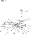
- figure 1 shows a perspective view of an embodiment of a cutting device 1 with a cutting means drive 6, a drive element 21 and a cutting means carrier 5, on which a cutting blade 4 having a cutting edge 20 is arranged.
- the cutting means carrier 5 is by means of the cutting means drive 6 from the figure 1
- the rest position shown can be adjusted into a cutting position, not shown here, in which the cutting edge 20 comes into engagement with a stop face 3 of an anvil 2 arranged on an anvil carrier 7 and cuts through a yarn, not shown here, located in between.
- the anvil 2 rests with an underside 17 on an upper side 19 of a fastening section 18 of the anvil carrier 7 and is screwed to it via a fastening screw 9 which extends through a through bore 12 in the anvil 2 into a threaded bore 8 on the fastening section 18.
- the fastening screw 9 can be screwed into a housing base that is not shown.
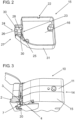
- FIG 3 shows a perspective view of a yarn clearer 10 with a housing body 14 formed from a housing cover 15 and a housing base body 11.
- the housing base body 11, which is part of the yarn clearer 10 provides a flat housing base body inner wall to form the housing body 14, which is covered by the housing cover 15 and thus delimits a housing interior 16 from the environment of the yarn clearer 10 .
- the housing cover 15 stands, as in figure 2 shown, doing so with a housing cover edge 31 and housing webs 30 on the inner wall of the housing base body.
- the cutting device 1 is arranged in sections within the housing body 14, with the cutting blade 4 on the cutting means carrier 5 protruding from the housing body 14 in the illustrated rest position in the direction of the stop surface 3 of the anvil 2.
- a yarn (not shown here) runs in the area between the stop surface 3 of the anvil 2 and the cutting edge 20 of the cutting blade 4. If a yarn cut is to be carried out, the cutting blade 4 is shifted from the rest position shown to the cutting position in which the cutting edge 20 rests against the stop surface 3 of the anvil 2 and cuts through the yarn located in between.
- the cutting means drive 6 of the cutting device 1 is arranged inside the housing interior 16 of the housing cover 15 .
- the cutting-means drive 6 is connected via the drive element 21 to the cutting-means carrier 5, which can be adjusted between the rest position and the cutting position within a bearing section 27 of the housing cover.
- the drive element 21 protrudes through a first housing opening 23 of the housing cover 15, so that when the cutting-means drive 6 is activated, the cutting-means carrier 5 is adjusted within the bearing section 27 between the rest position and the cutting position, with the cutting-means carrier 5 within a second housing opening 24 up to the cutting position is adjusted, in which the cutting edge 20 of the cutting blade 4 spaced from the outer wall of the housing cover 15 rests on the stop surface 3 of the anvil 2.
- the second housing opening 24 and the first housing opening 23 of the housing cover 15, which are arranged one behind the other in the adjustment direction, are designed in such a way that they bear against the drive element 21 and the cutting-means carrier 5 with a peripheral opening edge 26, so that any free fibers that may be present in the area in front of the second housing opening 24 are not enter the storage section 27.
- the storage section 27 also has a wall section 25 arranged at a distance from an upper side 29 of the cutting means carrier 5, whereby an expansion area 28 is formed in which any free fibers that may penetrate are collected due to the existing pressure difference and are not passed on in the direction of the first housing opening 23.
- the cutting means carrier 5 has a web-like projection 13 which extends across the width of the expansion area 28 - viewed transversely to the direction of adjustment - and protrudes into it, so that any free fibers arranged in the expansion area 28 are moved or pushed out of the second housing opening 24 by the projection 13 when the cutting means carrier 5 is adjusted from the rest position into the cutting position can become.
- the housing cover 15 On the underside of the housing, the housing cover 15 has a ventilation opening 22, through which the housing interior 16 is fluidically connected to the environment, so that when the drive element 21 is adjusted from the rest position to the cutting position, air from the area surrounding the housing cover 15 flows into the housing interior 16 can and counteracts the formation of negative pressure.
- the anvil carrier 7 protrudes from the housing body 14 and together with the anvil 2 forms a stop surface 3 opposite the cutting edge 20 of the cutting blade 4 , the yarn being guided between the housing cover 15 and the anvil 2 during operation of the yarn clearer 10 .
Landscapes
- Engineering & Computer Science (AREA)
- Textile Engineering (AREA)
- Treatment Of Fiber Materials (AREA)
- Filamentary Materials, Packages, And Safety Devices Therefor (AREA)
Priority Applications (4)
| Application Number | Priority Date | Filing Date | Title |
|---|---|---|---|
| EP21206556.9A EP4177197A1 (de) | 2021-11-04 | 2021-11-04 | Garnreiniger sowie schneideinrichtung für einen garnreiniger |
| JP2022176097A JP2023070139A (ja) | 2021-11-04 | 2022-11-02 | 糸クリヤラおよび糸クリヤラ用の切断機構 |
| CN202211368175.9A CN116065294B (zh) | 2021-11-04 | 2022-11-03 | 清纱器以及用于清纱器的切割装置 |
| US17/981,157 US11920264B2 (en) | 2021-11-04 | 2022-11-04 | Yarn clearer and cutting device for a yarn clearer |
Applications Claiming Priority (1)
| Application Number | Priority Date | Filing Date | Title |
|---|---|---|---|
| EP21206556.9A EP4177197A1 (de) | 2021-11-04 | 2021-11-04 | Garnreiniger sowie schneideinrichtung für einen garnreiniger |
Publications (1)
| Publication Number | Publication Date |
|---|---|
| EP4177197A1 true EP4177197A1 (de) | 2023-05-10 |
Family
ID=78528767
Family Applications (1)
| Application Number | Title | Priority Date | Filing Date |
|---|---|---|---|
| EP21206556.9A Pending EP4177197A1 (de) | 2021-11-04 | 2021-11-04 | Garnreiniger sowie schneideinrichtung für einen garnreiniger |
Country Status (4)
| Country | Link |
|---|---|
| US (1) | US11920264B2 (enExample) |
| EP (1) | EP4177197A1 (enExample) |
| JP (1) | JP2023070139A (enExample) |
| CN (1) | CN116065294B (enExample) |
Families Citing this family (1)
| Publication number | Priority date | Publication date | Assignee | Title |
|---|---|---|---|---|
| US12129585B2 (en) * | 2021-02-05 | 2024-10-29 | Nikhil Gupta | Thread conditioner and cutter |
Citations (2)
| Publication number | Priority date | Publication date | Assignee | Title |
|---|---|---|---|---|
| DE2405458A1 (de) * | 1973-07-17 | 1975-02-06 | Amf Inc | Vorrichtung zum durchschneiden eines faden- oder garnstranges |
| EP0253934A1 (en) * | 1986-07-25 | 1988-01-27 | Toray Industries, Inc. | Slub eliminator |
Family Cites Families (19)
| Publication number | Priority date | Publication date | Assignee | Title |
|---|---|---|---|---|
| US2654938A (en) * | 1949-03-17 | 1953-10-13 | Kennedy Robert John | Textile yarn clearer |
| US2624933A (en) * | 1951-04-26 | 1953-01-13 | Kingsboro Silk Mills Inc | Yarn cleaner |
| US2860704A (en) * | 1956-01-11 | 1958-11-18 | United States Steel Corp | Automatic shear for cutting strip |
| US3175290A (en) * | 1962-08-22 | 1965-03-30 | Du Pont | Yarn handling apparatus |
| GB1094272A (en) * | 1964-08-28 | 1967-12-06 | Zellweger Uster Ag | Improvements relating to apparatus for retaining yarns in yarn cleaners |
| US3624720A (en) * | 1970-04-27 | 1971-11-30 | Breeze Corp | Cable cutter |
| CH562672A5 (enExample) * | 1973-08-14 | 1975-06-13 | Apag Apparatebau Ag | |
| CH568134A5 (enExample) * | 1974-02-20 | 1975-10-31 | Zellweger Uster Ag | |
| GB2133732A (en) * | 1983-01-11 | 1984-08-01 | Glencryan Design Ltd | Fabric cutting device and apparatus |
| US5150640A (en) * | 1989-12-28 | 1992-09-29 | E. I. Du Pont De Nemours And Company | High-speed cutter for yarns |
| US5211709A (en) * | 1991-10-09 | 1993-05-18 | Mht, Inc. | Stop motion device for strand processing machine |
| US5839342A (en) * | 1995-06-29 | 1998-11-24 | E. I. Du Pont De Nemours And Company | Yarn cutter |
| DE102009033377A1 (de) * | 2009-07-16 | 2011-01-20 | Oerlikon Textile Gmbh & Co. Kg | Verfahren und Vorrichtung zum Betreiben einer Arbeitsstelle einer Kreuzspulen herstellenden Textilmaschine |
| IT1402740B1 (it) * | 2010-10-19 | 2013-09-18 | Btsr Int Spa | Dispositivo di taglio di un filo tessile durante la sua alimentazione ad un elemento operatore |
| CN202717913U (zh) * | 2010-10-19 | 2013-02-06 | 乌斯特技术股份公司 | 电子清纱器测量头 |
| CN202450211U (zh) * | 2010-10-19 | 2012-09-26 | 乌斯特技术股份公司 | 清纱器测量头 |
| IT1402874B1 (it) * | 2010-11-19 | 2013-09-27 | Btsr Int Spa | Dispositivo di alimentazione di un filo ad una macchina tessile con organo di taglio del filo |
| ITMI20110430A1 (it) * | 2011-03-18 | 2012-09-19 | Santoni & C Spa | Piatto di macchina circolare per maglieria o per calzetteria del tipo con cilindro e piatto con dispositivo di taglio dei fili |
| CN208594364U (zh) * | 2018-07-16 | 2019-03-12 | 荆州市奥达纺织有限公司 | 一种喷气织机成品切边装置 |
-
2021
- 2021-11-04 EP EP21206556.9A patent/EP4177197A1/de active Pending
-
2022
- 2022-11-02 JP JP2022176097A patent/JP2023070139A/ja active Pending
- 2022-11-03 CN CN202211368175.9A patent/CN116065294B/zh active Active
- 2022-11-04 US US17/981,157 patent/US11920264B2/en active Active
Patent Citations (2)
| Publication number | Priority date | Publication date | Assignee | Title |
|---|---|---|---|---|
| DE2405458A1 (de) * | 1973-07-17 | 1975-02-06 | Amf Inc | Vorrichtung zum durchschneiden eines faden- oder garnstranges |
| EP0253934A1 (en) * | 1986-07-25 | 1988-01-27 | Toray Industries, Inc. | Slub eliminator |
Also Published As
| Publication number | Publication date |
|---|---|
| CN116065294A (zh) | 2023-05-05 |
| US11920264B2 (en) | 2024-03-05 |
| US20230134474A1 (en) | 2023-05-04 |
| JP2023070139A (ja) | 2023-05-18 |
| CN116065294B (zh) | 2024-11-29 |
Similar Documents
| Publication | Publication Date | Title |
|---|---|---|
| DE2231578B2 (de) | Vorrichtung zur Reinigung von Fasern an Offenend-Spinnaggregaten | |
| DE19836065A1 (de) | Filterkammer für eine Textilmaschine | |
| DE19855571A1 (de) | Vorrichtung an einer Spinnereimaschine zum Herstellen eines Faserverbandes, z.B. aus Baumwolle, Chemiefasern | |
| EP4177197A1 (de) | Garnreiniger sowie schneideinrichtung für einen garnreiniger | |
| WO2013174573A1 (de) | Dichtleistensystem | |
| DE3524151C2 (enExample) | ||
| DE102015116540A1 (de) | Reinigungsvorrichtung und eine reinigungsvorrichtung umfassendes system | |
| DE3942044C2 (enExample) | ||
| DE2129260C3 (de) | Raklierrolle | |
| DE19501186A1 (de) | Bogenabfühlschuh, Dickenabtastkopf und Dickenmeßsystem | |
| EP3622807A1 (de) | Vorrichtung zum entfernen von blättern und blüten von pflanzen | |
| DE69303714T2 (de) | Vorrichtung zur ununterbrochenen überwachung der nadeln einer strickmaschine während ihres betriebs | |
| DE10024913A1 (de) | Schneidmaschine für laibförmige Produkte | |
| CH677941A5 (enExample) | ||
| DE3520080A1 (de) | Kerbeinrichtung | |
| DE69513894T2 (de) | Aufnahmeeinrichtung für stabförmige Gegenstände | |
| DE102010017904A1 (de) | Koordinatenmessgerät mit Gegengewicht für einen Messschlitten | |
| EP0463128B1 (de) | Vorrichtung zur photoelektrischen überwachung eines laufenden fadens | |
| DE102021214879A1 (de) | Abdeckvorrichtung zur abdeckung einer schiene eines längseinstellers, längseinsteller für einen fahrzeugsitz, sowie fahrzeugsitz | |
| DE2141872C3 (de) | Zigarettenherstellungsmaschine | |
| DE3331195A1 (de) | Vorrichtung zum oe-friktionsspinnen | |
| EP4177200A1 (de) | Fadenführungselement sowie garnreiniger für eine arbeitsstelle einer textilmaschine mit einem fadenführungselement | |
| DE3342481A1 (de) | Oe-friktionsspinnmaschine | |
| CH631676A5 (de) | Fadenfuehrung an einem spulengatter. | |
| CH671981A5 (enExample) |
Legal Events
| Date | Code | Title | Description |
|---|---|---|---|
| PUAI | Public reference made under article 153(3) epc to a published international application that has entered the european phase |
Free format text: ORIGINAL CODE: 0009012 |
|
| STAA | Information on the status of an ep patent application or granted ep patent |
Free format text: STATUS: THE APPLICATION HAS BEEN PUBLISHED |
|
| AK | Designated contracting states |
Kind code of ref document: A1 Designated state(s): AL AT BE BG CH CY CZ DE DK EE ES FI FR GB GR HR HU IE IS IT LI LT LU LV MC MK MT NL NO PL PT RO RS SE SI SK SM TR |
|
| STAA | Information on the status of an ep patent application or granted ep patent |
Free format text: STATUS: REQUEST FOR EXAMINATION WAS MADE |
|
| 17P | Request for examination filed |
Effective date: 20231110 |
|
| RBV | Designated contracting states (corrected) |
Designated state(s): AL AT BE BG CH CY CZ DE DK EE ES FI FR GB GR HR HU IE IS IT LI LT LU LV MC MK MT NL NO PL PT RO RS SE SI SK SM TR |
|
| GRAP | Despatch of communication of intention to grant a patent |
Free format text: ORIGINAL CODE: EPIDOSNIGR1 |
|
| STAA | Information on the status of an ep patent application or granted ep patent |
Free format text: STATUS: GRANT OF PATENT IS INTENDED |
|
| RIC1 | Information provided on ipc code assigned before grant |
Ipc: B65H 54/71 20060101AFI20251003BHEP |
|
| INTG | Intention to grant announced |
Effective date: 20251024 |