EP4167367B1 - Battery module having bent trap part, and battery pack comprising same - Google Patents
Battery module having bent trap part, and battery pack comprising same Download PDFInfo
- Publication number
- EP4167367B1 EP4167367B1 EP22825172.4A EP22825172A EP4167367B1 EP 4167367 B1 EP4167367 B1 EP 4167367B1 EP 22825172 A EP22825172 A EP 22825172A EP 4167367 B1 EP4167367 B1 EP 4167367B1
- Authority
- EP
- European Patent Office
- Prior art keywords
- battery module
- battery
- circulation channel
- air
- trap portion
- Prior art date
- Legal status (The legal status is an assumption and is not a legal conclusion. Google has not performed a legal analysis and makes no representation as to the accuracy of the status listed.)
- Active
Links
Images
Classifications
-
- H—ELECTRICITY
- H01—ELECTRIC ELEMENTS
- H01M—PROCESSES OR MEANS, e.g. BATTERIES, FOR THE DIRECT CONVERSION OF CHEMICAL ENERGY INTO ELECTRICAL ENERGY
- H01M50/00—Constructional details or processes of manufacture of the non-active parts of electrochemical cells other than fuel cells, e.g. hybrid cells
- H01M50/30—Arrangements for facilitating escape of gases
-
- H—ELECTRICITY
- H01—ELECTRIC ELEMENTS
- H01M—PROCESSES OR MEANS, e.g. BATTERIES, FOR THE DIRECT CONVERSION OF CHEMICAL ENERGY INTO ELECTRICAL ENERGY
- H01M10/00—Secondary cells; Manufacture thereof
- H01M10/60—Heating or cooling; Temperature control
- H01M10/61—Types of temperature control
- H01M10/613—Cooling or keeping cold
-
- H—ELECTRICITY
- H01—ELECTRIC ELEMENTS
- H01M—PROCESSES OR MEANS, e.g. BATTERIES, FOR THE DIRECT CONVERSION OF CHEMICAL ENERGY INTO ELECTRICAL ENERGY
- H01M10/00—Secondary cells; Manufacture thereof
- H01M10/60—Heating or cooling; Temperature control
- H01M10/62—Heating or cooling; Temperature control specially adapted for specific applications
- H01M10/625—Vehicles
-
- H—ELECTRICITY
- H01—ELECTRIC ELEMENTS
- H01M—PROCESSES OR MEANS, e.g. BATTERIES, FOR THE DIRECT CONVERSION OF CHEMICAL ENERGY INTO ELECTRICAL ENERGY
- H01M10/00—Secondary cells; Manufacture thereof
- H01M10/60—Heating or cooling; Temperature control
- H01M10/64—Heating or cooling; Temperature control characterised by the shape of the cells
- H01M10/647—Prismatic or flat cells, e.g. pouch cells
-
- H—ELECTRICITY
- H01—ELECTRIC ELEMENTS
- H01M—PROCESSES OR MEANS, e.g. BATTERIES, FOR THE DIRECT CONVERSION OF CHEMICAL ENERGY INTO ELECTRICAL ENERGY
- H01M10/00—Secondary cells; Manufacture thereof
- H01M10/60—Heating or cooling; Temperature control
- H01M10/65—Means for temperature control structurally associated with the cells
- H01M10/655—Solid structures for heat exchange or heat conduction
- H01M10/6553—Terminals or leads
-
- H—ELECTRICITY
- H01—ELECTRIC ELEMENTS
- H01M—PROCESSES OR MEANS, e.g. BATTERIES, FOR THE DIRECT CONVERSION OF CHEMICAL ENERGY INTO ELECTRICAL ENERGY
- H01M10/00—Secondary cells; Manufacture thereof
- H01M10/60—Heating or cooling; Temperature control
- H01M10/65—Means for temperature control structurally associated with the cells
- H01M10/655—Solid structures for heat exchange or heat conduction
- H01M10/6556—Solid parts with flow channel passages or pipes for heat exchange
-
- H—ELECTRICITY
- H01—ELECTRIC ELEMENTS
- H01M—PROCESSES OR MEANS, e.g. BATTERIES, FOR THE DIRECT CONVERSION OF CHEMICAL ENERGY INTO ELECTRICAL ENERGY
- H01M10/00—Secondary cells; Manufacture thereof
- H01M10/60—Heating or cooling; Temperature control
- H01M10/65—Means for temperature control structurally associated with the cells
- H01M10/656—Means for temperature control structurally associated with the cells characterised by the type of heat-exchange fluid
- H01M10/6561—Gases
- H01M10/6562—Gases with free flow by convection only
-
- H—ELECTRICITY
- H01—ELECTRIC ELEMENTS
- H01M—PROCESSES OR MEANS, e.g. BATTERIES, FOR THE DIRECT CONVERSION OF CHEMICAL ENERGY INTO ELECTRICAL ENERGY
- H01M10/00—Secondary cells; Manufacture thereof
- H01M10/60—Heating or cooling; Temperature control
- H01M10/65—Means for temperature control structurally associated with the cells
- H01M10/656—Means for temperature control structurally associated with the cells characterised by the type of heat-exchange fluid
- H01M10/6561—Gases
- H01M10/6566—Means within the gas flow to guide the flow around one or more cells, e.g. manifolds, baffles or other barriers
-
- H—ELECTRICITY
- H01—ELECTRIC ELEMENTS
- H01M—PROCESSES OR MEANS, e.g. BATTERIES, FOR THE DIRECT CONVERSION OF CHEMICAL ENERGY INTO ELECTRICAL ENERGY
- H01M50/00—Constructional details or processes of manufacture of the non-active parts of electrochemical cells other than fuel cells, e.g. hybrid cells
- H01M50/20—Mountings; Secondary casings or frames; Racks, modules or packs; Suspension devices; Shock absorbers; Transport or carrying devices; Holders
- H01M50/204—Racks, modules or packs for multiple batteries or multiple cells
- H01M50/207—Racks, modules or packs for multiple batteries or multiple cells characterised by their shape
- H01M50/209—Racks, modules or packs for multiple batteries or multiple cells characterised by their shape adapted for prismatic or rectangular cells
-
- H—ELECTRICITY
- H01—ELECTRIC ELEMENTS
- H01M—PROCESSES OR MEANS, e.g. BATTERIES, FOR THE DIRECT CONVERSION OF CHEMICAL ENERGY INTO ELECTRICAL ENERGY
- H01M50/00—Constructional details or processes of manufacture of the non-active parts of electrochemical cells other than fuel cells, e.g. hybrid cells
- H01M50/20—Mountings; Secondary casings or frames; Racks, modules or packs; Suspension devices; Shock absorbers; Transport or carrying devices; Holders
- H01M50/204—Racks, modules or packs for multiple batteries or multiple cells
- H01M50/207—Racks, modules or packs for multiple batteries or multiple cells characterised by their shape
- H01M50/211—Racks, modules or packs for multiple batteries or multiple cells characterised by their shape adapted for pouch cells
-
- H—ELECTRICITY
- H01—ELECTRIC ELEMENTS
- H01M—PROCESSES OR MEANS, e.g. BATTERIES, FOR THE DIRECT CONVERSION OF CHEMICAL ENERGY INTO ELECTRICAL ENERGY
- H01M50/00—Constructional details or processes of manufacture of the non-active parts of electrochemical cells other than fuel cells, e.g. hybrid cells
- H01M50/30—Arrangements for facilitating escape of gases
- H01M50/35—Gas exhaust passages comprising elongated, tortuous or labyrinth-shaped exhaust passages
-
- H—ELECTRICITY
- H01—ELECTRIC ELEMENTS
- H01M—PROCESSES OR MEANS, e.g. BATTERIES, FOR THE DIRECT CONVERSION OF CHEMICAL ENERGY INTO ELECTRICAL ENERGY
- H01M50/00—Constructional details or processes of manufacture of the non-active parts of electrochemical cells other than fuel cells, e.g. hybrid cells
- H01M50/30—Arrangements for facilitating escape of gases
- H01M50/383—Flame arresting or ignition-preventing means
-
- H—ELECTRICITY
- H01—ELECTRIC ELEMENTS
- H01M—PROCESSES OR MEANS, e.g. BATTERIES, FOR THE DIRECT CONVERSION OF CHEMICAL ENERGY INTO ELECTRICAL ENERGY
- H01M50/00—Constructional details or processes of manufacture of the non-active parts of electrochemical cells other than fuel cells, e.g. hybrid cells
- H01M50/30—Arrangements for facilitating escape of gases
- H01M50/394—Gas-pervious parts or elements
-
- H—ELECTRICITY
- H01—ELECTRIC ELEMENTS
- H01M—PROCESSES OR MEANS, e.g. BATTERIES, FOR THE DIRECT CONVERSION OF CHEMICAL ENERGY INTO ELECTRICAL ENERGY
- H01M50/00—Constructional details or processes of manufacture of the non-active parts of electrochemical cells other than fuel cells, e.g. hybrid cells
- H01M50/50—Current conducting connections for cells or batteries
- H01M50/502—Interconnectors for connecting terminals of adjacent batteries; Interconnectors for connecting cells outside a battery casing
- H01M50/503—Interconnectors for connecting terminals of adjacent batteries; Interconnectors for connecting cells outside a battery casing characterised by the shape of the interconnectors
-
- H—ELECTRICITY
- H01—ELECTRIC ELEMENTS
- H01M—PROCESSES OR MEANS, e.g. BATTERIES, FOR THE DIRECT CONVERSION OF CHEMICAL ENERGY INTO ELECTRICAL ENERGY
- H01M50/00—Constructional details or processes of manufacture of the non-active parts of electrochemical cells other than fuel cells, e.g. hybrid cells
- H01M50/50—Current conducting connections for cells or batteries
- H01M50/502—Interconnectors for connecting terminals of adjacent batteries; Interconnectors for connecting cells outside a battery casing
- H01M50/505—Interconnectors for connecting terminals of adjacent batteries; Interconnectors for connecting cells outside a battery casing comprising a single busbar
-
- H—ELECTRICITY
- H01—ELECTRIC ELEMENTS
- H01M—PROCESSES OR MEANS, e.g. BATTERIES, FOR THE DIRECT CONVERSION OF CHEMICAL ENERGY INTO ELECTRICAL ENERGY
- H01M2200/00—Safety devices for primary or secondary batteries
-
- H—ELECTRICITY
- H01—ELECTRIC ELEMENTS
- H01M—PROCESSES OR MEANS, e.g. BATTERIES, FOR THE DIRECT CONVERSION OF CHEMICAL ENERGY INTO ELECTRICAL ENERGY
- H01M2220/00—Batteries for particular applications
- H01M2220/20—Batteries in motive systems, e.g. vehicle, ship, plane
-
- Y—GENERAL TAGGING OF NEW TECHNOLOGICAL DEVELOPMENTS; GENERAL TAGGING OF CROSS-SECTIONAL TECHNOLOGIES SPANNING OVER SEVERAL SECTIONS OF THE IPC; TECHNICAL SUBJECTS COVERED BY FORMER USPC CROSS-REFERENCE ART COLLECTIONS [XRACs] AND DIGESTS
- Y02—TECHNOLOGIES OR APPLICATIONS FOR MITIGATION OR ADAPTATION AGAINST CLIMATE CHANGE
- Y02E—REDUCTION OF GREENHOUSE GAS [GHG] EMISSIONS, RELATED TO ENERGY GENERATION, TRANSMISSION OR DISTRIBUTION
- Y02E60/00—Enabling technologies; Technologies with a potential or indirect contribution to GHG emissions mitigation
- Y02E60/10—Energy storage using batteries
Definitions
- the present invention relates to a battery module having a bent trap portion and a battery pack including the same, and more particularly to a battery module having a bent trap portion capable of preventing high-temperature byproducts from being discharged to the outside when thermal runaway occurs in the battery module, whereby it is possible to inhibit secondary damage, and a battery pack including the same.
- the secondary batteries which are capable of being charged and discharged, are intimately used in daily life.
- the secondary batteries are used in mobile devices, electric vehicles, and hybrid electric vehicles.
- the secondary battery When the secondary battery is used in a device that requires large capacity and high output, such as an electric vehicle, the secondary battery is used in the form of a battery module or a battery pack in which a plurality of battery cells is arranged.
- thermal runaway may occur in the battery cells received in the battery module due to overheating, and therefore it is necessary to cool the battery cells in the battery module.
- Thermal runaway and fire outbreak occurring in one battery cell are transferred to battery cells adjacent thereto, whereby high-temperature gas and byproducts are generated.
- fire may break out in a battery pack or a device in which the battery module is mounted while the high-temperature byproducts are discharged from the battery module, whereby secondary damage may occur.
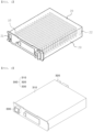
- FIG. 1 is a perspective view of a conventional battery module.
- the conventional battery module includes a plurality of stacked battery cells 10 and a module case 20 configured to receive the plurality of battery cells 10, and the module case 20 is provided with an air inlet 21, an air outlet 22, and an air circulation channel 23 configured to circulate air introduced into the module case in order to cool the battery cells 10 using the air.
- the battery cells 10 are cooled using the air, whereby an increase in temperature is inhibited.
- cooling is limited, whereby thermal runaway may occur.
- high-temperature byproducts and venting gas may be generated due to the thermal runaway.
- the venting gas is discharged through the air inlet 21 and the air outlet 22, the high-temperature byproducts may also be discharged, whereby secondary fire outbreak may occur in a battery pack or a device in which the battery module is mounted.
- Patent Document 1 Korean Patent Application Publication No. 2020-0110081 EP 3 890 056 A1 relates to a battery module and a battery pack including the same, and more particularly, to a battery module for preventing heat diffusion.
- KR 2017 0069003 A relates to a battery module in which when a battery cell ignites, flame or sparks are not discharged to the outside of the module and only smoke is discharged to the outside of the module.
- the present invention has been made in view of the above problems, and it is an object of the present invention to provide a battery module having a bent trap portion capable of preventing high-temperature byproducts generated due to thermal runaway in the battery module from being discharged to the outside and a battery pack including the same.
- a battery module having a bent trap portion includes a plurality of battery cells (100), a busbar (200) configured to electrically connect the plurality of battery cells (100) to each other, and a module case (300) configured to receive the plurality of battery cells (100) and the busbar (200), wherein the module case (300) includes a receiving portion (310) configured to define a predetermined space, a first trap portion (320) configured to introduce air, a second trap portion (330) configured to discharge air, and an air flow channel portion (340) configured to allow the introduced air to move therealong.
- the first trap portion (320) may include a first pocket portion (321) depressed outwardly define a predetermined space and a first air circulation channel (322) bent in a direction toward a side surface of the first pocket portion (321).
- the second trap portion (330) may include a partition wall (331) bent by a predetermined angle so as to define a predetermined space and a second air circulation channel (332) formed in an "S" shape by the partition wall (331) .
- the first air circulation channel (322) may have a gradually increasing width from an inside to an outside thereof.
- the second trap portion (330) may include a second pocket portion (333) depressed outwardly to define a predetermined space and a second air circulation channel (332) bent in a direction toward a side surface of the second pocket portion (333).
- the first air circulation channel (322) may have a gradually increasing width from an inside to an outside thereof.
- the second air circulation channel (333) may have a gradually increasing width from an inside to an outside thereof.
- the first trap portion (320) may be formed at a corner part of one side of the receiving portion (310).
- the second trap portion (330) may be formed at a corner part of the receiving portion (310) located in line with the first trap portion (320).
- the present invention provides a battery pack including the battery module.
- a battery module having a bent trap portion according to the present invention and a battery pack including the same have an advantage in that it is possible to prevent high-temperature byproducts generated due to thermal runaway from being discharged from the battery module, whereby it is possible to inhibit secondary damage due to the byproducts.
- the battery module having the bent trap portion according to the present invention and the battery pack including the same have an advantage in that it is possible to discharge venting gas to the outside while preventing the high-temperature byproducts from being discharged to the outside, whereby it is possible to prevent damage to the battery module due to swelling thereof, and therefore it is possible to improve safety of the battery module.
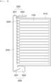
- FIG. 2 is a perspective view of a battery module according to a first preferred embodiment of the present invention
- FIG. 3 is a sectional view of the battery module shown in FIG. 2 taken in a horizontal direction.
- the battery module according to the first preferred embodiment of the present invention includes battery cells 100, a busbar 200, and a module case 300.
- each of the battery cells 100 includes a cell assembly, a cell case configured to receive the cell assembly, and a pair of leads.
- the cell assembly may be a jelly-roll type cell assembly, which is configured to have a structure in which a long sheet type positive electrode and a long sheet type negative electrode are wound in the state in which a separator is interposed therebetween, a stacked type cell assembly constituted by unit cells, each of which is configured to have a structure in which a rectangular positive electrode and a rectangular negative electrode are stacked in the state in which a separator is interposed therebetween, a stacked and folded type cell assembly, which is configured to have a structure in which unit cells are wound using a long separation film, or a laminated and stacked type cell assembly, which is configured to have a structure in which unit cells are stacked in the state in which a separator is interposed therebetween and are then attached to each other.
- the present invention is not limited thereto.
- the cell assembly is mounted in the cell case, and the cell case is generally configured to have a laminate sheet structure including an inner layer, a metal layer, and an outer layer.
- the inner layer is disposed in direct contact with the cell assembly, and therefore the inner layer must exhibit high insulation properties and high resistance to an electrolytic solution.
- the inner layer must exhibit high sealability in order to hermetically seal the cell case from the outside, i.e. a thermally-bonded sealed portion between inner layers must exhibit excellent thermal bonding strength.
- the inner layer may be made of a material selected from among a polyolefin-based resin, such as polypropylene, polyethylene, polyethylene acrylate, or polybutylene, a polyurethane resin, and a polyimide resin, which exhibit excellent chemical resistance and high sealability.
- a polyolefin-based resin such as polypropylene, polyethylene, polyethylene acrylate, or polybutylene, a polyurethane resin, and a polyimide resin, which exhibit excellent chemical resistance and high sealability.
- polypropylene which exhibits excellent mechanical-physical properties, such as tensile strength, rigidity, surface hardness, and impact resistance, and excellent chemical resistance, is most preferably used.
- the metal layer which is disposed so as to abut the inner layer, corresponds to a barrier layer configured to prevent moisture or various kinds of gas from permeating into the battery from the outside.
- An aluminum thin film which is lightweight and easily shapeable, may be used as a preferred material for the metal layer.
- the outer layer is provided on the other surface of the metal layer.
- the outer layer may be made of a heat-resistant polymer that exhibits excellent tensile strength, resistance to moisture permeation, and resistance to air transmission such that the outer layer exhibits high heat resistance and chemical resistance while protecting the electrode assembly.
- the outer layer may be made of nylon or polyethylene terephthalate.
- the present invention is not limited thereto.
- the leads which include a positive electrode lead and a negative electrode lead, are electrically connected to a positive electrode tab and a negative electrode tab of the cell assembly, respectively, and are exposed outwards from the case.
- the battery cell corresponds to generally known constructions, and therefore a more detailed description thereof will be omitted.
- the busbar 200 connects positive electrode leads and negative electrode leads protruding and extending from the plurality of stacked battery cells 100 to each other in series or in parallel.
- the busbar is provided at each of a front surface and a rear surface of the battery module.
- the busbar is provided at only one of the front surface and the rear surface of the battery module.
- the module case 300 includes a receiving portion 310, a first trap portion 320, a second trap portion 330, and an air flow channel portion 340.
- the receiving portion 310 which is configured to receive the plurality of stacked battery cells 100, includes a flat-shaped lower cover, a side plate extending perpendicular from an edge of the lower cover, and an upper cover configured to cover upper parts of the plurality of stacked battery cells 100.
- the receiving portion protects the battery cells 100 from external foreign matter and impact.
- the first trap portion 320 is formed at a corner part of one side of the receiving portion 310, and includes a first pocket portion 321 depressed by a predetermined depth in an outward direction and a first air circulation channel 322 configured to allow air to be introduced into the battery module therethrough.
- the first air circulation channel 322 is used as an air introduction passage, the first air circulation channel may be used as an air discharge passage.
- the first pocket portion 321 is depressed by the predetermined depth to define a predetermined space, and the first air circulation channel 322 is formed so as to be bent by a predetermined angle in a direction toward a side surface of the first pocket portion 321.
- the byproducts are accumulated in the predetermined space of the first pocket portion 321, and the venting gas is discharged to the outside along the first air circulation channel 322, which is bent by the predetermined angle, whereby there is an advantage in that it is possible to prevent secondary damage due to the high-temperature byproducts.
- the first air circulation channel 322 is formed in a funnel shape having a width gradually increasing from an inside to an outside thereof, whereby air may be more easily introduced, and an inner passage of the first air circulation channel is narrow, whereby it is possible to inhibit discharge of the byproducts to the outside.
- the second trap portion 330 is formed at a corner part of the receiving portion 310 located in line with the first trap portion 320, and includes a partition wall 331 and a second air circulation channel 332 configured to allow air to be discharged from the battery module therethrough.
- first trap portion 320 and the second trap portion 330 are located on the same straight line for smoother air circulation, the positions of the first trap portion and the second trap portion are not restricted as long as the battery cells 100 can be cooled by introduced air.
- the first trap portion and the second trap portion may be disposed in a diagonal direction.
- the second air circulation channel 332 is used as an air discharge passage, the second air circulation channel may be used as an air introduction passage.
- the partition wall 331 is formed inside the second trap portion 330 in a flat shape having a predetermined angle from the side plate of the receiving portion 310, and a predetermined space is defined between the side plate and the partition wall 331.
- the second air circulation channel 332 is bent by a predetermined angle so as to have an "S" shape.
- the byproducts and venting gas generated due to thermal runaway in the battery cells 100 are discharged from the battery cells 100, therefore, the byproducts are accumulated in the predetermined space defined between the side plate and the partition wall 331, and the venting gas separated from the byproducts is discharged along the "S"-shaped second air circulation channel 332, whereby there are advantages in that it is possible to prevent fire outbreak due to the byproducts and to prevent damage to the battery module due to swelling caused by the venting gas.
- the air flow channel portion 340 which is a space defined as the result of the battery cells 100 received in the receiving portion 310 being spaced apart from the side plate, to which the first trap portion 320 and the second trap portion 330 are connected, by a predetermined distance, is a passage configured to allow air that is introduced through the first trap portion 320 or the second trap portion 330 and cools the plurality of battery cells 100 to move therealong.
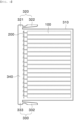
- FIG. 4 is a sectional view of a battery module according to a second preferred embodiment of the present invention taken in a horizontal direction.
- the battery module according to the second preferred embodiment of the present invention is identical in construction to the battery module according to the first preferred embodiment of the present invention described with reference to FIGS. 2 and 3 except for the second trap portion 330, and therefore a description of the same construction will be omitted.
- the second trap portion 330 of the battery module includes a second pocket portion 333 depressed by a predetermined depth in an outward direction and a second air circulation channel 322 configured to allow air to be discharged from the battery module therethrough.
- the second air circulation channel 332 is used as an air discharge passage, as previously described, the second air circulation channel may be used as an air introduction passage.
- the second pocket portion 333 is depressed by the predetermined depth to define a predetermined space, in the same manner as the first pocket portion 321, and the second air circulation channel 332 is formed so as to be bent by a predetermined angle in a direction toward a side surface of the second pocket portion 333.
- the second air circulation channel 332 is formed in a funnel shape having a width gradually increasing from an inside to an outside thereof, whereby air may be more easily introduced, and an inner passage of the second air circulation channel is narrow, whereby it is possible to inhibit discharge of the byproducts to the outside.
- the present invention provides a battery pack including a battery module having at least one of the features described above, and the battery pack may be mounted in a device, such as an electric vehicle, a hybrid electric vehicle, or a plug-in hybrid electric vehicle.
Landscapes
- Chemical & Material Sciences (AREA)
- Chemical Kinetics & Catalysis (AREA)
- Electrochemistry (AREA)
- General Chemical & Material Sciences (AREA)
- Engineering & Computer Science (AREA)
- Manufacturing & Machinery (AREA)
- Battery Mounting, Suspending (AREA)
- Secondary Cells (AREA)
- Gas Exhaust Devices For Batteries (AREA)
- Connection Of Batteries Or Terminals (AREA)
Applications Claiming Priority (2)
| Application Number | Priority Date | Filing Date | Title |
|---|---|---|---|
| KR1020210077377A KR102855781B1 (ko) | 2021-06-15 | 2021-06-15 | 절곡 형태의 트랩부가 구비된 전지 모듈 및 이를 포함하는 전지 팩 |
| PCT/KR2022/007369 WO2022265246A1 (ko) | 2021-06-15 | 2022-05-24 | 절곡 형태의 트랩부가 구비된 전지 모듈 및 이를 포함하는 전지 팩 |
Publications (3)
| Publication Number | Publication Date |
|---|---|
| EP4167367A1 EP4167367A1 (en) | 2023-04-19 |
| EP4167367A4 EP4167367A4 (en) | 2024-01-17 |
| EP4167367B1 true EP4167367B1 (en) | 2024-10-09 |
Family
ID=84526594
Family Applications (1)
| Application Number | Title | Priority Date | Filing Date |
|---|---|---|---|
| EP22825172.4A Active EP4167367B1 (en) | 2021-06-15 | 2022-05-24 | Battery module having bent trap part, and battery pack comprising same |
Country Status (10)
| Country | Link |
|---|---|
| US (1) | US20230361383A1 (es) |
| EP (1) | EP4167367B1 (es) |
| JP (1) | JP7531875B2 (es) |
| KR (1) | KR102855781B1 (es) |
| CN (1) | CN115868079A (es) |
| AU (1) | AU2022294671A1 (es) |
| ES (1) | ES2995659T3 (es) |
| HU (1) | HUE068900T2 (es) |
| PL (1) | PL4167367T3 (es) |
| WO (1) | WO2022265246A1 (es) |
Family Cites Families (32)
| Publication number | Priority date | Publication date | Assignee | Title |
|---|---|---|---|---|
| KR100684769B1 (ko) * | 2005-07-29 | 2007-02-20 | 삼성에스디아이 주식회사 | 이차 전지 모듈 |
| KR100932214B1 (ko) * | 2005-10-14 | 2009-12-16 | 주식회사 엘지화학 | 열전소자를 이용한 전지팩의 열교환 시스템 |
| JP4839955B2 (ja) * | 2006-05-11 | 2011-12-21 | トヨタ自動車株式会社 | 電池パックおよび車両 |
| JP5052057B2 (ja) * | 2006-06-30 | 2012-10-17 | 三洋電機株式会社 | 電源装置 |
| JP5030500B2 (ja) * | 2006-07-31 | 2012-09-19 | 三洋電機株式会社 | 電源装置 |
| JP5378670B2 (ja) * | 2006-10-13 | 2013-12-25 | パナソニック株式会社 | 電池パック |
| KR100981878B1 (ko) * | 2007-06-14 | 2010-09-14 | 주식회사 엘지화학 | 냉매 유량의 분배 균일성이 향상된 중대형 전지팩 케이스 |
| US8455133B2 (en) * | 2008-01-29 | 2013-06-04 | Cobasys, Llc | Battery pack |
| WO2010013902A2 (ko) * | 2008-07-26 | 2010-02-04 | 주식회사 엘지화학 | 우수한 냉각 효율성의 중대형 전지팩 케이스 |
| JP5527172B2 (ja) * | 2010-11-17 | 2014-06-18 | トヨタ自動車株式会社 | 蓄電装置 |
| JP5357987B2 (ja) * | 2012-02-13 | 2013-12-04 | 三菱重工業株式会社 | 電池用防火装置 |
| KR101669118B1 (ko) * | 2013-01-03 | 2016-10-25 | 삼성에스디아이 주식회사 | 배터리 팩 |
| JP2015135763A (ja) * | 2014-01-17 | 2015-07-27 | トヨタ自動車株式会社 | 蓄電装置 |
| KR102172846B1 (ko) * | 2014-02-10 | 2020-11-02 | 삼성에스디아이 주식회사 | 배터리 팩 |
| DE102014221684A1 (de) * | 2014-07-11 | 2016-01-14 | Robert Bosch Gmbh | Gehäuse zur Aufnahme einer Vielzahl von Batteriezellen mit einer im Gehäuse integrierten Kühlungsvorrichtung |
| US9559393B2 (en) * | 2014-09-30 | 2017-01-31 | Johnson Controls Technology Company | Battery module thermal management fluid guide assembly |
| JP6344293B2 (ja) * | 2015-04-03 | 2018-06-20 | 株式会社デンソー | 電池パック |
| US10177354B2 (en) * | 2015-09-09 | 2019-01-08 | General Electric Company | Energy storage device having improved thermal performance |
| CN108352472B (zh) * | 2015-10-28 | 2021-02-05 | 株式会社村田制作所 | 电子设备外壳以及具备该电子设备外壳的电池组 |
| KR20170069003A (ko) * | 2015-12-10 | 2017-06-20 | 삼성에스디아이 주식회사 | 배터리 모듈 |
| JP2017228496A (ja) * | 2016-06-24 | 2017-12-28 | 株式会社Gsユアサ | 蓄電装置 |
| JP2018041651A (ja) * | 2016-09-08 | 2018-03-15 | トヨタ自動車株式会社 | 電池モジュール |
| JP7068053B2 (ja) * | 2018-06-04 | 2022-05-16 | 株式会社東芝 | 冷却システム |
| KR102372348B1 (ko) * | 2018-06-08 | 2022-03-07 | 주식회사 엘지에너지솔루션 | 개선된 냉각 구조를 갖는 배터리 모듈 |
| KR102414037B1 (ko) * | 2019-03-15 | 2022-06-27 | 주식회사 엘지에너지솔루션 | 전지 모듈 및 이를 포함하는 전지팩 |
| JP7418410B2 (ja) * | 2019-03-22 | 2024-01-19 | 三洋電機株式会社 | 電池モジュール |
| JP2020161219A (ja) * | 2019-03-25 | 2020-10-01 | プライムアースEvエナジー株式会社 | 電池パックの冷却構造 |
| KR102380446B1 (ko) * | 2019-06-10 | 2022-03-30 | 주식회사 엘지에너지솔루션 | 열 폭주 현상 발생 시 냉각수가 배터리 모듈의 내부로 투입될 수 있는 구조를 갖는 배터리 팩 및 이를 포함하는 ess |
| US11271259B2 (en) * | 2019-09-04 | 2022-03-08 | Baidu Usa Llc | Airflow management for battery module cooling |
| KR102323901B1 (ko) | 2019-12-17 | 2021-11-10 | 충남대학교산학협력단 | 중수소수 및 삼중수소수 흡착용 다공성 하이드로겔, 이의 제조방법, 및 상기 다공성 하이드로겔을 이용한 중수소수 및 삼중수소수의 흡착 방법 |
| KR20220120001A (ko) * | 2021-02-22 | 2022-08-30 | 주식회사 엘지에너지솔루션 | 전지 모듈 및 이를 포함하는 전지 팩 |
| KR102857913B1 (ko) * | 2021-06-17 | 2025-09-09 | 주식회사 엘지에너지솔루션 | 개선된 벤팅 성능을 갖는 배터리 모듈 |
-
2021
- 2021-06-15 KR KR1020210077377A patent/KR102855781B1/ko active Active
-
2022
- 2022-05-24 US US18/013,650 patent/US20230361383A1/en active Pending
- 2022-05-24 HU HUE22825172A patent/HUE068900T2/hu unknown
- 2022-05-24 EP EP22825172.4A patent/EP4167367B1/en active Active
- 2022-05-24 ES ES22825172T patent/ES2995659T3/es active Active
- 2022-05-24 PL PL22825172.4T patent/PL4167367T3/pl unknown
- 2022-05-24 JP JP2023505436A patent/JP7531875B2/ja active Active
- 2022-05-24 WO PCT/KR2022/007369 patent/WO2022265246A1/ko not_active Ceased
- 2022-05-24 CN CN202280005207.0A patent/CN115868079A/zh active Pending
- 2022-05-24 AU AU2022294671A patent/AU2022294671A1/en active Pending
Also Published As
| Publication number | Publication date |
|---|---|
| US20230361383A1 (en) | 2023-11-09 |
| JP7531875B2 (ja) | 2024-08-13 |
| KR20220167965A (ko) | 2022-12-22 |
| JP2023535778A (ja) | 2023-08-21 |
| CN115868079A (zh) | 2023-03-28 |
| EP4167367A1 (en) | 2023-04-19 |
| ES2995659T3 (en) | 2025-02-10 |
| EP4167367A4 (en) | 2024-01-17 |
| PL4167367T3 (pl) | 2024-12-23 |
| HUE068900T2 (hu) | 2025-02-28 |
| KR102855781B1 (ko) | 2025-09-05 |
| AU2022294671A1 (en) | 2023-02-23 |
| WO2022265246A1 (ko) | 2022-12-22 |
Similar Documents
| Publication | Publication Date | Title |
|---|---|---|
| EP4087039B1 (en) | Battery module having partition wall and thermal insulation layer for fire inhibition | |
| US20250379310A1 (en) | Battery module capable of preventing movement of gas to adjacent module | |
| EP4191750B1 (en) | Battery pack with improved cooling performance and device comprising same | |
| EP4087020A1 (en) | Battery pack having battery modules stacked into multiple layers | |
| US20230128563A1 (en) | Battery module having pocket capable of capturing flare and spark ejected during swelling | |
| US12537248B2 (en) | Battery module having fire transition prevention structure and battery pack including the same | |
| EP4239766A1 (en) | Battery pack | |
| EP4167367B1 (en) | Battery module having bent trap part, and battery pack comprising same | |
| EP4207446B1 (en) | Pouch-shaped battery cell having easily coolable structure and manufacturing method thereof | |
| EP4080646B1 (en) | Battery pack having refrigerant circulation channel provided in pack case | |
| EP4243194B1 (en) | Pouch-shaped battery cell with improved thermal stability | |
| US20260031456A1 (en) | Battery pack having excellent impact resistance | |
| US20250149693A1 (en) | Secondary battery and battery pack including the same | |
| KR20250147389A (ko) | 향상된 냉각성능을 가지는 배터리 팩 | |
| KR20250067716A (ko) | 전지팩 및 이를 포함하는 디바이스 | |
| CN121548907A (zh) | 电池组和包括该电池组的设备 |
Legal Events
| Date | Code | Title | Description |
|---|---|---|---|
| STAA | Information on the status of an ep patent application or granted ep patent |
Free format text: STATUS: THE INTERNATIONAL PUBLICATION HAS BEEN MADE |
|
| PUAI | Public reference made under article 153(3) epc to a published international application that has entered the european phase |
Free format text: ORIGINAL CODE: 0009012 |
|
| STAA | Information on the status of an ep patent application or granted ep patent |
Free format text: STATUS: REQUEST FOR EXAMINATION WAS MADE |
|
| 17P | Request for examination filed |
Effective date: 20230110 |
|
| AK | Designated contracting states |
Kind code of ref document: A1 Designated state(s): AL AT BE BG CH CY CZ DE DK EE ES FI FR GB GR HR HU IE IS IT LI LT LU LV MC MK MT NL NO PL PT RO RS SE SI SK SM TR |
|
| A4 | Supplementary search report drawn up and despatched |
Effective date: 20231214 |
|
| RIC1 | Information provided on ipc code assigned before grant |
Ipc: H01M 10/6553 20140101ALI20231208BHEP Ipc: H01M 10/625 20140101ALI20231208BHEP Ipc: H01M 50/211 20210101ALI20231208BHEP Ipc: H01M 50/502 20210101ALI20231208BHEP Ipc: H01M 10/6566 20140101ALI20231208BHEP Ipc: H01M 50/383 20210101ALI20231208BHEP Ipc: H01M 50/30 20210101AFI20231208BHEP |
|
| GRAP | Despatch of communication of intention to grant a patent |
Free format text: ORIGINAL CODE: EPIDOSNIGR1 |
|
| STAA | Information on the status of an ep patent application or granted ep patent |
Free format text: STATUS: GRANT OF PATENT IS INTENDED |
|
| DAV | Request for validation of the european patent (deleted) | ||
| DAX | Request for extension of the european patent (deleted) | ||
| INTG | Intention to grant announced |
Effective date: 20240527 |
|
| P01 | Opt-out of the competence of the unified patent court (upc) registered |
Free format text: CASE NUMBER: APP_42909/2024 Effective date: 20240722 |
|
| GRAS | Grant fee paid |
Free format text: ORIGINAL CODE: EPIDOSNIGR3 |
|
| GRAA | (expected) grant |
Free format text: ORIGINAL CODE: 0009210 |
|
| STAA | Information on the status of an ep patent application or granted ep patent |
Free format text: STATUS: THE PATENT HAS BEEN GRANTED |
|
| REG | Reference to a national code |
Ref country code: DE Ref legal event code: R082 Ref document number: 602022006739 Country of ref document: DE Representative=s name: HOFFMANN EITLE PATENT- UND RECHTSANWAELTE PART, DE |
|
| AK | Designated contracting states |
Kind code of ref document: B1 Designated state(s): AL AT BE BG CH CY CZ DE DK EE ES FI FR GB GR HR HU IE IS IT LI LT LU LV MC MK MT NL NO PL PT RO RS SE SI SK SM TR |
|
| REG | Reference to a national code |
Ref country code: CH Ref legal event code: EP |
|
| REG | Reference to a national code |
Ref country code: IE Ref legal event code: FG4D Ref country code: NL Ref legal event code: FP |
|
| REG | Reference to a national code |
Ref country code: DE Ref legal event code: R096 Ref document number: 602022006739 Country of ref document: DE |
|
| REG | Reference to a national code |
Ref country code: SE Ref legal event code: TRGR |
|
| REG | Reference to a national code |
Ref country code: LT Ref legal event code: MG9D |
|
| REG | Reference to a national code |
Ref country code: ES Ref legal event code: FG2A Ref document number: 2995659 Country of ref document: ES Kind code of ref document: T3 Effective date: 20250210 |
|
| REG | Reference to a national code |
Ref country code: HU Ref legal event code: AG4A Ref document number: E068900 Country of ref document: HU |
|
| REG | Reference to a national code |
Ref country code: AT Ref legal event code: MK05 Ref document number: 1731610 Country of ref document: AT Kind code of ref document: T Effective date: 20241009 |
|
| PG25 | Lapsed in a contracting state [announced via postgrant information from national office to epo] |
Ref country code: IS Free format text: LAPSE BECAUSE OF FAILURE TO SUBMIT A TRANSLATION OF THE DESCRIPTION OR TO PAY THE FEE WITHIN THE PRESCRIBED TIME-LIMIT Effective date: 20250209 Ref country code: HR Free format text: LAPSE BECAUSE OF FAILURE TO SUBMIT A TRANSLATION OF THE DESCRIPTION OR TO PAY THE FEE WITHIN THE PRESCRIBED TIME-LIMIT Effective date: 20241009 Ref country code: PT Free format text: LAPSE BECAUSE OF FAILURE TO SUBMIT A TRANSLATION OF THE DESCRIPTION OR TO PAY THE FEE WITHIN THE PRESCRIBED TIME-LIMIT Effective date: 20250210 |
|
| PG25 | Lapsed in a contracting state [announced via postgrant information from national office to epo] |
Ref country code: FI Free format text: LAPSE BECAUSE OF FAILURE TO SUBMIT A TRANSLATION OF THE DESCRIPTION OR TO PAY THE FEE WITHIN THE PRESCRIBED TIME-LIMIT Effective date: 20241009 |
|
| PG25 | Lapsed in a contracting state [announced via postgrant information from national office to epo] |
Ref country code: BG Free format text: LAPSE BECAUSE OF FAILURE TO SUBMIT A TRANSLATION OF THE DESCRIPTION OR TO PAY THE FEE WITHIN THE PRESCRIBED TIME-LIMIT Effective date: 20241009 |
|
| PG25 | Lapsed in a contracting state [announced via postgrant information from national office to epo] |
Ref country code: NO Free format text: LAPSE BECAUSE OF FAILURE TO SUBMIT A TRANSLATION OF THE DESCRIPTION OR TO PAY THE FEE WITHIN THE PRESCRIBED TIME-LIMIT Effective date: 20250109 |
|
| PG25 | Lapsed in a contracting state [announced via postgrant information from national office to epo] |
Ref country code: GR Free format text: LAPSE BECAUSE OF FAILURE TO SUBMIT A TRANSLATION OF THE DESCRIPTION OR TO PAY THE FEE WITHIN THE PRESCRIBED TIME-LIMIT Effective date: 20250110 Ref country code: LV Free format text: LAPSE BECAUSE OF FAILURE TO SUBMIT A TRANSLATION OF THE DESCRIPTION OR TO PAY THE FEE WITHIN THE PRESCRIBED TIME-LIMIT Effective date: 20241009 Ref country code: AT Free format text: LAPSE BECAUSE OF FAILURE TO SUBMIT A TRANSLATION OF THE DESCRIPTION OR TO PAY THE FEE WITHIN THE PRESCRIBED TIME-LIMIT Effective date: 20241009 |
|
| PG25 | Lapsed in a contracting state [announced via postgrant information from national office to epo] |
Ref country code: RS Free format text: LAPSE BECAUSE OF FAILURE TO SUBMIT A TRANSLATION OF THE DESCRIPTION OR TO PAY THE FEE WITHIN THE PRESCRIBED TIME-LIMIT Effective date: 20250109 |
|
| PGFP | Annual fee paid to national office [announced via postgrant information from national office to epo] |
Ref country code: NL Payment date: 20250422 Year of fee payment: 4 |
|
| PG25 | Lapsed in a contracting state [announced via postgrant information from national office to epo] |
Ref country code: SM Free format text: LAPSE BECAUSE OF FAILURE TO SUBMIT A TRANSLATION OF THE DESCRIPTION OR TO PAY THE FEE WITHIN THE PRESCRIBED TIME-LIMIT Effective date: 20241009 |
|
| PGFP | Annual fee paid to national office [announced via postgrant information from national office to epo] |
Ref country code: PL Payment date: 20250423 Year of fee payment: 4 Ref country code: DE Payment date: 20250422 Year of fee payment: 4 |
|
| PG25 | Lapsed in a contracting state [announced via postgrant information from national office to epo] |
Ref country code: DK Free format text: LAPSE BECAUSE OF FAILURE TO SUBMIT A TRANSLATION OF THE DESCRIPTION OR TO PAY THE FEE WITHIN THE PRESCRIBED TIME-LIMIT Effective date: 20241009 |
|
| PGFP | Annual fee paid to national office [announced via postgrant information from national office to epo] |
Ref country code: ES Payment date: 20250613 Year of fee payment: 4 |
|
| REG | Reference to a national code |
Ref country code: DE Ref legal event code: R097 Ref document number: 602022006739 Country of ref document: DE |
|
| PGFP | Annual fee paid to national office [announced via postgrant information from national office to epo] |
Ref country code: HU Payment date: 20250526 Year of fee payment: 4 |
|
| PGFP | Annual fee paid to national office [announced via postgrant information from national office to epo] |
Ref country code: IT Payment date: 20250531 Year of fee payment: 4 Ref country code: BE Payment date: 20250407 Year of fee payment: 4 |
|
| PG25 | Lapsed in a contracting state [announced via postgrant information from national office to epo] |
Ref country code: EE Free format text: LAPSE BECAUSE OF FAILURE TO SUBMIT A TRANSLATION OF THE DESCRIPTION OR TO PAY THE FEE WITHIN THE PRESCRIBED TIME-LIMIT Effective date: 20241009 |
|
| PGFP | Annual fee paid to national office [announced via postgrant information from national office to epo] |
Ref country code: FR Payment date: 20250422 Year of fee payment: 4 |
|
| PG25 | Lapsed in a contracting state [announced via postgrant information from national office to epo] |
Ref country code: RO Free format text: LAPSE BECAUSE OF FAILURE TO SUBMIT A TRANSLATION OF THE DESCRIPTION OR TO PAY THE FEE WITHIN THE PRESCRIBED TIME-LIMIT Effective date: 20241009 |
|
| PG25 | Lapsed in a contracting state [announced via postgrant information from national office to epo] |
Ref country code: SK Free format text: LAPSE BECAUSE OF FAILURE TO SUBMIT A TRANSLATION OF THE DESCRIPTION OR TO PAY THE FEE WITHIN THE PRESCRIBED TIME-LIMIT Effective date: 20241009 |
|
| PGFP | Annual fee paid to national office [announced via postgrant information from national office to epo] |
Ref country code: TR Payment date: 20250422 Year of fee payment: 4 |
|
| PG25 | Lapsed in a contracting state [announced via postgrant information from national office to epo] |
Ref country code: CZ Free format text: LAPSE BECAUSE OF FAILURE TO SUBMIT A TRANSLATION OF THE DESCRIPTION OR TO PAY THE FEE WITHIN THE PRESCRIBED TIME-LIMIT Effective date: 20241009 |
|
| PGFP | Annual fee paid to national office [announced via postgrant information from national office to epo] |
Ref country code: SE Payment date: 20250422 Year of fee payment: 4 |
|
| PLBE | No opposition filed within time limit |
Free format text: ORIGINAL CODE: 0009261 |
|
| STAA | Information on the status of an ep patent application or granted ep patent |
Free format text: STATUS: NO OPPOSITION FILED WITHIN TIME LIMIT |
|
| 26N | No opposition filed |
Effective date: 20250710 |
|
| REG | Reference to a national code |
Ref country code: CH Ref legal event code: H13 Free format text: ST27 STATUS EVENT CODE: U-0-0-H10-H13 (AS PROVIDED BY THE NATIONAL OFFICE) Effective date: 20251223 |
|
| PG25 | Lapsed in a contracting state [announced via postgrant information from national office to epo] |
Ref country code: LU Free format text: LAPSE BECAUSE OF NON-PAYMENT OF DUE FEES Effective date: 20250524 |
|
| PG25 | Lapsed in a contracting state [announced via postgrant information from national office to epo] |
Ref country code: CH Free format text: LAPSE BECAUSE OF NON-PAYMENT OF DUE FEES Effective date: 20250531 |
|
| PG25 | Lapsed in a contracting state [announced via postgrant information from national office to epo] |
Ref country code: MC Free format text: LAPSE BECAUSE OF FAILURE TO SUBMIT A TRANSLATION OF THE DESCRIPTION OR TO PAY THE FEE WITHIN THE PRESCRIBED TIME-LIMIT Effective date: 20241009 |