EP4159983A1 - Steuerungsverfahren und steuerungsvorrichtung für einen verbrennungsmotor - Google Patents
Steuerungsverfahren und steuerungsvorrichtung für einen verbrennungsmotor Download PDFInfo
- Publication number
- EP4159983A1 EP4159983A1 EP20937685.4A EP20937685A EP4159983A1 EP 4159983 A1 EP4159983 A1 EP 4159983A1 EP 20937685 A EP20937685 A EP 20937685A EP 4159983 A1 EP4159983 A1 EP 4159983A1
- Authority
- EP
- European Patent Office
- Prior art keywords
- electric heating
- heating catalyst
- internal combustion
- combustion engine
- temperature
- Prior art date
- Legal status (The legal status is an assumption and is not a legal conclusion. Google has not performed a legal analysis and makes no representation as to the accuracy of the status listed.)
- Granted
Links
Images


Classifications
-
- F—MECHANICAL ENGINEERING; LIGHTING; HEATING; WEAPONS; BLASTING
- F01—MACHINES OR ENGINES IN GENERAL; ENGINE PLANTS IN GENERAL; STEAM ENGINES
- F01N—GAS-FLOW SILENCERS OR EXHAUST APPARATUS FOR MACHINES OR ENGINES IN GENERAL; GAS-FLOW SILENCERS OR EXHAUST APPARATUS FOR INTERNAL-COMBUSTION ENGINES
- F01N3/00—Exhaust or silencing apparatus having means for purifying, rendering innocuous, or otherwise treating exhaust
- F01N3/08—Exhaust or silencing apparatus having means for purifying, rendering innocuous, or otherwise treating exhaust for rendering innocuous
- F01N3/10—Exhaust or silencing apparatus having means for purifying, rendering innocuous, or otherwise treating exhaust for rendering innocuous by thermal or catalytic conversion of noxious components of exhaust
- F01N3/18—Exhaust or silencing apparatus having means for purifying, rendering innocuous, or otherwise treating exhaust for rendering innocuous by thermal or catalytic conversion of noxious components of exhaust characterised by methods of operation; Control
- F01N3/20—Exhaust or silencing apparatus having means for purifying, rendering innocuous, or otherwise treating exhaust for rendering innocuous by thermal or catalytic conversion of noxious components of exhaust characterised by methods of operation; Control specially adapted for catalytic conversion
- F01N3/2006—Periodically heating or cooling catalytic reactors, e.g. at cold starting or overheating
- F01N3/2013—Periodically heating or cooling catalytic reactors, e.g. at cold starting or overheating using electric or magnetic heating means
-
- F—MECHANICAL ENGINEERING; LIGHTING; HEATING; WEAPONS; BLASTING
- F01—MACHINES OR ENGINES IN GENERAL; ENGINE PLANTS IN GENERAL; STEAM ENGINES
- F01N—GAS-FLOW SILENCERS OR EXHAUST APPARATUS FOR MACHINES OR ENGINES IN GENERAL; GAS-FLOW SILENCERS OR EXHAUST APPARATUS FOR INTERNAL-COMBUSTION ENGINES
- F01N11/00—Monitoring or diagnostic devices for exhaust-gas treatment apparatus
-
- F—MECHANICAL ENGINEERING; LIGHTING; HEATING; WEAPONS; BLASTING
- F01—MACHINES OR ENGINES IN GENERAL; ENGINE PLANTS IN GENERAL; STEAM ENGINES
- F01N—GAS-FLOW SILENCERS OR EXHAUST APPARATUS FOR MACHINES OR ENGINES IN GENERAL; GAS-FLOW SILENCERS OR EXHAUST APPARATUS FOR INTERNAL-COMBUSTION ENGINES
- F01N3/00—Exhaust or silencing apparatus having means for purifying, rendering innocuous, or otherwise treating exhaust
- F01N3/02—Exhaust or silencing apparatus having means for purifying, rendering innocuous, or otherwise treating exhaust for cooling, or for removing solid constituents of, exhaust
- F01N3/05—Exhaust or silencing apparatus having means for purifying, rendering innocuous, or otherwise treating exhaust for cooling, or for removing solid constituents of, exhaust by means of air, e.g. by mixing exhaust with air
-
- F—MECHANICAL ENGINEERING; LIGHTING; HEATING; WEAPONS; BLASTING
- F01—MACHINES OR ENGINES IN GENERAL; ENGINE PLANTS IN GENERAL; STEAM ENGINES
- F01N—GAS-FLOW SILENCERS OR EXHAUST APPARATUS FOR MACHINES OR ENGINES IN GENERAL; GAS-FLOW SILENCERS OR EXHAUST APPARATUS FOR INTERNAL-COMBUSTION ENGINES
- F01N3/00—Exhaust or silencing apparatus having means for purifying, rendering innocuous, or otherwise treating exhaust
- F01N3/08—Exhaust or silencing apparatus having means for purifying, rendering innocuous, or otherwise treating exhaust for rendering innocuous
- F01N3/10—Exhaust or silencing apparatus having means for purifying, rendering innocuous, or otherwise treating exhaust for rendering innocuous by thermal or catalytic conversion of noxious components of exhaust
- F01N3/24—Exhaust or silencing apparatus having means for purifying, rendering innocuous, or otherwise treating exhaust for rendering innocuous by thermal or catalytic conversion of noxious components of exhaust characterised by constructional aspects of converting apparatus
- F01N3/30—Arrangements for supply of additional air
- F01N3/32—Arrangements for supply of additional air using air pump
-
- F—MECHANICAL ENGINEERING; LIGHTING; HEATING; WEAPONS; BLASTING
- F01—MACHINES OR ENGINES IN GENERAL; ENGINE PLANTS IN GENERAL; STEAM ENGINES
- F01N—GAS-FLOW SILENCERS OR EXHAUST APPARATUS FOR MACHINES OR ENGINES IN GENERAL; GAS-FLOW SILENCERS OR EXHAUST APPARATUS FOR INTERNAL-COMBUSTION ENGINES
- F01N9/00—Electrical control of exhaust gas treating apparatus
-
- F—MECHANICAL ENGINEERING; LIGHTING; HEATING; WEAPONS; BLASTING
- F01—MACHINES OR ENGINES IN GENERAL; ENGINE PLANTS IN GENERAL; STEAM ENGINES
- F01N—GAS-FLOW SILENCERS OR EXHAUST APPARATUS FOR MACHINES OR ENGINES IN GENERAL; GAS-FLOW SILENCERS OR EXHAUST APPARATUS FOR INTERNAL-COMBUSTION ENGINES
- F01N2240/00—Combination or association of two or more different exhaust treating devices, or of at least one such device with an auxiliary device, not covered by indexing codes F01N2230/00 or F01N2250/00, one of the devices being
- F01N2240/16—Combination or association of two or more different exhaust treating devices, or of at least one such device with an auxiliary device, not covered by indexing codes F01N2230/00 or F01N2250/00, one of the devices being an electric heater, i.e. a resistance heater
-
- F—MECHANICAL ENGINEERING; LIGHTING; HEATING; WEAPONS; BLASTING
- F01—MACHINES OR ENGINES IN GENERAL; ENGINE PLANTS IN GENERAL; STEAM ENGINES
- F01N—GAS-FLOW SILENCERS OR EXHAUST APPARATUS FOR MACHINES OR ENGINES IN GENERAL; GAS-FLOW SILENCERS OR EXHAUST APPARATUS FOR INTERNAL-COMBUSTION ENGINES
- F01N2270/00—Mixing air with exhaust gases
- F01N2270/02—Mixing air with exhaust gases for cooling exhaust gases or the apparatus
-
- F—MECHANICAL ENGINEERING; LIGHTING; HEATING; WEAPONS; BLASTING
- F01—MACHINES OR ENGINES IN GENERAL; ENGINE PLANTS IN GENERAL; STEAM ENGINES
- F01N—GAS-FLOW SILENCERS OR EXHAUST APPARATUS FOR MACHINES OR ENGINES IN GENERAL; GAS-FLOW SILENCERS OR EXHAUST APPARATUS FOR INTERNAL-COMBUSTION ENGINES
- F01N2550/00—Monitoring or diagnosing the deterioration of exhaust systems
- F01N2550/22—Monitoring or diagnosing the deterioration of exhaust systems of electric heaters for exhaust systems or their power supply
-
- F—MECHANICAL ENGINEERING; LIGHTING; HEATING; WEAPONS; BLASTING
- F01—MACHINES OR ENGINES IN GENERAL; ENGINE PLANTS IN GENERAL; STEAM ENGINES
- F01N—GAS-FLOW SILENCERS OR EXHAUST APPARATUS FOR MACHINES OR ENGINES IN GENERAL; GAS-FLOW SILENCERS OR EXHAUST APPARATUS FOR INTERNAL-COMBUSTION ENGINES
- F01N2560/00—Exhaust systems with means for detecting or measuring exhaust gas components or characteristics
- F01N2560/06—Exhaust systems with means for detecting or measuring exhaust gas components or characteristics the means being a temperature sensor
-
- F—MECHANICAL ENGINEERING; LIGHTING; HEATING; WEAPONS; BLASTING
- F01—MACHINES OR ENGINES IN GENERAL; ENGINE PLANTS IN GENERAL; STEAM ENGINES
- F01N—GAS-FLOW SILENCERS OR EXHAUST APPARATUS FOR MACHINES OR ENGINES IN GENERAL; GAS-FLOW SILENCERS OR EXHAUST APPARATUS FOR INTERNAL-COMBUSTION ENGINES
- F01N2900/00—Details of electrical control or of the monitoring of the exhaust gas treating apparatus
- F01N2900/04—Methods of control or diagnosing
- F01N2900/0421—Methods of control or diagnosing using an increment counter when a predetermined event occurs
-
- F—MECHANICAL ENGINEERING; LIGHTING; HEATING; WEAPONS; BLASTING
- F01—MACHINES OR ENGINES IN GENERAL; ENGINE PLANTS IN GENERAL; STEAM ENGINES
- F01N—GAS-FLOW SILENCERS OR EXHAUST APPARATUS FOR MACHINES OR ENGINES IN GENERAL; GAS-FLOW SILENCERS OR EXHAUST APPARATUS FOR INTERNAL-COMBUSTION ENGINES
- F01N2900/00—Details of electrical control or of the monitoring of the exhaust gas treating apparatus
- F01N2900/06—Parameters used for exhaust control or diagnosing
- F01N2900/10—Parameters used for exhaust control or diagnosing said parameters being related to the vehicle or its components
- F01N2900/104—Battery status
-
- F—MECHANICAL ENGINEERING; LIGHTING; HEATING; WEAPONS; BLASTING
- F01—MACHINES OR ENGINES IN GENERAL; ENGINE PLANTS IN GENERAL; STEAM ENGINES
- F01N—GAS-FLOW SILENCERS OR EXHAUST APPARATUS FOR MACHINES OR ENGINES IN GENERAL; GAS-FLOW SILENCERS OR EXHAUST APPARATUS FOR INTERNAL-COMBUSTION ENGINES
- F01N2900/00—Details of electrical control or of the monitoring of the exhaust gas treating apparatus
- F01N2900/06—Parameters used for exhaust control or diagnosing
- F01N2900/14—Parameters used for exhaust control or diagnosing said parameters being related to the exhaust gas
- F01N2900/1404—Exhaust gas temperature
-
- F—MECHANICAL ENGINEERING; LIGHTING; HEATING; WEAPONS; BLASTING
- F01—MACHINES OR ENGINES IN GENERAL; ENGINE PLANTS IN GENERAL; STEAM ENGINES
- F01N—GAS-FLOW SILENCERS OR EXHAUST APPARATUS FOR MACHINES OR ENGINES IN GENERAL; GAS-FLOW SILENCERS OR EXHAUST APPARATUS FOR INTERNAL-COMBUSTION ENGINES
- F01N2900/00—Details of electrical control or of the monitoring of the exhaust gas treating apparatus
- F01N2900/06—Parameters used for exhaust control or diagnosing
- F01N2900/16—Parameters used for exhaust control or diagnosing said parameters being related to the exhaust apparatus, e.g. particulate filter or catalyst
- F01N2900/1602—Temperature of exhaust gas apparatus
-
- Y—GENERAL TAGGING OF NEW TECHNOLOGICAL DEVELOPMENTS; GENERAL TAGGING OF CROSS-SECTIONAL TECHNOLOGIES SPANNING OVER SEVERAL SECTIONS OF THE IPC; TECHNICAL SUBJECTS COVERED BY FORMER USPC CROSS-REFERENCE ART COLLECTIONS [XRACs] AND DIGESTS
- Y02—TECHNOLOGIES OR APPLICATIONS FOR MITIGATION OR ADAPTATION AGAINST CLIMATE CHANGE
- Y02T—CLIMATE CHANGE MITIGATION TECHNOLOGIES RELATED TO TRANSPORTATION
- Y02T10/00—Road transport of goods or passengers
- Y02T10/10—Internal combustion engine [ICE] based vehicles
- Y02T10/12—Improving ICE efficiencies
Definitions
- the present invention relates to a control method and a control device for an internal combustion engine having an electric heating catalyst in an exhaust system.
- an electric heating catalyst that can be forcibly heated by energization is used in an exhaust system.
- preheating the electric heating catalyst by energizing the electric heating catalyst before starting the internal combustion engine it is possible to obtain an exhaust gas purification action at an early stage after the start of the internal combustion engine.
- Patent Document 1 discloses that the electric heating catalyst is energized until the total sum of an energization amount reaches a target energization amount. Further, when the energization is interrupted by a start request of the internal combustion engine, an energization amount after resumption of the preheating is increased by taking a cooling amount during the interruption of the preheating into account.
- Patent Document 1 Japanese Unexamined Patent Application Publication No. JP2015-075068
- the energization is forbidden or stopped until the temperature of the electric heating catalyst is lowered to such a temperature as not to cause an excessive temperature rise even if a normal preheating is performed, then the electric heating catalyst is surely protected.
- Fig. 1 is an explanatory drawing schematically showing a system configuration of an internal combustion engine 1 according to the present invention.
- the internal combustion engine 1 is, for instance, a spark ignition internal combustion engine using gasoline as fuel.
- the internal combustion engine 1 is mounted on the vehicle together with a transmission, and the vehicle is directly driven by an output of the internal combustion engine 1.
- the internal combustion engine 1 is mounted on the vehicle together with an electric motor, and both of the electric motor and the internal combustion engine 1 are used as travelling drive sources.
- a so-called series hybrid vehicle the internal combustion engine 1 is used to drive a generator, and the vehicle travels by an electric motor with generated power.
- the internal combustion engine 1 has an intake system (not shown) and an exhaust system.
- An exhaust passage 2 constituting the exhaust system extends from the internal combustion engine 1 to a rear end of the vehicle.
- a catalyst device is provided in the exhaust system in order to purify exhaust gas emitted from the internal combustion engine 1.
- the catalyst device includes a pre-catalyst 3 that is provided in the vicinity of an outlet of an exhaust manifold 2a in the exhaust passage 2 and a main catalyst 4 that is located at a downstream side with respect to the pre-catalyst 3 and arranged under a vehicle floor.
- the pre-catalyst 3 further includes an electric heating catalyst 5 that constitutes an upstream portion of the pre-catalyst 3 and a catalyst 6 that constitutes a downstream portion of the pre-catalyst 3, and both these catalysts are accommodated in one casing.
- the electric heating catalyst 5 has, for instance, a structure in which a heating element that generates heat by being energized is used as a catalyst carrier, and its surface is coated with an appropriate catalyst metal, which becomes a three-way catalyst or an oxidation catalyst, as slurry.
- the electric heating catalyst 5 could have a structure in which an independent heater is combined with the catalyst carrier.
- the catalyst 6 has, for instance, a structure in which a surface of a monolithic ceramic catalyst in which fine passages are formed is coated with an appropriate catalyst metal, which becomes a three-way catalyst or an oxidation catalyst, as slurry.
- the main catalyst 4 has, for instance, a structure in which a surface of a monolithic ceramic catalyst in which fine passages are formed is coated with an appropriate catalyst metal, which becomes a three-way catalyst or an oxidation catalyst, as slurry.
- Energization of the electric heating catalyst 5 is controlled by an engine controller 8.
- the engine controller 8 uses, as a power source, a 12-volt battery (not shown) that supplies power to general electrical components of the vehicle, whereas the electric heating catalyst 5 uses, as a power source, a 48-volt battery (not shown) that can supply a greater power.
- the electric heating catalyst 5 receives the power from the 48-volt battery through a relay, a switching element and so on.
- the 12-volt battery may be used as the power source of the electric heating catalyst 5.
- the engine controller 8 executes a variety of controls of the internal combustion engine 1 typified by control of a fuel injection amount and an injection timing by a fuel injection valve (not shown) of the internal combustion engine 1, control of an ignition timing by an ignition plug (not shown) and control of an opening degree of a throttle valve (not shown) .
- controls of the internal combustion engine 1 typified by control of a fuel injection amount and an injection timing by a fuel injection valve (not shown) of the internal combustion engine 1, control of an ignition timing by an ignition plug (not shown) and control of an opening degree of a throttle valve (not shown) .
- the energization of the electric heating catalyst 5 for preheating the electric heating catalyst 5 at a cold start is controlled.
- the engine controller 8 inputs a number of detection signals from a variety of sensors and other controllers.
- an air flow meter 11 for detecting an intake air amount of the internal combustion engine 1 a crank angle sensor 12 for detecting a rotation speed of the internal combustion engine 1, a water temperature sensor 13 for detecting a cooling water temperature, an oil temperature sensor 14 for detecting a lubricating oil temperature and an air-fuel ratio sensor 15 for detecting an exhaust air-fuel ratio in the exhaust passage 2 for air-fuel ratio feedback control are provided, and their detection signals are input to the engine controller 8.
- a battery controller 16 that monitors a state of the 48-volt battery supplying the power to the electric heating catalyst 5 sends a signal indicating a charge amount of the 48-volt battery, i.e. an SOC of the 48-volt battery, to the engine controller 8.
- a door switch 17 that detects an opening operation of driver's seat door of the vehicle is connected to the engine controller 8.
- the energization of the electric heating catalyst 5 is started, that is, the preheating of the electric heating catalyst 5 is started. It is noted that if the cooling water temperature etc. indicate that the internal combustion engine 1 is in a warm-up state, the preheating is not carried out. After the start of the preheating, temperature of the electric heating catalyst 5 is sequentially estimated by integration or accumulation etc. of an energization amount of the electric heating catalyst 5. When this estimated temperature reaches a predetermined temperature, it is judged that the preheating is completed, and the energization of the electric heating catalyst 5 is ended.
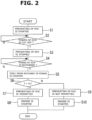
- Fig. 2 is a flow chart showing a flow of a process of a first embodiment.
- This flow chart does not represent a computer program itself, but is an explanatory flow chart showing the flow of the process in time sequence.
- the energization of the electric heating catalyst 5 (abbreviated to EHC in the flow chart etc.) is started, that is, the preheating of the electric heating catalyst 5 is started (step S1) .
- a judgment is made as to whether or not an event in which the power of the engine controller 8 (abbreviated to ECM in the flow chart etc.) is lost (cut off) has occurred (step S2). If the loss of the power of the engine controller 8 does not occur until the preheating is completed, as described above, when the estimated temperature of the electric heating catalyst 5 reaches the predetermined temperature, the energization is ended.
- step S3 When the power of the engine controller 8 is cut off, the energization of the electric heating catalyst 5 is stopped by and according to this cut-off (step S3) . Afterwards, when the power of the engine controller 8 is recovered (step S4), the engine controller 8 starts to measure a timer t that measures an elapsed time from a time of this recovery of the power (step S5). Then, the engine controller 8 compares a value of this timer t with a previously set predetermined threshold value tc1 (step S6) . When the value of the timer t, i.e.
- the elapsed time from the recovery of the power is the threshold value tc1 or less, as shown as step S9, the energization (the preheating) of the electric heating catalyst 5 is forbidden or stopped. If there is a start request of the internal combustion engine 1 during this period, as shown as step S10, the internal combustion engine 1 is started without preheating the electric heating catalyst 5.
- step S7 When the elapsed time t from the recovery of the power exceeds the threshold value tc1, as shown as step S7, the energization of the electric heating catalyst 5, i.e. the preheating of the electric heating catalyst 5, is performed as usual. That is, the preheating from an initial state in which the electric heating catalyst 5 is regarded as being in a cold state is performed again. Then, the internal combustion engine 1 is started by and according to the start request of the internal combustion engine 1 (step S8).
- a time required for the preheating is, e.g. about several seconds.
- the threshold value tc1 corresponds to a cooling period by natural heat radiation.
- the threshold value tc1 is set as a sufficient time for the temperature of the electric heating catalyst 5 (particularly, its heater portion) to lower to a certain temperature (a temperature at which there is no hindrance even if the preheating is resumed) assuming that the temperature of the electric heating catalyst 5 has risen to a preheating completion temperature before the loss of the power of the engine controller 8. For instance, it is several tens of seconds to several minutes.
- the cooling period is fixedly set to a necessary time with consideration given to a possibility that the temperature of the electric heating catalyst 5 is in the vicinity of the preheating completion temperature at a time of the recovery of the power.
- the energization of the electric heating catalyst 5 is forbidden or stopped until the cooling period necessary for the temperature of the electric heating catalyst 5 to fall elapses after the recovery of the power of the engine controller 8. Therefore, an excessive temperature rise of the electric heating catalyst 5 due to re-preheating (re-energization) is avoided.
- Fig. 3 is a flow chart showing a flow of a process of a second embodiment. Steps S11 to S15 are the same as steps S1 to S5 of the first embodiment.
- the energization of the electric heating catalyst 5 is started, that is, the preheating of the electric heating catalyst 5 is started (step S11).
- step S13 When the power of the engine controller 8 is cut off, the energization of the electric heating catalyst 5 is stopped by and according to this cut-off (step S13) . Afterwards, when the power of the engine controller 8 is recovered (step S14), the engine controller 8 starts to measure a timer t that measures an elapsed time from a time of this recovery of the power (step S15).
- a change amount (a variation) ⁇ SOC of the SOC of the 48-volt battery is determined, and on the basis of this ⁇ SOC, a threshold value tc2 corresponding to the cooling period is determined (step S16).
- the engine controller 8 compares a value of the timer t with the threshold value tc2.
- the value of the timer t i.e. the elapsed time from the recovery of the power
- the threshold value tc2 or less i.e. the elapsed time from the recovery of the power
- the energization (the preheating) of the electric heating catalyst 5 is forbidden or stopped. If there is a start request of the internal combustion engine 1 during this period, as shown as step S21, the internal combustion engine 1 is started without preheating the electric heating catalyst 5.
- step S18 When the elapsed time t from the recovery of the power exceeds the threshold value tc2, as shown as step S18, the energization of the electric heating catalyst 5, i.e. the preheating of the electric heating catalyst 5, is performed as usual. That is, the preheating from an initial state in which the electric heating catalyst 5 is regarded as being in a cold state is performed again. Then, the internal combustion engine 1 is started by and according to the start request of the internal combustion engine 1 (step S19).
- the cooling period which is a waiting time until the preheating is resumed, is set to be shorter than that in the first embodiment.
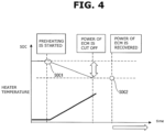
- Fig. 4 shows changes in the SOC and the temperature of the electric heating catalyst 5 (particularly, its heater portion) with the lapse of time from the start of the energization before the loss of the power.
- the preheating is started by and according to the opening operation of driver's seat door and so on, the temperature of the electric heating catalyst 5 gradually increases, and the charge amount of the 48-volt battery, i.e. the SOC of the 48-volt battery, gradually decreases.
- the temperature (the estimated temperature) of the electric heating catalyst 5 after the loss becomes unknown.
- a value SOC1 of the SOC at the time of the start of the energization is stored in a nonvolatile memory of the engine controller 8 or the battery controller 16. Then, a value SOC2 of the SOC at the time of the recovery of the power is estimated by the battery controller 16, for instance, on the basis of a voltage of the 48-volt battery.
- Fig. 5 shows the temperature of the electric heating catalyst 5 at the time of the recovery of the power and a subsequent change in the temperature of the electric heating catalyst 5 by natural cooling (self-cooling) with the lapse of time, and the higher the estimated temperature at the time of the recovery of the power is, the longer the necessary time for the temperature of the electric heating catalyst 5 to lower to the certain temperature (the temperature at which there is no hindrance even if the preheating is resumed) is.
- numerical values in the drawing are examples.
- a time of the threshold value tc2 can be set according to the change amount (the variation) ⁇ SOC of the SOC, and as the change amount ⁇ SOC becomes larger, the threshold value tc2 is set to be larger.
- the temperature of the electric heating catalyst 5 at the time of the loss of the power is estimated, and the threshold value tc2 as the cooling period is set. Therefore, the cooling period, which is the waiting time until the preheating is resumed, becomes shorter than that in the first embodiment which is based on the preheating completion temperature, thereby resuming the preheating earlier.
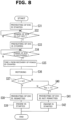
- Fig. 8 shows a flow chart of a third embodiment
- Fig. 7 shows a system configuration of the internal combustion engine 1 according to the third embodiment.
- the third embodiment is applied to the internal combustion engine 1 that drives a generator 21 as a so-called series hybrid vehicle.
- driving wheels are driven by a travelling motor (not shown), and the internal combustion engine 1 is used for power generation.
- a temperature sensor 22 for detecting temperature of the gas that passes through the electric heating catalyst 5 is set at a downstream side (an outlet side) of the electric heating catalyst 5.
- the temperature sensor 22 is set in the vicinity of a boundary between the upstream-side electric heating catalyst 5 and the downstream-side catalyst 6 in the casing of the pre-catalyst 3.
- a detection value according to the temperature of the electric heating catalyst 5 is measured by the temperature sensor 22. Therefore, while the gas is flowing, the temperature of the electric heating catalyst 5 can be substantially detected by the temperature sensor 22.
- steps S31 to S35 are the same as steps S1 to S5 of the first embodiment.
- the energization of the electric heating catalyst 5 is started, that is, the preheating of the electric heating catalyst 5 is started (step S31).
- step S33 When the power of the engine controller 8 is cut off, the energization of the electric heating catalyst 5 is stopped by and according to this cut-off (step S33) . Afterwards, when the power of the engine controller 8 is recovered (step S34), the engine controller 8 starts to measure a timer t that measures an elapsed time from a time of this recovery of the power (step S35).
- motoring (rotating) of the internal combustion engine 1 is performed using the generator 21 (step S36).
- the generator 21 step S36.
- the engine controller 8 compares a value of the timer t with a threshold value tc3.
- the threshold value tc3 is appropriately set on the basis of the forcible cooling by the motoring.
- the value of the timer t i.e. the elapsed time from the recovery of the power
- the energization (the preheating) of the electric heating catalyst 5 is forbidden or stopped. If there is a start request of the internal combustion engine 1 during this period, as shown as step S42, the internal combustion engine 1 is started without preheating the electric heating catalyst 5.
- step S38 When the elapsed time t from the recovery of the power exceeds the threshold value tc3, as shown as step S38, the energization of the electric heating catalyst 5, i.e. the preheating of the electric heating catalyst 5, is performed as usual. That is, the preheating from an initial state in which the electric heating catalyst 5 is regarded as being in a cold state is performed again. Then, the internal combustion engine 1 is started by and according to the start request of the internal combustion engine 1 (step S39).
- the engine controller 8 further compares a temperature Tec of the electric heating catalyst 5 detected by the temperature sensor 22 with a threshold temperature T1. Then, when the temperature Tec of the electric heating catalyst 5 is equal to or less than the threshold temperature T1 while the elapsed time t is the threshold value tc3 or less, resumption of the preheating is permitted.
- the cooling period which is the waiting time until the preheating is resumed, can be shorter than the case of the natural cooling (the self-cooling) .
- the threshold value tc3 of the elapsed time t is fixedly set, which is similar to the first embodiment.
- the threshold value tc3 could be variably set according to the change amount ⁇ SOC of the SOC.
- this third embodiment can be applied to not only the series hybrid vehicle, but also a vehicle as long as this vehicle has a configuration in which the internal combustion engine 1 can be driven by any external drive source.
- Fig. 10 shows a flow chart of a fourth embodiment
- Fig. 9 shows a system configuration of the internal combustion engine 1 according to the fourth embodiment.
- a secondary air pump 31 that can supply secondary air to the electric heating catalyst 5 in the exhaust passage 2 is provided.
- the secondary air pump 31 is connected to the exhaust passage 2 at an upstream side of the electric heating catalyst 5 through a secondary air passage 31a.
- a temperature sensor 22 for detecting temperature of the gas that passes through the electric heating catalyst 5 is set at a downstream side (an outlet side) of the electric heating catalyst 5.
- the temperature sensor 22 is set in the vicinity of a boundary between the upstream-side electric heating catalyst 5 and the downstream-side catalyst 6 in the casing of the pre-catalyst 3. The secondary air flows through the pre-catalyst 3, then, similar to the third embodiment, the temperature of the electric heating catalyst 5 can be substantially detected by the temperature sensor 22.
- the flow chart in Fig. 10 is the same as the flow chart in Fig. 8 of the third embodiment except for step S56. That is, when it is detected that the driver's seat door has been opened, the energization of the electric heating catalyst 5 is started, that is, the preheating of the electric heating catalyst 5 is started (step S51) . Subsequently, a judgment is made as to whether or not an event in which the power of the engine controller 8 is lost (cut off) has occurred (step S52).
- step S53 When the power of the engine controller 8 is cut off, the energization of the electric heating catalyst 5 is stopped by and according to this cut-off (step S53) . Afterwards, when the power of the engine controller 8 is recovered (step S54), the engine controller 8 starts to measure a timer t that measures an elapsed time from a time of this recovery of the power (step S55).
- the secondary air pump 31 is operated (step S56) .
- the gas flows through the electric heating catalyst 5, then the forcible cooling is carried out.
- the engine controller 8 compares a value of the timer t with a threshold value tc4.
- the threshold value tc4 is appropriately set on the basis of the forcible cooling by the supply of the secondary air.
- the value of the timer t i.e. the elapsed time from the recovery of the power
- the threshold value tc4 or less as shown as step S51, the energization (the preheating) of the electric heating catalyst 5 is forbidden or stopped. If there is a start request of the internal combustion engine 1 during this period, as shown as step S52, the internal combustion engine 1 is started without preheating the electric heating catalyst 5.
- step S58 When the elapsed time t from the recovery of the power exceeds the threshold value tc4, as shown as step S58, the energization of the electric heating catalyst 5, i.e. the preheating of the electric heating catalyst 5, is performed as usual. That is, the preheating from an initial state in which the electric heating catalyst 5 is regarded as being in a cold state is performed again. Then, the internal combustion engine 1 is started by and according to the start request of the internal combustion engine 1 (step S59).
- the engine controller 8 further compares a temperature Tec of the electric heating catalyst 5 detected by the temperature sensor 22 with a threshold temperature T1. Then, when the temperature Tec of the electric heating catalyst 5 is equal to or less than the threshold temperature T1 while the elapsed time t is the threshold value tc4 or less, resumption of the preheating is permitted.
- the cooling period which is the waiting time until the preheating is resumed, can be shorter than the case of the natural cooling (the self-cooling).
- the threshold value tc4 of the elapsed time t is fixedly set, which is similar to the first embodiment.
- the threshold value tc4 could be variably set according to the change amount ⁇ SOC of the SOC.
Landscapes
- Engineering & Computer Science (AREA)
- Chemical & Material Sciences (AREA)
- Chemical Kinetics & Catalysis (AREA)
- Combustion & Propulsion (AREA)
- Mechanical Engineering (AREA)
- General Engineering & Computer Science (AREA)
- Health & Medical Sciences (AREA)
- Toxicology (AREA)
- Exhaust Gas After Treatment (AREA)
Applications Claiming Priority (1)
| Application Number | Priority Date | Filing Date | Title |
|---|---|---|---|
| PCT/IB2020/000511 WO2021240189A1 (ja) | 2020-05-28 | 2020-05-28 | 内燃機関の制御方法および制御装置 |
Publications (3)
| Publication Number | Publication Date |
|---|---|
| EP4159983A1 true EP4159983A1 (de) | 2023-04-05 |
| EP4159983A4 EP4159983A4 (de) | 2023-04-05 |
| EP4159983B1 EP4159983B1 (de) | 2024-03-13 |
Family
ID=78723018
Family Applications (1)
| Application Number | Title | Priority Date | Filing Date |
|---|---|---|---|
| EP20937685.4A Active EP4159983B1 (de) | 2020-05-28 | 2020-05-28 | Steuerungsverfahren und steuerungsvorrichtung für einen verbrennungsmotor |
Country Status (5)
| Country | Link |
|---|---|
| US (1) | US11788451B2 (de) |
| EP (1) | EP4159983B1 (de) |
| JP (1) | JP7409498B2 (de) |
| CN (1) | CN115667681B (de) |
| WO (1) | WO2021240189A1 (de) |
Families Citing this family (1)
| Publication number | Priority date | Publication date | Assignee | Title |
|---|---|---|---|---|
| US11739671B2 (en) * | 2021-04-28 | 2023-08-29 | Ford Global Technologies, Llc | Systems and methods for providing a heating cycle to an after-treatment system of a vehicle |
Family Cites Families (9)
| Publication number | Priority date | Publication date | Assignee | Title |
|---|---|---|---|---|
| JP2007321719A (ja) * | 2006-06-05 | 2007-12-13 | Mazda Motor Corp | 排気ガス浄化用触媒予熱方法及び同装置 |
| JP4983614B2 (ja) * | 2008-01-15 | 2012-07-25 | トヨタ自動車株式会社 | 電気加熱式触媒の制御装置及び方法 |
| JP2011196231A (ja) * | 2010-03-18 | 2011-10-06 | Toyota Motor Corp | 内燃機関の触媒ヒータ制御装置 |
| CN103339353B (zh) * | 2011-02-01 | 2015-08-12 | 丰田自动车株式会社 | 车辆及催化装置的温度控制方法 |
| JP2015017502A (ja) * | 2013-07-08 | 2015-01-29 | トヨタ自動車株式会社 | ハイブリッド車両の制御装置 |
| JP2015075068A (ja) | 2013-10-11 | 2015-04-20 | トヨタ自動車株式会社 | 車両の制御装置 |
| JP6304090B2 (ja) * | 2015-03-24 | 2018-04-04 | トヨタ自動車株式会社 | ハイブリッド車両の駆動装置 |
| JP6791096B2 (ja) * | 2017-10-24 | 2020-11-25 | 株式会社デンソー | 車両の排気浄化システムの制御装置および制御方法 |
| JP6958484B2 (ja) * | 2018-05-29 | 2021-11-02 | トヨタ自動車株式会社 | 車両用制御装置 |
-
2020
- 2020-05-28 US US17/926,689 patent/US11788451B2/en active Active
- 2020-05-28 JP JP2022526528A patent/JP7409498B2/ja active Active
- 2020-05-28 WO PCT/IB2020/000511 patent/WO2021240189A1/ja not_active Ceased
- 2020-05-28 EP EP20937685.4A patent/EP4159983B1/de active Active
- 2020-05-28 CN CN202080101385.4A patent/CN115667681B/zh active Active
Also Published As
| Publication number | Publication date |
|---|---|
| WO2021240189A1 (ja) | 2021-12-02 |
| CN115667681B (zh) | 2025-04-11 |
| EP4159983B1 (de) | 2024-03-13 |
| CN115667681A (zh) | 2023-01-31 |
| US20230193799A1 (en) | 2023-06-22 |
| JP7409498B2 (ja) | 2024-01-09 |
| JPWO2021240189A1 (de) | 2021-12-02 |
| US11788451B2 (en) | 2023-10-17 |
Similar Documents
| Publication | Publication Date | Title |
|---|---|---|
| US5904902A (en) | Exhaust purifier for internal combustion engine | |
| US8312712B2 (en) | Electrically heated particulate filter regeneration during engine start/stop operation | |
| US7558668B2 (en) | Exhaust system having temperature sensor verification | |
| EP1096126A2 (de) | Gerät und Methode zur Auspuffheizung für einen Verbrennungsmotor | |
| CN110182198B (zh) | 混合动力车辆的控制装置 | |
| JP2000240434A (ja) | 内燃機関の排気2次空気供給制御装置 | |
| JPH08220059A (ja) | 空燃比センサのヒータ制御装置 | |
| EP4159983B1 (de) | Steuerungsverfahren und steuerungsvorrichtung für einen verbrennungsmotor | |
| US7249456B2 (en) | Method of controlling a heating device of a particle filter | |
| US11624303B1 (en) | Deceleration fuel cut-off enabled regeneration for gas particulate filter | |
| KR102734761B1 (ko) | 48v 마일드 하이브리드 차량의 ehc 히팅 제어 방법 및 시스템 | |
| JP2867776B2 (ja) | 内燃機関の排ガス浄化装置 | |
| JP2630024B2 (ja) | エンジンの排気浄化装置 | |
| EP4378776A1 (de) | Verfahren und vorrichtung zur steuerung des starts und stopps eines verbrennungsmotors in einem hybridfahrzeug | |
| JPH09158718A (ja) | 電気加熱式触媒の通電制御装置 | |
| JPH06173663A (ja) | 内燃機関の排気浄化装置 | |
| RU2068108C1 (ru) | Способ управления функционированием двигателя внутреннего сгорания, система управления для двигателя внутреннего сгорания | |
| JP2000170520A (ja) | 内燃機関のパティキュレート除去システム | |
| JPH0711942A (ja) | 通電加熱式触媒コンバータ | |
| JP2833376B2 (ja) | 電熱触媒の通電制御装置 | |
| JP3282310B2 (ja) | ディーゼルエンジンの排気後処理装置 | |
| JPH0925814A (ja) | エンジンの排気浄化装置 | |
| JP2598577Y2 (ja) | パティキュレート・トラップ装置 | |
| JP2000097015A (ja) | 排気浄化装置の故障検出装置 | |
| JP3371058B2 (ja) | エンジン回転数制御装置 |
Legal Events
| Date | Code | Title | Description |
|---|---|---|---|
| STAA | Information on the status of an ep patent application or granted ep patent |
Free format text: STATUS: THE INTERNATIONAL PUBLICATION HAS BEEN MADE |
|
| PUAI | Public reference made under article 153(3) epc to a published international application that has entered the european phase |
Free format text: ORIGINAL CODE: 0009012 |
|
| STAA | Information on the status of an ep patent application or granted ep patent |
Free format text: STATUS: REQUEST FOR EXAMINATION WAS MADE |
|
| 17P | Request for examination filed |
Effective date: 20221130 |
|
| A4 | Supplementary search report drawn up and despatched |
Effective date: 20230306 |
|
| AK | Designated contracting states |
Kind code of ref document: A1 Designated state(s): AL AT BE BG CH CY CZ DE DK EE ES FI FR GB GR HR HU IE IS IT LI LT LU LV MC MK MT NL NO PL PT RO RS SE SI SK SM TR |
|
| STAA | Information on the status of an ep patent application or granted ep patent |
Free format text: STATUS: EXAMINATION IS IN PROGRESS |
|
| 17Q | First examination report despatched |
Effective date: 20230606 |
|
| DAV | Request for validation of the european patent (deleted) | ||
| DAX | Request for extension of the european patent (deleted) | ||
| GRAP | Despatch of communication of intention to grant a patent |
Free format text: ORIGINAL CODE: EPIDOSNIGR1 |
|
| STAA | Information on the status of an ep patent application or granted ep patent |
Free format text: STATUS: GRANT OF PATENT IS INTENDED |
|
| INTG | Intention to grant announced |
Effective date: 20231222 |
|
| RAP3 | Party data changed (applicant data changed or rights of an application transferred) |
Owner name: NISSAN MOTOR CO., LTD. Owner name: RENAULT S.A.S. |
|
| GRAS | Grant fee paid |
Free format text: ORIGINAL CODE: EPIDOSNIGR3 |
|
| GRAA | (expected) grant |
Free format text: ORIGINAL CODE: 0009210 |
|
| STAA | Information on the status of an ep patent application or granted ep patent |
Free format text: STATUS: THE PATENT HAS BEEN GRANTED |
|
| AK | Designated contracting states |
Kind code of ref document: B1 Designated state(s): AL AT BE BG CH CY CZ DE DK EE ES FI FR GB GR HR HU IE IS IT LI LT LU LV MC MK MT NL NO PL PT RO RS SE SI SK SM TR |
|
| RAP3 | Party data changed (applicant data changed or rights of an application transferred) |
Owner name: RENAULT S.A.S. Owner name: NISSAN MOTOR CO., LTD. |
|
| REG | Reference to a national code |
Ref country code: GB Ref legal event code: FG4D |
|
| REG | Reference to a national code |
Ref country code: CH Ref legal event code: EP |
|
| REG | Reference to a national code |
Ref country code: DE Ref legal event code: R096 Ref document number: 602020027369 Country of ref document: DE |
|
| REG | Reference to a national code |
Ref country code: IE Ref legal event code: FG4D |
|
| PG25 | Lapsed in a contracting state [announced via postgrant information from national office to epo] |
Ref country code: LT Free format text: LAPSE BECAUSE OF FAILURE TO SUBMIT A TRANSLATION OF THE DESCRIPTION OR TO PAY THE FEE WITHIN THE PRESCRIBED TIME-LIMIT Effective date: 20240313 |
|
| REG | Reference to a national code |
Ref country code: LT Ref legal event code: MG9D |
|
| PG25 | Lapsed in a contracting state [announced via postgrant information from national office to epo] |
Ref country code: GR Free format text: LAPSE BECAUSE OF FAILURE TO SUBMIT A TRANSLATION OF THE DESCRIPTION OR TO PAY THE FEE WITHIN THE PRESCRIBED TIME-LIMIT Effective date: 20240614 |
|
| REG | Reference to a national code |
Ref country code: NL Ref legal event code: MP Effective date: 20240313 |
|
| PG25 | Lapsed in a contracting state [announced via postgrant information from national office to epo] |
Ref country code: HR Free format text: LAPSE BECAUSE OF FAILURE TO SUBMIT A TRANSLATION OF THE DESCRIPTION OR TO PAY THE FEE WITHIN THE PRESCRIBED TIME-LIMIT Effective date: 20240313 Ref country code: RS Free format text: LAPSE BECAUSE OF FAILURE TO SUBMIT A TRANSLATION OF THE DESCRIPTION OR TO PAY THE FEE WITHIN THE PRESCRIBED TIME-LIMIT Effective date: 20240613 |
|
| PG25 | Lapsed in a contracting state [announced via postgrant information from national office to epo] |
Ref country code: ES Free format text: LAPSE BECAUSE OF FAILURE TO SUBMIT A TRANSLATION OF THE DESCRIPTION OR TO PAY THE FEE WITHIN THE PRESCRIBED TIME-LIMIT Effective date: 20240313 |
|
| PG25 | Lapsed in a contracting state [announced via postgrant information from national office to epo] |
Ref country code: RS Free format text: LAPSE BECAUSE OF FAILURE TO SUBMIT A TRANSLATION OF THE DESCRIPTION OR TO PAY THE FEE WITHIN THE PRESCRIBED TIME-LIMIT Effective date: 20240613 Ref country code: NO Free format text: LAPSE BECAUSE OF FAILURE TO SUBMIT A TRANSLATION OF THE DESCRIPTION OR TO PAY THE FEE WITHIN THE PRESCRIBED TIME-LIMIT Effective date: 20240613 Ref country code: LT Free format text: LAPSE BECAUSE OF FAILURE TO SUBMIT A TRANSLATION OF THE DESCRIPTION OR TO PAY THE FEE WITHIN THE PRESCRIBED TIME-LIMIT Effective date: 20240313 Ref country code: HR Free format text: LAPSE BECAUSE OF FAILURE TO SUBMIT A TRANSLATION OF THE DESCRIPTION OR TO PAY THE FEE WITHIN THE PRESCRIBED TIME-LIMIT Effective date: 20240313 Ref country code: GR Free format text: LAPSE BECAUSE OF FAILURE TO SUBMIT A TRANSLATION OF THE DESCRIPTION OR TO PAY THE FEE WITHIN THE PRESCRIBED TIME-LIMIT Effective date: 20240614 Ref country code: FI Free format text: LAPSE BECAUSE OF FAILURE TO SUBMIT A TRANSLATION OF THE DESCRIPTION OR TO PAY THE FEE WITHIN THE PRESCRIBED TIME-LIMIT Effective date: 20240313 Ref country code: ES Free format text: LAPSE BECAUSE OF FAILURE TO SUBMIT A TRANSLATION OF THE DESCRIPTION OR TO PAY THE FEE WITHIN THE PRESCRIBED TIME-LIMIT Effective date: 20240313 Ref country code: BG Free format text: LAPSE BECAUSE OF FAILURE TO SUBMIT A TRANSLATION OF THE DESCRIPTION OR TO PAY THE FEE WITHIN THE PRESCRIBED TIME-LIMIT Effective date: 20240313 |
|
| REG | Reference to a national code |
Ref country code: AT Ref legal event code: MK05 Ref document number: 1665953 Country of ref document: AT Kind code of ref document: T Effective date: 20240313 |
|
| PG25 | Lapsed in a contracting state [announced via postgrant information from national office to epo] |
Ref country code: SE Free format text: LAPSE BECAUSE OF FAILURE TO SUBMIT A TRANSLATION OF THE DESCRIPTION OR TO PAY THE FEE WITHIN THE PRESCRIBED TIME-LIMIT Effective date: 20240313 Ref country code: LV Free format text: LAPSE BECAUSE OF FAILURE TO SUBMIT A TRANSLATION OF THE DESCRIPTION OR TO PAY THE FEE WITHIN THE PRESCRIBED TIME-LIMIT Effective date: 20240313 |
|
| PG25 | Lapsed in a contracting state [announced via postgrant information from national office to epo] |
Ref country code: NL Free format text: LAPSE BECAUSE OF FAILURE TO SUBMIT A TRANSLATION OF THE DESCRIPTION OR TO PAY THE FEE WITHIN THE PRESCRIBED TIME-LIMIT Effective date: 20240313 |
|
| PG25 | Lapsed in a contracting state [announced via postgrant information from national office to epo] |
Ref country code: NL Free format text: LAPSE BECAUSE OF FAILURE TO SUBMIT A TRANSLATION OF THE DESCRIPTION OR TO PAY THE FEE WITHIN THE PRESCRIBED TIME-LIMIT Effective date: 20240313 |
|
| PG25 | Lapsed in a contracting state [announced via postgrant information from national office to epo] |
Ref country code: IS Free format text: LAPSE BECAUSE OF FAILURE TO SUBMIT A TRANSLATION OF THE DESCRIPTION OR TO PAY THE FEE WITHIN THE PRESCRIBED TIME-LIMIT Effective date: 20240713 |
|
| PG25 | Lapsed in a contracting state [announced via postgrant information from national office to epo] |
Ref country code: PT Free format text: LAPSE BECAUSE OF FAILURE TO SUBMIT A TRANSLATION OF THE DESCRIPTION OR TO PAY THE FEE WITHIN THE PRESCRIBED TIME-LIMIT Effective date: 20240715 Ref country code: SM Free format text: LAPSE BECAUSE OF FAILURE TO SUBMIT A TRANSLATION OF THE DESCRIPTION OR TO PAY THE FEE WITHIN THE PRESCRIBED TIME-LIMIT Effective date: 20240313 |
|
| PG25 | Lapsed in a contracting state [announced via postgrant information from national office to epo] |
Ref country code: EE Free format text: LAPSE BECAUSE OF FAILURE TO SUBMIT A TRANSLATION OF THE DESCRIPTION OR TO PAY THE FEE WITHIN THE PRESCRIBED TIME-LIMIT Effective date: 20240313 Ref country code: CZ Free format text: LAPSE BECAUSE OF FAILURE TO SUBMIT A TRANSLATION OF THE DESCRIPTION OR TO PAY THE FEE WITHIN THE PRESCRIBED TIME-LIMIT Effective date: 20240313 |
|
| PG25 | Lapsed in a contracting state [announced via postgrant information from national office to epo] |
Ref country code: AT Free format text: LAPSE BECAUSE OF FAILURE TO SUBMIT A TRANSLATION OF THE DESCRIPTION OR TO PAY THE FEE WITHIN THE PRESCRIBED TIME-LIMIT Effective date: 20240313 |
|
| PG25 | Lapsed in a contracting state [announced via postgrant information from national office to epo] |
Ref country code: PL Free format text: LAPSE BECAUSE OF FAILURE TO SUBMIT A TRANSLATION OF THE DESCRIPTION OR TO PAY THE FEE WITHIN THE PRESCRIBED TIME-LIMIT Effective date: 20240313 |
|
| PG25 | Lapsed in a contracting state [announced via postgrant information from national office to epo] |
Ref country code: SK Free format text: LAPSE BECAUSE OF FAILURE TO SUBMIT A TRANSLATION OF THE DESCRIPTION OR TO PAY THE FEE WITHIN THE PRESCRIBED TIME-LIMIT Effective date: 20240313 |
|
| PG25 | Lapsed in a contracting state [announced via postgrant information from national office to epo] |
Ref country code: SM Free format text: LAPSE BECAUSE OF FAILURE TO SUBMIT A TRANSLATION OF THE DESCRIPTION OR TO PAY THE FEE WITHIN THE PRESCRIBED TIME-LIMIT Effective date: 20240313 Ref country code: SK Free format text: LAPSE BECAUSE OF FAILURE TO SUBMIT A TRANSLATION OF THE DESCRIPTION OR TO PAY THE FEE WITHIN THE PRESCRIBED TIME-LIMIT Effective date: 20240313 Ref country code: RO Free format text: LAPSE BECAUSE OF FAILURE TO SUBMIT A TRANSLATION OF THE DESCRIPTION OR TO PAY THE FEE WITHIN THE PRESCRIBED TIME-LIMIT Effective date: 20240313 Ref country code: PT Free format text: LAPSE BECAUSE OF FAILURE TO SUBMIT A TRANSLATION OF THE DESCRIPTION OR TO PAY THE FEE WITHIN THE PRESCRIBED TIME-LIMIT Effective date: 20240715 Ref country code: PL Free format text: LAPSE BECAUSE OF FAILURE TO SUBMIT A TRANSLATION OF THE DESCRIPTION OR TO PAY THE FEE WITHIN THE PRESCRIBED TIME-LIMIT Effective date: 20240313 Ref country code: IS Free format text: LAPSE BECAUSE OF FAILURE TO SUBMIT A TRANSLATION OF THE DESCRIPTION OR TO PAY THE FEE WITHIN THE PRESCRIBED TIME-LIMIT Effective date: 20240713 Ref country code: EE Free format text: LAPSE BECAUSE OF FAILURE TO SUBMIT A TRANSLATION OF THE DESCRIPTION OR TO PAY THE FEE WITHIN THE PRESCRIBED TIME-LIMIT Effective date: 20240313 Ref country code: CZ Free format text: LAPSE BECAUSE OF FAILURE TO SUBMIT A TRANSLATION OF THE DESCRIPTION OR TO PAY THE FEE WITHIN THE PRESCRIBED TIME-LIMIT Effective date: 20240313 Ref country code: AT Free format text: LAPSE BECAUSE OF FAILURE TO SUBMIT A TRANSLATION OF THE DESCRIPTION OR TO PAY THE FEE WITHIN THE PRESCRIBED TIME-LIMIT Effective date: 20240313 |
|
| PG25 | Lapsed in a contracting state [announced via postgrant information from national office to epo] |
Ref country code: IT Free format text: LAPSE BECAUSE OF FAILURE TO SUBMIT A TRANSLATION OF THE DESCRIPTION OR TO PAY THE FEE WITHIN THE PRESCRIBED TIME-LIMIT Effective date: 20240313 |
|
| REG | Reference to a national code |
Ref country code: DE Ref legal event code: R097 Ref document number: 602020027369 Country of ref document: DE |
|
| REG | Reference to a national code |
Ref country code: CH Ref legal event code: PL |
|
| PG25 | Lapsed in a contracting state [announced via postgrant information from national office to epo] |
Ref country code: IT Free format text: LAPSE BECAUSE OF FAILURE TO SUBMIT A TRANSLATION OF THE DESCRIPTION OR TO PAY THE FEE WITHIN THE PRESCRIBED TIME-LIMIT Effective date: 20240313 |
|
| PG25 | Lapsed in a contracting state [announced via postgrant information from national office to epo] |
Ref country code: MC Free format text: LAPSE BECAUSE OF FAILURE TO SUBMIT A TRANSLATION OF THE DESCRIPTION OR TO PAY THE FEE WITHIN THE PRESCRIBED TIME-LIMIT Effective date: 20240313 |
|
| PG25 | Lapsed in a contracting state [announced via postgrant information from national office to epo] |
Ref country code: DK Free format text: LAPSE BECAUSE OF FAILURE TO SUBMIT A TRANSLATION OF THE DESCRIPTION OR TO PAY THE FEE WITHIN THE PRESCRIBED TIME-LIMIT Effective date: 20240313 |
|
| PG25 | Lapsed in a contracting state [announced via postgrant information from national office to epo] |
Ref country code: LU Free format text: LAPSE BECAUSE OF NON-PAYMENT OF DUE FEES Effective date: 20240528 |
|
| PLBE | No opposition filed within time limit |
Free format text: ORIGINAL CODE: 0009261 |
|
| STAA | Information on the status of an ep patent application or granted ep patent |
Free format text: STATUS: NO OPPOSITION FILED WITHIN TIME LIMIT |
|
| PG25 | Lapsed in a contracting state [announced via postgrant information from national office to epo] |
Ref country code: MC Free format text: LAPSE BECAUSE OF FAILURE TO SUBMIT A TRANSLATION OF THE DESCRIPTION OR TO PAY THE FEE WITHIN THE PRESCRIBED TIME-LIMIT Effective date: 20240313 Ref country code: LU Free format text: LAPSE BECAUSE OF NON-PAYMENT OF DUE FEES Effective date: 20240528 Ref country code: DK Free format text: LAPSE BECAUSE OF FAILURE TO SUBMIT A TRANSLATION OF THE DESCRIPTION OR TO PAY THE FEE WITHIN THE PRESCRIBED TIME-LIMIT Effective date: 20240313 Ref country code: CH Free format text: LAPSE BECAUSE OF NON-PAYMENT OF DUE FEES Effective date: 20240531 |
|
| 26N | No opposition filed |
Effective date: 20241216 |
|
| REG | Reference to a national code |
Ref country code: BE Ref legal event code: MM Effective date: 20240531 |
|
| PG25 | Lapsed in a contracting state [announced via postgrant information from national office to epo] |
Ref country code: IE Free format text: LAPSE BECAUSE OF NON-PAYMENT OF DUE FEES Effective date: 20240528 |
|
| PG25 | Lapsed in a contracting state [announced via postgrant information from national office to epo] |
Ref country code: SI Free format text: LAPSE BECAUSE OF FAILURE TO SUBMIT A TRANSLATION OF THE DESCRIPTION OR TO PAY THE FEE WITHIN THE PRESCRIBED TIME-LIMIT Effective date: 20240313 Ref country code: BE Free format text: LAPSE BECAUSE OF NON-PAYMENT OF DUE FEES Effective date: 20240531 |
|
| PGFP | Annual fee paid to national office [announced via postgrant information from national office to epo] |
Ref country code: DE Payment date: 20250423 Year of fee payment: 6 |
|
| PGFP | Annual fee paid to national office [announced via postgrant information from national office to epo] |
Ref country code: GB Payment date: 20250423 Year of fee payment: 6 |
|
| PGFP | Annual fee paid to national office [announced via postgrant information from national office to epo] |
Ref country code: FR Payment date: 20250423 Year of fee payment: 6 |
|
| PG25 | Lapsed in a contracting state [announced via postgrant information from national office to epo] |
Ref country code: CY Free format text: LAPSE BECAUSE OF FAILURE TO SUBMIT A TRANSLATION OF THE DESCRIPTION OR TO PAY THE FEE WITHIN THE PRESCRIBED TIME-LIMIT; INVALID AB INITIO Effective date: 20200528 |
|
| PG25 | Lapsed in a contracting state [announced via postgrant information from national office to epo] |
Ref country code: HU Free format text: LAPSE BECAUSE OF FAILURE TO SUBMIT A TRANSLATION OF THE DESCRIPTION OR TO PAY THE FEE WITHIN THE PRESCRIBED TIME-LIMIT; INVALID AB INITIO Effective date: 20200528 |