EP4156982B1 - Fördereinrichtung für stabartikel und verfahren zum betrieb - Google Patents
Fördereinrichtung für stabartikel und verfahren zum betrieb Download PDFInfo
- Publication number
- EP4156982B1 EP4156982B1 EP21731071.3A EP21731071A EP4156982B1 EP 4156982 B1 EP4156982 B1 EP 4156982B1 EP 21731071 A EP21731071 A EP 21731071A EP 4156982 B1 EP4156982 B1 EP 4156982B1
- Authority
- EP
- European Patent Office
- Prior art keywords
- transfer element
- transfer
- bar
- groove
- article
- Prior art date
- Legal status (The legal status is an assumption and is not a legal conclusion. Google has not performed a legal analysis and makes no representation as to the accuracy of the status listed.)
- Active
Links
Images

Classifications
-
- A—HUMAN NECESSITIES
- A24—TOBACCO; CIGARS; CIGARETTES; SIMULATED SMOKING DEVICES; SMOKERS' REQUISITES
- A24C—MACHINES FOR MAKING CIGARS OR CIGARETTES
- A24C5/00—Making cigarettes; Making tipping materials for, or attaching filters or mouthpieces to, cigars or cigarettes
- A24C5/35—Adaptations of conveying apparatus for transporting cigarettes from making machine to packaging machine
-
- A—HUMAN NECESSITIES
- A24—TOBACCO; CIGARS; CIGARETTES; SIMULATED SMOKING DEVICES; SMOKERS' REQUISITES
- A24C—MACHINES FOR MAKING CIGARS OR CIGARETTES
- A24C5/00—Making cigarettes; Making tipping materials for, or attaching filters or mouthpieces to, cigars or cigarettes
- A24C5/32—Separating, ordering, counting or examining cigarettes; Regulating the feeding of tobacco according to rod or cigarette condition
- A24C5/322—Transporting cigarettes during manufacturing
- A24C5/325—Transporting cigarettes during manufacturing from a hopper
-
- A—HUMAN NECESSITIES
- A24—TOBACCO; CIGARS; CIGARETTES; SIMULATED SMOKING DEVICES; SMOKERS' REQUISITES
- A24C—MACHINES FOR MAKING CIGARS OR CIGARETTES
- A24C5/00—Making cigarettes; Making tipping materials for, or attaching filters or mouthpieces to, cigars or cigarettes
- A24C5/32—Separating, ordering, counting or examining cigarettes; Regulating the feeding of tobacco according to rod or cigarette condition
- A24C5/322—Transporting cigarettes during manufacturing
- A24C5/327—Construction details of the cigarette transport drum
-
- A—HUMAN NECESSITIES
- A24—TOBACCO; CIGARS; CIGARETTES; SIMULATED SMOKING DEVICES; SMOKERS' REQUISITES
- A24C—MACHINES FOR MAKING CIGARS OR CIGARETTES
- A24C5/00—Making cigarettes; Making tipping materials for, or attaching filters or mouthpieces to, cigars or cigarettes
- A24C5/47—Attaching filters or mouthpieces to cigars or cigarettes, e.g. inserting filters into cigarettes or their mouthpieces
- A24C5/478—Transport means for filter- or cigarette-rods in view of their assembling
-
- B—PERFORMING OPERATIONS; TRANSPORTING
- B65—CONVEYING; PACKING; STORING; HANDLING THIN OR FILAMENTARY MATERIAL
- B65G—TRANSPORT OR STORAGE DEVICES, e.g. CONVEYORS FOR LOADING OR TIPPING, SHOP CONVEYOR SYSTEMS OR PNEUMATIC TUBE CONVEYORS
- B65G47/00—Article or material-handling devices associated with conveyors; Methods employing such devices
- B65G47/02—Devices for feeding articles or materials to conveyors
- B65G47/04—Devices for feeding articles or materials to conveyors for feeding articles
- B65G47/12—Devices for feeding articles or materials to conveyors for feeding articles from disorderly-arranged article piles or from loose assemblages of articles
- B65G47/14—Devices for feeding articles or materials to conveyors for feeding articles from disorderly-arranged article piles or from loose assemblages of articles arranging or orientating the articles by mechanical or pneumatic means during feeding
- B65G47/1492—Devices for feeding articles or materials to conveyors for feeding articles from disorderly-arranged article piles or from loose assemblages of articles arranging or orientating the articles by mechanical or pneumatic means during feeding the articles being fed from a feeding conveyor
-
- B—PERFORMING OPERATIONS; TRANSPORTING
- B65—CONVEYING; PACKING; STORING; HANDLING THIN OR FILAMENTARY MATERIAL
- B65G—TRANSPORT OR STORAGE DEVICES, e.g. CONVEYORS FOR LOADING OR TIPPING, SHOP CONVEYOR SYSTEMS OR PNEUMATIC TUBE CONVEYORS
- B65G47/00—Article or material-handling devices associated with conveyors; Methods employing such devices
- B65G47/02—Devices for feeding articles or materials to conveyors
- B65G47/16—Devices for feeding articles or materials to conveyors for feeding materials in bulk
- B65G47/18—Arrangements or applications of hoppers or chutes
- B65G47/19—Arrangements or applications of hoppers or chutes having means for controlling material flow, e.g. to prevent overloading
-
- B—PERFORMING OPERATIONS; TRANSPORTING
- B65—CONVEYING; PACKING; STORING; HANDLING THIN OR FILAMENTARY MATERIAL
- B65G—TRANSPORT OR STORAGE DEVICES, e.g. CONVEYORS FOR LOADING OR TIPPING, SHOP CONVEYOR SYSTEMS OR PNEUMATIC TUBE CONVEYORS
- B65G47/00—Article or material-handling devices associated with conveyors; Methods employing such devices
- B65G47/74—Feeding, transfer, or discharging devices of particular kinds or types
- B65G47/84—Star-shaped wheels or devices having endless travelling belts or chains, the wheels or devices being equipped with article-engaging elements
- B65G47/846—Star-shaped wheels or wheels equipped with article-engaging elements
- B65G47/847—Star-shaped wheels or wheels equipped with article-engaging elements the article-engaging elements being grippers
-
- B—PERFORMING OPERATIONS; TRANSPORTING
- B65—CONVEYING; PACKING; STORING; HANDLING THIN OR FILAMENTARY MATERIAL
- B65G—TRANSPORT OR STORAGE DEVICES, e.g. CONVEYORS FOR LOADING OR TIPPING, SHOP CONVEYOR SYSTEMS OR PNEUMATIC TUBE CONVEYORS
- B65G47/00—Article or material-handling devices associated with conveyors; Methods employing such devices
- B65G47/74—Feeding, transfer, or discharging devices of particular kinds or types
- B65G47/84—Star-shaped wheels or devices having endless travelling belts or chains, the wheels or devices being equipped with article-engaging elements
- B65G47/846—Star-shaped wheels or wheels equipped with article-engaging elements
- B65G47/848—Star-shaped wheels or wheels equipped with article-engaging elements the article-engaging elements being suction or magnetic means
Definitions
- the present invention relates to a conveyor device for removing rod articles from an article storage device having the features of the preamble of claim 1, as well as a method for operating a conveyor device having the features of the preamble of claim 6.
- Stick articles can be, for example, stick-shaped smoking articles such as cigarettes, cigarillos, heat not burn products (HNB products) or similar products which are intended for inhalation by a consumer. In addition to or instead of tobacco, essential or medicinal substances can also be intended for inhalation. Stick articles also include preliminary products of smoking articles such as filter rods, tobacco sticks with a tobacco material that is shape-stabilized by a wrapping strip, segments of HNB products such as tubular cooling sections, flavor-influencing segments or the like, which are subsequently combined with other preliminary products to form a finished stick-shaped smoking article.
- HNB products heat not burn products
- Stick articles also include preliminary products of smoking articles such as filter rods, tobacco sticks with a tobacco material that is shape-stabilized by a wrapping strip, segments of HNB products such as tubular cooling sections, flavor-influencing segments or the like, which are subsequently combined with other preliminary products to form a finished stick-shaped smoking article.
- the rod articles are transported in conveyor systems at a very high transport speed and are manufactured and processed in very large quantities. They are fed into various points in the production process from a very large storage facility in a very large flow rate.
- the rod articles are stored in the storage facility in a stack with longitudinal axes aligned parallel to each other, whereby the rod articles are preferably aligned such that their end faces form planes aligned parallel to one another, and the stack thus has a thickness which corresponds to the length of the rod articles in the storage unit.
- the rod articles are transferred from the storage facility into the troughs of the central drum and transported away transversely to their longitudinal axes.
- the removal drum has a comparatively large diameter with a large number of troughs arranged in the outer surface, which are arranged at a very short distance, i.e. with a very small pitch.
- the central drum is driven at a comparatively low speed and a low peripheral speed of the troughs.
- the central drum has particularly deep troughs, or troughs with a wall that is enlarged on one side, so that the rod articles can be removed from the storage facility in a process-reliable manner.
- the supply of the rod articles from the storage to the central drum is effected by gravity in that the storage is arranged above the central drum and has an opening facing the central drum through which the rod articles exit in the direction of the central drum.
- a conveyor system is shown in the publication EP2999361B1 known; this has the features mentioned in the preamble of claim 1.
- Other conveyor devices from the prior art are known from DE1235206B and DE19546696C1 known.
- the invention is based on the object of creating a conveyor device and a method which improved promotion of bar items from an item store.
- the conveyor device for removing rod articles from an article storage is provided with at least one shaft for a single-row, cross-axial guidance of the rod articles.
- a rotatable transfer element with a groove for a rod article is arranged, which places the rod articles in troughs of a central drum for cross-axial removal.
- a rotatable insert wheel is provided, which is set up for an individual, cross-axial delivery of rod articles to the transfer element.
- the groove of the transfer element is set up to take over the rod articles delivered by the insert wheel and can be subjected to negative pressure. Rod articles delivered by the insert wheel can be held in the groove by means of negative pressure.
- the proposed solution enables particularly gentle removal from an article storage and conveying of bar articles onto a central drum by first effectively preventing any clamping or crushing of the cross-conveyed bar article during the separation process using the rotating insert wheel.
- the insert wheel also temporarily takes on a blocking function for those rod articles which are positioned in the product flow upstream of the individually, cross-conveyed rod article.
- the transfer element which can be subjected to negative pressure also ensures that the rod article is conveyed very gently and in particular is process-safe, as the transfer to the central drum can be controlled and monitored very precisely.
- the removal cam When conveyed using negative pressure on the transfer element, which can also be referred to as the removal cam, the rod article does not experience any grinding processes on the article surface, so that the load on the rod article is minimized.
- the service life of the machine parts is not reduced by grinding marks or wear and corresponding downtime.
- This measure is particularly effective in the area of the transfer element, as when rod articles are conveyed to a central drum, the rod articles have to be accelerated to the speed of the central drum, which can lead to high relative speeds with strong friction effects.
- the insert wheel is designed as a pair of insert wheels.
- This advantageous embodiment has two interacting insert wheels, between which rod articles are conveyed transversely and individually.
- the design of the insert wheel as a pair of insert wheels further reduces the risk of the rod article being conveyed becoming jammed or crushed, since a rigid wall for supporting the rod article against a single insert wheel can be dispensed with. This also reduces the load on the rod article and reduces unwanted grinding processes on the conveyor system.
- pivot pins and/or swing pins are arranged at the upper end of the at least one shaft.
- the pivot pins and/or swing pins are preferably arranged in the transition area between the article storage in which the rod articles are stored and the shaft for the single-row, cross-axial feed to the transfer element in order to improve the transition from a multi-row or multi-layer arrangement in the article storage to a single-row arrangement in the shaft.
- the transition to a single-row arrangement in the shaft can be made possible above all by a funnel-shaped design of the article storage towards the shaft.
- the pivot pins and/or swing pins are advantageously arranged at the end of this funnel-shaped design in order to further improve the gentle conveyance of the rod articles.
- the pivot pins are preferably actively driven. In alternative embodiments, passive pivot pins are also possible, which rotate according to the product pressure exerted.
- the oscillating bolts are actively operated and preferably oscillate at a frequency of 0.1 Hz to 100 Hz, more preferably from 20 Hz to 40 Hz. In preferred embodiments, the oscillation occurs around the longitudinal axis of the oscillating bolt, i.e. the axis around which the oscillating bolt oscillates is parallel to the main axes of the rod articles being conveyed.
- the transfer element is servo-driven.
- the drive of the transfer element by means of a servo motor enables precise and differentiated movement control of the transfer element, so that the The rod article can be removed, for example, at a significantly reduced rotation speed.
- removal can take place in the stationary position of the transfer element, ie the rotation speed is zero.
- the transfer to the central drum takes place synchronized with the speed of the central drum at the transfer point.
- the conveyor device has a plurality of shafts arranged next to one another, each with associated insert wheels and transfer elements for removing rod articles from the article storage and feeding them to the central drum.
- a parallel transfer of rod articles to the central drum can be carried out with the plurality of transfer elements, whereby the speed of the central drum can be increased and/or the load on the rod articles during conveyance to the central drum can be reduced.
- the transfer of rod articles from a transfer element can only be provided to every nth trough of the central drum, depending on the number n of shafts and associated transfer elements.
- the conveyor device has at least two shafts, which are filled with rod articles from the same article storage. Below the two shafts or downstream along the transport direction, two pairs of insert wheels are arranged, each with two insert wheels, which deliver individual, cross-conveyed rod articles to three transfer elements.
- the two transfer elements preferably have two different transfer positions on the central drum, with the individual transfer element in this In this embodiment, bar articles are only transferred to every second trough of the central drum.
- the distance between the takeover point downstream of the respective loading wheel on the respective transfer element and the respective transfer point for insertion into a trough of the central drum is greater than the distance between the pivot points of adjacent transfer elements.
- the groove of the transfer element can be subjected to overpressure for inserting the rod article into a trough in the central drum. This allows for improved control of the transfer from the transfer element to the central drum, since the holding of the rod article can be completed in a shorter period of time by applying negative pressure. In addition, the movement of the rod article from the transfer element to the central drum can be accelerated by applying overpressure.
- the process enables the rod articles to be removed from the shaft or shafts in a way that is gentle on the rod articles and at the same time ensures a high level of process reliability.
- the conveyor system is advantageously operated without collisions.
- the rotatable transfer element rotates completely. This means that the transfer element completes a complete circular movement with each transfer process of a rod article.
- the rotating transfer element oscillates.
- the transfer element makes two changes of direction with each transfer process and does not complete a complete circular movement.
- the transfer element moves from the takeover of the rod article to the transfer of the rod article to the central drum on the same path of movement as after the transfer to the central drum back to the takeover position in an orientation that faces the downstream opening of the shaft.
- Complete rotation is avoided, whereby the movement can be precisely controlled by means of a servo drive and the line for the application of negative pressure, if necessary negative pressure and positive pressure, is in the groove of the transfer element. can be carried out particularly easily.
- the distance between individual shafts of the conveyor system can be reduced, since the range of movement of the transfer element is smaller.
- all transfer elements under the majority of shafts are operated at the same conveying frequency.
- the conveying frequency can, for example, correspond to the rotational speed of the transfer elements.
- it is proposed that the transfer elements are operated with a working cycle that is offset from one another at the same conveying frequency.
- the rotational speed of the transfer element during transfer to the central drum is adapted to the rotational speed of the central drum, so that the peripheral speed in the groove and in the Trough at the transfer point are the same.
- the transfer element returns after a transfer to the central drum, temporarily higher rotation speeds than the maximum rotation speed during the transfer can be used, since in this case no bar article needs to be held.
- the groove is subjected to positive pressure for transfer into a trough in the central drum.
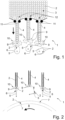
- pivot pins 11 are provided in the transition area of the funnel-shaped inlets 12 to the shafts 4, which prevent the rod articles 2 from jamming when moving to a single-row stacking and are therefore advantageous for gentle conveying of the rod articles 2.
- vibration pins 11 can also be provided instead of or in combination with the pivot pins 11, which have a comparable improvement in gentle conveying.
- Insertion wheels 9 are arranged at the downstream opening of each of the three shafts 4.
- the insertion wheels 9 can also referred to as a trough drum, and have recesses for rod articles 2 arranged closely together over the entire circumference.
- the insert wheels 9 below the shafts 4 are designed as a pair of insert wheels 10.
- a pair of insert wheels 10 comprises two insert wheels 9 which rotate synchronously in opposite directions so that rod articles 2 can be conveyed individually between the pair of insert wheels 9.
- the insert wheels 10 With the pair of insert wheels 10, no counterpressure is required in comparison to a surface that is not moving to the rod article 2 being conveyed, so that a particularly gentle separation with little friction on the rod article 2 can be achieved. Furthermore, the insert wheels 9 prevent product squashing and faulty separations.
- the pair of insert wheels 10 each delivers a single rod article 2 transversely to a transfer element 5, which is arranged downstream in relation to the product flow.
- the transfer elements 5 are arranged below the shafts 4, whereby the shafts 4 run in a straight line.
- the transfer element 5 arranged downstream of the opening of the shaft 4 has a groove 6 which can be subjected to negative pressure.
- the surface of the groove 6 of the transfer element 5 therefore has air-permeable areas via which a suction or suction air is connected, so that a rod article 2 can be the negative pressure between groove 6 and rod article 2 can be held in groove 6.
- the transfer element 5 rotates into a position facing the insert wheel pair 10 or takeover position.
- the groove 6 is thus directed against the transport direction or against the product flow in order to be able to take over the rod article 2 that is individually fed out by the insert wheel pair 10.
- the rod article 2 released by the two insert wheels 9 of the insert wheel pair 10 falls into the groove 6 of the transfer element 5, with the groove 6 being subjected to negative pressure in order to hold the rod article 2 in the groove 6.
- the transfer elements 5 then place the rod articles 2 into the troughs 7 of the continuously rotating central drum 7, which in the illustration of the Figure 1 is not shown.
- the Figure 2 shows the downstream area of the conveyor 1 with the central drum 7, whereby the article storage 3 is not shown for simplification.
- the article storage 3 is not shown for simplification.
- only one shaft 4 can be provided, each with an associated pair of insert wheels 10 and transfer element 5.
- the use of several shafts 4 enables the conveying capacity of the conveying device 1 to be adapted to the product flow conveyed by the central drum 7 and thus also to the throughput of a manufacturing machine for rod-shaped products.
- FIG. 2 In the presentation of the Figure 2 is a snapshot of operation with three transfer elements 5 in different phases or orientations.
- the left transfer element 5 has assumed an orientation facing the upstream insert wheel pair 10.
- the insert wheels 9 of the insert wheel pair 10 have already separated a bar article 2, but have not yet rotated far enough for the bar article 2 to be delivered.
- the delivery of the rod article 2 can be seen on the right-hand transfer element 5, whose working cycle is slightly earlier in comparison.
- the right-hand insert wheel pair 10 has already rotated further compared to the left-hand insert wheel pair 10, so that the rod article 2 is released or conveyed out. According to the arrangement, this falls out of the insert wheel pair 10 into the groove 6 of the transfer element 5, in which the rod article 2 is sucked in.
- the middle transfer element 5 in the Figure 2 has already progressed further in the sequence.
- the rod article 2 is held in the groove 6 subjected to negative pressure while the transfer element 5 has rotated clockwise.
- the rod article 2 is accordingly carried along and accelerated.
- no counter bearing is required to hold the rod article 2 in the groove 6 due to the negative pressure caused by the negative pressure connection in the groove 6 and the resulting holding force on the rod article 2.
- Figure 3 shows the section of the conveyor 1 from the Figure 2 at a time which is approximately half a working cycle of the transfer elements 5 later.
- the left and right transfer elements 5 each hold the rod article 2 from the Figure 2 and rotate towards the troughs 7 of the continuously rotating central drum 8.
- the right-hand transfer element 5 is located shortly before the transfer time and also before the transfer point to the trough 7 of the central drum 8.
- the transfer to the central drum 8 is synchronized, i.e. the groove 6 of the transfer element 5 and the trough 7 of the central drum 8 have a minimal distance at the transfer location or transfer point and their speeds are adjusted for the transfer time so that a reliable transfer of the rod article 2 can take place.
- the application of negative pressure in the groove 6 is released accordingly so that the rod article 2 is released and transferred to the trough 7 of the central drum 8, which conveys the rod article 2 on the central drum 8 transversely axially for further processing.
- the Figure 4 represents another snapshot of the section of conveyor 1, in which, compared to the Figure 2 approximately the time of one working cycle of the transfer elements 5 has passed.
- the middle transfer element 5 has transferred the rod article 2 to the trough 7, which is thus already behind the transfer point on the rotating central drum 8 and is being conveyed cross-axially on it.
- the other transfer elements 5 on the left and right are in this snapshot in a position that faces the respective insert wheel pair 10.
- the left insert wheel pair 10 has just released the rod article 2 so that it falls into the groove 6.
- the right transfer element 5 has the rod article 2 has already been taken over and is held in place by means of negative pressure.
- the transfer element 5 when it is aligned or positioned for the transfer of the rod article 2 to the insert wheel pair 10, has the lowest rotational speed during the work cycle. Whereas when the rod article 2 is transferred into the trough 7, the rotational speed reaches its maximum. The transfer element 5 accelerates as soon as the rod article 2 has been received in the groove 6, and decelerates again after the transfer. This is also evident in the overview of the Figures 2 and 4 which show approximately the same point in time in relation to the working cycle, with all transfer elements 5 of the conveyor device 1 preferably having the same working cycle duration.
- the left and right transfer elements 5 face the opening of the shaft 4 and only make a small angle change between the two snapshots.
- the middle transfer element 5 makes approximately a quarter turn between the two snapshots, since the transfer element 5 accelerates for the transfer to the central drum 8.
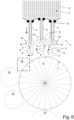
- the Figure 6 shows the embodiment of the Figure 1 with a central drum 8, onto which the rod articles 2 are conveyed transversely axially by the conveyor device 1.
- a transfer element 5 places a rod article 2 in accordance with the number n of shafts 4 into only every nth trough 7 on the central drum 8.
- the rod articles 2 conveyed cross-axially on the central drum 8 can be fed to various further processing steps.
- the rod articles 2 can be cut on the central drum 8, for example in a cutting area 13.
- the cut segments can then be staggered by satellite drums 14, whereby the segments of the rod articles 2 can also be pushed, which can be done by compressed air or by curve-controlled troughs.
- further processing steps can follow.
Landscapes
- Engineering & Computer Science (AREA)
- Mechanical Engineering (AREA)
- Specific Conveyance Elements (AREA)
- Feeding Of Articles To Conveyors (AREA)
Applications Claiming Priority (2)
| Application Number | Priority Date | Filing Date | Title |
|---|---|---|---|
| DE102020114600.0A DE102020114600A1 (de) | 2020-06-02 | 2020-06-02 | Fördereinrichtung für Stabartikel und Verfahren zum Betrieb |
| PCT/EP2021/064651 WO2021245067A1 (de) | 2020-06-02 | 2021-06-01 | Fördereinrichtung für stabartikel und verfahren zum betrieb |
Publications (2)
| Publication Number | Publication Date |
|---|---|
| EP4156982A1 EP4156982A1 (de) | 2023-04-05 |
| EP4156982B1 true EP4156982B1 (de) | 2024-08-28 |
Family
ID=76355457
Family Applications (1)
| Application Number | Title | Priority Date | Filing Date |
|---|---|---|---|
| EP21731071.3A Active EP4156982B1 (de) | 2020-06-02 | 2021-06-01 | Fördereinrichtung für stabartikel und verfahren zum betrieb |
Country Status (6)
| Country | Link |
|---|---|
| EP (1) | EP4156982B1 (pl) |
| KR (1) | KR20230018492A (pl) |
| CN (1) | CN115867154B (pl) |
| DE (1) | DE102020114600A1 (pl) |
| PL (1) | PL4156982T3 (pl) |
| WO (1) | WO2021245067A1 (pl) |
Citations (21)
| Publication number | Priority date | Publication date | Assignee | Title |
|---|---|---|---|---|
| GB392266A (en) | 1931-12-23 | 1933-05-18 | Imp Tobacco Co Ltd | Improvements in or relating to machinery for the manufacture of cigarettes |
| US2550616A (en) | 1949-09-12 | 1951-04-24 | Stephano Brothers | Feed drive for packaging machines |
| US2918197A (en) | 1955-04-29 | 1959-12-22 | Koerber & Co Kg | Conveyor apparatus |
| US2924356A (en) | 1954-07-21 | 1960-02-09 | Koerber & Co Kg | Cigarette magazine |
| US3067644A (en) | 1958-04-22 | 1962-12-11 | American Mach & Foundry | Mouthpiece feed |
| DE1177995B (de) | 1959-11-20 | 1964-09-10 | Tabak & Ind Masch | Vorrichtung zum Zufuehren von Zigaretten oder anderen stabfoermigen Gegenstaenden, vom Magazin in umlaufenden Nutentrommeln an Filtermundstueckzigarettenmaschinen |
| US4063633A (en) | 1976-11-10 | 1977-12-20 | Liggett Group Inc. | Vacuum plug feed machine |
| US4452255A (en) | 1981-04-25 | 1984-06-05 | Hauni-Werke Korber & Co. Kg. | Apparatus for transporting and classifying discrete articles of the tobacco processing industry |
| US4614263A (en) | 1983-09-13 | 1986-09-30 | Japan Tobacco, Inc. | Cigarette arranging apparatus |
| US4785928A (en) | 1985-05-18 | 1988-11-22 | Molins Plc | Feeding rod-like articles |
| US5114015A (en) | 1989-09-25 | 1992-05-19 | Fabriques De Tabac Reunies, S.A. | Delivery device and sorting machine for rod-like articles |
| EP0512492A1 (en) | 1991-05-08 | 1992-11-11 | Japan Tobacco Inc. | Cigarette supplying and stopping device used in a cigarette wrapping apparatus |
| DE19546696C1 (de) | 1995-12-14 | 1997-01-23 | Schmermund Maschf Alfred | Vorrichtung zum Zuführen von Zigaretten zu einer Zigarettenverpackungsmaschine |
| WO2002102176A1 (fr) | 2001-06-19 | 2002-12-27 | Japan Tobacco Inc. | Eliminateur d'objet de type barre |
| EP2517582A2 (de) | 2011-04-27 | 2012-10-31 | HAUNI Maschinenbau AG | Saugring für eine Fördertrommel der Tabak verarbeitenden Industrie |
| DE102013204381A1 (de) | 2013-03-13 | 2014-09-18 | Hauni Maschinenbau Ag | Transportvorrichtung zur Herstellung von stabförmigen Produkten der Tabak verarbeitenden Industrie |
| WO2014188306A1 (en) | 2013-05-21 | 2014-11-27 | G. D S.P.A. | Device for feeding rod-like smokers' articles in an automatic machine for the tobacco industry. |
| EP2868212A1 (de) | 2013-09-27 | 2015-05-06 | Hauni Maschinenbau AG | Transportvorrichtung zur Herstellung von stabförmigen Produkten der Tabak verarbeitenden Industrie |
| WO2015144532A1 (en) | 2014-03-25 | 2015-10-01 | British American Tobacco (Investments) Limited | Feed unit |
| WO2019105813A1 (en) | 2017-12-03 | 2019-06-06 | International Tobacco Machinery Poland Sp. Z O.O. | A replenishing device, an apparatus for manufacturing multisegment rods and a method for manufacturing multi-segment rods |
| EP3542650A2 (de) | 2018-03-22 | 2019-09-25 | Hauni Maschinenbau GmbH | Förder- und schneideinrichtung für stabförmige rauchartikel |
Family Cites Families (6)
| Publication number | Priority date | Publication date | Assignee | Title |
|---|---|---|---|---|
| DE102010010075B3 (de) * | 2010-02-25 | 2011-06-22 | Hauni Maschinenbau AG, 21033 | Vorrichtung und Verfahren zum Überführen stabförmiger Artikel der Tabak verarbeitenden Industrie aus einem Magazin in eine Förderleitung |
| DE102010020975A1 (de) * | 2010-05-14 | 2011-11-17 | Hauni Maschinenbau Ag | Anordnung und Verfahren zum Übernehmen von stabförmigen Artikeln der Tabak verarbeitenden Industrie von einem ersten Förderelement auf ein zweites Förderelement |
| DE102012216048A1 (de) * | 2012-09-11 | 2014-03-13 | Hauni Maschinenbau Ag | Fördertrommel der Tabak verarbeitenden Industrie |
| DE102012216857A1 (de) * | 2012-09-20 | 2014-03-20 | Hauni Maschinenbau Ag | Fördern von stabförmigen Artikeln der Tabak verarbeitenden Industrie |
| DE102014113296B3 (de) * | 2014-09-16 | 2015-07-16 | Hauni Maschinenbau Ag | Vorrichtung und Verfahren zur Übergabe stabförmiger Artikel der Tabak verarbeitenden Industrie von einem Längsförderer zur längsaxialen Förderung der Artikel auf einen Querförderer zur queraxialen Förderung der Artikel oder umgekehrt |
| DE102018106825A1 (de) * | 2018-03-22 | 2019-09-26 | Hauni Maschinenbau Gmbh | Fördereinrichtung für stabförmige Rauchartikel |
-
2020
- 2020-06-02 DE DE102020114600.0A patent/DE102020114600A1/de active Pending
-
2021
- 2021-06-01 EP EP21731071.3A patent/EP4156982B1/de active Active
- 2021-06-01 WO PCT/EP2021/064651 patent/WO2021245067A1/de not_active Ceased
- 2021-06-01 CN CN202180039581.8A patent/CN115867154B/zh active Active
- 2021-06-01 PL PL21731071.3T patent/PL4156982T3/pl unknown
- 2021-06-01 KR KR1020227046416A patent/KR20230018492A/ko active Pending
Patent Citations (21)
| Publication number | Priority date | Publication date | Assignee | Title |
|---|---|---|---|---|
| GB392266A (en) | 1931-12-23 | 1933-05-18 | Imp Tobacco Co Ltd | Improvements in or relating to machinery for the manufacture of cigarettes |
| US2550616A (en) | 1949-09-12 | 1951-04-24 | Stephano Brothers | Feed drive for packaging machines |
| US2924356A (en) | 1954-07-21 | 1960-02-09 | Koerber & Co Kg | Cigarette magazine |
| US2918197A (en) | 1955-04-29 | 1959-12-22 | Koerber & Co Kg | Conveyor apparatus |
| US3067644A (en) | 1958-04-22 | 1962-12-11 | American Mach & Foundry | Mouthpiece feed |
| DE1177995B (de) | 1959-11-20 | 1964-09-10 | Tabak & Ind Masch | Vorrichtung zum Zufuehren von Zigaretten oder anderen stabfoermigen Gegenstaenden, vom Magazin in umlaufenden Nutentrommeln an Filtermundstueckzigarettenmaschinen |
| US4063633A (en) | 1976-11-10 | 1977-12-20 | Liggett Group Inc. | Vacuum plug feed machine |
| US4452255A (en) | 1981-04-25 | 1984-06-05 | Hauni-Werke Korber & Co. Kg. | Apparatus for transporting and classifying discrete articles of the tobacco processing industry |
| US4614263A (en) | 1983-09-13 | 1986-09-30 | Japan Tobacco, Inc. | Cigarette arranging apparatus |
| US4785928A (en) | 1985-05-18 | 1988-11-22 | Molins Plc | Feeding rod-like articles |
| US5114015A (en) | 1989-09-25 | 1992-05-19 | Fabriques De Tabac Reunies, S.A. | Delivery device and sorting machine for rod-like articles |
| EP0512492A1 (en) | 1991-05-08 | 1992-11-11 | Japan Tobacco Inc. | Cigarette supplying and stopping device used in a cigarette wrapping apparatus |
| DE19546696C1 (de) | 1995-12-14 | 1997-01-23 | Schmermund Maschf Alfred | Vorrichtung zum Zuführen von Zigaretten zu einer Zigarettenverpackungsmaschine |
| WO2002102176A1 (fr) | 2001-06-19 | 2002-12-27 | Japan Tobacco Inc. | Eliminateur d'objet de type barre |
| EP2517582A2 (de) | 2011-04-27 | 2012-10-31 | HAUNI Maschinenbau AG | Saugring für eine Fördertrommel der Tabak verarbeitenden Industrie |
| DE102013204381A1 (de) | 2013-03-13 | 2014-09-18 | Hauni Maschinenbau Ag | Transportvorrichtung zur Herstellung von stabförmigen Produkten der Tabak verarbeitenden Industrie |
| WO2014188306A1 (en) | 2013-05-21 | 2014-11-27 | G. D S.P.A. | Device for feeding rod-like smokers' articles in an automatic machine for the tobacco industry. |
| EP2868212A1 (de) | 2013-09-27 | 2015-05-06 | Hauni Maschinenbau AG | Transportvorrichtung zur Herstellung von stabförmigen Produkten der Tabak verarbeitenden Industrie |
| WO2015144532A1 (en) | 2014-03-25 | 2015-10-01 | British American Tobacco (Investments) Limited | Feed unit |
| WO2019105813A1 (en) | 2017-12-03 | 2019-06-06 | International Tobacco Machinery Poland Sp. Z O.O. | A replenishing device, an apparatus for manufacturing multisegment rods and a method for manufacturing multi-segment rods |
| EP3542650A2 (de) | 2018-03-22 | 2019-09-25 | Hauni Maschinenbau GmbH | Förder- und schneideinrichtung für stabförmige rauchartikel |
Also Published As
| Publication number | Publication date |
|---|---|
| DE102020114600A1 (de) | 2021-12-02 |
| PL4156982T3 (pl) | 2025-02-03 |
| CN115867154A (zh) | 2023-03-28 |
| WO2021245067A1 (de) | 2021-12-09 |
| EP4156982A1 (de) | 2023-04-05 |
| KR20230018492A (ko) | 2023-02-07 |
| CN115867154B (zh) | 2025-03-18 |
Similar Documents
| Publication | Publication Date | Title |
|---|---|---|
| EP1525811B1 (de) | Vorrichtung und Verfahren zur Übergabe stabförmiger Artikel | |
| DE60311778T2 (de) | Zurückziehbare übergabeeinrichtung für eine dosiervorrichtung | |
| EP3053443B1 (de) | Wurstgruppierer und Verfahren zum Gruppieren von Würsten zu Wurstgruppen | |
| DE2618905A1 (de) | Foerdervorrichtung zum queraxialen foerdern stab- oder zylinderfoermiger gegenstaende | |
| EP1287753B1 (de) | Übertragungsvorrichtung und Verfahren zum Übertragen von Artikeln der tabakverarbeitenden Industrie | |
| EP3162739B1 (de) | Vorrichtung und verfahren zum übergeben von wurstportionen | |
| DE3641064A1 (de) | Foerdervorrichtung zum foerdern von einem doppelstrang abgetrennter stabfoermiger artikel der tabakverarbeitenden industrie | |
| EP3542650B1 (de) | Förder- und schneideinrichtung für stabförmige rauchartikel | |
| EP2364603A2 (de) | Tabakstrangmaschine zur Herstellung von Tabakstäben, Filteransetzmaschine zum Verbinden von Filtern mit Tabakstäben sowie Zigarettenherstellungsmaschine | |
| DE1481378C3 (de) | Vorrichtung zum Staffeln von queraxial geförderten Filterstopfen oder anderen stabformigen Gegenständen | |
| EP2997839B1 (de) | Vorrichtung und verfahren zur übergabe stabförmiger artikel der tabak verarbeitenden industrie von einem längsförderer zur längsaxialen förderung der artikel auf einen querförderer zur queraxialen förderung der artikel oder umgekehrt | |
| DE2646754A1 (de) | Vorrichtung zum foerdern von tabak | |
| DE2243911A1 (de) | Vorrichtung zum bilden mehrlagiger bloecke definierter anzahl | |
| EP2478782B1 (de) | Fördervorrichtung für stabförmige produkte der tabak verarbeitenden industrie | |
| EP1510142B1 (de) | Bearbeiten von stabförmigen Artikeln der tabakverarbeitenden Industrie | |
| EP3542649B1 (de) | Fördereinrichtung für stabförmige rauchartikel | |
| EP4156982B1 (de) | Fördereinrichtung für stabartikel und verfahren zum betrieb | |
| DE1285931B (de) | Zwischenfoerderer fuer nebeneinanderliegende Reihen von Filterstaeben, Zigaretten oder anderen stabfoermigen Gegenstaenden | |
| EP3814257A1 (de) | Bodenlegeeinrichtung und verfahren zur herstellung von mit zumindest einem boden versehenen schlauchstück | |
| EP3069619B1 (de) | Vorrichtung zum wenden von stabförmigen produkten der tabak verarbeitenden industrie um eine senkrecht zu einer längsachse der produkte ausgerichtete querachse | |
| EP4175495B1 (de) | Transfervorrichtung und verfahren zum übergeben stabförmiger artikel von einer strangbildenden vorrichtung an eine trommelvorrichtung | |
| DE3107315A1 (de) | Zigarettenfilter-ansetzmaschine | |
| EP3967145A1 (de) | System zur beförderung von teigwaren | |
| DE102020119102A1 (de) | Fördereinrichtung für Stabartikel und Verfahren zum Betrieb | |
| WO2019007814A1 (de) | Vorrichtung zur übergabe stabförmiger artikel sowie anordnung mit einer solchen vorrichtung |
Legal Events
| Date | Code | Title | Description |
|---|---|---|---|
| STAA | Information on the status of an ep patent application or granted ep patent |
Free format text: STATUS: UNKNOWN |
|
| STAA | Information on the status of an ep patent application or granted ep patent |
Free format text: STATUS: THE INTERNATIONAL PUBLICATION HAS BEEN MADE |
|
| PUAI | Public reference made under article 153(3) epc to a published international application that has entered the european phase |
Free format text: ORIGINAL CODE: 0009012 |
|
| STAA | Information on the status of an ep patent application or granted ep patent |
Free format text: STATUS: REQUEST FOR EXAMINATION WAS MADE |
|
| 17P | Request for examination filed |
Effective date: 20221221 |
|
| AK | Designated contracting states |
Kind code of ref document: A1 Designated state(s): AL AT BE BG CH CY CZ DE DK EE ES FI FR GB GR HR HU IE IS IT LI LT LU LV MC MK MT NL NO PL PT RO RS SE SI SK SM TR |
|
| DAV | Request for validation of the european patent (deleted) | ||
| DAX | Request for extension of the european patent (deleted) | ||
| P01 | Opt-out of the competence of the unified patent court (upc) registered |
Effective date: 20231001 |
|
| GRAP | Despatch of communication of intention to grant a patent |
Free format text: ORIGINAL CODE: EPIDOSNIGR1 |
|
| STAA | Information on the status of an ep patent application or granted ep patent |
Free format text: STATUS: GRANT OF PATENT IS INTENDED |
|
| INTG | Intention to grant announced |
Effective date: 20240328 |
|
| RIC1 | Information provided on ipc code assigned before grant |
Ipc: B65G 47/86 20060101ALI20240315BHEP Ipc: B65G 47/84 20060101ALI20240315BHEP Ipc: B65G 47/52 20060101ALI20240315BHEP Ipc: B65G 47/19 20060101ALI20240315BHEP Ipc: B65G 47/14 20060101ALI20240315BHEP Ipc: A24C 5/47 20060101ALI20240315BHEP Ipc: A24C 5/32 20060101ALI20240315BHEP Ipc: A24C 5/35 20060101AFI20240315BHEP |
|
| GRAS | Grant fee paid |
Free format text: ORIGINAL CODE: EPIDOSNIGR3 |
|
| GRAA | (expected) grant |
Free format text: ORIGINAL CODE: 0009210 |
|
| STAA | Information on the status of an ep patent application or granted ep patent |
Free format text: STATUS: THE PATENT HAS BEEN GRANTED |
|
| AK | Designated contracting states |
Kind code of ref document: B1 Designated state(s): AL AT BE BG CH CY CZ DE DK EE ES FI FR GB GR HR HU IE IS IT LI LT LU LV MC MK MT NL NO PL PT RO RS SE SI SK SM TR |
|
| REG | Reference to a national code |
Ref country code: CH Ref legal event code: EP |
|
| REG | Reference to a national code |
Ref country code: DE Ref legal event code: R096 Ref document number: 502021004954 Country of ref document: DE |
|
| REG | Reference to a national code |
Ref country code: IE Ref legal event code: FG4D Free format text: LANGUAGE OF EP DOCUMENT: GERMAN |
|
| REG | Reference to a national code |
Ref country code: NL Ref legal event code: FP |
|
| REG | Reference to a national code |
Ref country code: LT Ref legal event code: MG9D |
|
| PG25 | Lapsed in a contracting state [announced via postgrant information from national office to epo] |
Ref country code: NO Free format text: LAPSE BECAUSE OF FAILURE TO SUBMIT A TRANSLATION OF THE DESCRIPTION OR TO PAY THE FEE WITHIN THE PRESCRIBED TIME-LIMIT Effective date: 20241128 |
|
| PG25 | Lapsed in a contracting state [announced via postgrant information from national office to epo] |
Ref country code: GR Free format text: LAPSE BECAUSE OF FAILURE TO SUBMIT A TRANSLATION OF THE DESCRIPTION OR TO PAY THE FEE WITHIN THE PRESCRIBED TIME-LIMIT Effective date: 20241129 Ref country code: FI Free format text: LAPSE BECAUSE OF FAILURE TO SUBMIT A TRANSLATION OF THE DESCRIPTION OR TO PAY THE FEE WITHIN THE PRESCRIBED TIME-LIMIT Effective date: 20240828 Ref country code: PT Free format text: LAPSE BECAUSE OF FAILURE TO SUBMIT A TRANSLATION OF THE DESCRIPTION OR TO PAY THE FEE WITHIN THE PRESCRIBED TIME-LIMIT Effective date: 20241230 |
|
| PG25 | Lapsed in a contracting state [announced via postgrant information from national office to epo] |
Ref country code: BG Free format text: LAPSE BECAUSE OF FAILURE TO SUBMIT A TRANSLATION OF THE DESCRIPTION OR TO PAY THE FEE WITHIN THE PRESCRIBED TIME-LIMIT Effective date: 20240828 |
|
| PG25 | Lapsed in a contracting state [announced via postgrant information from national office to epo] |
Ref country code: LV Free format text: LAPSE BECAUSE OF FAILURE TO SUBMIT A TRANSLATION OF THE DESCRIPTION OR TO PAY THE FEE WITHIN THE PRESCRIBED TIME-LIMIT Effective date: 20240828 |
|
| PG25 | Lapsed in a contracting state [announced via postgrant information from national office to epo] |
Ref country code: IS Free format text: LAPSE BECAUSE OF FAILURE TO SUBMIT A TRANSLATION OF THE DESCRIPTION OR TO PAY THE FEE WITHIN THE PRESCRIBED TIME-LIMIT Effective date: 20241228 |
|
| PG25 | Lapsed in a contracting state [announced via postgrant information from national office to epo] |
Ref country code: HR Free format text: LAPSE BECAUSE OF FAILURE TO SUBMIT A TRANSLATION OF THE DESCRIPTION OR TO PAY THE FEE WITHIN THE PRESCRIBED TIME-LIMIT Effective date: 20240828 |
|
| PG25 | Lapsed in a contracting state [announced via postgrant information from national office to epo] |
Ref country code: RS Free format text: LAPSE BECAUSE OF FAILURE TO SUBMIT A TRANSLATION OF THE DESCRIPTION OR TO PAY THE FEE WITHIN THE PRESCRIBED TIME-LIMIT Effective date: 20241128 Ref country code: ES Free format text: LAPSE BECAUSE OF FAILURE TO SUBMIT A TRANSLATION OF THE DESCRIPTION OR TO PAY THE FEE WITHIN THE PRESCRIBED TIME-LIMIT Effective date: 20240828 |
|
| PG25 | Lapsed in a contracting state [announced via postgrant information from national office to epo] |
Ref country code: RS Free format text: LAPSE BECAUSE OF FAILURE TO SUBMIT A TRANSLATION OF THE DESCRIPTION OR TO PAY THE FEE WITHIN THE PRESCRIBED TIME-LIMIT Effective date: 20241128 Ref country code: PT Free format text: LAPSE BECAUSE OF FAILURE TO SUBMIT A TRANSLATION OF THE DESCRIPTION OR TO PAY THE FEE WITHIN THE PRESCRIBED TIME-LIMIT Effective date: 20241230 Ref country code: NO Free format text: LAPSE BECAUSE OF FAILURE TO SUBMIT A TRANSLATION OF THE DESCRIPTION OR TO PAY THE FEE WITHIN THE PRESCRIBED TIME-LIMIT Effective date: 20241128 Ref country code: LV Free format text: LAPSE BECAUSE OF FAILURE TO SUBMIT A TRANSLATION OF THE DESCRIPTION OR TO PAY THE FEE WITHIN THE PRESCRIBED TIME-LIMIT Effective date: 20240828 Ref country code: IS Free format text: LAPSE BECAUSE OF FAILURE TO SUBMIT A TRANSLATION OF THE DESCRIPTION OR TO PAY THE FEE WITHIN THE PRESCRIBED TIME-LIMIT Effective date: 20241228 Ref country code: HR Free format text: LAPSE BECAUSE OF FAILURE TO SUBMIT A TRANSLATION OF THE DESCRIPTION OR TO PAY THE FEE WITHIN THE PRESCRIBED TIME-LIMIT Effective date: 20240828 Ref country code: GR Free format text: LAPSE BECAUSE OF FAILURE TO SUBMIT A TRANSLATION OF THE DESCRIPTION OR TO PAY THE FEE WITHIN THE PRESCRIBED TIME-LIMIT Effective date: 20241129 Ref country code: FI Free format text: LAPSE BECAUSE OF FAILURE TO SUBMIT A TRANSLATION OF THE DESCRIPTION OR TO PAY THE FEE WITHIN THE PRESCRIBED TIME-LIMIT Effective date: 20240828 Ref country code: ES Free format text: LAPSE BECAUSE OF FAILURE TO SUBMIT A TRANSLATION OF THE DESCRIPTION OR TO PAY THE FEE WITHIN THE PRESCRIBED TIME-LIMIT Effective date: 20240828 Ref country code: BG Free format text: LAPSE BECAUSE OF FAILURE TO SUBMIT A TRANSLATION OF THE DESCRIPTION OR TO PAY THE FEE WITHIN THE PRESCRIBED TIME-LIMIT Effective date: 20240828 |
|
| PG25 | Lapsed in a contracting state [announced via postgrant information from national office to epo] |
Ref country code: DK Free format text: LAPSE BECAUSE OF FAILURE TO SUBMIT A TRANSLATION OF THE DESCRIPTION OR TO PAY THE FEE WITHIN THE PRESCRIBED TIME-LIMIT Effective date: 20240828 Ref country code: RO Free format text: LAPSE BECAUSE OF FAILURE TO SUBMIT A TRANSLATION OF THE DESCRIPTION OR TO PAY THE FEE WITHIN THE PRESCRIBED TIME-LIMIT Effective date: 20240828 Ref country code: SM Free format text: LAPSE BECAUSE OF FAILURE TO SUBMIT A TRANSLATION OF THE DESCRIPTION OR TO PAY THE FEE WITHIN THE PRESCRIBED TIME-LIMIT Effective date: 20240828 |
|
| PG25 | Lapsed in a contracting state [announced via postgrant information from national office to epo] |
Ref country code: EE Free format text: LAPSE BECAUSE OF FAILURE TO SUBMIT A TRANSLATION OF THE DESCRIPTION OR TO PAY THE FEE WITHIN THE PRESCRIBED TIME-LIMIT Effective date: 20240828 |
|
| PG25 | Lapsed in a contracting state [announced via postgrant information from national office to epo] |
Ref country code: CZ Free format text: LAPSE BECAUSE OF FAILURE TO SUBMIT A TRANSLATION OF THE DESCRIPTION OR TO PAY THE FEE WITHIN THE PRESCRIBED TIME-LIMIT Effective date: 20240828 |
|
| PG25 | Lapsed in a contracting state [announced via postgrant information from national office to epo] |
Ref country code: SK Free format text: LAPSE BECAUSE OF FAILURE TO SUBMIT A TRANSLATION OF THE DESCRIPTION OR TO PAY THE FEE WITHIN THE PRESCRIBED TIME-LIMIT Effective date: 20240828 |
|
| REG | Reference to a national code |
Ref country code: DE Ref legal event code: R026 Ref document number: 502021004954 Country of ref document: DE |
|
| PLBI | Opposition filed |
Free format text: ORIGINAL CODE: 0009260 |
|
| PLAX | Notice of opposition and request to file observation + time limit sent |
Free format text: ORIGINAL CODE: EPIDOSNOBS2 |
|
| 26 | Opposition filed |
Opponent name: G.D S.P.A. Effective date: 20250527 |
|
| PGFP | Annual fee paid to national office [announced via postgrant information from national office to epo] |
Ref country code: PL Payment date: 20250522 Year of fee payment: 5 |
|
| PGFP | Annual fee paid to national office [announced via postgrant information from national office to epo] |
Ref country code: NL Payment date: 20250621 Year of fee payment: 5 |
|
| PGFP | Annual fee paid to national office [announced via postgrant information from national office to epo] |
Ref country code: AT Payment date: 20250721 Year of fee payment: 5 |
|
| PG25 | Lapsed in a contracting state [announced via postgrant information from national office to epo] |
Ref country code: SE Free format text: LAPSE BECAUSE OF FAILURE TO SUBMIT A TRANSLATION OF THE DESCRIPTION OR TO PAY THE FEE WITHIN THE PRESCRIBED TIME-LIMIT Effective date: 20240828 |
|
| PLBB | Reply of patent proprietor to notice(s) of opposition received |
Free format text: ORIGINAL CODE: EPIDOSNOBS3 |
|
| PGFP | Annual fee paid to national office [announced via postgrant information from national office to epo] |
Ref country code: DE Payment date: 20250630 Year of fee payment: 5 |
|
| PGFP | Annual fee paid to national office [announced via postgrant information from national office to epo] |
Ref country code: IT Payment date: 20250627 Year of fee payment: 5 |