EP4155039B1 - Trennvorrichtung, kantenbearbeitungsvorrichtung und verfahren zum durchtrennen eines beschichtungsmaterials - Google Patents
Trennvorrichtung, kantenbearbeitungsvorrichtung und verfahren zum durchtrennen eines beschichtungsmaterials Download PDFInfo
- Publication number
- EP4155039B1 EP4155039B1 EP22193489.6A EP22193489A EP4155039B1 EP 4155039 B1 EP4155039 B1 EP 4155039B1 EP 22193489 A EP22193489 A EP 22193489A EP 4155039 B1 EP4155039 B1 EP 4155039B1
- Authority
- EP
- European Patent Office
- Prior art keywords
- separating
- clamping element
- knife
- separating knife
- cutting
- Prior art date
- Legal status (The legal status is an assumption and is not a legal conclusion. Google has not performed a legal analysis and makes no representation as to the accuracy of the status listed.)
- Active
Links
Images


Classifications
-
- B—PERFORMING OPERATIONS; TRANSPORTING
- B27—WORKING OR PRESERVING WOOD OR SIMILAR MATERIAL; NAILING OR STAPLING MACHINES IN GENERAL
- B27D—WORKING VENEER OR PLYWOOD
- B27D5/00—Other working of veneer or plywood specially adapted to veneer or plywood
- B27D5/003—Other working of veneer or plywood specially adapted to veneer or plywood securing a veneer strip to a panel edge
-
- B—PERFORMING OPERATIONS; TRANSPORTING
- B26—HAND CUTTING TOOLS; CUTTING; SEVERING
- B26D—CUTTING; DETAILS COMMON TO MACHINES FOR PERFORATING, PUNCHING, CUTTING-OUT, STAMPING-OUT OR SEVERING
- B26D1/00—Cutting through work characterised by the nature or movement of the cutting member or particular materials not otherwise provided for; Apparatus or machines therefor; Cutting members therefor
- B26D1/01—Cutting through work characterised by the nature or movement of the cutting member or particular materials not otherwise provided for; Apparatus or machines therefor; Cutting members therefor involving a cutting member which does not travel with the work
- B26D1/04—Cutting through work characterised by the nature or movement of the cutting member or particular materials not otherwise provided for; Apparatus or machines therefor; Cutting members therefor involving a cutting member which does not travel with the work having a linearly-movable cutting member
- B26D1/06—Cutting through work characterised by the nature or movement of the cutting member or particular materials not otherwise provided for; Apparatus or machines therefor; Cutting members therefor involving a cutting member which does not travel with the work having a linearly-movable cutting member wherein the cutting member reciprocates
- B26D1/08—Cutting through work characterised by the nature or movement of the cutting member or particular materials not otherwise provided for; Apparatus or machines therefor; Cutting members therefor involving a cutting member which does not travel with the work having a linearly-movable cutting member wherein the cutting member reciprocates of the guillotine type
- B26D1/085—Cutting through work characterised by the nature or movement of the cutting member or particular materials not otherwise provided for; Apparatus or machines therefor; Cutting members therefor involving a cutting member which does not travel with the work having a linearly-movable cutting member wherein the cutting member reciprocates of the guillotine type for thin material, e.g. for sheets, strips or the like
-
- B—PERFORMING OPERATIONS; TRANSPORTING
- B26—HAND CUTTING TOOLS; CUTTING; SEVERING
- B26D—CUTTING; DETAILS COMMON TO MACHINES FOR PERFORATING, PUNCHING, CUTTING-OUT, STAMPING-OUT OR SEVERING
- B26D7/00—Details of apparatus for cutting, cutting-out, stamping-out, punching, perforating, or severing by means other than cutting
- B26D7/01—Means for holding or positioning work
- B26D7/02—Means for holding or positioning work with clamping means
-
- B—PERFORMING OPERATIONS; TRANSPORTING
- B27—WORKING OR PRESERVING WOOD OR SIMILAR MATERIAL; NAILING OR STAPLING MACHINES IN GENERAL
- B27L—REMOVING BARK OR VESTIGES OF BRANCHES; SPLITTING WOOD; MANUFACTURE OF VENEER, WOODEN STICKS, WOOD SHAVINGS, WOOD FIBRES OR WOOD POWDER
- B27L5/00—Manufacture of veneer ; Preparatory processing therefor
- B27L5/08—Severing sheets or segments from veneer strips; Shearing devices therefor; Making veneer blanks, e.g. trimming to size
-
- B—PERFORMING OPERATIONS; TRANSPORTING
- B27—WORKING OR PRESERVING WOOD OR SIMILAR MATERIAL; NAILING OR STAPLING MACHINES IN GENERAL
- B27D—WORKING VENEER OR PLYWOOD
- B27D5/00—Other working of veneer or plywood specially adapted to veneer or plywood
- B27D5/006—Trimming, chamfering or bevelling edgings, e.g. lists
Definitions
- the invention relates to a separating device according to the preamble of claim 1, as is known for example from DE 929 091 C is known.
- a strip of coating material pulled from a roll is usually separated from the rest of the roll using a generic cutting device.
- the coating material can be plastic or real wood, for example.
- One challenge when cutting the coating material is that it must be cut while it is being fed to a workpiece, i.e., while it is moving. For this reason, such a cutting device is often pivoted or displaced.
- the cutting edge of the cutting knife of the cutting device hits the coating material, the cutting device or its cutting knife unit is pulled along with the moving coating material and pivots or moves in the process.
- the current problem is that coating material chips can form during cutting; these are smaller or larger pieces of the coating material that are separated from the coating material during the cutting process. Due to the sudden cutting motion, the chips are ejected uncontrollably into the surrounding area. Such chips are undesirable because they can lead to a variety of malfunctions, such as disrupting the further advance of the coating material, blocking mechanisms, falsely triggering sensors, etc.
- a primary cause of the formation of such chips is the undefined path of the coating material. in the area between the cutting edge of the cutting knife and a corresponding counter bearing, especially the counter knife. Due to varying thicknesses and materials of the coating material, its position in the cutting direction of the cutting knife is not clearly defined within this area.
- a method for cutting a stack of blanks, in particular veneers which uses a double knife with two blades.
- the stack of blanks is placed on a base.
- a pressure bar is then placed on the stack and pressure is applied so that the stack is pressed against the base.
- a cut is then made with the double knife, with the two blades of the double knife being able to cut into the stack on either side of the pressure bar.
- the pressure bar is therefore dimensioned such that it can be spatially arranged between the two blades.
- this arrangement is not suitable for cutting during the feeding of coating material.
- the object of the present invention is therefore to improve the separating device mentioned at the outset in such a way that the problem described above is avoided.
- the cutting device is for use in cutting through coating materials, in particular edge bands, and comprises a cutting blade with a cutting edge and a drive coupled to the cutting blade.
- the drive is designed such that it can move the cutting blade, in particular in a feed direction, from a standby position to a cutting position. In the standby position, the cutting blade has no contact with the coating material; in the cutting position, the cutting edge of the cutting blade comes into contact with the coating material.
- the cutting device further comprises a counter-bearing or counter-blade, which serves to assist a coating material during cutting thereof. During the cutting process, the cutting edge is moved towards the counter-bearing so that the coating material lies between the counter-bearing and the cutting edge.
- a clamping element is arranged on the cutting blade.
- This clamping element preferably projects in the unloaded state, that is, the state in which no external forces act on the clamping element or the clamping element has no contact with the coating material to be cut, in the direction of the counter bearing beyond the cutting edge of the cutting blade or is located in this direction at the same height as the free end of the cutting edge of the cutting blade, i.e. is arranged flush with it.
- the clamping element when the cutting blade is moved from the standby position to the cutting position, the clamping element also comes into contact with the coating material and clamps it between itself and the counter bearing.
- the clamping element is further designed such that in the cutting position is elastically deformed and/or displaced relative to the cutting blade to such an extent that it springs back behind the cutting edge of the cutting blade. This ensures that the clamping effect described above is maintained until the cutting edge of the cutting blade actually hits the coating material. This prevents the coating material from being cut twice, as occurs with state-of-the-art cutting devices, thus preventing the formation of shreds.
- the clamping element according to the invention can be designed in different ways.
- the clamping element is a component made of an elastic material, in particular a plastic or a rubber material or an elastomer material. This material is particularly gentle because it essentially does not damage the coating material upon contact with it.
- part of the clamping force is used to elastically deform the clamping element.
- This deformation causes the clamping element, which originally protruded beyond the cutting edge of the cutting knife, to be pushed back and ultimately the cutting edge of the cutting knife comes into contact with the coating material when the cutting position is reached. In this way, the coating material is clamped until the cutting edge can actually cut through the coating material. There is no longer any relative movement between the cutting edge and the coating material in the feed direction during the cutting process.
- the clamping element itself is made of a resilient material, in particular spring steel.
- the clamping element can then be designed in the form of a leaf spring which runs onto the coating material during the cutting process and builds up a spring force.
- the clamping element can also be designed as an element which is displaceable on the cutting knife.
- a spring is provided which can pre-tension the clamping element in the direction of the counter-bearing. In a preferred embodiment, this spring is pre-tensioned at the moment in which the clamping effect begins. When the cutting knife is retracted into the ready position, the pre-tension ensures that the clamping element is pushed back into the position protruding from the cutting edge of the cutting knife.
- the movement of the clamping element can also be achieved via the drive of the cutting device or a separate drive relative to the cutting blade.
- the clamping element is then driven to move, particularly displace, the cutting blade relative to the cutting blade via the drive.
- the cutting blade itself can be actuated in various ways.
- a preferred embodiment provides for the drive to be coupled to the cutting blade via an eccentric, and optionally also via a connecting rod.
- the eccentric can thus interact directly with the cutting blade and move it, or it can be coupled to the cutting blade via a connecting rod.
- the drive can also be a pneumatic drive.
- the drive can be any linear drive. Linear means that the cutting blade, moved by the drive, can perform a linear movement.
- the separating device according to the invention is preferably part of an edge processing device for coating the narrow sides of panel-shaped workpieces made of wood or wood substitutes with coating materials, in particular edge bands.
- the edge processing device typically has a feed device that feeds a coating material to a workpiece.
- the cutting device described above is arranged in the area of the feed device.
- the cutting device can be mounted in a rotational and/or translational manner so that it can be moved along with the coating material.
- the cutting device moves with the coating material. This allows for a clean cut.
- the invention also relates to a method for cutting a coating material, in particular an edge band, which is fed to a workpiece in the edge processing device described above.
- the cutting blade for cutting the coating material is moved from a standby position, in which the supplied coating material is guided through a gap between the counter bearing and the cutting edge of the cutting blade, into a cutting position. This can be done, in particular, by advancing the cutting blade in a feed direction.
- the coating material When moving into the cutting position, the coating material is initially pushed into the clamping position by the clamping element against the counter bearing and clamped between the clamping element and the counter bearing. The clamped coating material is then removed from the cutting edge by the continuous movement of the cutting blade towards the counter bearing, with simultaneous elastic deformation or displacement. of the clamping element.
- the cutting device can be provided to move with the edge band, in particular to be linearly displaced or pivoted.
- the separating device 1 shown has a drive 2 which is coupled to the separating knife 10. As shown here, this coupling can preferably be effected via a connecting rod 14 which couples the separating knife 10, which is guided in a knife guide 13, to an eccentric 16 arranged on the axis of the rotating drive shaft of the drive 2.
- the connecting rod 14 is connected to the eccentric 16 on the joint axis A and with the cutting knife 10 on the joint axis B. Via this connecting rod drive, the cutting knife 10 can be moved from the position in the Fig. 1 to 3 shown standby position, in which the coating material K, e.g. an edge band, is guided with play in the gap 15 between the cutting knife 10 and a counter knife or counter bearing 11, in or against the feed direction X.
- the coating material K e.g. an edge band
- Z denotes the vertical direction perpendicular to the feed direction.
- X, Y denotes a transverse direction, which can be, for example, the conveying or feeding direction of the coating material K.
- the conveying of the coating material K takes place by means of a feeding device (not shown here), in the area of which the cutting device 1 is arranged within an edge processing device.
- a clamping element 12 is arranged or attached on the cutting knife there is a 10a ( Fig. 3 ) according to the invention.
- the clamping element 12 is either designed to be elastically deformable or is mounted so as to be movable relative to the cutting knife 10. If the clamping element 12 itself is driven, either by the drive 2 or its own drive, it is also conceivable for the clamping element 12 to be attached not to the cutting knife 10 but to another component, for example to the knife guide 13.
- the entire cutting device 1 can be pivoted about the pivot axis S so that it can be moved along with the movement of the coating material. This does not necessarily have to be a pivoting movement; it is also conceivable for the cutting device 1 to move linearly and synchronously with the coating material K, for example in the Y direction.
- the coating material K passes through the gap 15 between the cutting blade 10 or the cutting edge 10a and the counter bearing 11 with play.
- the leading edge 12a of the clamping element 12 in the feed direction X - i.e. the section of the clamping element 12 facing the counter bearing 11 - projects beyond the cutting edge 10a in the feed direction or is at least flush with the cutting edge 10a.
- this does not necessarily have to be the case.
- a clamping element 12 that is itself movable relative to the cutting blade 10 it can, for example, only be advanced into the position protruding beyond the cutting blade 10 or into the flush position shortly before the cut.
- the cutting blade 10 is advanced in the feed direction X towards the coating material K, whereby the front edge 12a leading the cutting edge 10a initially comes into contact with the coating material K and pushes the coating material K against the counter bearing 11. This creates a clamping effect between the clamping element 12, the coating material K and the counter bearing 11. This situation is in Fig. 4
- the cutting blade 10 can be linear and/or pivoting around the pivot axis S (cf. Fig. 3 ) are moved along with the coating material K.
- the front edge 12a and thus the clamping element 12 are displaced in the direction of arrow P due to the increasing clamping force, either by displacement ( Fig. 5 ) of the clamping element 12, if this is mounted in any way displaceably, or by elastic deformation, if the clamping element 12 is, for example, a rubber material, a plastic material or an elastomer material; this situation is in Fig. 6 indicated by the curvature W.
- the cutting blade 10 is advanced further, it finally reaches the cutting position indicated by the dashed line 10a'.
- the clamping element then jumps 12 behind the cutting edge 10a of the cutting knife 10, so that the cutting edge is released and can cut through the coating material K. Once the coating material has been separated, the cutting knife 10 returns to the ready position.
Landscapes
- Life Sciences & Earth Sciences (AREA)
- Engineering & Computer Science (AREA)
- Forests & Forestry (AREA)
- Mechanical Engineering (AREA)
- Wood Science & Technology (AREA)
- Manufacturing & Machinery (AREA)
- Nonmetal Cutting Devices (AREA)
Description
- Die Erfindung betrifft eine Trennvorrichtung nach dem Oberbegriff des Anspruchs 1, wie sie zum Beispiel aus
DE 929 091 C bekannt ist. - Im Bereich des Fügens von einem Beschichtungsmaterial an die Schmalseite von plattenförmigen Werkstücken wird ein von einer Rolle abgezogener Streifen aus Beschichtungsmaterial in der Regel mit einer gattungsgemäßen Trennvorrichtung vom Rest der Rolle abgetrennt. Beim Beschichtungsmaterial kann es sich z.B. um Kunststoff- oder Echtholzmaterial handeln. Eine Herausforderung beim Durchtrennen des Beschichtungsmaterials ist, dass es während seiner Zuführung an ein Werkstück, d. h. in der Bewegung, abgetrennt werden muss. Deshalb ist eine solche Trennvorrichtung oftmals schwenkbar oder verschieblich gelagert. Trifft die Schneide des Trennmessers der Trennvorrichtung auf das Beschichtungsmaterial, wird die Trennvorrichtung bzw. deren Trennmessereinheit mit dem sich bewegenden Beschichtungsmaterial mitgezogen und schwenkt oder bewegt sich dabei.
- Hierbei tritt aktuell das Problem auf, dass sich beim Durchtrennen Beschichtungsmaterialschnipsel bilden können; das sind kleinere oder größere während des Durchtrennvorgangs vom Beschichtungsmaterial abgetrennte Stücke des Beschichtungsmaterials. Durch die stoßartige Schnittbewegung werden die Schnipsel unkontrolliert in das Umfeld geschleudert. Solche Schnipsel sind unerwünscht, da sie zu vielfältigen Störungen führen können, wie z.B. Störung des weiteren Vorlaufs des Beschichtungsmaterials, Blockieren von Mechaniken, fälschliches Auslösen von Sensoren etc. Eine Hauptursache für die Bildung solcher Schnipsel ist der undefinierte Verlauf des Beschichtungsmaterials in dem Bereich zwischen der Schneide des Trennmessers und einem entsprechenden Gegenlager, insbesondere Gegenmesser. Aufgrund unterschiedlicher Stärken und Materialien des Beschichtungsmaterials ist dessen Position in Schneidrichtung des Trennmessers innerhalb des genannten Bereiches nicht eindeutig definiert. Hierdurch entsteht ein "Doppelschnitt", da beim Schneidvorgang die Spitze der Schneide zuerst auf das Beschichtungsmaterial auftrifft (1. Schnitt) und dieses dann gegen das Gegenlager schiebt und hier durchtrennt (2. Schnitt). Durch diesen Doppelschnitt entsteht dann ein (oft keilförmiger) Schnipsel.
- Aus
WO 86/07300 A1 - Aufgabe der vorliegenden Erfindung ist es daher, die eingangs genannte Trennvorrichtung dahingehend zu verbessern, dass das oben geschilderte Problem vermieden wird.
- Gelöst wird diese Aufgabe durch eine Trennvorrichtung mit den Merkmalen des Anspruchs 1, eine Kantenbearbeitungsvorrichtung mit den Merkmalen des Anspruchs 7 und ein Verfahren zum Durchtrennen eines Beschichtungsmaterials mit den Merkmalen des Anspruchs 14. Vorteilhafte Ausführungsformen finden sich in den jeweils abhängigen Ansprüchen.
- Die erfindungsgemäße Trennvorrichtung dient zur Verwendung beim Durchtrennen von Beschichtungsmaterialien, insbesondere Kantenbändern, und weist dabei ein Trennmesser mit einer Schneide sowie einen mit dem Trennmesser gekoppelten Antrieb auf. Letzterer ist dabei so ausgebildet, dass er das Trennmesser, insbesondere in einer Vorschubrichtung, aus einer Bereitschaftsposition in eine Trennposition verlagern kann. In der Bereitschaftsposition hat das Trennmesser keinen Kontakt zum Beschichtungsmaterial, in der Trennposition kommt die Schneide des Trennmessers in Kontakt mit dem Beschichtungsmaterial. Die Trennvorrichtung weist weiter ein Gegenlager oder Gegenmesser auf, welches dazu dient, ein Beschichtungsmaterial beim Durchtrennen desselben zu unterstützen. Beim Trennvorgang wird die Schneide in Richtung des Gegenlagers bewegt, sodass das Beschichtungsmaterial zwischen Gegenlager und Schneide liegt.
- Erfindungsgemäß ist vorgesehen, dass am Trennmesser ein Klemmelement angeordnet ist. Dieses Klemmelement ragt bevorzugt im unbelasteten Zustand, das ist der Zustand, bei welchem keine äußeren Kräfte auf das Klemmelement einwirken oder das Klemmelement keinen Kontakt mit dem zu schneidenden Beschichtungsmaterial hat, in Richtung des Gegenlagers über die Schneide des Trennmessers hinaus oder liegt in dieser Richtung auf derselben Höhe wie das freie Ende der Schneide des Trennmessers, ist also bündig hiermit angeordnet. Das hat zur Folge, dass bei der Bewegung des Trennmessers aus der Bereitschaftsposition in die Trennposition zunächst auch das Klemmelement in Kontakt mit dem Beschichtungsmaterial kommt und dieses zwischen sich und dem Gegenlager festklemmt. Das Klemmelement ist weiter so ausgebildet, dass es sich in der Trennposition so elastisch verformt und/oder relativ zum Trennmesser verschiebt, dass es gegenüber dem Trennmesser hinter die Schneide des Trennmessers zurückspringt. Auf diese Weise wird erreicht, dass die oben beschriebene Klemmwirkung solange aufrechterhalten wird, bis die Schneide des Trennmessers tatsächlich auf das Beschichtungsmaterial trifft. Auf diese Weise wird das Beschichtungsmaterial nicht doppelt geschnitten, wie dies bei Trennvorrichtungen nach dem Stand der Technik geschieht, sodass die Bildung von Schnipseln vermieden wird.
- Das erfindungsgemäße Klemmelement kann auf unterschiedliche Art und Weise ausgebildet sein. Eine bevorzugte Ausführungsform sieht vor, dass es sich bei dem Klemmelement um ein Bauteil aus einem elastischen Material, insbesondere einem Kunststoff oder einem Gummimaterial oder einem Elastomermaterial, handelt. Dieses Material ist besonders schonend, da es das Beschichtungsmaterial bei Kontakt mit demselben im Grunde nicht beschädigt. Wenn das Klemmelement in Kontakt mit dem Beschichtungsmaterial kommt und das Beschichtungsmaterial zwischen sich und dem Gegenlager eingeklemmt, wird ein Teil der Klemmkraft dazu verwendet, das Klemmelement elastisch zu verformen. Diese Verformung führt dazu, dass das ursprünglich über die Schneide des Trennmessers hinausragende Klemmelement zurückgedrängt wird und letztlich die Schneide des Trennmessers in Kontakt mit dem Beschichtungsmaterial kommt, wenn die Trennposition erreicht ist. Auf diese Weise wird das Beschichtungsmaterial so lange geklemmt, bis die Schneide tatsächlich das Beschichtungsmaterial durchschneiden kann. Eine relative Bewegung zwischen Schneide und Beschichtungsmaterial findet in Vorschubrichtung während des Trennvorgangs nicht mehr statt.
- In einer alternativen Ausführungsform kann vorgesehen sein, dass das Klemmelement selbst aus einem federnden Material, insbesondere Federstahl, ausgebildet ist. Beispielsweise kann das Klemmelement dann in Form einer Blattfeder ausgebildet sein, die beim Trennvorgang auf das Beschichtungsmaterial aufläuft und eine Federkraft aufbaut. Alternativ oder ergänzend kann das Klemmelement auch als am Trennmesser verschiebliches Element ausgebildet sein. Bevorzugt ist eine Feder vorgesehen, die das Klemmelement in Richtung auf das Gegenlager vorspannen kann. In einer bevorzugten Ausführungsform wird diese Feder in dem Moment vorgespannt, in welchem die Klemmwirkung einsetzt. Beim Zurückziehen des Trennmessers in die Bereitschaftsposition sorgt die Vorspannung dafür, dass das Klemmelement wieder in die gegenüber der Schneide des Trennmessers vorspringende Position zurückgedrängt wird.
- Theoretisch kann die Bewegung des Klemmelements auch über den Antrieb der Trennvorrichtung oder einen separaten Antrieb relativ zum Trennmesser erfolgen. Über den Antrieb ist das Klemmelement dann relativ zum Trennmesser beweglich, insbesondere verschieblich, angetrieben.
- Das Trennmesser selbst kann auf unterschiedliche Weise betätigt werden, eine bevorzugte Ausführungsform sieht vor, dass der Antrieb über einen Exzenter, und optional zusätzlich über eine Pleuelstange, mit dem Trennmesser gekoppelt ist. Der Exzenter kann also direkt mit dem Trennmesser zusammenwirken und dieses verschieben oder über eine Pleuelstange mit dem Trennmesser gekoppelt sein. Der Antrieb kann auch ein pneumatischer Antrieb sein. Grundsätzlich kann der Antrieb ein beliebiger linear wirkender Antrieb sein. Linear wirkend bedeutet, dass das vom Antrieb bewegte Trennmesser eine lineare Bewegung ausführen kann.
- Die erfindungsgemäße Trennvorrichtung ist bevorzugt Teil einer Kantenbearbeitungsvorrichtung zur Beschichtung der Schmalseiten von plattenförmigen Werkstücken aus Holz oder Holzersatzstoffen mit Beschichtungsmaterialien, insbesondere Kantenbändern. Die Kantenbearbeitungsvorrichtung weist in der Regel eine Zuführeinrichtung auf, die ein Beschichtungsmaterial an ein Werkstück heranführt. Im Bereich der Zuführeinrichtung ist dabei die oben beschriebene Trennvorrichtung angeordnet. Die Trennvorrichtung kann dabei rotatorisch und/oder translatorisch gelagert sein, so dass sie mit dem Beschichtungsmaterial mitbewegt werden kann.
- Wird also über das Klemmelement und das entsprechende Gegenlager das sich bewegendem Beschichtungsmaterial festgeklemmt, läuft die Trennvorrichtung mit dem Beschichtungsmaterial mit. Auf diese Weise kann ein sauberer Schnitt erfolgen.
- Die Erfindung betrifft zudem ein Verfahren zum Durchtrennen eines Beschichtungsmaterials, insbesondere Kantenbandes, welches einem Werkstück in der oben beschriebenen Kantenbearbeitungsvorrichtung zugeführt wird. Bei dem erfindungsgemäßen Verfahren wird das Trennmesser zum Durchtrennen des Beschichtungsmaterials aus einer Bereitschaftsposition, in welcher das zugeführte Beschichtungsmaterial in einem Spalt zwischen dem Gegenlager und der Schneide des Trennmessers hindurchgeführt wird, in eine Trennposition bewegt. Dies kann insbesondere dadurch geschehen, dass das Trennmesser in einer Vorschubrichtung vorgeschoben wird.
- Beim Bewegen in die Trennposition wird das Beschichtungsmaterial, insbesondere zunächst, durch das Klemmelement gegen das Gegenlager in die Klemmposition geschoben und zwischen Klemmelement und Gegenlager eingeklemmt. Anschließend wird das eingeklemmte Beschichtungsmaterial von der Schneide unter fortgesetztem Bewegen des Trennmessers in Richtung des Gegenlagers unter gleichzeitiger elastischer Verformung oder Verschiebung des Klemmelements durchtrennt. Wie oben bereits erwähnt, kann vorgesehen sein, dass sich die Trennvorrichtung mit dem Kantenband mitbewegt, insbesondere linear verschoben oder geschwenkt wird.
- Die Erfindung wird nachfolgend anhand des in den
Figuren 1 bis 6 dargestellten Ausführungsbeispiels näher erläutert. -
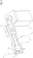
Figur 1 zeigt eine perspektivische Ansicht einer erfindungsgemäßen Trennvorrichtung. -
Figur 2 zeigt eine weitere perspektivische Ansicht der inFig. 1 dargestellten Trennvorrichtung. -
Figur 3 zeigt eine Draufsicht auf die in denFig. 1 und2 dargestellte Trennvorrichtung, bei der sich das Trennmesser in der Bereitschaftsposition befindet. -
Figur 4 zeigt eine Detailansicht der inFig. 3 dargestellten Draufsicht kurz vor dem Erreichen der Trennposition. -
Figur 5 zeigt eine Detailansicht der inFig. 3 dargestellten Draufsicht beim Erreichen der Trennposition. -
Figur 6 zeigt eine alternative Detailansicht der inFig. 5 dargestellten Draufsicht beim Erreichen der Trennposition. - Die in den
Fig. 1 bis 3 dargestellte Trennvorrichtung 1 verfügt über einen Antrieb 2, der mit dem Trennmesser 10 gekoppelt ist. Wie hier gezeigt, kann diese Kopplung bevorzugt über eine Pleuelstange 14 erfolgen, die das in einer Messerführung 13 geführte Trennmesser 10 mit einem auf der um die Achse der drehenden Antriebswelle des Antriebs 2 angeordneten Exzenter 16 koppelt. Die Pleuelstange 14 ist mit dem Exzenter 16 an der Gelenkachse A und mit dem Trennmesser 10 an der Gelenkachse B angelenkt. Über diesen Pleuelantrieb kann also bei Umdrehung des Antriebs das Trennmesser 10 aus der in denFig. 1 bis 3 dargestellten Bereitschaftsposition, bei der das Beschichtungsmaterial K, z. B. ein Kantenband, in dem Spalt 15 zwischen dem Trennmesser 10 und einem Gegenmesser bzw. Gegenlager 11 mit Spiel geführt wird, in oder entgegen der Vorschubrichtung X geführt werden. Z bezeichnet die Vertikalrichtung senkrecht zur Vorschubrichtung. X, Y bezeichnet eine Querrichtung, dabei kann es sich beispielsweise um die Förder- oder Zuführrichtung des Beschichtungsmaterials K handeln. Die Förderung des Beschichtungsmaterials K geschieht durch eine hier nicht gezeigte Zuführeinrichtung, in deren Bereich die Trennvorrichtung 1 innerhalb einer Kantenbearbeitungsvorrichtung angeordnet ist. - Am Trennmesser ist im Bereich seiner Schneide 10a (
Fig. 3 ) erfindungsgemäß ein Klemmelement 12 angeordnet bzw. angebracht. Das Klemmelement 12 ist entweder elastisch verformbar ausgebildet oder relativ zum Trennmesser 10 beweglich gelagert. Falls das Klemmelement 12 selbst angetrieben ist, entweder durch den Antrieb 2 oder einen eigenen Antrieb, ist auch vorstellbar, dass das Klemmelement 12 nicht am Trennmesser 10, sondern an einem anderen Bauteil angebracht ist, beispielsweise an der Messerführung 13. Die gesamte Trennvorrichtung 1 kann um die Schwenkachse S geschwenkt werden, sodass sie mit der Bewegung des Beschichtungsmaterials mitgeführt werden kann. Dabei muss es sich nicht zwingend um eine Schwenkbewegung handeln, vorstellbar ist auch, dass die Trennvorrichtung 1 sich linear und synchron mit dem Beschichtungsmaterial K, beispielsweise in Richtung Y, mitbewegt. - In der Bereitschaftsposition, die in der
Fig. 3 dargestellt ist, durchläuft das Beschichtungsmaterial K den Spalt 15 zwischen dem Trennmesser 10 bzw. der Schneide 10a und dem Gegenlager 11 mit Spiel. Die in Vorschubrichtung X vorauslaufende vordere Kante 12a des Klemmelements 12 - also der dem Gegenlager 11 zugewandte Abschnitt des Klemmelements 12 - ragt in Vorschubrichtung über die Schneide 10a hinaus oder ist wenigstens bündig mit der Schneide 10a angeordnet. Wie oben erwähnt, muss das nicht unbedingt so sein. Bei einem selbst relativ zum Trennmesser 10 beweglichen Klemmelement 12 kann dieses beispielsweise erst kurz vor dem Schnitt in die über das Trennmesser 10 hinausragende oder die bündige Stellung vorgeschoben werden. Beim Beginn des Trennvorgangs wird das Trennmesser 10 in Vorschubrichtung X in Richtung auf das Beschichtungsmaterial K vorgeschoben, dabei kommt die der Schneide 10a vorauslaufende vordere Kante 12a mit dem Beschichtungsmaterial K zunächst in Kontakt und schiebt das Beschichtungsmaterial K gegen das Gegenlager 11. Dadurch entsteht eine Klemmwirkung zwischen dem Klemmelement 12, dem Beschichtungsmaterial K und dem Gegenlager 11. Diese Situation ist inFig. 4 dargestellt. Dabei kann das Trennmesser 10 linear oder/und schwenkend um die Schwenkachse S (vgl.Fig. 3 ) mit dem Beschichtungsmaterial K mitbewegt werden. - Bei weiterem Vorschub des Trennmessers 10 in Vorschubrichtung X in Richtung auf das Gegenlager 11 wird die vordere Kante 12a und damit das Klemmelement 12 infolge der ansteigenden Klemmkraft in Richtung des Pfeils P verdrängt, entweder durch Verschieben (
Fig. 5 ) des Klemmelements 12, wenn dieses auf irgendeine Weise verschieblich gelagert ist, oder durch elastische Verformung, sofern das Klemmelement 12 beispielsweise ein Gummimaterial, ein Kunststoffmaterial oder ein Elastomermaterial ist; diese Situation ist inFig. 6 durch die Wölbung W angedeutet. Wird das Trennmesser 10 weiter vorgeschoben, so erreicht es schließlich die durch die gestrichelte Linie 10a' angedeutete Trennposition. Hierbei springt dann das Klemmelement 12 hinter die Schneide 10a des Trennmessers 10 zurück, sodass die Schneide freigegeben wird und das Beschichtungsmaterial K durchtrennen kann. Ist die Trennung des Beschichtungsmaterials erfolgt, kehrt das Trennmesser 10 in die Bereitschaftsposition zurück. -
- 1
- Trennvorrichtung
- 2
- Antrieb
- 10
- Trennmesser
- 10a
- Schneide von 10
- 11
- Gegenlager
- 12
- Klemmelement
- 12a
- vordere Kante von 12
- 13
- Messerführung
- 14
- Pleuelstange
- 15
- Spalt
- 16
- Exzenter
- K
- Beschichtungsmaterial
- S -
- Schwenkachse von 1
- A -
- Gelenkachse von 14 an 16
- B -
- Gelenkachse von 14 an 13
- E -
- Drehachse von 16
- W -
- Wölbung von 12
Claims (15)
- Trennvorrichtung (1) zum Durchtrennen von Beschichtungsmaterialien (K), aufweisendein Trennmesser (10) mit einer Schneide (10a) sowie einen mit dem Trennmesser (10) gekoppelten Antrieb (2), der so ausgebildet ist, dass er das Trennmesser (10), aus einer Bereitschaftsposition in eine Trennposition verlagern kann,wobei die Trennvorrichtung (1) weiter ein Gegenlager (11) aufweist, welches dazu dient, ein Beschichtungsmaterial (K) beim Durchtrennen desselben zu unterstützen,dadurch gekennzeichnet,dass am Trennmesser (10) ein Klemmelement (12) angeordnet ist, welches so ausgebildet ist, dass es sichi) in der Trennposition soweit elastisch verformen und/oderii) als am Trennmesser verschiebliches, bevorzugt durch eine Feder in Richtung auf das Gegenlager (11) vorgespanntes Element relativ zum Trennmesser (10) verschieben lässt,dass das Klemmelement (12) gegenüber dem Trennmesser (10) hinter die Schneide (10a) des Trennmessers (10) zurückspringt.
- Trennvorrichtung (1) nach Anspruch 1,
dadurch gekennzeichnet,
dass es sich bei dem Klemmelement (12) um ein Bauteil aus einem elastischen Material, insbesondere einem Kunststoff oder einem Gummimaterial oder einem Elastomermaterial, handelt. - Trennvorrichtung (1) nach Anspruch 1,
dadurch gekennzeichnet,
dass das Klemmelement (12) selbst aus einem federnden Material, insbesondere Federstahlausgebildet ist. - Trennvorrichtung (1) nach einem der vorigen Ansprüche,
dadurch gekennzeichnet,
dass das Klemmelement (12) über den oder einen separaten Antrieb relativ zum Trennmesser beweglich, insbesondere verschieblich, angetrieben ist. - Trennvorrichtung (1) nach einem der vorigen Ansprüche,
dadurch gekennzeichnet,
dass der Antrieb (2) ein linear wirkender Antrieb oder/und ein pneumatischer Antrieb ist oder über einen Exzenter, insbesondere über eine Pleuelstange (14), mit dem Trennmesser (10) gekoppelt ist. - Trennvorrichtung (1) nach einem der vorigen Ansprüche,
dadurch gekennzeichnet,
dass das Klemmelement (12) im unbelasteten Zustand in Richtung des Gegenlagers (11) bündig zu der Schneide (10a) des Trennmessers (10) angeordnet ist oder über diese hinausragt. - Kantenbearbeitungsvorrichtung zur Beschichtung der Schmalseiten von plattenförmigen Werkstücken aus Holz oder Holzersatzstoffen mit Beschichtungsmaterialien (K), wobei die Kantenbearbeitungsvorrichtung eine Zuführeinrichtung aufweist, die ein Beschichtungsmaterial (K) an ein Werkstück heranführt, wobei im Bereich der Zuführeinrichtung eine Trennvorrichtung (1) zum Durchtrennen von Beschichtungsmaterialien (K)angeordnet, welche ein Trennmesser (10) mit einer Schneide (10a) sowie einen mit dem Trennmesser (10) gekoppelten Antrieb (2) aufweist, der so ausgebildet ist, dass er das Trennmesser (10), aus einer Bereitschaftsposition in eine Trennposition verlagern kann,wobei die Trennvorrichtung (1) weiter ein Gegenlager (11) aufweist, welches dazu dient, ein Beschichtungsmaterial (K) beim Durchtrennen desselben zu unterstützen,dadurch gekennzeichnet,dass am Trennmesser (10) ein Klemmelement (12) angeordnet ist, welches so ausgebildet ist, dass es sich in der Trennposition soweit elastisch verformen und/oder relativ zum Trennmesser (10) verschieben lässt, dass es gegenüber dem Trennmesser (10) hinter die Schneide (10a) des Trennmessers (10) zurückspringt.
- Kantenbearbeitungsvorrichtung nach Anspruch 7,
dadurch gekennzeichnet,
dass die Trennvorrichtung (1) rotatorisch und/oder translatorisch gelagert ist, so dass sie mit dem Beschichtungsmaterial (K) mitbewegt werden kann. - Kantenbearbeitungsvorrichtung nach Anspruch 7 oder 8,
dadurch gekennzeichnet,
dass es sich bei dem Klemmelement (12) um ein Bauteil aus einem elastischen Material, insbesondere einem Kunststoff oder einem Gummimaterial oder einem Elastomermaterial, handelt. - Kantenbearbeitungsvorrichtung nach Anspruch 7 oder 8,
dadurch gekennzeichnet,
dass das Klemmelement (12) selbst aus einem federnden Material, insbesondere Federstahl und/oder als am Trennmesser verschiebliches Element ausgebildet ist, welches bevorzugt durch eine Feder in Richtung auf das Gegenlager (11) vorgespannt ist. - Kantenbearbeitungsvorrichtung nach einem der Ansprüche 7 bis 10,
dadurch gekennzeichnet,
dass das Klemmelement (12) über den oder einen separaten Antrieb relativ zum Trennmesser beweglich, insbesondere verschieblich, angetrieben ist. - Kantenbearbeitungsvorrichtung nach einem der Ansprüche 7 bis 11,
dadurch gekennzeichnet,
dass der Antrieb (2) ein linear wirkender Antrieb oder/und ein pneumatischer Antrieb ist oder über einen Exzenter, insbesondere über eine Pleuelstange (14), mit dem Trennmesser (10) gekoppelt ist. - Kantenbearbeitungsvorrichtung nach einem der Ansprüche 7 bis 12,
dadurch gekennzeichnet,
dass das Klemmelement (12) im unbelasteten Zustand in Richtung des Gegenlagers (11) bündig zu der Schneide (10a) des Trennmessers (10) angeordnet ist oder über diese hinausragt. - Verfahren zum Durchtrennen eines Beschichtungsmaterials (K), welches einem Werkstück in einer Kantenbearbeitungsvorrichtung nach einem der Ansprüche 7 bis 13 zugeführt wird, bei welchem das Trennmesser (10) zum Durchtrennen des Beschichtungsmaterials (K) aus einer Bereitschaftsposition, in welcher das zugeführte Beschichtungsmaterial (K) in einem Spalt (15) zwischen dem Gegenlager (11) und der Schneide (12) des Trennmessers (10) hindurchgeführt wird, in eine Trennposition bewegt wird, wobei beim Bewegen in die Trennposition das Beschichtungsmaterial (K) durch das Klemmelement (12) gegen das Gegenlager (11) in die Klemmposition geschoben und zwischen Klemmelement (12) und Gegenlager (11) eingeklemmt wird, und wobei anschließend das eingeklemmte Beschichtungsmaterial (K) von der Schneide (10a) unter fortgesetztem Bewegen des Trennmessers (10) in Richtung des Gegenlagers (11) unter gleichzeitiger elastischer Verformung oder Verschiebung des Klemmelements (12) durchtrennt wird.
- Verfahren nach Anspruch 14,
dadurch gekennzeichnet,
dass die Trennvorrichtung (1) mit dem Kantenband (K) mitbewegt, insbesondere linear verschoben oder geschwenkt wird.
Applications Claiming Priority (1)
| Application Number | Priority Date | Filing Date | Title |
|---|---|---|---|
| DE102021124866.3A DE102021124866B3 (de) | 2021-09-27 | 2021-09-27 | Trennvorrichtung, Kantenbearbeitungsvorrichtung und Verfahren zum Durchtrennen eines Beschichtungsmaterials |
Publications (2)
| Publication Number | Publication Date |
|---|---|
| EP4155039A1 EP4155039A1 (de) | 2023-03-29 |
| EP4155039B1 true EP4155039B1 (de) | 2025-06-11 |
Family
ID=83398309
Family Applications (1)
| Application Number | Title | Priority Date | Filing Date |
|---|---|---|---|
| EP22193489.6A Active EP4155039B1 (de) | 2021-09-27 | 2022-09-01 | Trennvorrichtung, kantenbearbeitungsvorrichtung und verfahren zum durchtrennen eines beschichtungsmaterials |
Country Status (3)
| Country | Link |
|---|---|
| EP (1) | EP4155039B1 (de) |
| DE (1) | DE102021124866B3 (de) |
| PL (1) | PL4155039T3 (de) |
Citations (1)
| Publication number | Priority date | Publication date | Assignee | Title |
|---|---|---|---|---|
| GB742033A (en) * | 1952-07-31 | 1955-12-21 | Carl Heinz Muller | Improvements in and relating to motor driven shears for veneer strips and the like |
Family Cites Families (10)
| Publication number | Priority date | Publication date | Assignee | Title |
|---|---|---|---|---|
| SE447218B (sv) * | 1985-06-13 | 1986-11-03 | Delkani Sa | Sett att formatskera en stapel av arkmaterial |
| DE4344997A1 (de) | 1993-12-30 | 1995-07-06 | Stefan Borowetzke | Rahmenhalterung für Kantenbearbeitungswerkzeuge |
| DE19917741A1 (de) | 1999-04-20 | 2000-10-26 | Ima Maschinenfabriken Klessmann Gmbh | Vorrichtung zum Anfahren eines Kantenstreifens an eine Schmalflächenseite einer eckigen Platte |
| DE10305022A1 (de) | 2003-02-07 | 2004-08-19 | Schulte-Göbel, Christof | Kantenanleimvorrichtung |
| DE202008015878U1 (de) * | 2008-12-01 | 2010-04-15 | Homag Holzbearbeitungssysteme Ag | Vorrichtung zum Beschichten von Werkstücken |
| DE102011114763A1 (de) * | 2011-10-01 | 2013-04-04 | Ima Klessmann Gmbh Holzbearbeitungssysteme | Verfahren und Vorrichtung zur Anbringung eines Kantenbandabschnitts |
| CN109070380B (zh) | 2016-01-15 | 2021-10-29 | 希菲斯有限公司 | 封边设备和方法 |
| DE102016118866B4 (de) | 2016-10-05 | 2022-06-23 | Holger Kluge | Mobile Kantenstreifenaufbringvorrichtung |
| DE102019112600A1 (de) | 2019-05-14 | 2020-11-19 | Felder Kg | Vorrichtung zur Beschichtung einer Oberfläche |
| DE102019135438A1 (de) | 2019-12-20 | 2021-07-08 | Homag Gmbh | Kappeinrichtung, Beschichtungseinrichtung sowie Verfahren zum Ablängen eines Schmalflächenbeschichtungsmaterials |
-
2021
- 2021-09-27 DE DE102021124866.3A patent/DE102021124866B3/de active Active
-
2022
- 2022-09-01 EP EP22193489.6A patent/EP4155039B1/de active Active
- 2022-09-01 PL PL22193489.6T patent/PL4155039T3/pl unknown
Patent Citations (1)
| Publication number | Priority date | Publication date | Assignee | Title |
|---|---|---|---|---|
| GB742033A (en) * | 1952-07-31 | 1955-12-21 | Carl Heinz Muller | Improvements in and relating to motor driven shears for veneer strips and the like |
Also Published As
| Publication number | Publication date |
|---|---|
| PL4155039T3 (pl) | 2025-10-20 |
| DE102021124866B3 (de) | 2022-10-20 |
| EP4155039A1 (de) | 2023-03-29 |
Similar Documents
| Publication | Publication Date | Title |
|---|---|---|
| DE69017819T2 (de) | Druckklebstoffschliesssystem. | |
| DE4101399A1 (de) | Vorrichtung zum falten von blaettern | |
| DE69315337T2 (de) | Maschine zum schneiden von bogen aus einer papierbahn und zum gleichzeitigen schneiden eines querstreifens | |
| EP0438736B1 (de) | Vorrichtung zum Schneiden von gestapeltem, blattförmigem Gut mit einem Frontaufstosser zum Ausrichten des Gutes an einer Vorschubeinheit | |
| DD298365A5 (de) | Heftapparat | |
| EP0049016A1 (de) | Transportvorrichtung für Papierbahnen in Buchungsmaschinen | |
| EP2517892B1 (de) | Vorrichtung und Verfahren zur Herstellung von gebundenen, einen Fälzelstreifen oder einen Umschlag aufweisenden Buchblocks | |
| EP4155039B1 (de) | Trennvorrichtung, kantenbearbeitungsvorrichtung und verfahren zum durchtrennen eines beschichtungsmaterials | |
| DE68912280T2 (de) | Klebestreifen-Anbringeinheit für Pappschachtelklebestreifen-Anbringmaschinen mit einer verbesserten Rückstellbewegung der Eingangsandruckrolle. | |
| DE10223894B4 (de) | Plattenklemmvorrichtung | |
| DE4227930A1 (de) | Vorrichtung zum Schneiden und Heften von mehrlagigen Druckprodukten in Falzapparaten | |
| EP4015172B1 (de) | Vorrichtung und verfahren zum andrücken von kantenbändern | |
| EP1990152A1 (de) | Kantenanleimaggregat und Verfahren zum Anleimen von Kantenmaterial | |
| EP1329334B1 (de) | Beleimstation von Klebebinden von Blattblöcken | |
| WO2018015162A1 (de) | Furnierschichtholzprodukt und verfahren zu seiner herstellung | |
| DE102005009328B4 (de) | Vorrichtung und Verfahren zum maschinellen Falzen eines im wesentlichen ebenen Materialbogens | |
| EP2133274B1 (de) | Verpackungsmaschine mit einer Andrückrollvorrichtung | |
| EP4257309B1 (de) | Messerhalter für schneidmaschinen | |
| DE202022003268U1 (de) | Press- und Trennvorrichtung sowie System zum Umwandeln eines bahnförmigen Ausgangsmaterials in Verpackungstaschen | |
| DE3003555A1 (de) | Vorrichtung zum zufuehren von streifenmaterial an einer kantenanleimmaschine | |
| DE102022113465A1 (de) | Press- und trennvorrichtung sowie system zum umwandeln eines bahnförmigen ausgangsmaterials in verpackungstaschen | |
| DE102004005334B4 (de) | Vorrichtung zum Kaschieren zylindrischer Teile | |
| DE2917608A1 (de) | Vorrichtung zum maschinellen einschlagen von buechern in schutzumschlaege | |
| DE10058437A1 (de) | Vorrichtungen zum Verbinden zweier Bahnen | |
| DE7321921U (de) | Magazin fuer furnierstreifen oder leisten |
Legal Events
| Date | Code | Title | Description |
|---|---|---|---|
| PUAI | Public reference made under article 153(3) epc to a published international application that has entered the european phase |
Free format text: ORIGINAL CODE: 0009012 |
|
| STAA | Information on the status of an ep patent application or granted ep patent |
Free format text: STATUS: THE APPLICATION HAS BEEN PUBLISHED |
|
| AK | Designated contracting states |
Kind code of ref document: A1 Designated state(s): AL AT BE BG CH CY CZ DE DK EE ES FI FR GB GR HR HU IE IS IT LI LT LU LV MC MK MT NL NO PL PT RO RS SE SI SK SM TR |
|
| STAA | Information on the status of an ep patent application or granted ep patent |
Free format text: STATUS: REQUEST FOR EXAMINATION WAS MADE |
|
| 17P | Request for examination filed |
Effective date: 20230927 |
|
| RBV | Designated contracting states (corrected) |
Designated state(s): AL AT BE BG CH CY CZ DE DK EE ES FI FR GB GR HR HU IE IS IT LI LT LU LV MC MK MT NL NO PL PT RO RS SE SI SK SM TR |
|
| GRAP | Despatch of communication of intention to grant a patent |
Free format text: ORIGINAL CODE: EPIDOSNIGR1 |
|
| STAA | Information on the status of an ep patent application or granted ep patent |
Free format text: STATUS: GRANT OF PATENT IS INTENDED |
|
| INTG | Intention to grant announced |
Effective date: 20250129 |
|
| GRAS | Grant fee paid |
Free format text: ORIGINAL CODE: EPIDOSNIGR3 |
|
| GRAA | (expected) grant |
Free format text: ORIGINAL CODE: 0009210 |
|
| STAA | Information on the status of an ep patent application or granted ep patent |
Free format text: STATUS: THE PATENT HAS BEEN GRANTED |
|
| AK | Designated contracting states |
Kind code of ref document: B1 Designated state(s): AL AT BE BG CH CY CZ DE DK EE ES FI FR GB GR HR HU IE IS IT LI LT LU LV MC MK MT NL NO PL PT RO RS SE SI SK SM TR |
|
| REG | Reference to a national code |
Ref country code: GB Ref legal event code: FG4D Free format text: NOT ENGLISH |
|
| REG | Reference to a national code |
Ref country code: CH Ref legal event code: EP |
|
| REG | Reference to a national code |
Ref country code: DE Ref legal event code: R096 Ref document number: 502022004222 Country of ref document: DE |
|
| REG | Reference to a national code |
Ref country code: IE Ref legal event code: FG4D Free format text: LANGUAGE OF EP DOCUMENT: GERMAN |
|
| PG25 | Lapsed in a contracting state [announced via postgrant information from national office to epo] |
Ref country code: ES Free format text: LAPSE BECAUSE OF FAILURE TO SUBMIT A TRANSLATION OF THE DESCRIPTION OR TO PAY THE FEE WITHIN THE PRESCRIBED TIME-LIMIT Effective date: 20250611 Ref country code: FI Free format text: LAPSE BECAUSE OF FAILURE TO SUBMIT A TRANSLATION OF THE DESCRIPTION OR TO PAY THE FEE WITHIN THE PRESCRIBED TIME-LIMIT Effective date: 20250611 |
|
| REG | Reference to a national code |
Ref country code: LT Ref legal event code: MG9D |
|
| PG25 | Lapsed in a contracting state [announced via postgrant information from national office to epo] |
Ref country code: GR Free format text: LAPSE BECAUSE OF FAILURE TO SUBMIT A TRANSLATION OF THE DESCRIPTION OR TO PAY THE FEE WITHIN THE PRESCRIBED TIME-LIMIT Effective date: 20250912 Ref country code: NO Free format text: LAPSE BECAUSE OF FAILURE TO SUBMIT A TRANSLATION OF THE DESCRIPTION OR TO PAY THE FEE WITHIN THE PRESCRIBED TIME-LIMIT Effective date: 20250911 |
|
| REG | Reference to a national code |
Ref country code: NL Ref legal event code: MP Effective date: 20250611 |
|
| PG25 | Lapsed in a contracting state [announced via postgrant information from national office to epo] |
Ref country code: BG Free format text: LAPSE BECAUSE OF FAILURE TO SUBMIT A TRANSLATION OF THE DESCRIPTION OR TO PAY THE FEE WITHIN THE PRESCRIBED TIME-LIMIT Effective date: 20250611 |
|
| PG25 | Lapsed in a contracting state [announced via postgrant information from national office to epo] |
Ref country code: HR Free format text: LAPSE BECAUSE OF FAILURE TO SUBMIT A TRANSLATION OF THE DESCRIPTION OR TO PAY THE FEE WITHIN THE PRESCRIBED TIME-LIMIT Effective date: 20250611 |
|
| PGFP | Annual fee paid to national office [announced via postgrant information from national office to epo] |
Ref country code: AT Payment date: 20251020 Year of fee payment: 4 |
|
| PG25 | Lapsed in a contracting state [announced via postgrant information from national office to epo] |
Ref country code: RS Free format text: LAPSE BECAUSE OF FAILURE TO SUBMIT A TRANSLATION OF THE DESCRIPTION OR TO PAY THE FEE WITHIN THE PRESCRIBED TIME-LIMIT Effective date: 20250911 |
|
| PG25 | Lapsed in a contracting state [announced via postgrant information from national office to epo] |
Ref country code: LV Free format text: LAPSE BECAUSE OF FAILURE TO SUBMIT A TRANSLATION OF THE DESCRIPTION OR TO PAY THE FEE WITHIN THE PRESCRIBED TIME-LIMIT Effective date: 20250611 |
|
| PG25 | Lapsed in a contracting state [announced via postgrant information from national office to epo] |
Ref country code: NL Free format text: LAPSE BECAUSE OF FAILURE TO SUBMIT A TRANSLATION OF THE DESCRIPTION OR TO PAY THE FEE WITHIN THE PRESCRIBED TIME-LIMIT Effective date: 20250611 |
|
| PG25 | Lapsed in a contracting state [announced via postgrant information from national office to epo] |
Ref country code: PT Free format text: LAPSE BECAUSE OF FAILURE TO SUBMIT A TRANSLATION OF THE DESCRIPTION OR TO PAY THE FEE WITHIN THE PRESCRIBED TIME-LIMIT Effective date: 20251013 |
|
| PG25 | Lapsed in a contracting state [announced via postgrant information from national office to epo] |
Ref country code: IS Free format text: LAPSE BECAUSE OF FAILURE TO SUBMIT A TRANSLATION OF THE DESCRIPTION OR TO PAY THE FEE WITHIN THE PRESCRIBED TIME-LIMIT Effective date: 20251011 |
|
| PGFP | Annual fee paid to national office [announced via postgrant information from national office to epo] |
Ref country code: DE Payment date: 20251110 Year of fee payment: 4 |
|
| PG25 | Lapsed in a contracting state [announced via postgrant information from national office to epo] |
Ref country code: SM Free format text: LAPSE BECAUSE OF FAILURE TO SUBMIT A TRANSLATION OF THE DESCRIPTION OR TO PAY THE FEE WITHIN THE PRESCRIBED TIME-LIMIT Effective date: 20250611 |
|
| PGFP | Annual fee paid to national office [announced via postgrant information from national office to epo] |
Ref country code: IT Payment date: 20250930 Year of fee payment: 4 |
|
| PG25 | Lapsed in a contracting state [announced via postgrant information from national office to epo] |
Ref country code: CZ Free format text: LAPSE BECAUSE OF FAILURE TO SUBMIT A TRANSLATION OF THE DESCRIPTION OR TO PAY THE FEE WITHIN THE PRESCRIBED TIME-LIMIT Effective date: 20250611 |
|
| PGFP | Annual fee paid to national office [announced via postgrant information from national office to epo] |
Ref country code: PL Payment date: 20250821 Year of fee payment: 4 |
|
| PG25 | Lapsed in a contracting state [announced via postgrant information from national office to epo] |
Ref country code: EE Free format text: LAPSE BECAUSE OF FAILURE TO SUBMIT A TRANSLATION OF THE DESCRIPTION OR TO PAY THE FEE WITHIN THE PRESCRIBED TIME-LIMIT Effective date: 20250611 |
|
| PG25 | Lapsed in a contracting state [announced via postgrant information from national office to epo] |
Ref country code: SK Free format text: LAPSE BECAUSE OF FAILURE TO SUBMIT A TRANSLATION OF THE DESCRIPTION OR TO PAY THE FEE WITHIN THE PRESCRIBED TIME-LIMIT Effective date: 20250611 |
|
| PG25 | Lapsed in a contracting state [announced via postgrant information from national office to epo] |
Ref country code: RO Free format text: LAPSE BECAUSE OF FAILURE TO SUBMIT A TRANSLATION OF THE DESCRIPTION OR TO PAY THE FEE WITHIN THE PRESCRIBED TIME-LIMIT Effective date: 20250611 |
|
| REG | Reference to a national code |
Ref country code: DE Ref legal event code: R097 Ref document number: 502022004222 Country of ref document: DE |
|
| PG25 | Lapsed in a contracting state [announced via postgrant information from national office to epo] |
Ref country code: DK Free format text: LAPSE BECAUSE OF FAILURE TO SUBMIT A TRANSLATION OF THE DESCRIPTION OR TO PAY THE FEE WITHIN THE PRESCRIBED TIME-LIMIT Effective date: 20250611 |
|
| PLBE | No opposition filed within time limit |
Free format text: ORIGINAL CODE: 0009261 |
|
| STAA | Information on the status of an ep patent application or granted ep patent |
Free format text: STATUS: NO OPPOSITION FILED WITHIN TIME LIMIT |
|
| REG | Reference to a national code |
Ref country code: CH Ref legal event code: L10 Free format text: ST27 STATUS EVENT CODE: U-0-0-L10-L00 (AS PROVIDED BY THE NATIONAL OFFICE) Effective date: 20260423 |