EP4154786B1 - Reinigungsvorrichtung mit staubsauger und andockstation - Google Patents
Reinigungsvorrichtung mit staubsauger und andockstation Download PDFInfo
- Publication number
- EP4154786B1 EP4154786B1 EP21831600.8A EP21831600A EP4154786B1 EP 4154786 B1 EP4154786 B1 EP 4154786B1 EP 21831600 A EP21831600 A EP 21831600A EP 4154786 B1 EP4154786 B1 EP 4154786B1
- Authority
- EP
- European Patent Office
- Prior art keywords
- dust collecting
- collecting chamber
- docking
- docking station
- cleaning apparatus
- Prior art date
- Legal status (The legal status is an assumption and is not a legal conclusion. Google has not performed a legal analysis and makes no representation as to the accuracy of the status listed.)
- Active
Links
Images


Classifications
-
- A—HUMAN NECESSITIES
- A47—FURNITURE; DOMESTIC ARTICLES OR APPLIANCES; COFFEE MILLS; SPICE MILLS; SUCTION CLEANERS IN GENERAL
- A47L—DOMESTIC WASHING OR CLEANING; SUCTION CLEANERS IN GENERAL
- A47L5/00—Structural features of suction cleaners
- A47L5/12—Structural features of suction cleaners with power-driven air-pumps or air-compressors, e.g. driven by motor vehicle engine vacuum
- A47L5/22—Structural features of suction cleaners with power-driven air-pumps or air-compressors, e.g. driven by motor vehicle engine vacuum with rotary fans
- A47L5/24—Hand-supported suction cleaners
- A47L5/26—Hand-supported suction cleaners with driven dust-loosening tools
-
- A—HUMAN NECESSITIES
- A47—FURNITURE; DOMESTIC ARTICLES OR APPLIANCES; COFFEE MILLS; SPICE MILLS; SUCTION CLEANERS IN GENERAL
- A47L—DOMESTIC WASHING OR CLEANING; SUCTION CLEANERS IN GENERAL
- A47L7/00—Suction cleaners adapted for additional purposes; Tables with suction openings for cleaning purposes; Containers for cleaning articles by suction; Suction cleaners adapted to cleaning of brushes; Suction cleaners adapted to taking-up liquids
- A47L7/0095—Suction cleaners or attachments adapted to collect dust or waste from power tools
-
- A—HUMAN NECESSITIES
- A47—FURNITURE; DOMESTIC ARTICLES OR APPLIANCES; COFFEE MILLS; SPICE MILLS; SUCTION CLEANERS IN GENERAL
- A47L—DOMESTIC WASHING OR CLEANING; SUCTION CLEANERS IN GENERAL
- A47L9/00—Details or accessories of suction cleaners, e.g. mechanical means for controlling the suction or for effecting pulsating action; Storing devices specially adapted to suction cleaners or parts thereof; Carrying-vehicles specially adapted for suction cleaners
- A47L9/10—Filters; Dust separators; Dust removal; Automatic exchange of filters
- A47L9/106—Dust removal
-
- A—HUMAN NECESSITIES
- A47—FURNITURE; DOMESTIC ARTICLES OR APPLIANCES; COFFEE MILLS; SPICE MILLS; SUCTION CLEANERS IN GENERAL
- A47L—DOMESTIC WASHING OR CLEANING; SUCTION CLEANERS IN GENERAL
- A47L9/00—Details or accessories of suction cleaners, e.g. mechanical means for controlling the suction or for effecting pulsating action; Storing devices specially adapted to suction cleaners or parts thereof; Carrying-vehicles specially adapted for suction cleaners
- A47L9/10—Filters; Dust separators; Dust removal; Automatic exchange of filters
- A47L9/14—Bags or the like; Rigid filtering receptacles; Attachment of, or closures for, bags or receptacles
- A47L9/1418—Impermeable dust collecting bags
-
- A—HUMAN NECESSITIES
- A47—FURNITURE; DOMESTIC ARTICLES OR APPLIANCES; COFFEE MILLS; SPICE MILLS; SUCTION CLEANERS IN GENERAL
- A47L—DOMESTIC WASHING OR CLEANING; SUCTION CLEANERS IN GENERAL
- A47L9/00—Details or accessories of suction cleaners, e.g. mechanical means for controlling the suction or for effecting pulsating action; Storing devices specially adapted to suction cleaners or parts thereof; Carrying-vehicles specially adapted for suction cleaners
- A47L9/10—Filters; Dust separators; Dust removal; Automatic exchange of filters
- A47L9/14—Bags or the like; Rigid filtering receptacles; Attachment of, or closures for, bags or receptacles
- A47L9/1427—Means for mounting or attaching bags or filtering receptacles in suction cleaners; Adapters
- A47L9/1436—Connecting plates, e.g. collars, end closures
- A47L9/1445—Connecting plates, e.g. collars, end closures with closure means
- A47L9/1454—Self-sealing closures, e.g. valves
-
- A—HUMAN NECESSITIES
- A47—FURNITURE; DOMESTIC ARTICLES OR APPLIANCES; COFFEE MILLS; SPICE MILLS; SUCTION CLEANERS IN GENERAL
- A47L—DOMESTIC WASHING OR CLEANING; SUCTION CLEANERS IN GENERAL
- A47L9/00—Details or accessories of suction cleaners, e.g. mechanical means for controlling the suction or for effecting pulsating action; Storing devices specially adapted to suction cleaners or parts thereof; Carrying-vehicles specially adapted for suction cleaners
- A47L9/10—Filters; Dust separators; Dust removal; Automatic exchange of filters
- A47L9/16—Arrangement or disposition of cyclones or other devices with centrifugal action
- A47L9/1683—Dust collecting chambers; Dust collecting receptacles
-
- A—HUMAN NECESSITIES
- A47—FURNITURE; DOMESTIC ARTICLES OR APPLIANCES; COFFEE MILLS; SPICE MILLS; SUCTION CLEANERS IN GENERAL
- A47L—DOMESTIC WASHING OR CLEANING; SUCTION CLEANERS IN GENERAL
- A47L9/00—Details or accessories of suction cleaners, e.g. mechanical means for controlling the suction or for effecting pulsating action; Storing devices specially adapted to suction cleaners or parts thereof; Carrying-vehicles specially adapted for suction cleaners
- A47L9/10—Filters; Dust separators; Dust removal; Automatic exchange of filters
- A47L9/16—Arrangement or disposition of cyclones or other devices with centrifugal action
- A47L9/1691—Mounting or coupling means for cyclonic chamber or dust receptacles
-
- A—HUMAN NECESSITIES
- A47—FURNITURE; DOMESTIC ARTICLES OR APPLIANCES; COFFEE MILLS; SPICE MILLS; SUCTION CLEANERS IN GENERAL
- A47L—DOMESTIC WASHING OR CLEANING; SUCTION CLEANERS IN GENERAL
- A47L9/00—Details or accessories of suction cleaners, e.g. mechanical means for controlling the suction or for effecting pulsating action; Storing devices specially adapted to suction cleaners or parts thereof; Carrying-vehicles specially adapted for suction cleaners
- A47L9/28—Installation of the electric equipment, e.g. adaptation or attachment to the suction cleaner; Controlling suction cleaners by electric means
- A47L9/2868—Arrangements for power supply of vacuum cleaners or the accessories thereof
- A47L9/2873—Docking units or charging stations
Definitions
- the disclosure relates to a cleaning apparatus including a vacuum cleaner and a docking station, and more specifically, to a docking station and a cleaning apparatus capable of automatically discharging dust inside a vacuum cleaner.
- a vacuum cleaner is a device that is equipped with a fan motor generating suction power, and through the suction power generated by the fan motor, suctions foreign substances, such as dust, together with air, separates the foreign substances contained in the suctioned air from the air, and collects the dust to perform cleaning.
- the vacuum cleaner includes a dust collecting chamber for collecting foreign substances, and a user needs to periodically separate the foreign substances collected in the dust collecting chamber from the vacuum cleaner and discharge the separated foreign substances from the dust collecting chamber.
- WO 2015/129387 A1 discloses a vacuum cleaner comprising a vacuum cleaner body and a charging stand.
- DE 20 2018 103929 U1 discloses a vacuum cleaner and a charging stand.
- EP 3 524 115 A1 discloses a cleaner support mechanism and a cleaner unit.
- One aspect of the disclosure provides a cleaning apparatus including a docking station of a vacuum cleaner capable of automatically discharging foreign substances from a dust collecting chamber.
- a cleaning apparatus including a docking station capable of discharging foreign substances from a dust collecting chamber while charging a battery of a vacuum cleaner.
- a cleaning apparatus including: a vacuum cleaner including a battery configured to generate a suction force and a dust collecting chamber in which foreign substances suctioned by the suction force are collected; and a docking station connected to the vacuum cleaner and having a long axis extending in a first direction, wherein the docking station includes: a charging part provided to come in contact with the battery to charge the battery; a docking part connected to the dust collecting chamber to remove the foreign substances collected in the dust collecting chamber; and a suction device configured to suction the foreign substances and internal air in the dust collecting chamber docked onto the docking part, wherein the docking part includes a docking opening that is opened in a second direction different from the first direction such that at least a portion of the dust collecting chamber is inserted into the docking opening.
- the charging part may be disposed upward of the docking part in the first direction.
- the first direction may be provided in a direction corresponding to an upper side and lower side direction of the docking station, and the second direction may be provided in a direction substantially perpendicular to the first direction.
- the first direction may be provided in a direction corresponding to an upper side and lower side direction of the docking station, and the second direction may be provided in a direction inclined with respect to the first direction.
- the dust collecting chamber may include a body provided in a cylindrical shape formed around an extension axis extending in one direction, and may be provided to be inserted into the docking part in an extending direction of the extension axis of the dust collecting chamber.
- the vacuum cleaner may further include: a suction unit configured to suction foreign substances; and an extension pipe connecting the suction unit and the dust collecting chamber to each other and having a long axis extending in one direction, and the long axis of the extension pipe and the extension axis of the dust collecting chamber may be provided to be substantially perpendicular to each other.
- the vacuum cleaner may further include: a suction unit configured to suction foreign substances; and an extension pipe connecting the suction unit and the dust collecting chamber to each other and having a long axis extending in one direction, and while the dust collecting chamber is docked onto the docking part, the vacuum cleaner may be supported on the docking station such that the long axis of the extension pipe extends in a direction corresponding to the first direction.
- the dust collecting chamber may further include: a dust collecting chamber opening that is opened in a direction corresponding to the extending direction of the extension axis of the body and formed at one end of the body; and a dust collecting chamber door configured to open and close the dust collecting chamber opening, and while the dust collecting chamber is inserted into the docking opening, the dust collecting chamber door may be provided to be disposed inside the docking part.
- the dust collecting chamber may further include a fixing member provided to fix the dust collecting chamber door to the body, and when pressed by an external force, release the fixing of the dust collecting chamber door, and the docking part may be configured to press the fixing member in response to the dust collecting chamber being inserted into the docking opening.
- the docking part may include an opening guide configured to press the fixing member in response to the dust collecting chamber being inserted into the docking opening.
- the dust collecting chamber door may be provided to rotate about a rotation shaft disposed at one side of one end of the body, and the dust collecting chamber may be provided such that, when the dust collecting chamber is inserted into the docking opening, the rotation shaft may be disposed on an upper end of the dust collecting chamber in the first direction.
- the dust collecting chamber may further include an elastic member disposed in an extending direction of the rotating shaft for the dust collecting chamber door to be biased in a direction toward the body.
- the dust collecting chamber may further include a pair of magnetic members disposed on the body and the dust collecting chamber door, respectively.
- the dust collecting chamber door may be provided to be rotated about the rotation shaft by a suction air current formed in the suction device when the suction device is driven.
- a cleaning apparatus including: a vacuum cleaner including a battery for generating a suction force, a dust collecting chamber in which foreign substances suctioned by the suction force are collected; and a docking station connected to each of the battery and the dust collecting chamber, wherein the docking station includes: a body including a docking surface having a docking opening to which the dust collecting chamber is docked and having a long axis extending in a first direction; a charging part connected to the battery and formed on an upper side of the docking surface in the first direction; a docking part communicating with the docking opening and provided to allow at least a part of the dust collecting chamber to be inserted thereinto remove foreign substances collected in the dust collecting chamber; and a suction device configured to suction the foreign substances and internal air in the dust collecting chamber docked onto the docking part, wherein the dust collecting chamber is provided to be inserted into the docking opening in a second direction perpendicular to the first direction.
- the docking station may be provided such that the charging part and the suction device are simultaneously operated.
- a cleaning apparatus including: a vacuum cleaner including a suction unit configured to suction foreign substances, a dust collecting chamber configured to collect the foreign substances suctioned from the suction unit, and an extension pipe connecting the suction unit to the dust collector and having a long axis extending in one direction; and a docking station connected to the vacuum cleaner and having a long axis extending in a first direction, wherein the docking station includes: a body including a docking surface having a docking opening to which the dust collecting chamber is docked and having a long axis extending in a first direction; a docking part communicating with the docking opening and provided to allow the dust collecting chamber to be inserted in a second direction different from the first direction to remove foreign substances collected in the dust collecting chamber; and a suction device configured to suction the foreign substances and internal air in the dust collecting chamber docked onto the docking part, wherein the dust collecting chamber is provided in a cylindrical shape having a long axis extending in
- the second direction may correspond to a direction perpendicular to the first direction.
- the vacuum cleaner may further include a cleaner body having a motor for forming a suction air current, and the dust collecting chamber may be integrally formed with the cleaner body.
- the cleaning apparatus can allow the docking station of the vacuum cleaner to charge the battery of the vacuum cleaner while automatically removing foreign substances collected in the dust collecting chamber of the vacuum cleaner.
- the dust collecting chamber of the vacuum cleaner when the dust collecting chamber of the vacuum cleaner is inserted into the docking station in a direction substantially perpendicular to a upper side and lower side direction, foreign substances collected in the dust collecting can be effectively removed.
- first means “first,” “second,” etc.
- the elements are not limited by the terms, and the terms are only used to distinguish one element from another.
- a first element could be termed a second element, and similarly, a second element could be termed a first element without departing from the scope of the disclosure.
- the term "and/or” includes combinations of one or all of a plurality of associated listed items.
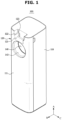
- FIG. 1 is a perspective view illustrating a docking station of a cleaning apparatus according to an embodiment of the disclosure
- FIG. 2 is a view illustrating a state in which a vacuum cleaner of a cleaning apparatus according to an embodiment of the disclosure is separated from a docking station
- FIG. 3 is a view illustrating a side cross-section of a part of a docking station in a state in which a vacuum cleaner of a cleaning apparatus according to an embodiment of the disclosure is docked onto a docking station
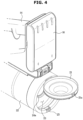
- FIG. 4 is a perspective view illustrating a part of a vacuum cleaner of a cleaning apparatus according to an embodiment of the disclosure.
- a cleaning apparatus 1 may include a cleaner 10 and a docking station 100.
- the cleaner 10 may include a cleaner body 11, an extension pipe 17 detachably coupled to the cleaner body 11, a suction unit 18 detachably coupled to the extension pipe 17, and a dust collecting chamber 20 connected to the cleaner body.
- the cleaner body 11 may include a suction motor (not shown) that generates a suction force required to suction foreign substances on a surface to be cleaned.
- the dust collecting chamber 20 may be disposed upstream of the suction motor (not shown) in an air current, to filter out dust or dirt in the air introduced through the main suction unit 18 and collect the filtered dust or dirt.
- the dust collecting chamber 20 may be integrally formed with the cleaner body 11.
- the cleaner body 11 and the dust collecting chamber 20 may provide a structure in which the dust collecting chamber 20 is not arbitrarily separated from the cleaner body 11 in use.
- the disclosure is not limited thereto, and the dust collecting chamber 20 may be provided to be detachable from the cleaner body 11.
- the cleaner body 11 may include a handle 14 to be gripped by a user for manipulation of the cleaner 10. The user may hold the handle 14 and move the cleaner 10 in the front-rear direction.
- the cleaner body 11 may include a dust collection guide 15 for guiding foreign substances into the dust collecting chamber 20 by connecting the dust collecting chamber 20 to the extension pipe 17 and the suction unit 18.
- the dust collection guide 15 may be coupled to the above-described extension pipe 17 while guiding the foreign substances to the dust collecting chamber 20 as described above.
- the dust collection guide 15 may be provided to be directly coupled to the suction unit 18 other than the extension pipe 17 or may be coupled to other components, such as an auxiliary suction unit.
- the extension pipe 17 may extend to have a long axis X extending in one direction.
- the user may have an increased convenience of cleaning by coupling various components to the dust collection guide 15 according to the cleaning situation.
- the dust collecting chamber 20 may be provided in a cylindrical shape having an extension axis Y extending in a direction substantially perpendicular to a direction in which the long axis X of the extension pipe 17 extends.
- the dust collection guide 15 may be coupled to the extension pipe 17 such that the long axis X of the extension pipe 17 faces in a direction substantially perpendicular to the extending direction of the extension axis Y of the dust collecting chamber 20.
- the dust collecting chamber 20 may include a cylindrical body 22 extending in the extending direction of the extension axis Y.
- the dust collecting chamber 20 may be provided to collect foreign substances through centrifugal rotation separation through the cylindrical body 22.
- the dust collecting chamber 20 may include a multi-cyclone to collect foreign substances by centrifugal rotation separation.
- the dust collecting chamber 20 may include a dust collecting chamber door 21 that is disposed at a side opposite to a portion connected to the dust collection guide 15 in the extending direction of the extension axis Y and configured to open and close the dust collecting chamber 20.
- the user may open the dust collecting chamber door 21 to discharge the foreign substances collected in the dust collecting chamber 20 from the dust collecting chamber 20.
- the dust collecting chamber door 21 may be provided to open and close a dust collecting chamber opening 23 that is formed at one end of the body 22 of the dust collecting chamber 20 and provided to be open in the extending direction of the extension axis Y.
- the dust collecting chamber opening 23 may be openable in a direction substantially perpendicular to a direction in which the long axis X of the extension pipe 17 extends.
- the handle 14 may be disposed at a side of the dust collecting chamber 20 opposite to a side in which the extension pipe 17 is disposed.
- the cleaner 10 may include a battery 16 provided to provide a driving force to the cleaner 10.
- the battery 16 may be detachably mounted to the cleaner body 11. Specifically, the battery 16 may be disposed adjacent to the handle 14.
- the battery 16 may be disposed at a side of the dust collecting chamber 20 opposite to a side in which the extension pipe 17 is disposed.
- the battery 16 may be electrically connected to a charging terminal 123 provided in the docking station 100 to be described below.
- the battery 16 may be charged by receiving power from the charging terminal 123 provided in the docking station 100.
- the docking station 100 may be configured for the cleaner 10 to be stored or mounted thereon.
- the cleaner 10 may be charged in the docking station 100.
- the docking station 100 may include a body housing 110 that forms the external appearance of the docking station 100.
- the body housing 110 may be provided to have a long axis extending in one direction.
- the long axis of the body housing 110 may preferably be provided to extend in the upper side and lower side direction.
- the docking station 100 may be provided in the shape of a box extending approximately in the upper side and lower side direction.
- the docking station 100 may include a charging part 120 onto which the handle 14 of the cleaner 10 is docked to supply the battery 16 with power.
- the charging part 120 may include a battery mounting part 121 on which the battery 16 is mounted, a battery guide 122 for guiding the mounting of the battery 16 and a charging terminal 123 for supplying power to the battery 16 in response to the battery 16 being mounted on the charging part 120.
- the battery 16 may be provided detachably from the cleaner body 11. Accordingly, the cleaner 10 may be provided to be coupled with one or more replaceable batteries 16.
- the battery 16 may be disposed to be exposed to the outside as in the embodiment of the disclosure, but may be disposed inside the cleaner body 11 of the cleaner 10 with being exposed to the outside.
- the charging part 120 may be provided to seat at least a portion of the cleaner body 11, in which the battery 16 is disposed, thereon to charge the battery 16.
- the cleaner 10 may approach the docking station 100 in a second direction B, which is a direction approximately perpendicular to the first direction A, which is the extending direction of the docking station 100, to be docked onto the docking station 100. This is to allow the battery 16 of the cleaner 10 to be docked onto the docking station 100 at the same time as the dust collecting chamber 20 of the cleaner 10 is docked onto the docking station 100.
- the conventional docking station is provided to, when the cleaner is docked onto the docking station, supply the battery with power as described above.
- the docking station 100 according to an embodiment of the disclosure is further implemented to, when the cleaner 10 is docked onto the docking station 100, allow dust collected inside the dust collecting chamber 20 to be automatically discharged, so that convenience of the consumer is increased.
- the docking station 100 may be implemented to, when the cleaner 10 is docked, directly dock with the dust collecting chamber 20 so that dust collected inside the dust collecting chamber 20 may be automatically removed.
- the docking station 100 is provided to automatically discharge the dust collected in the dust collecting chamber 20 while charging the battery 16 of the cleaner 10 when the cleaner 10 is docked on the docking station 100.
- the docking station 100 may be provided to, when the cleaner 10 is docked onto the docking station 100, selectively charge the cleaner 10 only or charge the cleaner 10 while discharging dust of the dust collecting chamber 20 according to a user's selection.
- the docking station 100 may include a suction device 130 to discharge the dust collected in the dust collecting chamber 20 from the dust collecting chamber 20.
- the docking station 100 may include a controller (not shown) for a user to input a signal for driving the suction device 130.
- the user may input a signal to the controller (not shown) so that the docking station 100 is controlled to charge the battery 16 of the cleaner 10 while discharging the foreign substances collected in the dust collecting chamber 20.
- the disclosure is not limited thereto, and the controller (not shown) of the docking station 100 may be provided to drive the suction device 130 upon receiving a detection value of a sensor for detecting docking of the cleaner 10, so that the suction device 130 is automatically driven in response to the cleaner 10 being docked even without a signal inputted by a user.
- the docking station 100 may include a docking part 140 provided for the dust collecting chamber 20 to be docked onto the docking station 100.
- the body housing 110 may be provided to have a long axis extending in the first direction A.
- the first direction A may be provided in a direction corresponding to the upper side and lower side direction.
- the docking station 100 may be provided in a box shape extending in the upper side and lower side direction.
- the docking part 140 may be disposed in an upper portion of the body housing 110.
- the docking part 140 may be disposed at a lower side of the charging part 120 in the extending direction of the body housing 110.
- the charging part 120 may be disposed on the upper end of the body housing 110 in the extending direction of the body housing 110, and the docking part 140 may be disposed at a lower side of the charging part 120.
- the cleaner 10 may be docked onto the docking station 100 such that a side of the cleaner 10 on which the battery 16 is disposed is arranged on the upper side in the first direction A and a side of the cleaner 10 on which the extension pipe 17 is disposed is arranged on the lower side in the first direction A.
- the suction device 130 may be disposed inside the body housing 110.
- the suction device 130 may be disposed at a lower portion of the body housing 110 in the extending direction of the body housing 110.
- the docking station 100 may include a collecting part 150 for collecting foreign substances discharged from the dust collecting chamber 20.
- the collecting part 150 may be disposed inside the body housing 110.
- the collecting part 150 may be disposed at an upper side of the suction device 130.
- the charging part 120, the docking part 140, the collecting part 150, and the suction device 130 may be sequentially disposed in the extending direction of the body housing 110.
- the docking station 100 may include a suction flow path 141 connecting the docking part 140 and the collecting part 150 to each other and allowing foreign substances discharged from the dust collecting chamber 20 to be suctioned through the docking part 140 to the collecting part 150.
- the suction flow path 141 may be provided to extend in the extending direction of the body housing 110 to connect the docking part 140 and the collecting part 150 to each other.
- the docking part 140 may include a seating space 142 communicating with the suction flow path 141 and in which the dust collecting chamber 20 is seated.
- the docking part 140 may include a docking opening 143 provided so that the dust collecting chamber 20 is docked onto the docking station 100 from the outside of the docking station 100.
- At least a portion of the dust collecting chamber 20 may be provided to be inserted into the docking opening 143.
- the dust collecting chamber 20 may be seated on the seating space 142 through the docking opening 143.
- the docking opening 143 may be opened in a direction substantially perpendicular to the extending direction of the long axis of the body housing 110. That is, the docking opening 143 may be opened in the second direction B perpendicular to the first direction A.
- the docking station 100 is provided in a box shape extending in the upper side and lower side direction. Accordingly, the docking opening 143 may be provided to be opened in the front-rear direction or the left-right direction of the docking station 100.
- the seating space 142 may have one end provided to communicate with the docking opening 143, and the other end provided to communicate with the suction flow path 141. Accordingly, the seating space 142 may be provided in a bent shape in which the seating space 142 formed to extend in the second direction B is alsoformed to extend in the first direction A.
- the body housing 110 may include a docking surface 111 provided at a side in which the docking opening 143 is disposed and the cleaner 10 is docked.
- the docking surface 111 may be provided to form one surface of the body housing 110.
- the docking surface 111 may be provided to face in the second direction B, which is the direction the docking opening 143 is opened.
- the docking surface 111 may be provided in various shapes as well as a flat surface or a curved surface.
- the docking surface 111 may extend in a planar shape having a long axis extending in one direction. Since the body housing 110 is provided in a box shape extending in the first direction A, which is the upper side and lower side direction, as described above, the long axis of the docking surface 111 may extend in a direction corresponding to the first direction A.
- the docking opening 143 and the charging part 120 may be formed on the docking surface 111.
- the disclosure is not limited thereto, and the charging part 120 may be disposed upward of the docking surface 111, in detail, above the docking surface 111 in the extending direction of the docking surface 111.
- the cleaner 10 may be docked onto the docking station 100 in a direction facing the docking surface 111 of the docking station 100.
- the cleaner 10 may be provided to be docked onto the docking station 100 in the second direction B.
- the cleaner 10 may be docked onto the docking station 100 in a direction perpendicular to a direction in which the long axis of the docking surface 111 extends in the docking station 100.
- the cleaner 10 may be provided to be docked onto the docking station 100 in the second direction B that is perpendicular to the first direction A.
- the first direction A which is the extending direction of the long axis of the body housing 110, and the extension axis Y of the dust collecting chamber 20 are provided to face in directions approximately perpendicular to each other.
- the extension axis Y of the dust collecting chamber 20 may be inserted into the docking opening 143 of the docking station 100 in a direction corresponding to the second direction B. Accordingly, in a state in which the cleaner 10 is docked onto the docking station 100, the long axis X of the extension pipe 17 of the cleaner 10 may be disposed in a direction corresponding to the first direction A. This is because the long axis X of the extension pipe 17 and the extension axis Y of the dust collecting chamber 20 are provided to be perpendicular to each other.
- the extension pipe 17 of the cleaner 10 may be disposed to face other directions than the first direction A, so that the cleaner 10 docked onto the docking station 100 without the extension pipe 17 being separated by the user may lower the aesthetic sense and degrade the spatial efficiency of the space around the docking station 100.
- the usability of the docking station 100 may decrease.
- the cleaning apparatus 1 may be provided to allow the vacuum cleaner 10 to be docked onto the docking station 100 and allow substances collected in the dust collecting chamber 20 to be automatically discharged in the docking station 100 in a state in which the extension pipe 17 or the suction unit 18 is coupled to the dust collection guide 15 of the cleaner 10.
- the cleaning apparatus 1 may be provided to, when the cleaner 10 is docked onto the docking station 100, arrange the direction in which the long axis X of the extension pipe 17 of the cleaner 10 faces to be in the first direction A, which is a direction in which the long axis of the docking station 100 extends.
- the dust collecting chamber 20 may be provided with a cyclone 24 disposed therein.
- the dust collecting chamber 20 may be provided to collect foreign substances to a lower side 24a of the cyclone 24.
- the dust collecting container 20 may include a first dust collecting part 20a that performs primarily dust collection to collect relatively large foreign substances and a second dust collecting part 20b that performs dust collection by the cyclone 24 to collect relatively small foreign substances.
- Both the first dust collecting part 20a and the second dust collecting part 20b may be provided to be open to the outside when the dust collecting chamber door 21 is opened.
- the dust collecting chamber door 21 disposed at one end of the body 22 is opened, the foreign substances collected in the dust collecting chamber 20 may be easily discharged to the outside of the dust collecting chamber 20.
- the dust collecting chamber 20 When the cleaner 10 is docked onto the docking station 100, at least a portion of the dust collecting chamber 20 may be provided to be inserted into the docking part 140 through the docking opening 143.
- the dust collecting chamber door 21 disposed at one end of the body 22 of the dust collecting chamber 20 may be disposed in the seating area 142 provided inside the docking part 140.
- the dust collecting chamber door 21 is opened inside the docking part 140 so that the foreign substances collected in the dust collecting chamber 20 may be discharged inside the docking station 100 without being scattered to the outside of the docking station 100.
- the suction flow path 141 may be connected from the docking part 140 to the collecting part 150.
- the suction flow path 141 may transmit the flow of air current generated by the suction device 130 to the dust collecting chamber 20. That is, a suction air current generated by the suction device 130 passes through the collecting part 150, and then along the suction flow path 141 and the seating area 142, reaches the inside of the dust collecting chamber 20, and the suction air current causes foreign substances inside the dust collecting chamber 20 to be discharged, along a flow of the air current, from the dust collecting chamber 20 to the seating area 142, and then via the suction flow path 141, collected in the collecting part 150.
- the collecting part 150 may include a collecting part housing 151.
- the collecting part housing 151 may form an inner space.
- the collecting part 150 may include a dust bag 152 disposed in the inner space of the collecting part 150 and collecting foreign substances introduced through the suction flow path 141.
- the dust bag 152 is formed of a material that transmits air while blocking foreign substances so that foreign substances introduced from the dust collecting chamber 20 into the collecting part 150 may be collected.
- the dust bag 152 may be directly connected to the suction flow path 141, and the dust bag 152 may be provided detachably from the collecting part 150.
- the collecting part 150 may include a panel (not shown) that is separable from the body housing 110 so that the user replaces the dust bag 152 from the outside when foreign substances are collected in the dust bag 152 by driving of the docking station 100.
- the user may separate the panel (not shown) and open the collecting part housing 151 to separate the dust bag 152 from the collecting part 150, and discharge the foreign substances collected by the docking station 100.
- the collecting part 150 may include an additional dust collecting chamber (not shown) in addition to the dust bag 152.
- the inner space of the additional dust collecting chamber (not shown) may be provided to be larger than the inner space of the dust collecting chamber 20, and, similar to the dust collecting chamber 20, may include a cyclone to collect fine foreign substances.
- the suction device 130 may include a suction fan 131 and a suction device housing 132 forming an inner space in which the suction fan 431 is disposed.
- the suction air current formed by the suction fan 131 may move from the inner space of the suction device housing 132, passing through the collecting part 150 and the suction flow path 141, to be finally supplied to the dust collecting chamber 20.
- the docking station 100 may include a flow rate changing device 160 provided to selectively change the amount of suction air current supplied to the dust collecting chamber 50.
- Air and foreign substances inside the dust collecting chamber 20 may be discharged to the outside through the dust collecting chamber door 21 of the dust collecting chamber 20 along the suction flow path 141, but some of the foreign substances may be caught with inner components of the dust collecting chamber 20 and fail to be discharged to the outside.
- foreign substances such as hair
- the suction air current generated to a lower side of the dust collecting chamber door 21 remain inside the dust collecting chamber 20.
- the suction air current delivered to the inside of the dust collecting chamber 20 may be formed to face only in a direction in which the dust collecting chamber opening 23 of the dust collecting chamber 20 is opened. Accordingly, some foreign substances may have a resistance to the direction in which the suction air current is formed, and may not be separated from the dust collecting chamber 20 by the suction air current.
- the docking station 100 may include the flow rate change device 160 that is provided to selectively supply the dust collecting chamber 20 with additional outside air in addition to the suction air current to solve the above-described limitation.
- the flow rate changing device 150 may change the flow rate inside the dust collecting chamber 20 while the suction air current is being supplied to the inside of the dust collecting chamber 20 so that the air inside the dust collecting chamber 20 is being suctioned by the suction device 130, to variously change the flow of air inside the dust collecting chamber 20.
- the flow rate changing device 160 may be disposed inside the body housing 110.
- the flow rate changing device 160 may be disposed between the collecting part 150 and the suction device 130.
- the flow rate changing device 160 may be disposed between the collecting part 150 and a flow path to which the suction device 130 is connected.
- the disclosure is not limited thereto, and the flow rate changing device 160 may be provided to be disposed between the collecting part 150 and the suction flow path 141.
- the suction device 130, the flow rate changing device 160, the collecting part 150, and the docking part 140 may all be disposed inside the body housing 110.
- the charging part 120, the docking part 140, the collecting part 150, the flow rate changing device 160, and the suction device 130 may be sequentially disposed.
- the docking station 100 may be provided in a box shape extending in the upper side and lower side direction, which is the first direction A.
- the dust collecting container 20 may include the first dust collecting part 20a that performs primarily dust collection to collect relatively large foreign substances and the second dust collecting part 20b that performs dust collection by the cyclone 24 to collect relatively small foreign substances.
- Both the first dust collecting part 20a and the second dust collecting part 20b may be provided to be open to the outside when the dust collecting chamber door 21 is opened. In this case, when the dust collecting container door 21 is opened, both the first dust collecting part 20a and the second dust collecting part 20b may be provided to be opened to the outside.
- the dust collecting chamber door 21 may include a coupling protrusion 21a provided to be coupled to the body 22 so that the dust collecting chamber 20 is maintained in a closed state and a cap portion 21b configured to prevent the foreign substances collected in the second dust collecting part 20b from being scattered to the outside when the dust collecting chamber 20 is closed.
- the dust collecting chamber door 21 may open and close the dust collecting chamber opening 23 while rotating around a rotation shaft 21c disposed at one side of one end of the body 22 in which the dust collecting chamber opening 23 is formed.
- the rotation shaft 21c may be disposed on one end of the body 22 at a side adjacent to the handle 14. That is, the rotation shaft 21c may be disposed at a side opposite to a side in which the extension pipe 17 is disposed with respect to the extension axis Y of the dust collecting chamber 20.
- the dust collecting chamber 20 may include a fixing member 25 disposed on the other side of the one end of the body 22 and supporting the coupling protrusion 21a to prevent the dust collecting chamber door 21 from being separated from the one end of the body 22.
- the fixing member 25 may be hook-coupled with the coupling protrusion 21a to prevent the coupling protrusion 21a from being separated from the body 22.
- the fixing member 25 may include a push portion 25a provided to be rotated when pressed by an external force to release hook coupling with the coupling protrusion 21a, and a hook portion 25a hook-coupled with the coupling protrusion 25a in association with the push portion 25a.
- the fixing member 25 may include an elastic member (not shown) provided to maintain the hook-coupled state of the hook portion 25b and the coupling protrusion 25a when the fixing member 25 is not pressed by the push portion 25a.
- the elastic member (not shown) may be provided to be biased, in a state in which the dust collecting chamber door 21 is closed, so that the hook portion 25b is pressed in a direction toward the coupling protrusion 21a, causing the hook coupling of the hook portion 25b and the coupling protrusion 21a to be maintained.
- the push portion 25a when an external force is applied to the push portion 25a in a direction opposite to the radial direction of the body 22, the push portion 25a may rotate in the opposite direction to the radial direction of the body 22, and accordingly, the hook portion 25b may be rotated in the radial direction of the body 22 to move in a direction away from the coupling protrusion 21a.
- the user may press the push portion 25a to open the dust collecting chamber 20, and discharge the foreign substances collected in the dust collecting chamber 20 to the outside of the dust collecting chamber 20.
- FIG. 5 is a cross-sectional perspective view of a part of a vacuum cleaner before the vacuum cleaner is docked onto a docking station in a cleaning apparatus according to an embodiment of the disclosure
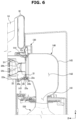
- FIG. 6 is a cross-sectional perspective view of a part of a vacuum cleaner in a state in which the vacuum cleaner is docked onto a docking station in a cleaning apparatus according to an embodiment of the disclosure
- FIG. 7 is a cross-sectional perspective view of a part of a vacuum cleaner when a suction device is driven in a state in which the vacuum cleaner is docked onto the docking station in the cleaning apparatus according to an embodiment of the disclosure.
- the dust collecting chamber 20 may be docked onto the docking station 100 such that the extension axis Y faces in the second direction B. Accordingly, the dust collecting chamber 20 may be docked onto the docking station 100 such that the extension axis Y is arranged in a direction perpendicular to the first direction A, which is the direction of gravity.
- the dust collecting chamber opening 23 may be arranged to be open downward, and the dust collecting chamber door 21 may be arranged at the lower end of the dust collecting chamber 20.
- the dust collecting chamber door 21 may be separated from the body 22 by the gravity and rotate about the rotation shaft 21c in the direction of gravity, causing the dust collecting chamber opening 23 to be opened.
- the dust collecting chamber door 21 may remain closed even when the fixing member 25 is pressed, unless an additional external force is generated.
- the rotation shaft 21c of the dust collecting chamber door 21 is disposed on a side opposite to a side in which the extension pipe 17 is disposed with respect to the extension axis Y of the dust collecting chamber 20 as described, the rotation shaft 21c may be provided to be disposed on the upper end of the dust collecting chamber 20 in the first direction A when the cleaner 10 is docked onto the docking station 100, so that the dust collecting chamber door 21 may remain closed without being affected by the gravity even in an openable state.
- the dust collecting chamber door 21 may maintain a closed state even when the fixing member 25 is pressed inside the docking part 140 in the docked state of the dust collecting chamber 20.
- the docking part 140 may include an opening guide 145 provided to press the push portion 25a when the dust collecting chamber 20 is seated in the seating space 142 through the docking opening 143 so that the dust collecting chamber door 21 is set into an openable state.
- the opening guide 145 may be arranged on a front inner circumferential surface 144 arranged on the front side of the seating space 142 in the second direction B and forming the docking opening 143 at a position of the seating space 142 in which the docking opening 143 is connected.
- the opening guide 145 may be formed as a partial area of the front inner circumferential surface 144 according to the embodiment of the disclosure. However, the disclosure is not limited thereto, and the opening guide 145 may be provided as a region or protruding surface protruding from the front inner circumferential surface 144 toward the center, or in the shape of a protrusion, a rib and the like protruding toward the center from the inner circumferential surface.
- the front inner circumferential surface 144 may be provided to have a size substantially corresponding to that of an outer circumferential surface of the body 22.
- the circumference of the inner circumferential surface of the docking opening 143 and the circumference of the dust collecting chamber body 22 may be provided to substantially the same.
- the front inner circumferential surface 144 and the outer circumferential surface of the body 22 may be provided to face each other at a predetermined distance therebetween.
- the dust collecting chamber 20 may have the outer circumferential surface of the body 22 moved along the front inner circumferential surface 144 in the second direction B.
- the push portion 25a protruding outward from the outer circumferential surface of the body 22 may be pressed against the opening guide 145.
- the push portion 25a disposed on the outside of the outer circumferential surface of the body 22 is pressed in the first direction A by the opening guide 145, which causes the push portion 25a to rotate opposite to the radial direction of the outer circumferential surface of the body 22, so that the hook coupling between the hook portion 25b and the coupling protrusion 21a is released, thereby setting the dust collecting chamber door 21 into an openable state.
- the dust collecting chamber door 21 is maintained in an openable state without being opened unless an additional external force is generated.
- the dust collecting chamber 20 may include a gasket 26 on the dust collecting chamber door 21 to seal a space between the dust collecting chamber door 21 and an inner circumferential surface 22a of the body 22.
- the gasket 26 may be formed of an elastic material, such as rubber, to seal a space between the inner circumferential surface 22a of the body 22 and the dust collecting chamber door 21 to prevent foreign substances collected in the dust collecting chamber 20 from being scattered to the outside.
- the gasket 26 is formed of an elastic material, the gasket 26 may be biased toward the inner circumferential surface 22a of the body 22 when the dust collecting chamber door 21 is in a closed state.
- the gasket 26 is biased in the radial direction of the body 22 with respect to the center of the body 22, so that when there is no external force on the dust collecting chamber door 21, the gasket 26 may elastically support the dust collecting chamber door 21 to prevent the dust collecting chamber door 21 from being opened from the body 22.
- the suction air current provides the dust collecting chamber door 21 with an external force in a direction to open the dust collecting chamber door 21 so that the dust collecting chamber door 21 is opened and the foreign substances collected in the dust collecting chamber 20 are caused to flow into the collecting part 150 through the seating space 142 and thus collected in the collecting part 150.
- the seating space 142 may be provided to allow the dust collecting chamber 20 to be inserted thereinto and allow the dust collecting chamber door 21 to be rotated inside the seating space 142.
- the docking part 140 may include a flow path guide 145 disposed on the opposite side to the docking opening 143 in the second direction B in the seating space 142 and formed in a curved surface.
- the flow path guide may be provided in a curved shape in which the flow guide connected to extend in the second direction B is connected to extend in the first direction A.
- the suction air current generated by the suction device 130 and flowing toward the dust collecting chamber 20 may collide with a portion in which the first direction A and the second direction B cross each other, which causes noise or pressure loss.
- the flow path guide 145 may be formed on the opposite side to the docking opening 143 in the second direction B in the seating space 142, which is a portion in which the first direction A and the second direction B cross each other, to guide the suction air current such that the suction air current flowing in the first direction A is caused to flow in the second direction B smoothly, or vice versa.
- FIG. 8 is a cross-sectional perspective view of a part of a vacuum cleaner before the vacuum cleaner is docked onto a docking station in a cleaning apparatus according to another embodiment of the disclosure.
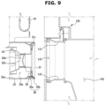
- FIG. 9 is a cross-sectional perspective view of a part of a vacuum cleaner before the vacuum cleaner is docked onto a docking station in a cleaning apparatus according to another embodiment of the disclosure.
- the dust collecting chamber 20 may include an elastic member 27 disposed on the rotation shaft 21c of the dust collecting chamber door 21.
- the elastic member 27 may be provided in the same shape as a torsion spring.
- the elastic member 27 may be provided for the dust collecting chamber door 21 to be biased toward the body 22.
- the dust collecting chamber door 21 even when the dust collecting chamber door 21 is set into an openable state by the fixing member 25 of the dust collecting chamber 20 being pressed, the dust collecting chamber door 21, which is elastically supported by the elastic member 27, may remain closed unless an external force is generated.
- the suction air current when a suction air current is generated by the suction device 130, the suction air current provides the dust collecting chamber door 21 with an external force in a direction to open the dust collecting chamber door 21 so that the dust collecting chamber door 21 is opened and the foreign substances collected in the dust collecting container 20 are caused to flow into the collecting part 150 through the seating space 142 and thus collected in the collecting part 150.
- the dust collecting chamber 20 may include a pair of magnetic members 28 disposed on the body 22 and the dust collecting chamber door 21, respectively.
- a first magnetic member 28a of the pair of magnetic members 28 may be disposed on the body 22, and a second magnetic member 28b of the pair of magnetic members 28 may be disposed on the dust collecting chamber door 21.
- the dust collecting chamber door 21 even when the dust collecting chamber door 21 is set into an openable state by the fixing member 25 of the dust collecting chamber 20 being pressed, the dust collecting chamber door 21, which is magnetically supported by the pair of magnetic members 28, may remain closed unless an external force is generated.
- the suction air current when a suction air current is generated by the suction device 130, the suction air current provides the dust collecting chamber door 21 with an external force in a direction to open the dust collecting chamber door 21 so that the dust collecting chamber door 21 is opened and the foreign substances collected in the dust collecting container 20 are caused to flow into the collecting part 150 through the seating space 142 and thus collected in the collecting part 150.
- FIG. 10 is a cross-sectional perspective view of a part of a vacuum cleaner in a state in which the vacuum cleaner is docked onto a docking station in a cleaning apparatus according to another embodiment of the disclosure
- FIG. 11 is a cross-sectional perspective view of a part of a vacuum cleaner docked onto a docking station with an opening guide driven in a cleaning apparatus according to another embodiment of the disclosure; Since the fixing member 25 is pressed in response to the dust collecting chamber 20 being docked onto the docking station state 1000, the dust collecting door 21 may be maintained in an openable state. In this case, as described above, when there is no external force on the dust collecting chamber door 21, the dust collecting chamber door 21 is not opened.
- the external force is applied to the dust collecting chamber door 21 so that the dust collecting chamber door 21 may be opened and foreign substances collected in the dust collecting chamber 20 may be scattered to the outside.
- the dust collecting chamber door 21 is opened by an external force other than the suction air current in a state in which the suction device 130 is not driven, the foreign substances collected in the dust collecting chamber 20 may be scattered to the outside of the docking station 100.
- the docking station 100 may be provided to, when the cleaner 10 is docked, perform both a charging mode of charging the battery 16 of the cleaner 10 and a suction mode of driving the suction device 130 to discharge foreign substances inside the dust collecting chamber 20, or perform one of a charging mode and a suction mode.
- the user may control the docking station 100 so that, when the cleaner 10 is docked onto the docking station 100, only the charging mode is performed.
- the dust collecting chamber door 21 is opened in a state in which the suction mode is not in operation, foreign substances may be scattered to the outside.
- the docking station 100 may include an opening guide 147 allowing the fixing member 25 of the docked dust collecting chamber 20 to be pressed only when the suction device 130 is driven.
- the opening guide 147 may be provided in the shape of a protrusion or a rib protruding toward the center of the front inner circumferential surface 144 from the front inner circumferential surface 144.
- the opening guide 147 when the dust collecting chamber 20 is inserted into the docking part 140 through the docking opening 143 and docked, may be disposed at an inner side of the docking part 140 in the second direction B from the fixing member 25 of the dust collecting chamber 20.
- the opening guide 147 may be provided to prevent the fixing member 25 from being pressed in a state in which the dust collecting chamber 20 is docked.
- the fixing member 25 is not pressed even when the dust collecting chamber 20 is docked onto the docking part 140, the dust collecting chamber door 21 is prevented from being opened by an external force.
- the docking part 140 may include a driving device 148 interworking with the opening guide 147 to drive the opening guide 147.
- the driving device 148 may drive the opening guide 147 to translate the opening guide 147 in the second direction B according to a signal from the controller (not shown) of the docking station 100.
- the driving device 148 may, upon receiving a signal from the controller (not shown) of the docking station 100 when the suction device 130 is driven, drive the opening guide 147 to be moved forward in the second direction B.
- the driving device 148 may be provided in various configurations, such as a motor, a solenoid valve, and the like.
- the opening guide 147 may be provided to press the fixing member 25, causing the dust collecting chamber door 21 to be set into an openable state.
- the opening guide 147 and the driving device 148 may allow the fixing member 25 to be selectively pressed so that the dust collecting chamber door 21 is opened only when the suction device 130 is driven. Accordingly, foreign substances collected in the dust collecting chamber 20 are prevented from being unintentionally scattered to the outside.
- the driving device 148 may be provided to be directly controlled by the user. That is, in addition to control of the controller (not shown) of the docking station 100 according to the driving of the suction device 130, the user may separately input a signal for driving the driving device 148 to drive the driving device 148.
- the user may input a driving signal of the driving device 148 to the controller (not shown) of the docking station 100, so that the user may control the driving device 148 separately from driving of the suction device 130.
- the disclosure is not limited thereto, and in order for the user to directly move the opening guide 147 using a physical force through an intermediate member (not shown) provided to interwork with the opening guide 147, the disclosure may include a push button (not shown) and the like interworking with the intermediate member (not shown).
- the push button (not shown) may be disposed on one side of the body housing 110 to allow a user to easily open the dust collecting chamber door 21 through the opening guide 147.
- a cleaning apparatus 1 according to another embodiment of the disclosure will be described.
- the components for the embodiment except a docking station are the same as those of the cleaning apparatus according to the embodiment described above, and therefore a description thereof will be omitted.
- FIG. 12 is a view illustrating a state in which a vacuum cleaner of a cleaning apparatus according to another embodiment of the disclosure is docked onto a docking station.
- the docking surface 211 may be provided to extend in a direction inclined with respect to the first direction A, which is an upper and lower side direction.
- the cleaner 10 may be docked onto the docking station 200 in a direction perpendicular to a direction in which the long axis of the docking surface 211 extends in the docking station 200.
- the cleaner 10 may be provided to be docked onto the docking station 200 in the fourth direction E perpendicular to the third direction D.
- the direction in which the cleaner 10 is docked onto the docking station 200 is provided in the fourth direction E oblique with respect to the second direction B, which is the horizontal direction, the user may easily dock the cleaner 10 onto the docking station 200.
Landscapes
- Engineering & Computer Science (AREA)
- Mechanical Engineering (AREA)
- Robotics (AREA)
- Electric Vacuum Cleaner (AREA)
Claims (15)
- Reinigungsgerät (1), umfassend:einen Staubsauger (10) beinhaltend eine Batterie (16), die dazu konfiguriert ist, eine Ansaugkraft zu erzeugen, und eine Staubsammelkammer (20), in der durch die Ansaugkraft angesaugte Fremdstoffe gesammelt werden; undeine Andockstation (100), die mit dem Staubsauger verbunden ist und eine Längsachse aufweist, die sich in einer ersten Richtung (A) erstreckt,wobei die Andockstation beinhaltet:einen Ladeteil (120), der dazu vorgesehen ist, mit der Batterie in Kontakt zu kommen, um die Batterie aufzuladen;dadurch gekennzeichnet, dass die Andockstation ferner beinhaltet:einen Andockteil (140), der mit der Staubsammelkammer verbunden ist, um in der Staubsammelkammer gesammelte Fremdstoffe zu entfernen; undeine Ansaugvorrichtung (130), die dazu konfiguriert ist, die Fremdstoffe und die Innenluft in der an den Andockteil angedockten Staubsammelkammer anzusaugen,wobei der Andockteil eine Andocköffnung (143) beinhaltet, die in einer zweiten Richtung (B) geöffnet ist, die sich von der ersten Richtung (A) so unterscheidet, dass zumindest ein Abschnitt der Staubsammelkammer (20) in die Andocköffnung eingesetzt wird.
- Reinigungsgerät nach Anspruch 1, wobei der Ladeteil (120) in der ersten Richtung (A) oberhalb des Andockteils (140) angeordnet ist.
- Reinigungsgerät nach Anspruch 1, wobei die erste Richtung (A) in einer Richtung vorgesehen ist, die einer Oberseiten- und Unterseitenrichtung der Andockstation (100) entspricht, und die zweite Richtung (B) in einer Richtung vorgesehen ist, die im Wesentlichen senkrecht zur ersten Richtung verläuft.
- Reinigungsgerät nach Anspruch 1, wobei die erste Richtung (A) in einer Richtung vorgesehen ist, die einer Oberseiten- und Unterseitenrichtung der Andockstation (100) entspricht, und die zweite Richtung (B) in einer Richtung vorgesehen ist, die in Bezug auf die erste Richtung geneigt ist.
- Reinigungsgerät nach Anspruch 1, wobei die Staubsammelkammer (20) einen Körper (22) beinhaltet, der in einer zylindrischen Form vorgesehen ist, die um eine Erstreckungsachse (Y) geformt ist, die sich in eine Richtung erstreckt, und
dazu vorgesehen ist, in einer Erstreckungsrichtung der Erstreckungsachse der Staubsammelkammer in das Andockteil eingesetzt zu werden. - Reinigungsgerät nach Anspruch 5, wobei der Staubsauger ferner beinhaltet: eine Ansaugeinheit (18), die dazu konfiguriert ist, Fremdstoffe anzusaugen; und ein Verlängerungsrohr (17), das die Ansaugeinheit und die Staubsammelkammer (20) miteinander verbindet und eine Längsachse (X) aufweist, die sich in eine Richtung erstreckt, und
die Längsachse (X) des Verlängerungsrohrs und die Erstreckungsachse (Y) der Staubsammelkammer dazu vorgesehen sind, im Wesentlichen senkrecht zueinander zu stehen. - Reinigungsgerät nach Anspruch 1, wobei der Staubsauger ferner beinhaltet: eine Ansaugeinheit (18), die dazu konfiguriert ist, Fremdstoffe anzusaugen; und ein Verlängerungsrohr (17), das die Ansaugeinheit und die Staubsammelkammer (20) miteinander verbindet und eine Längsachse (X) aufweist, die sich in eine Richtung erstreckt, und
während die Staubsammelkammer an das Andockteil (140) angedockt ist, der Staubsauger so auf der Andockstation (100) abgestützt wird, dass sich die Längsachse (X) des Verlängerungsrohrs in eine Richtung erstreckt, die der ersten Richtung (A) entspricht. - Reinigungsgerät nach Anspruch 5, wobei die Staubsammelkammer (20) ferner beinhaltet: eine Staubsammelkammeröffnung (23), die in einer Richtung geöffnet ist, die der Erstreckungsrichtung der Erstreckungsachse (Y) des Körpers entspricht und an einem Ende des Körpers gebildet ist; und eine Staubsammelkammertür, die dazu konfiguriert ist, die Staubsammelkammeröffnung zu öffnen und zu schließen, und
während die Staubsammelkammer in die Andocköffnung (143) eingesetzt wird, die Staubsammelkammertür dazu vorgesehen ist, innerhalb des Andockteils angeordnet zu werden. - Reinigungsgerät nach Anspruch 8, wobei die Staubsammelkammer (20) ferner ein Befestigungselement (25) beinhaltet, das dazu vorgesehen ist, die Staubsammelkammertür (21) am Körper zu befestigen und bei Druck durch eine äußere Kraft die Befestigung der Staubsammelkammertür zu lösen, und
das Andockteil (140) dazu konfiguriert ist, das Befestigungselement als Reaktion auf das Einsetzen der Staubsammelkammer in die Andocköffnung (143) zu drücken. - Reinigungsgerät nach Anspruch 9, wobei das Andockteil (140) eine Öffnungsführung beinhaltet, die dazu konfiguriert ist, das Befestigungselement als Reaktion auf das Einsetzen der Staubsammelkammer in die Andocköffnung zu drücken.
- Reinigungsgerät nach Anspruch 9, wobei die Staubsammelkammertür (21) dazu vorgesehen ist, sich um eine Drehwelle (21c) zu drehen, die an einer Seite eines Endes des Körpers angeordnet ist, und
die Staubsammelkammer (20) derart vorgesehen ist, dass, wenn die Staubsammelkammer in die Andocköffnung eingesetzt wird, die Drehwelle an einem in der ersten Richtung oberen Ende der Staubsammelkammer angeordnet wird. - Reinigungsgerät nach Anspruch 11, wobei die Staubsammelkammer (20) ferner ein elastisches Element (27) beinhaltet, das in einer Erstreckungsrichtung der Drehwelle (21c) angeordnet ist, damit die Staubsammelkammertür in eine Richtung zum Körper hin vorgespannt wird.
- Reinigungsgerät nach Anspruch 11, wobei die Staubsammelkammer (20) ferner ein Paar magnetische Elemente (28) beinhaltet, die jeweils am Körper und an der Staubsammelkammertür angeordnet sind.
- Reinigungsgerät nach Anspruch 11, wobei die Staubsammelkammertür (21) dazu vorgesehen ist, um die Drehwelle durch einen in der Ansaugvorrichtung gebildeten Ansaugluftstrom gedreht zu werden, wenn die Ansaugvorrichtung angetrieben wird.
- Reinigungsgerät nach Anspruch 1, wobei die Andockstation (100) ferner einen Sammelteil (150) beinhaltet, der dazu konfiguriert ist, Fremdstoffe innerhalb der Staubsammelkammer zu sammeln, die durch einen von der Ansaugvorrichtung gebildeten Ansaugluftstrom strömen,
wobei der Ladeteil, der Andockteil, der Sammelteil und die Ansaugvorrichtung in der ersten Richtung nacheinander arrangiert sind.
Priority Applications (1)
| Application Number | Priority Date | Filing Date | Title |
|---|---|---|---|
| EP24205675.2A EP4467051A3 (de) | 2020-07-03 | 2021-05-12 | Reinigungsvorrichtung mit staubsauger und andockstation |
Applications Claiming Priority (2)
| Application Number | Priority Date | Filing Date | Title |
|---|---|---|---|
| KR1020200082178A KR102566393B1 (ko) | 2020-07-03 | 2020-07-03 | 진공 청소기와 도킹 스테이션을 포함하는 청소 장치 |
| PCT/KR2021/005933 WO2022005013A1 (ko) | 2020-07-03 | 2021-05-12 | 진공 청소기와 도킹 스테이션을 포함하는 청소 장치 |
Related Child Applications (2)
| Application Number | Title | Priority Date | Filing Date |
|---|---|---|---|
| EP24205675.2A Division EP4467051A3 (de) | 2020-07-03 | 2021-05-12 | Reinigungsvorrichtung mit staubsauger und andockstation |
| EP24205675.2A Division-Into EP4467051A3 (de) | 2020-07-03 | 2021-05-12 | Reinigungsvorrichtung mit staubsauger und andockstation |
Publications (4)
| Publication Number | Publication Date |
|---|---|
| EP4154786A1 EP4154786A1 (de) | 2023-03-29 |
| EP4154786A4 EP4154786A4 (de) | 2023-12-27 |
| EP4154786C0 EP4154786C0 (de) | 2024-11-20 |
| EP4154786B1 true EP4154786B1 (de) | 2024-11-20 |
Family
ID=74128868
Family Applications (2)
| Application Number | Title | Priority Date | Filing Date |
|---|---|---|---|
| EP21831600.8A Active EP4154786B1 (de) | 2020-07-03 | 2021-05-12 | Reinigungsvorrichtung mit staubsauger und andockstation |
| EP24205675.2A Pending EP4467051A3 (de) | 2020-07-03 | 2021-05-12 | Reinigungsvorrichtung mit staubsauger und andockstation |
Family Applications After (1)
| Application Number | Title | Priority Date | Filing Date |
|---|---|---|---|
| EP24205675.2A Pending EP4467051A3 (de) | 2020-07-03 | 2021-05-12 | Reinigungsvorrichtung mit staubsauger und andockstation |
Country Status (6)
| Country | Link |
|---|---|
| US (1) | US20230146588A1 (de) |
| EP (2) | EP4154786B1 (de) |
| KR (5) | KR102566393B1 (de) |
| CN (1) | CN115734735A (de) |
| ES (1) | ES2999326T3 (de) |
| WO (1) | WO2022005013A1 (de) |
Families Citing this family (39)
| Publication number | Priority date | Publication date | Assignee | Title |
|---|---|---|---|---|
| KR20220000297A (ko) * | 2020-06-25 | 2022-01-03 | 삼성전자주식회사 | 도킹 스테이션, 이동 로봇 및 도킹 스테이션과 이동 로봇을 제어하는 이동 로봇 관리 시스템 |
| KR102566393B1 (ko) * | 2020-07-03 | 2023-08-14 | 삼성전자주식회사 | 진공 청소기와 도킹 스테이션을 포함하는 청소 장치 |
| KR20220046312A (ko) * | 2020-10-07 | 2022-04-14 | 엘지전자 주식회사 | 청소기 스테이션 및 이를 포함하는 청소기 시스템과, 청소기 시스템을 이용한 잔여 먼지 제거 방법 |
| KR102406189B1 (ko) | 2020-10-07 | 2022-06-10 | 엘지전자 주식회사 | 청소기 시스템 |
| KR102440910B1 (ko) * | 2021-01-13 | 2022-09-07 | 엘지전자 주식회사 | 청소기 스테이션, 청소기 시스템 및 그 제어방법 |
| KR20220115253A (ko) * | 2021-02-10 | 2022-08-17 | 삼성전자주식회사 | 진공 청소기와 도킹 스테이션을 포함하는 청소 장치 |
| KR102938611B1 (ko) | 2021-02-17 | 2026-03-12 | 엘지전자 주식회사 | 청소기 스테이션 |
| KR20220127060A (ko) * | 2021-03-10 | 2022-09-19 | 삼성전자주식회사 | 청소기와 도킹 스테이션을 포함하는 청소 장치 |
| CN112971625A (zh) * | 2021-04-19 | 2021-06-18 | 上海耐柯环保科技有限公司 | 一种机器人用吸尘器 |
| KR102792001B1 (ko) | 2021-06-23 | 2025-04-08 | 엘지전자 주식회사 | 청소기 스테이션 |
| US12433461B2 (en) | 2022-07-05 | 2025-10-07 | Sharkninja Operating Llc | Vacuum cleaner |
| US20230043567A1 (en) | 2021-08-03 | 2023-02-09 | Sharkninja Operating Llc | Surface cleaning device with odor management |
| KR20230022476A (ko) * | 2021-08-09 | 2023-02-16 | 삼성전자주식회사 | 청소기와 도킹 스테이션을 포함하는 청소 장치 |
| KR102376262B1 (ko) * | 2021-08-30 | 2022-03-21 | (주) 캐치웰 | 자동으로 전력 충전 및 먼지 비움이 가능한 청소 장치 |
| CN113693482B (zh) * | 2021-09-13 | 2025-02-18 | 广东一沐科技有限公司 | 一种手持无线集尘吸尘器 |
| CN220144215U (zh) | 2021-11-05 | 2023-12-08 | 尚科宁家运营有限公司 | 表面清洁装置 |
| US12532998B2 (en) | 2021-11-22 | 2026-01-27 | Samsung Electronics Co., Ltd. | Cleaning device having vacuum cleaner and dust collecting station |
| KR20230089398A (ko) | 2021-12-13 | 2023-06-20 | 엘지전자 주식회사 | 청정기모듈을 포함하는 청소기용 먼지 수거장치 및 청정기모듈 |
| KR20230089403A (ko) | 2021-12-13 | 2023-06-20 | 엘지전자 주식회사 | 청소기용 먼지 수거장치 및 그의 제어방법 |
| KR20230089401A (ko) | 2021-12-13 | 2023-06-20 | 엘지전자 주식회사 | 청소기용 먼지 수거장치 |
| KR20230089402A (ko) | 2021-12-13 | 2023-06-20 | 엘지전자 주식회사 | 청소기용 먼지 수거장치 |
| KR20230089397A (ko) | 2021-12-13 | 2023-06-20 | 엘지전자 주식회사 | 청소기용 먼지 수거장치 |
| KR20230089620A (ko) | 2021-12-13 | 2023-06-21 | 엘지전자 주식회사 | 청소기용 먼지 수거장치 |
| KR102940483B1 (ko) | 2021-12-13 | 2026-03-17 | 엘지전자 주식회사 | 청소기용 먼지 수거장치 |
| KR20230089399A (ko) | 2021-12-13 | 2023-06-20 | 엘지전자 주식회사 | 청소기용 먼지 수거장치 |
| KR20230089400A (ko) | 2021-12-13 | 2023-06-20 | 엘지전자 주식회사 | 청소기용 먼지 수거장치 |
| WO2023113225A1 (ko) * | 2021-12-13 | 2023-06-22 | 삼성전자 주식회사 | 집진 장치, 진공 청소기 및 청소 장치 |
| KR102672230B1 (ko) * | 2022-03-11 | 2024-06-05 | 엘지전자 주식회사 | 청소기 스테이션 |
| EP4434425A4 (de) | 2022-05-31 | 2025-10-22 | Samsung Electronics Co Ltd | Stationsvorrichtung und betriebsverfahren der stationsvorrichtung |
| EP4627988A4 (de) * | 2023-03-16 | 2026-03-18 | Samsung Electronics Co Ltd | Staubsammler, staubsauger und reinigungsvorrichtung |
| KR20250166243A (ko) * | 2023-04-20 | 2025-11-27 | 샤크닌자 오퍼레이팅 엘엘씨 | 진공 청소기 |
| CN119326321A (zh) * | 2023-07-19 | 2025-01-21 | 江苏美的清洁电器股份有限公司 | 清洁系统 |
| US20250057373A1 (en) * | 2023-08-14 | 2025-02-20 | Omachron Intellectual Property Inc. | Surface cleaning apparatus and docking station usable therewith |
| KR20250046721A (ko) * | 2023-09-27 | 2025-04-03 | 엘지전자 주식회사 | 청소기 스테이션 |
| KR20250078059A (ko) * | 2023-11-24 | 2025-06-02 | 엘지전자 주식회사 | 청소기 스테이션 |
| KR102715272B1 (ko) | 2024-04-30 | 2024-10-11 | 주식회사 미래가디언 | 먼지 자동 비움이 가능한 무선 청소장치 |
| WO2025241624A1 (zh) * | 2024-05-24 | 2025-11-27 | 广东德尔玛健康科技有限公司 | 集尘站及吸尘器系统 |
| CN223009029U (zh) * | 2024-06-14 | 2025-06-24 | 东芝生活电器株式会社 | 电动吸尘器装置 |
| GB2643424A (en) * | 2024-08-14 | 2026-02-18 | Dyson Technology Ltd | Vacuum cleaner system |
Family Cites Families (17)
| Publication number | Priority date | Publication date | Assignee | Title |
|---|---|---|---|---|
| KR20060107624A (ko) * | 2005-04-11 | 2006-10-16 | 엘지전자 주식회사 | 진공청소기의 집진유니트 |
| KR20070074146A (ko) * | 2006-01-06 | 2007-07-12 | 삼성전자주식회사 | 청소기 시스템 |
| EP2027806A1 (de) * | 2006-04-04 | 2009-02-25 | Samsung Electronics Co., Ltd. | Roboterreinigungssystem mit Roboterreiniger und Andockstation |
| KR101330734B1 (ko) * | 2007-08-24 | 2013-11-20 | 삼성전자주식회사 | 로봇청소기와 도킹 스테이션을 구비하는 로봇청소기 시스템 |
| IL228523A0 (en) * | 2013-09-17 | 2014-03-31 | Nds Ltd | Processing private data in a cloud-based environment |
| JP6119915B2 (ja) * | 2014-02-27 | 2017-04-26 | 三菱電機株式会社 | 電気掃除機 |
| DE102014119191A1 (de) * | 2014-12-19 | 2016-06-23 | Vorwerk & Co. Interholding Gmbh | Basisstation für einen Staubsauger |
| WO2017047291A1 (ja) * | 2015-09-14 | 2017-03-23 | 東芝ライフスタイル株式会社 | 電気掃除装置 |
| WO2017196027A1 (ko) * | 2016-05-09 | 2017-11-16 | 엘지전자 주식회사 | 청소기 거치대 |
| KR102626404B1 (ko) * | 2016-05-09 | 2024-01-18 | 엘지전자 주식회사 | 청소기의 충전대 및 청소기의 거치대 |
| US10464746B2 (en) * | 2016-12-28 | 2019-11-05 | Omachron Intellectual Property Inc. | Dust and allergen control for surface cleaning apparatus |
| KR102453842B1 (ko) * | 2017-01-03 | 2022-10-14 | 삼성전자주식회사 | 핸디-스틱형 진공청소기 |
| KR102519650B1 (ko) * | 2017-03-03 | 2023-04-10 | 엘지전자 주식회사 | 청소기의 지지기구, 청소기 유닛 |
| DE202018103929U1 (de) * | 2018-07-10 | 2018-07-18 | New Icon Development Limited | Kombination aus einem Handstaubsauger und einer Aufnahmestation |
| KR20200073966A (ko) * | 2018-12-14 | 2020-06-24 | 삼성전자주식회사 | 진공 청소기와 도킹 스테이션을 포함하는 청소 장치 |
| KR102166773B1 (ko) * | 2018-12-14 | 2020-10-16 | 삼성전자주식회사 | 진공 청소기와 도킹 스테이션을 포함하는 청소 장치 |
| KR102566393B1 (ko) * | 2020-07-03 | 2023-08-14 | 삼성전자주식회사 | 진공 청소기와 도킹 스테이션을 포함하는 청소 장치 |
-
2020
- 2020-07-03 KR KR1020200082178A patent/KR102566393B1/ko active Active
-
2021
- 2021-05-12 EP EP21831600.8A patent/EP4154786B1/de active Active
- 2021-05-12 ES ES21831600T patent/ES2999326T3/es active Active
- 2021-05-12 WO PCT/KR2021/005933 patent/WO2022005013A1/ko not_active Ceased
- 2021-05-12 EP EP24205675.2A patent/EP4467051A3/de active Pending
- 2021-05-12 CN CN202180046785.4A patent/CN115734735A/zh active Pending
-
2022
- 2022-01-24 KR KR1020220010213A patent/KR102470035B1/ko active Active
- 2022-12-28 US US18/089,993 patent/US20230146588A1/en active Pending
-
2023
- 2023-08-08 KR KR1020230103476A patent/KR20230121703A/ko not_active Ceased
-
2024
- 2024-08-08 KR KR1020240106392A patent/KR102809917B1/ko active Active
-
2025
- 2025-05-14 KR KR1020250062854A patent/KR20250077406A/ko active Pending
Also Published As
| Publication number | Publication date |
|---|---|
| KR20240127317A (ko) | 2024-08-22 |
| KR20220016265A (ko) | 2022-02-08 |
| EP4154786A1 (de) | 2023-03-29 |
| EP4154786A4 (de) | 2023-12-27 |
| WO2022005013A1 (ko) | 2022-01-06 |
| EP4467051A2 (de) | 2024-11-27 |
| KR102470035B1 (ko) | 2022-11-25 |
| CN115734735A (zh) | 2023-03-03 |
| EP4467051A3 (de) | 2025-02-26 |
| KR20230121703A (ko) | 2023-08-21 |
| KR102566393B1 (ko) | 2023-08-14 |
| US20230146588A1 (en) | 2023-05-11 |
| KR20210002057A (ko) | 2021-01-06 |
| ES2999326T3 (en) | 2025-02-25 |
| EP4154786C0 (de) | 2024-11-20 |
| KR102809917B1 (ko) | 2025-05-22 |
| KR20250077406A (ko) | 2025-05-30 |
Similar Documents
| Publication | Publication Date | Title |
|---|---|---|
| EP4154786B1 (de) | Reinigungsvorrichtung mit staubsauger und andockstation | |
| US12239281B2 (en) | Cleaning apparatus having vacuum cleaner and docking station | |
| EP4169428B1 (de) | Reinigungsvorrichtung mit staubsauger und andockstation und steuerungsverfahren dafür | |
| EP3893709B1 (de) | Roboterreiniger | |
| EP2392244B1 (de) | Tragbarer Stockstaubsauger | |
| KR20220115253A (ko) | 진공 청소기와 도킹 스테이션을 포함하는 청소 장치 | |
| KR102938611B1 (ko) | 청소기 스테이션 | |
| JP7538758B2 (ja) | 掃除システム | |
| WO2023286294A1 (ja) | 掃除システム及び電気掃除機を載置するスタンド | |
| JP2022146259A (ja) | 電気掃除機 |
Legal Events
| Date | Code | Title | Description |
|---|---|---|---|
| STAA | Information on the status of an ep patent application or granted ep patent |
Free format text: STATUS: THE INTERNATIONAL PUBLICATION HAS BEEN MADE |
|
| PUAI | Public reference made under article 153(3) epc to a published international application that has entered the european phase |
Free format text: ORIGINAL CODE: 0009012 |
|
| STAA | Information on the status of an ep patent application or granted ep patent |
Free format text: STATUS: REQUEST FOR EXAMINATION WAS MADE |
|
| 17P | Request for examination filed |
Effective date: 20221221 |
|
| AK | Designated contracting states |
Kind code of ref document: A1 Designated state(s): AL AT BE BG CH CY CZ DE DK EE ES FI FR GB GR HR HU IE IS IT LI LT LU LV MC MK MT NL NO PL PT RO RS SE SI SK SM TR |
|
| DAV | Request for validation of the european patent (deleted) | ||
| DAX | Request for extension of the european patent (deleted) | ||
| A4 | Supplementary search report drawn up and despatched |
Effective date: 20231124 |
|
| RIC1 | Information provided on ipc code assigned before grant |
Ipc: A47L 9/10 20060101ALI20231120BHEP Ipc: A47L 9/16 20060101ALI20231120BHEP Ipc: A47L 9/28 20060101AFI20231120BHEP |
|
| GRAP | Despatch of communication of intention to grant a patent |
Free format text: ORIGINAL CODE: EPIDOSNIGR1 |
|
| STAA | Information on the status of an ep patent application or granted ep patent |
Free format text: STATUS: GRANT OF PATENT IS INTENDED |
|
| INTG | Intention to grant announced |
Effective date: 20240618 |
|
| GRAS | Grant fee paid |
Free format text: ORIGINAL CODE: EPIDOSNIGR3 |
|
| GRAA | (expected) grant |
Free format text: ORIGINAL CODE: 0009210 |
|
| STAA | Information on the status of an ep patent application or granted ep patent |
Free format text: STATUS: THE PATENT HAS BEEN GRANTED |
|
| AK | Designated contracting states |
Kind code of ref document: B1 Designated state(s): AL AT BE BG CH CY CZ DE DK EE ES FI FR GB GR HR HU IE IS IT LI LT LU LV MC MK MT NL NO PL PT RO RS SE SI SK SM TR |
|
| REG | Reference to a national code |
Ref country code: GB Ref legal event code: FG4D |
|
| REG | Reference to a national code |
Ref country code: CH Ref legal event code: EP |
|
| REG | Reference to a national code |
Ref country code: DE Ref legal event code: R096 Ref document number: 602021022202 Country of ref document: DE |
|
| REG | Reference to a national code |
Ref country code: IE Ref legal event code: FG4D |
|
| U01 | Request for unitary effect filed |
Effective date: 20241205 |
|
| U07 | Unitary effect registered |
Designated state(s): AT BE BG DE DK EE FI FR IT LT LU LV MT NL PT RO SE SI Effective date: 20241216 |
|
| REG | Reference to a national code |
Ref country code: ES Ref legal event code: FG2A Ref document number: 2999326 Country of ref document: ES Kind code of ref document: T3 Effective date: 20250225 |
|
| PG25 | Lapsed in a contracting state [announced via postgrant information from national office to epo] |
Ref country code: IS Free format text: LAPSE BECAUSE OF FAILURE TO SUBMIT A TRANSLATION OF THE DESCRIPTION OR TO PAY THE FEE WITHIN THE PRESCRIBED TIME-LIMIT Effective date: 20250320 Ref country code: HR Free format text: LAPSE BECAUSE OF FAILURE TO SUBMIT A TRANSLATION OF THE DESCRIPTION OR TO PAY THE FEE WITHIN THE PRESCRIBED TIME-LIMIT Effective date: 20241120 |
|
| PG25 | Lapsed in a contracting state [announced via postgrant information from national office to epo] |
Ref country code: NO Free format text: LAPSE BECAUSE OF FAILURE TO SUBMIT A TRANSLATION OF THE DESCRIPTION OR TO PAY THE FEE WITHIN THE PRESCRIBED TIME-LIMIT Effective date: 20250220 |
|
| PG25 | Lapsed in a contracting state [announced via postgrant information from national office to epo] |
Ref country code: GR Free format text: LAPSE BECAUSE OF FAILURE TO SUBMIT A TRANSLATION OF THE DESCRIPTION OR TO PAY THE FEE WITHIN THE PRESCRIBED TIME-LIMIT Effective date: 20250221 |
|
| PG25 | Lapsed in a contracting state [announced via postgrant information from national office to epo] |
Ref country code: PL Free format text: LAPSE BECAUSE OF FAILURE TO SUBMIT A TRANSLATION OF THE DESCRIPTION OR TO PAY THE FEE WITHIN THE PRESCRIBED TIME-LIMIT Effective date: 20241120 |
|
| PG25 | Lapsed in a contracting state [announced via postgrant information from national office to epo] |
Ref country code: RS Free format text: LAPSE BECAUSE OF FAILURE TO SUBMIT A TRANSLATION OF THE DESCRIPTION OR TO PAY THE FEE WITHIN THE PRESCRIBED TIME-LIMIT Effective date: 20250220 |
|
| U20 | Renewal fee for the european patent with unitary effect paid |
Year of fee payment: 5 Effective date: 20250523 |
|
| PG25 | Lapsed in a contracting state [announced via postgrant information from national office to epo] |
Ref country code: SM Free format text: LAPSE BECAUSE OF FAILURE TO SUBMIT A TRANSLATION OF THE DESCRIPTION OR TO PAY THE FEE WITHIN THE PRESCRIBED TIME-LIMIT Effective date: 20241120 |
|
| PGFP | Annual fee paid to national office [announced via postgrant information from national office to epo] |
Ref country code: ES Payment date: 20250613 Year of fee payment: 5 |
|
| PG25 | Lapsed in a contracting state [announced via postgrant information from national office to epo] |
Ref country code: SK Free format text: LAPSE BECAUSE OF FAILURE TO SUBMIT A TRANSLATION OF THE DESCRIPTION OR TO PAY THE FEE WITHIN THE PRESCRIBED TIME-LIMIT Effective date: 20241120 |
|
| PGFP | Annual fee paid to national office [announced via postgrant information from national office to epo] |
Ref country code: TR Payment date: 20250414 Year of fee payment: 5 |
|
| PG25 | Lapsed in a contracting state [announced via postgrant information from national office to epo] |
Ref country code: CZ Free format text: LAPSE BECAUSE OF FAILURE TO SUBMIT A TRANSLATION OF THE DESCRIPTION OR TO PAY THE FEE WITHIN THE PRESCRIBED TIME-LIMIT Effective date: 20241120 |
|
| PLBE | No opposition filed within time limit |
Free format text: ORIGINAL CODE: 0009261 |
|
| STAA | Information on the status of an ep patent application or granted ep patent |
Free format text: STATUS: NO OPPOSITION FILED WITHIN TIME LIMIT |
|
| 26N | No opposition filed |
Effective date: 20250821 |
|
| REG | Reference to a national code |
Ref country code: CH Ref legal event code: H13 Free format text: ST27 STATUS EVENT CODE: U-0-0-H10-H13 (AS PROVIDED BY THE NATIONAL OFFICE) Effective date: 20251223 |
|
| PG25 | Lapsed in a contracting state [announced via postgrant information from national office to epo] |
Ref country code: CH Free format text: LAPSE BECAUSE OF NON-PAYMENT OF DUE FEES Effective date: 20250531 |
|
| PG25 | Lapsed in a contracting state [announced via postgrant information from national office to epo] |
Ref country code: MC Free format text: LAPSE BECAUSE OF FAILURE TO SUBMIT A TRANSLATION OF THE DESCRIPTION OR TO PAY THE FEE WITHIN THE PRESCRIBED TIME-LIMIT Effective date: 20241120 |
|
| PGFP | Annual fee paid to national office [announced via postgrant information from national office to epo] |
Ref country code: GB Payment date: 20260324 Year of fee payment: 6 |
|
| PG25 | Lapsed in a contracting state [announced via postgrant information from national office to epo] |
Ref country code: IE Free format text: LAPSE BECAUSE OF NON-PAYMENT OF DUE FEES Effective date: 20250512 |