EP4151872B1 - Nichtelliptisches kontaktprofil für ein zylinderrollenlager - Google Patents
Nichtelliptisches kontaktprofil für ein zylinderrollenlager Download PDFInfo
- Publication number
- EP4151872B1 EP4151872B1 EP22175634.9A EP22175634A EP4151872B1 EP 4151872 B1 EP4151872 B1 EP 4151872B1 EP 22175634 A EP22175634 A EP 22175634A EP 4151872 B1 EP4151872 B1 EP 4151872B1
- Authority
- EP
- European Patent Office
- Prior art keywords
- roller
- profile
- contact
- segment
- flange
- Prior art date
- Legal status (The legal status is an assumption and is not a legal conclusion. Google has not performed a legal analysis and makes no representation as to the accuracy of the status listed.)
- Active
Links
Images



Classifications
-
- F—MECHANICAL ENGINEERING; LIGHTING; HEATING; WEAPONS; BLASTING
- F16—ENGINEERING ELEMENTS AND UNITS; GENERAL MEASURES FOR PRODUCING AND MAINTAINING EFFECTIVE FUNCTIONING OF MACHINES OR INSTALLATIONS; THERMAL INSULATION IN GENERAL
- F16C—SHAFTS; FLEXIBLE SHAFTS; ELEMENTS OR CRANKSHAFT MECHANISMS; ROTARY BODIES OTHER THAN GEARING ELEMENTS; BEARINGS
- F16C19/00—Bearings with rolling contact, for exclusively rotary movement
- F16C19/22—Bearings with rolling contact, for exclusively rotary movement with bearing rollers essentially of the same size in one or more circular rows, e.g. needle bearings
- F16C19/34—Bearings with rolling contact, for exclusively rotary movement with bearing rollers essentially of the same size in one or more circular rows, e.g. needle bearings for both radial and axial load
- F16C19/36—Bearings with rolling contact, for exclusively rotary movement with bearing rollers essentially of the same size in one or more circular rows, e.g. needle bearings for both radial and axial load with a single row of rollers
- F16C19/361—Bearings with rolling contact, for exclusively rotary movement with bearing rollers essentially of the same size in one or more circular rows, e.g. needle bearings for both radial and axial load with a single row of rollers with cylindrical rollers
-
- F—MECHANICAL ENGINEERING; LIGHTING; HEATING; WEAPONS; BLASTING
- F16—ENGINEERING ELEMENTS AND UNITS; GENERAL MEASURES FOR PRODUCING AND MAINTAINING EFFECTIVE FUNCTIONING OF MACHINES OR INSTALLATIONS; THERMAL INSULATION IN GENERAL
- F16C—SHAFTS; FLEXIBLE SHAFTS; ELEMENTS OR CRANKSHAFT MECHANISMS; ROTARY BODIES OTHER THAN GEARING ELEMENTS; BEARINGS
- F16C33/00—Parts of bearings; Special methods for making bearings or parts thereof
- F16C33/30—Parts of ball or roller bearings
- F16C33/34—Rollers; Needles
-
- F—MECHANICAL ENGINEERING; LIGHTING; HEATING; WEAPONS; BLASTING
- F16—ENGINEERING ELEMENTS AND UNITS; GENERAL MEASURES FOR PRODUCING AND MAINTAINING EFFECTIVE FUNCTIONING OF MACHINES OR INSTALLATIONS; THERMAL INSULATION IN GENERAL
- F16C—SHAFTS; FLEXIBLE SHAFTS; ELEMENTS OR CRANKSHAFT MECHANISMS; ROTARY BODIES OTHER THAN GEARING ELEMENTS; BEARINGS
- F16C33/00—Parts of bearings; Special methods for making bearings or parts thereof
- F16C33/30—Parts of ball or roller bearings
- F16C33/34—Rollers; Needles
- F16C33/36—Rollers; Needles with bearing-surfaces other than cylindrical, e.g. tapered; with grooves in the bearing surfaces
-
- F—MECHANICAL ENGINEERING; LIGHTING; HEATING; WEAPONS; BLASTING
- F16—ENGINEERING ELEMENTS AND UNITS; GENERAL MEASURES FOR PRODUCING AND MAINTAINING EFFECTIVE FUNCTIONING OF MACHINES OR INSTALLATIONS; THERMAL INSULATION IN GENERAL
- F16C—SHAFTS; FLEXIBLE SHAFTS; ELEMENTS OR CRANKSHAFT MECHANISMS; ROTARY BODIES OTHER THAN GEARING ELEMENTS; BEARINGS
- F16C33/00—Parts of bearings; Special methods for making bearings or parts thereof
- F16C33/30—Parts of ball or roller bearings
- F16C33/58—Raceways; Race rings
-
- F—MECHANICAL ENGINEERING; LIGHTING; HEATING; WEAPONS; BLASTING
- F16—ENGINEERING ELEMENTS AND UNITS; GENERAL MEASURES FOR PRODUCING AND MAINTAINING EFFECTIVE FUNCTIONING OF MACHINES OR INSTALLATIONS; THERMAL INSULATION IN GENERAL
- F16C—SHAFTS; FLEXIBLE SHAFTS; ELEMENTS OR CRANKSHAFT MECHANISMS; ROTARY BODIES OTHER THAN GEARING ELEMENTS; BEARINGS
- F16C33/00—Parts of bearings; Special methods for making bearings or parts thereof
- F16C33/30—Parts of ball or roller bearings
- F16C33/58—Raceways; Race rings
- F16C33/583—Details of specific parts of races
- F16C33/585—Details of specific parts of races of raceways, e.g. ribs to guide the rollers
-
- F—MECHANICAL ENGINEERING; LIGHTING; HEATING; WEAPONS; BLASTING
- F16—ENGINEERING ELEMENTS AND UNITS; GENERAL MEASURES FOR PRODUCING AND MAINTAINING EFFECTIVE FUNCTIONING OF MACHINES OR INSTALLATIONS; THERMAL INSULATION IN GENERAL
- F16C—SHAFTS; FLEXIBLE SHAFTS; ELEMENTS OR CRANKSHAFT MECHANISMS; ROTARY BODIES OTHER THAN GEARING ELEMENTS; BEARINGS
- F16C33/00—Parts of bearings; Special methods for making bearings or parts thereof
- F16C33/30—Parts of ball or roller bearings
- F16C33/58—Raceways; Race rings
- F16C33/583—Details of specific parts of races
- F16C33/586—Details of specific parts of races outside the space between the races, e.g. end faces or bore of inner ring
-
- F—MECHANICAL ENGINEERING; LIGHTING; HEATING; WEAPONS; BLASTING
- F16—ENGINEERING ELEMENTS AND UNITS; GENERAL MEASURES FOR PRODUCING AND MAINTAINING EFFECTIVE FUNCTIONING OF MACHINES OR INSTALLATIONS; THERMAL INSULATION IN GENERAL
- F16C—SHAFTS; FLEXIBLE SHAFTS; ELEMENTS OR CRANKSHAFT MECHANISMS; ROTARY BODIES OTHER THAN GEARING ELEMENTS; BEARINGS
- F16C2240/00—Specified values or numerical ranges of parameters; Relations between them
- F16C2240/40—Linear dimensions, e.g. length, radius, thickness, gap
- F16C2240/50—Crowning, e.g. crowning height or crowning radius
-
- F—MECHANICAL ENGINEERING; LIGHTING; HEATING; WEAPONS; BLASTING
- F16—ENGINEERING ELEMENTS AND UNITS; GENERAL MEASURES FOR PRODUCING AND MAINTAINING EFFECTIVE FUNCTIONING OF MACHINES OR INSTALLATIONS; THERMAL INSULATION IN GENERAL
- F16C—SHAFTS; FLEXIBLE SHAFTS; ELEMENTS OR CRANKSHAFT MECHANISMS; ROTARY BODIES OTHER THAN GEARING ELEMENTS; BEARINGS
- F16C2240/00—Specified values or numerical ranges of parameters; Relations between them
- F16C2240/40—Linear dimensions, e.g. length, radius, thickness, gap
- F16C2240/70—Diameters; Radii
-
- F—MECHANICAL ENGINEERING; LIGHTING; HEATING; WEAPONS; BLASTING
- F16—ENGINEERING ELEMENTS AND UNITS; GENERAL MEASURES FOR PRODUCING AND MAINTAINING EFFECTIVE FUNCTIONING OF MACHINES OR INSTALLATIONS; THERMAL INSULATION IN GENERAL
- F16C—SHAFTS; FLEXIBLE SHAFTS; ELEMENTS OR CRANKSHAFT MECHANISMS; ROTARY BODIES OTHER THAN GEARING ELEMENTS; BEARINGS
- F16C33/00—Parts of bearings; Special methods for making bearings or parts thereof
- F16C33/30—Parts of ball or roller bearings
- F16C33/34—Rollers; Needles
- F16C33/36—Rollers; Needles with bearing-surfaces other than cylindrical, e.g. tapered; with grooves in the bearing surfaces
- F16C33/366—Tapered rollers, i.e. rollers generally shaped as truncated cones
-
- F—MECHANICAL ENGINEERING; LIGHTING; HEATING; WEAPONS; BLASTING
- F16—ENGINEERING ELEMENTS AND UNITS; GENERAL MEASURES FOR PRODUCING AND MAINTAINING EFFECTIVE FUNCTIONING OF MACHINES OR INSTALLATIONS; THERMAL INSULATION IN GENERAL
- F16C—SHAFTS; FLEXIBLE SHAFTS; ELEMENTS OR CRANKSHAFT MECHANISMS; ROTARY BODIES OTHER THAN GEARING ELEMENTS; BEARINGS
- F16C33/00—Parts of bearings; Special methods for making bearings or parts thereof
- F16C33/30—Parts of ball or roller bearings
- F16C33/58—Raceways; Race rings
- F16C33/64—Special methods of manufacture
Definitions
- the present invention relates to bearings, and more particularly to roller bearings.
- EP 2,884,126 A1 discloses a track element and a roller bearing comprising the track element, according to the preamble of claim 1.
- the invention provides a roller bearing including an inner race ring, an outer race ring, and a roller arranged between and in contact with the inner and outer rings.
- the bearing has a flange on the inner race ring at one axial end, and a flange on the outer race ring at an opposite axial end.
- At least one of the flanges is profiled to include at least one principal segment intermediate two additional segments.
- the principle segment is tangentially blended with the two additional segments, and the principle segment has a first curvature that is different from the respective curvatures of the two additional segments.
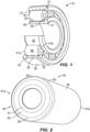
- a roller bearing or rolling element bearing 10 of the current invention includes an outer ring 20, an inner ring 30, and a set of rollers 40 arranged between and in rolling contact with the outer and inner rings 20 and 30. While the illustrated embodiment shows a cylindrical roller bearing (with cylindrical rollers), the invention can also be applied to tapered roller bearings, spherical roller bearings, and possibly, needle roller bearings.
- the outer ring 20 includes at least one radially inwardly-extending flange 21 at one end of the raceway 22 defined on the outer ring 20. In the illustrated embodiment, the outer ring 20 includes two radially inwardly-extending flanges 21. Each flange 21 includes a flange face 23 facing axially inwardly toward the raceway 22.
- the inner ring 30 includes at least one radially outwardly-extending flange 31 at one axial end of the raceway 32 defined on the inner ring 30.
- the flange 31 includes a flange face 33 facing axially inwardly toward the raceway 32.
- Each roller 40 has two end faces 41a and 41b, and an outer diameter surface 46 that engages and rolls on the raceways 22, 32.
- the end faces 41a, 41b may be made substantially symmetrical to a center radial plane (a plane perpendicular to roller axis) of the roller 40, however this need not be the case.
- each end face 41a, 41b contains a curved profile 45 defined in an axial plane through a rotational axis 47 (see Fig. 3 ) of the roller 40.
- the curved profile 45 is formed by multiple segments 51, 52, 53, 54, and 55 as, for example, shown in Figs. 2 and 3 . It is to be understood that in Fig. 3 , only the lower right corner of the roller 40 is illustrated with the profile 45 for simplicity and clarity, but that at least the upper right corner of the end face 41b would have the same profile mirrored about the axis 47. Likewise, the end face 41a could include the same profile 45 mirrored about the axial centerpoint of the roller 40.
- Each profile segment 51, 52, 53, 54 and 55 is defined by a mathematically defined curvature.
- the profile segment 51 is a portion of a straight line whose curvature radius is infinity.
- Profile segments 52 to 55 are portions of circles with curvature radii of R A2 , R B2 , R C2 , and R D2 , respectively. The centers of these curvatures are at O A2 , O B2 , O C2 , and O D2 , respectively.
- Profile segments 51 and 52 are blended at a tangent point A.
- Profile segments 52 and 53 are blended at a tangent point B.
- Profile segments 53 and 54 are blended at a tangent point C.
- Profile segments 54 and 55 are blended at a tangent point D.
- Profile segment 55 is blended with the outer diameter surface 46 of the roller 40 at point E. Unlike the other blending points (A-D), point E may or may not be a tangent point.
- the profile segment 55 is optional. In cases where the profile segment 55 is not used, profile segment 54 can be blended directly with outer diameter surface 46 at a non-tangent point.
- the locations of the profile segments 51, 52, 53, 54 and 55 of the rollers 40 are designed such that when the roller 40 is assembled and set in operation in a bearing 10 under thrust load, the contact between the roller end 41a or 41b and the mating flange face 23 and/or 33 starts at point 61 (see Figs. 4-6 ).
- a contact patch or footprint 62 is developed as contact load increases.
- the contact footprint 62 remains elliptical or circular in shape when the contact load is relatively low before reaching a load threshold of Q min .
- This ellipse or circle corresponds to profile segment 53 (BC) with the curvature radius R B2 .
- the contact footprint 62 starts to deviate from its original elliptical or circular shape. Specifically, the contact footprint 62 is truncated by segment 52 (AB) at the upper side and by segment 54 (CD) at the lower side, and assumes a non-ellipse or non-elliptical shape as represented in the area between 65 and 62. As the load further increases, the aspect ratio (length over width) of the contact footprint 62 increases, and reaches a predetermined or desirable value for optimal contact attributes, such as flange torque and/or wear rate, under a predetermined design load Q max . At load Q max , the contact footprint is represented by 65, and is non-elliptical in shape.
- the curvature center O B2 of the profile segment 53 may be offset from or located at a distance from the roller axis 47 that is within (smaller than) a distance DS 1 (see Fig. 3 ).
- the centers of curvatures for other profile segments may be offset from or located at distances from the roller axis 47 that is outside or above (greater than) DS 2 (see Fig. 3 ).
- profile segments 52 and 54 adjacent to the principal profile segment 53 need not be portions of circles. They can be, for example, a portion of exponential curves and/or logarithm curves. In yet other embodiments (such as discussed below with respect to Figs. 7-13 ), the principle profile segment 53 could be a portion of exponential curves and/or logarithm curves.
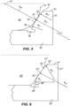
- Figs. 5 and 6 illustrate the flange faces 33, but can also represent the flange faces 23, according to the invention and described in the appended claims.
- Fig. 5 depicts a portion of a roller bearing having rollers 40' with spherical roller ends 41'.
- the profile of the roller end 41' is described by a single radius curve (R B2 ) with the center of curvature at the rotation axis 47 of the roller.
- the roller 40' is brought into contact with inner ring 30' of the bearing during operation. The contact occurs at the mating flange face 33' having at least three profile segments 34, 35, and 36.
- Each profile segment 34, 35, and 36 may be mathematically described by a radius of curvature.
- the radius of curvature (R B1 ) for the second profile segment 35 can be infinity, that is to say the second profile segment is a straight line.
- the first profile segment 34 is designed to be tangent to the second profile segment 35.
- the second profile segment 35 is tangent to the third profile segment 36.
- the first profile segment 34 is blended to the outer diameter 37 of the flange 31' at a non-tangent point.
- the third profile segment 36 is blended to the undercut 38 of the flange at another non-tangent point.
- Fig. 6 depicts a roller bearing having rollers 40" that have conical roller ends 41".
- the profile of the mating face 33" of the flange 31" is mathematically described by multi-radius curves.
- the profile has at least three segments 34", 35", and 36". Any two adjacent segments are tangent to each other.
- an elliptically-shaped or circular contact footprint initially develops.
- the elliptically-shaped or circular contact footprint corresponds to the curvature radius R B1 of the profile segment 35".
- the ellipse is truncated by profile segment 34" at the upper side and by profile segment 36" at the lower side.
- the aspect ratio of the truncated ellipse increases as the contact load increases.
- the contract footprint is non-elliptical.
- a non-elliptical contact footprint can be obtained by composite profiles at the contact location between the roller end and the mating flange face. This is to say that multi-radius profiles or multi-segment profiles can be placed either on the flange face, or on both the roller end and the flange faces, according to the invention within the scope of the claims.
- the profile segment (or segments) at the center of the contact footprint has a radius of curvature that is substantially greater than that of the segments adjacent to that center segment.
- the contract footprint is non-elliptical.
- Figs. 7-11 illustrate another roller or rolling element bearing 100 out of the scope of the claims.
- the bearing 100 includes an outer ring 120, an inner ring 130, a set of rollers 140 arranged between and in rolling contact with the outer and inner rings 120, and 130. While the illustrated embodiment shows a cylindrical roller bearing (with cylindrical rollers), the invention can also be applied to tapered roller bearings, spherical roller bearings, and, possibly, needle roller bearings.
- the outer ring 120 includes at least one radially inwardly-extending flange 121 at one end of the raceway 122 defined on the outer ring 120. In the illustrated embodiment, the outer ring 120 includes two radially inwardly-extending flanges 121. Each flange 121 includes a flange face 123 facing axially inwardly toward the raceway 122.
- the inner ring 130 includes at least one radially outwardly-extending flange 131 at one axial end of the raceway 132 defined on the inner ring 130.
- the flange 131 includes a flange face 133 facing axially inwardly toward the raceway 132.
- Each roller 140 has two end faces 141a and 141b, and an outer diameter surface 146 that engages and rolls on the raceways 122, 132.
- the end faces 141a, 141b may be made substantially symmetrical to a center radial plane (a plane perpendicular to roller axis) of the roller 140, however this need not be the case.
- each end face 141a, 141b contains a curved profile 145 defined in an axial plane that passes through the rotational axis 147 (See Fig. 9 ) of the roller 140.
- the curved profile 145 is formed by multiple segments 151, 152, 153, and 154 as for example shown in Figs. 8 and 9 . It is to be understood that in Fig. 9 , only the lower left corner of the roller 140 is illustrated with the profile 145 for simplicity and clarity, but that at least the upper left corner of the end face 141a would have the same profile 145 mirrored about the axis 147.
- Each profile segment 151, 152, 153, and 154 is defined by a mathematically described or defined curvature. Each segment 151, 152, 153, and 154 can be a straight line, a portion of a circle, or a complex curve described for example by logarithmic or exponential equations.
- the profile segment 151 is a portion of a straight line whose curvature radius is infinity.
- Profile segments 152 and 154 are portions of circles with curvature radii of R B2 and R D2 , respectively. The centers of these curvatures are at O B2 and O D2 respectively.
- Profile segments 151 and 152 are blended at tangent point A.
- Profile segments 152 and 153 are blended at a tangent point B.
- Profile segments 153 and 154 are blended at a tangent point D.
- Profile segment 153 extends from point B to point D and includes point C. As such, profile segment 153 can be broken into segment portions 153B and 153D.
- Profile segment 154 is blended with the body 146 or outer diameter of the roller 140 or a green comer of the roller at point E. Unlike blending points (A-D), point E may or may not be a tangent point.
- Profile segment 153 is a logarithmic curve or logarithmic curves described by the following equations in local x-y coordinate system whose origin is at the central contact point indicated by the reference point C or 161, with the x-axis being tangent to the roller end profile at the contact point C.
- the angle b represents the contact angle, which is also the rotation angle between the local x-y and global X G -Y G coordinate systems.
- a b and A d are constants related to deflection of the contact surfaces in y-direction under nominal design load (e.g., in some embodiments may vary from 1-100 microns, or more preferably from 10-25 microns); l b , l d , y b and y d are the distances as defined in Fig. 10 .
- l b is a distance in the local x-direction between point C and point B
- l d is a distance in the local x-direction between point C and point D
- y b is a distance in the local y-direction between point C and point B
- y d is a distance in the local y-direction between point C and point D.
- the curvature radii of the logarithmic curves are the largest. Therefore, the curvature radius at a given point decreases as the point moves along the curve away from the center of the contact point C.
- Fig. 11 shows a graphical example of a multi-segment roller end profile according to the above equations.
- equations (5a) - (5c) were incorporated.
- the locations of the profile segments 151, 152, 153, and 154 of the rollers 140 are designed such that when the roller 140 is assembled and set in operation in a bearing 100 under thrust load, the contact between roller end 141a or 141b and the mating flange face 123 and/or 133 starts at point 161.
- a footprint 162 is developed as contact load increases. The size and shape of the footprint 162 change as contact load increases. At a predetermined design load for the bearing 100, the contract footprint is non-elliptical.
- Profile segments 152 and 154 adjacent to the principal profile segment 153 need not be portions of circles. They can be, for example, be portions of exponential curves or portions of logarithmic curves. In yet other alternatives, the profile segments 152, 154 might be extensions of the logarithmic curves used for the principle profile segment 153. In yet other embodiments, there need not be additional, adjacent profile segments 152 and 154. Instead, the principle segment 153 can be the sole segment of the curved profile 145.
- Fig. 13 depicts a roller bearing with rollers 140' having conical roller ends 141'.
- the profile of the mating face 133' of the flange 131' is mathematically described by multi-segment curves.
- the profile has at least three segments 134, 135 and 136. Any two adjacent segments are tangent to each other.
- a non-elliptical contact footprint develops at a predetermined design load.
- the non-elliptical contact footprint corresponds to the logarithmic curves of the profile segment 135, which can have same curvature as the profile segment 153 described above.
- the aspect ratio of the contact footprint increases as the contact load further increases.
Landscapes
- Engineering & Computer Science (AREA)
- General Engineering & Computer Science (AREA)
- Mechanical Engineering (AREA)
- Rolling Contact Bearings (AREA)
Claims (5)
- Wälzlager (10), das Folgendes aufweist:einen inneren Laufring (30'; 30'');einen äußeren Laufring (20); undeinen Wälzkörper (40'; 40''), der zwischen und in Berührung mit dem inneren und äußeren Laufring (30'; 30'', 20) angeordnet ist;wobei das Lager einen Flansch (31'; 31'') am inneren Laufring (30'; 30") an einem axialen Ende und einen Flansch (21) am äußeren Laufring (20) an einem gegenüberliegenden axialen Ende aufweist;wobei mindestens einer der Flansche (21; 31'; 31") ein Profil mit mindestens einem Hauptsegment (35, 35''), zwischen zwei zusätzlichen Segmenten (34; 36; 34"; 36'') aufweist, wobei das Hauptsegment (35; 35'') tangential mit den zwei zusätzlichen Segmenten (34; 36; 34''; 36'') verbunden ist;wobei das Hauptsegment (35; 35") eine erste Krümmung aufweist, die sich von den jeweiligen Krümmungen der zwei zusätzlichen Segmente unterscheidet; undwobei die Krümmungen jeweils des Hauptsegments (35; 35'') und der zwei zusätzlichen Segmente (34; 36; 34''; 36'') Teile eines Kreises sind und dadurch gekennzeichnet sind, dass die erste Krümmung einen größeren Krümmungsradius (RB1) als die jeweiligen Krümmungsradien (RA1, RC1) der zwei zusätzlichen Segmente (34; 36; 34"; 36") hat.
- Wälzlager nach Anspruch 1, wobei die jeweiligen Krümmungsradien (RA1, RC1) der zwei zusätzlichen Segmente (34; 36; 34''; 36'') unterschiedlich sind.
- Wälzlager nach Anspruch 1, wobei der Wälzkörper (40') ein Wälzkörperende (41') aufweist, das mit dem profilierten Flansch eingreift, wobei das Wälzkörperende (41') kugelförmig ist.
- Wälzlager nach Anspruch 1, wobei der Wälzkörper (40") ein Wälzkörperende (41") aufweist, das mit dem profilierten Flansch eingreift, wobei das Wälzkörperende (41") konisch ist.
- Wälzlager nach Anspruch 1, wobei eine Berührungsfläche, die zwischen dem profilierten Flansch und einem Ende des Wälzkörpers (40'; 40") definiert ist, eine nichtelliptische Form aufweist, wenn das Lager unter einer vorbestimmten Auslegungslast arbeitet.
Applications Claiming Priority (4)
| Application Number | Priority Date | Filing Date | Title |
|---|---|---|---|
| US201762490392P | 2017-04-26 | 2017-04-26 | |
| US201762519464P | 2017-06-14 | 2017-06-14 | |
| PCT/US2018/028521 WO2018200324A1 (en) | 2017-04-26 | 2018-04-20 | Non-elliptical contact profile for roller bearing |
| EP18723204.6A EP3615821B1 (de) | 2017-04-26 | 2018-04-20 | Nichtelliptisches kontaktprofil für ein rollenlager |
Related Parent Applications (3)
| Application Number | Title | Priority Date | Filing Date |
|---|---|---|---|
| PCT/US2018/028521 Previously-Filed-Application WO2018200324A1 (en) | 2017-04-26 | 2018-04-20 | Non-elliptical contact profile for roller bearing |
| EP18723204.6A Division EP3615821B1 (de) | 2017-04-26 | 2018-04-20 | Nichtelliptisches kontaktprofil für ein rollenlager |
| EP18723204.6A Division-Into EP3615821B1 (de) | 2017-04-26 | 2018-04-20 | Nichtelliptisches kontaktprofil für ein rollenlager |
Publications (3)
| Publication Number | Publication Date |
|---|---|
| EP4151872A1 EP4151872A1 (de) | 2023-03-22 |
| EP4151872C0 EP4151872C0 (de) | 2024-12-18 |
| EP4151872B1 true EP4151872B1 (de) | 2024-12-18 |
Family
ID=62117050
Family Applications (3)
| Application Number | Title | Priority Date | Filing Date |
|---|---|---|---|
| EP22175637.2A Active EP4151873B1 (de) | 2017-04-26 | 2018-04-20 | Nichtelliptisches kontaktprofil für ein zylinderrollenlager |
| EP18723204.6A Active EP3615821B1 (de) | 2017-04-26 | 2018-04-20 | Nichtelliptisches kontaktprofil für ein rollenlager |
| EP22175634.9A Active EP4151872B1 (de) | 2017-04-26 | 2018-04-20 | Nichtelliptisches kontaktprofil für ein zylinderrollenlager |
Family Applications Before (2)
| Application Number | Title | Priority Date | Filing Date |
|---|---|---|---|
| EP22175637.2A Active EP4151873B1 (de) | 2017-04-26 | 2018-04-20 | Nichtelliptisches kontaktprofil für ein zylinderrollenlager |
| EP18723204.6A Active EP3615821B1 (de) | 2017-04-26 | 2018-04-20 | Nichtelliptisches kontaktprofil für ein rollenlager |
Country Status (6)
| Country | Link |
|---|---|
| US (2) | US11053978B2 (de) |
| EP (3) | EP4151873B1 (de) |
| CN (3) | CN113864327B (de) |
| DK (1) | DK3615821T3 (de) |
| ES (3) | ES3000418T3 (de) |
| WO (1) | WO2018200324A1 (de) |
Families Citing this family (2)
| Publication number | Priority date | Publication date | Assignee | Title |
|---|---|---|---|---|
| CN111734742A (zh) * | 2020-07-20 | 2020-10-02 | 常州克劳诺斯特种轴承制造有限公司 | 曲端面圆柱滚子、圆柱滚子轴承 |
| DE102020211036B4 (de) * | 2020-09-02 | 2022-04-14 | Aktiebolaget Skf | Anordnung mit einem Schleifwerkzeug und einer Rolle für ein Rollenlager sowie Verfahren zum Herstellen einer Rolle für ein Rollenlager |
Citations (1)
| Publication number | Priority date | Publication date | Assignee | Title |
|---|---|---|---|---|
| EP2309143A1 (de) * | 2008-07-01 | 2011-04-13 | NTN Corporation | Lagerrolle, lager und lagerrollenbearbeitungsverfahren |
Family Cites Families (18)
| Publication number | Priority date | Publication date | Assignee | Title |
|---|---|---|---|---|
| US3740108A (en) * | 1971-11-15 | 1973-06-19 | Skf Ind Trading & Dev | Cylindrical roller bearing |
| US5071265A (en) * | 1991-01-09 | 1991-12-10 | Zrb Bearing, Inc. | Hollow roller bearing assembly for both radial and axial loads |
| JP2000065066A (ja) | 1998-08-19 | 2000-03-03 | Nippon Seiko Kk | 円筒ころ軸受 |
| JP2003021145A (ja) * | 2001-07-05 | 2003-01-24 | Nsk Ltd | ころ軸受 |
| CN100375853C (zh) * | 2001-11-06 | 2008-03-19 | 日本精工株式会社 | 径向滚子轴承 |
| JP2004353744A (ja) | 2003-05-28 | 2004-12-16 | Nsk Ltd | ころ軸受 |
| WO2004111477A1 (ja) * | 2003-06-12 | 2004-12-23 | Nsk Ltd. | 円筒ころ軸受 |
| DE102005061103A1 (de) | 2005-12-21 | 2007-07-05 | Schaeffler Kg | Wälzlager mit verbesserter Bordgeometrie |
| DE102005061102A1 (de) | 2005-12-21 | 2007-07-05 | Schaeffler Kg | Wälzlager |
| DE102010062481B3 (de) * | 2010-12-06 | 2011-12-15 | Aktiebolaget Skf | Geometriekonzept für einen Rolle-Bord-Kontakt bei Rollenlagern |
| DE102011076328B4 (de) * | 2011-05-24 | 2013-11-07 | Aktiebolaget Skf | Geometriekonzept für einen Bord eines Rollenlagers |
| JP2013117249A (ja) * | 2011-12-02 | 2013-06-13 | Ntn Corp | ころ軸受 |
| CN203477076U (zh) * | 2013-09-27 | 2014-03-12 | 日本精工株式会社 | 圆锥滚子轴承 |
| DE102013225859B4 (de) * | 2013-12-13 | 2019-10-10 | Aktiebolaget Skf | Laufbahnelement und Rollenlager mit dem Laufbahnelement |
| JP6256023B2 (ja) * | 2014-01-16 | 2018-01-10 | 株式会社ジェイテクト | 円すいころ軸受及び動力伝達装置 |
| JP6323136B2 (ja) * | 2014-04-16 | 2018-05-16 | 株式会社ジェイテクト | ころ軸受用軌道輪、ころ軸受及び動力伝達装置 |
| JP2017044281A (ja) * | 2015-08-27 | 2017-03-02 | Ntn株式会社 | 保持器及び円すいころ軸受 |
| DK3411600T3 (da) * | 2016-07-19 | 2020-05-11 | Timken Co | Rulleleje med forøget rulleende- og flangekontakt |
-
2018
- 2018-04-20 ES ES22175634T patent/ES3000418T3/es active Active
- 2018-04-20 US US16/607,172 patent/US11053978B2/en active Active
- 2018-04-20 DK DK18723204.6T patent/DK3615821T3/da active
- 2018-04-20 CN CN202111354184.8A patent/CN113864327B/zh active Active
- 2018-04-20 EP EP22175637.2A patent/EP4151873B1/de active Active
- 2018-04-20 ES ES18723204T patent/ES2925254T3/es active Active
- 2018-04-20 EP EP18723204.6A patent/EP3615821B1/de active Active
- 2018-04-20 CN CN201880042481.9A patent/CN110869628B/zh active Active
- 2018-04-20 EP EP22175634.9A patent/EP4151872B1/de active Active
- 2018-04-20 CN CN202411199106.9A patent/CN119021972A/zh active Pending
- 2018-04-20 WO PCT/US2018/028521 patent/WO2018200324A1/en not_active Ceased
- 2018-04-20 ES ES22175637T patent/ES2999009T3/es active Active
-
2021
- 2021-05-28 US US17/334,071 patent/US11624402B2/en active Active
Patent Citations (1)
| Publication number | Priority date | Publication date | Assignee | Title |
|---|---|---|---|---|
| EP2309143A1 (de) * | 2008-07-01 | 2011-04-13 | NTN Corporation | Lagerrolle, lager und lagerrollenbearbeitungsverfahren |
Also Published As
| Publication number | Publication date |
|---|---|
| US11624402B2 (en) | 2023-04-11 |
| EP4151873B1 (de) | 2024-12-18 |
| US20200386272A1 (en) | 2020-12-10 |
| CN119021972A (zh) | 2024-11-26 |
| DK3615821T3 (en) | 2022-10-03 |
| CN110869628A (zh) | 2020-03-06 |
| CN113864327B (zh) | 2025-05-16 |
| US20210285493A1 (en) | 2021-09-16 |
| EP4151872C0 (de) | 2024-12-18 |
| ES3000418T3 (en) | 2025-02-28 |
| CN110869628B (zh) | 2021-10-08 |
| ES2999009T3 (en) | 2025-02-24 |
| EP3615821A1 (de) | 2020-03-04 |
| EP4151873A1 (de) | 2023-03-22 |
| WO2018200324A1 (en) | 2018-11-01 |
| EP4151873C0 (de) | 2024-12-18 |
| ES2925254T3 (es) | 2022-10-14 |
| US11053978B2 (en) | 2021-07-06 |
| EP3615821B1 (de) | 2022-07-27 |
| CN113864327A (zh) | 2021-12-31 |
| EP4151872A1 (de) | 2023-03-22 |
Similar Documents
| Publication | Publication Date | Title |
|---|---|---|
| CN103717925B (zh) | 滚子轴承的挡边的几何设计 | |
| JPH04331813A (ja) | 円すいころ軸受 | |
| US6616339B2 (en) | Roller bearing | |
| US8480308B2 (en) | Tapered roller bearing, tapered roller bearing apparatus, and automotive pinion shaft supporting apparatus utilizing same tapered roller bearing apparatus | |
| US11624402B2 (en) | Non-elliptical contact profile for roller bearing | |
| JP2009520936A (ja) | 転がり軸受 | |
| DE102013215890B3 (de) | Lagerstelle mit einem einreihigen Polygonlager | |
| CN101365889B (zh) | 具有改进的凸边几何形状的滚动轴承 | |
| US5902022A (en) | Controlled contact stress roller bearing | |
| EP3396184B1 (de) | Kreuzrollenlager | |
| US20150198206A1 (en) | Torque-transmitting joint and joint components, methods of manufacturing, and methods of inspection | |
| EP3411600B1 (de) | Wälzlager mit verbessertem kontakt des wälzkörperends und des wälzlagerflansches | |
| EP2981724B1 (de) | Kugellager und verfahren zur herstellung davon | |
| DE102010011462A1 (de) | Kegelrollenlager mit profilierter Laufbahn | |
| US20180163782A1 (en) | Bearing cage, rolling element bearing and method | |
| EP3022454B1 (de) | Rollenlager mit einer gewölbten kontaktlinie | |
| US20130202240A1 (en) | Turning bearing with rollers between outer ring and inner ring | |
| JP3900843B2 (ja) | スラストころ軸受の保持器 | |
| DE102015223125B4 (de) | Lagerstelle mit zwei Polygonlagern und zweistufiger Steifigkeitskennlinie | |
| EP3215751B1 (de) | Wälzlageranordnung | |
| CN116615612B (zh) | 调心滚子轴承 | |
| WO2023283085A1 (en) | High-capacity cylindrical roller bearing and cage | |
| DE102011088692A1 (de) | Zylinderrollenlager sowie Verfahren zur Auslegung des Zylinderrollenlagers |
Legal Events
| Date | Code | Title | Description |
|---|---|---|---|
| PUAI | Public reference made under article 153(3) epc to a published international application that has entered the european phase |
Free format text: ORIGINAL CODE: 0009012 |
|
| STAA | Information on the status of an ep patent application or granted ep patent |
Free format text: STATUS: THE APPLICATION HAS BEEN PUBLISHED |
|
| AC | Divisional application: reference to earlier application |
Ref document number: 3615821 Country of ref document: EP Kind code of ref document: P |
|
| AK | Designated contracting states |
Kind code of ref document: A1 Designated state(s): AL AT BE BG CH CY CZ DE DK EE ES FI FR GB GR HR HU IE IS IT LI LT LU LV MC MK MT NL NO PL PT RO RS SE SI SK SM TR |
|
| STAA | Information on the status of an ep patent application or granted ep patent |
Free format text: STATUS: REQUEST FOR EXAMINATION WAS MADE |
|
| 17P | Request for examination filed |
Effective date: 20230807 |
|
| RBV | Designated contracting states (corrected) |
Designated state(s): AL AT BE BG CH CY CZ DE DK EE ES FI FR GB GR HR HU IE IS IT LI LT LU LV MC MK MT NL NO PL PT RO RS SE SI SK SM TR |
|
| STAA | Information on the status of an ep patent application or granted ep patent |
Free format text: STATUS: EXAMINATION IS IN PROGRESS |
|
| 17Q | First examination report despatched |
Effective date: 20240313 |
|
| RIC1 | Information provided on ipc code assigned before grant |
Ipc: F16C 33/64 20060101ALN20240605BHEP Ipc: F16C 33/58 20060101ALI20240605BHEP Ipc: F16C 33/36 20060101AFI20240605BHEP |
|
| RIC1 | Information provided on ipc code assigned before grant |
Ipc: F16C 33/64 20060101ALN20240611BHEP Ipc: F16C 33/58 20060101ALI20240611BHEP Ipc: F16C 33/36 20060101AFI20240611BHEP |
|
| GRAP | Despatch of communication of intention to grant a patent |
Free format text: ORIGINAL CODE: EPIDOSNIGR1 |
|
| STAA | Information on the status of an ep patent application or granted ep patent |
Free format text: STATUS: GRANT OF PATENT IS INTENDED |
|
| RIC1 | Information provided on ipc code assigned before grant |
Ipc: F16C 33/64 20060101ALN20240703BHEP Ipc: F16C 33/58 20060101ALI20240703BHEP Ipc: F16C 33/36 20060101AFI20240703BHEP |
|
| INTG | Intention to grant announced |
Effective date: 20240723 |
|
| GRAS | Grant fee paid |
Free format text: ORIGINAL CODE: EPIDOSNIGR3 |
|
| GRAA | (expected) grant |
Free format text: ORIGINAL CODE: 0009210 |
|
| STAA | Information on the status of an ep patent application or granted ep patent |
Free format text: STATUS: THE PATENT HAS BEEN GRANTED |
|
| AC | Divisional application: reference to earlier application |
Ref document number: 3615821 Country of ref document: EP Kind code of ref document: P |
|
| AK | Designated contracting states |
Kind code of ref document: B1 Designated state(s): AL AT BE BG CH CY CZ DE DK EE ES FI FR GB GR HR HU IE IS IT LI LT LU LV MC MK MT NL NO PL PT RO RS SE SI SK SM TR |
|
| REG | Reference to a national code |
Ref country code: CH Ref legal event code: EP |
|
| REG | Reference to a national code |
Ref country code: DE Ref legal event code: R096 Ref document number: 602018077858 Country of ref document: DE |
|
| REG | Reference to a national code |
Ref country code: IE Ref legal event code: FG4D |
|
| U01 | Request for unitary effect filed |
Effective date: 20241218 |
|
| U07 | Unitary effect registered |
Designated state(s): AT BE BG DE DK EE FI FR IT LT LU LV MT NL PT RO SE SI Effective date: 20250110 |
|
| REG | Reference to a national code |
Ref country code: ES Ref legal event code: FG2A Ref document number: 3000418 Country of ref document: ES Kind code of ref document: T3 Effective date: 20250228 |
|
| PG25 | Lapsed in a contracting state [announced via postgrant information from national office to epo] |
Ref country code: HR Free format text: LAPSE BECAUSE OF FAILURE TO SUBMIT A TRANSLATION OF THE DESCRIPTION OR TO PAY THE FEE WITHIN THE PRESCRIBED TIME-LIMIT Effective date: 20241218 |
|
| PG25 | Lapsed in a contracting state [announced via postgrant information from national office to epo] |
Ref country code: NO Free format text: LAPSE BECAUSE OF FAILURE TO SUBMIT A TRANSLATION OF THE DESCRIPTION OR TO PAY THE FEE WITHIN THE PRESCRIBED TIME-LIMIT Effective date: 20250318 |
|
| PG25 | Lapsed in a contracting state [announced via postgrant information from national office to epo] |
Ref country code: GR Free format text: LAPSE BECAUSE OF FAILURE TO SUBMIT A TRANSLATION OF THE DESCRIPTION OR TO PAY THE FEE WITHIN THE PRESCRIBED TIME-LIMIT Effective date: 20250319 |
|
| PG25 | Lapsed in a contracting state [announced via postgrant information from national office to epo] |
Ref country code: RS Free format text: LAPSE BECAUSE OF FAILURE TO SUBMIT A TRANSLATION OF THE DESCRIPTION OR TO PAY THE FEE WITHIN THE PRESCRIBED TIME-LIMIT Effective date: 20250318 |
|
| U20 | Renewal fee for the european patent with unitary effect paid |
Year of fee payment: 8 Effective date: 20250425 |
|
| PG25 | Lapsed in a contracting state [announced via postgrant information from national office to epo] |
Ref country code: SM Free format text: LAPSE BECAUSE OF FAILURE TO SUBMIT A TRANSLATION OF THE DESCRIPTION OR TO PAY THE FEE WITHIN THE PRESCRIBED TIME-LIMIT Effective date: 20241218 |
|
| PG25 | Lapsed in a contracting state [announced via postgrant information from national office to epo] |
Ref country code: PL Free format text: LAPSE BECAUSE OF FAILURE TO SUBMIT A TRANSLATION OF THE DESCRIPTION OR TO PAY THE FEE WITHIN THE PRESCRIBED TIME-LIMIT Effective date: 20241218 |
|
| PGFP | Annual fee paid to national office [announced via postgrant information from national office to epo] |
Ref country code: GB Payment date: 20250423 Year of fee payment: 8 Ref country code: ES Payment date: 20250530 Year of fee payment: 8 |
|
| PG25 | Lapsed in a contracting state [announced via postgrant information from national office to epo] |
Ref country code: IS Free format text: LAPSE BECAUSE OF FAILURE TO SUBMIT A TRANSLATION OF THE DESCRIPTION OR TO PAY THE FEE WITHIN THE PRESCRIBED TIME-LIMIT Effective date: 20250418 |
|
| PG25 | Lapsed in a contracting state [announced via postgrant information from national office to epo] |
Ref country code: SK Free format text: LAPSE BECAUSE OF FAILURE TO SUBMIT A TRANSLATION OF THE DESCRIPTION OR TO PAY THE FEE WITHIN THE PRESCRIBED TIME-LIMIT Effective date: 20241218 |
|
| PG25 | Lapsed in a contracting state [announced via postgrant information from national office to epo] |
Ref country code: CZ Free format text: LAPSE BECAUSE OF FAILURE TO SUBMIT A TRANSLATION OF THE DESCRIPTION OR TO PAY THE FEE WITHIN THE PRESCRIBED TIME-LIMIT Effective date: 20241218 |
|
| PLBE | No opposition filed within time limit |
Free format text: ORIGINAL CODE: 0009261 |
|
| STAA | Information on the status of an ep patent application or granted ep patent |
Free format text: STATUS: NO OPPOSITION FILED WITHIN TIME LIMIT |
|
| REG | Reference to a national code |
Ref country code: CH Ref legal event code: L10 Free format text: ST27 STATUS EVENT CODE: U-0-0-L10-L00 (AS PROVIDED BY THE NATIONAL OFFICE) Effective date: 20251029 |
|
| REG | Reference to a national code |
Ref country code: CH Ref legal event code: H13 Free format text: ST27 STATUS EVENT CODE: U-0-0-H10-H13 (AS PROVIDED BY THE NATIONAL OFFICE) Effective date: 20251125 |
|
| 26N | No opposition filed |
Effective date: 20250919 |
|
| PG25 | Lapsed in a contracting state [announced via postgrant information from national office to epo] |
Ref country code: MC Free format text: LAPSE BECAUSE OF FAILURE TO SUBMIT A TRANSLATION OF THE DESCRIPTION OR TO PAY THE FEE WITHIN THE PRESCRIBED TIME-LIMIT Effective date: 20241218 |
|
| PG25 | Lapsed in a contracting state [announced via postgrant information from national office to epo] |
Ref country code: CH Free format text: LAPSE BECAUSE OF NON-PAYMENT OF DUE FEES Effective date: 20250430 |
|
| PG25 | Lapsed in a contracting state [announced via postgrant information from national office to epo] |
Ref country code: IE Free format text: LAPSE BECAUSE OF NON-PAYMENT OF DUE FEES Effective date: 20250420 |