EP4151821A1 - Griffanordung für eine kraftfahrzeugtür - Google Patents
Griffanordung für eine kraftfahrzeugtür Download PDFInfo
- Publication number
- EP4151821A1 EP4151821A1 EP22189779.6A EP22189779A EP4151821A1 EP 4151821 A1 EP4151821 A1 EP 4151821A1 EP 22189779 A EP22189779 A EP 22189779A EP 4151821 A1 EP4151821 A1 EP 4151821A1
- Authority
- EP
- European Patent Office
- Prior art keywords
- handle
- end section
- support arm
- vehicle door
- handle body
- Prior art date
- Legal status (The legal status is an assumption and is not a legal conclusion. Google has not performed a legal analysis and makes no representation as to the accuracy of the status listed.)
- Granted
Links
Images




Classifications
-
- E—FIXED CONSTRUCTIONS
- E05—LOCKS; KEYS; WINDOW OR DOOR FITTINGS; SAFES
- E05B—LOCKS; ACCESSORIES THEREFOR; HANDCUFFS
- E05B85/00—Details of vehicle locks not provided for in groups E05B77/00 - E05B83/00
- E05B85/10—Handles
- E05B85/14—Handles pivoted about an axis parallel to the wing
- E05B85/16—Handles pivoted about an axis parallel to the wing a longitudinal grip part being pivoted at one end about an axis perpendicular to the longitudinal axis of the grip part
-
- E—FIXED CONSTRUCTIONS
- E05—LOCKS; KEYS; WINDOW OR DOOR FITTINGS; SAFES
- E05B—LOCKS; ACCESSORIES THEREFOR; HANDCUFFS
- E05B79/00—Mounting or connecting vehicle locks or parts thereof
- E05B79/02—Mounting of vehicle locks or parts thereof
- E05B79/06—Mounting of handles, e.g. to the wing or to the lock
Definitions
- the present invention is directed to the field of vehicle door handles, specifically to a handle assembly for a motor vehicle door.
- Known automotive door handle assemblies include a handle body for user pull operation and a bracket on the inside of the door panel for locating the handle body on the door.
- the handle body is connected to the carrier on the inside of the door by two brackets at its two end sections.
- the two support arms are inserted into the support from the outside through the recesses in the door body.
- the handle body can assume two positions, namely the rest position and the open position. During the opening movement, the handle body can pivot from the rest position into the open position.
- a support arm on a handle body end section is at least partially pulled outwards from the inside of the door through the recess in the door body, while the opposite support arm remains on the support and pivots about an axis formed in the support or about a point formed in the support.
- the handle assembly for a motor vehicle door comprises a carrier, which is arranged on the inside of the door panel, a handle body, which is arranged on the outside of the door, the handle body having a first end portion and a second end portion, the second end portion from the outside the vehicle door is pivotally mounted through a recess on the carrier, wherein the second End portion has a support arm with a curvature.
- An arc-shaped guideway is arranged in the carrier, the support arm of the second end section being slidable in the carrier so as to be pivotable about the center point of the circular arc.
- the arc of a circle is part of a circle.
- the present invention improves the state of the art by manually defining an artificially generated virtual pivoting center point by means of a circular arc-shaped guideway, and by sliding the support arm of the second handle body end section in the guideway when the handle body is pivoted in the carrier, so that the movable design of the handle body of the door body is optimized.
- the arcuate track in the carrier forms the actual trajectory of movement of the support arm of the second end portion of the handle body when it slides pivotally in the carrier. This means that the support arm of the handle body second end portion in fact slides in the circular guideway mentioned above.
- the arcuate track is structurally defined and uniquely defined by the carrier and/or the parts in the carrier together with the support arm of the second handle body end portion. Accordingly, the center point of the circular arc-shaped guideway is clearly defined.
- the circular arc-shaped guide path can be defined together by the contact surface and/or the contact point and/or the contact points between the carrier and/or the parts in the carrier and the support arm of the second end section of the handle body and, moreover, three points are theoretically required to form a circle center point of a circle to define, the contact surface and/or the contact point and/or the contact points can only be partially distributed and defined on the actual circular arc-shaped movement curve in the carrier where the carrier arm of the second handle body end section pivots. Therefore, the guideway in the form of a circular arc can in fact be partially virtual, namely invisible on the components. However, the guideway is clearly defined.
- the fact that the support arm of the second handle body end section can pivot around the center point of the arcuate guideway means that the center point of the arcuate guideway defines the pivot point of the entire handle body when moving from the rest position to the open position.
- the contact surface and/or the contact point and/or the contact points between the carrier and/or the parts in the carrier and the support arm of the second handle body end section can be designed in such a way that the angle that the support arm of the second handle body end section pivotally slidably occupies in the arcuate guide track can, at least equal to or greater than the angle that the handle body is pivotally occupied from the rest position to the maximum open position.
- the center point of the arc-shaped guideway is located in the door body or on the side facing away from the vehicle outside the door body. That is, when the handle body is pulled, the pivoting center of the pivoting movement is in the door body or on the non-vehicle side outside of the door body. Based on the principle that any point on a circle with a fixed semi-diameter is always the same distance from the center of the circle (the semi-diameter), the handle body or the support arm will, when pivoting, touch the edge of the recess in the body that is on the side of the movement of the Support arm is directed bypass to successfully avoid a collision with the door body.
- the carrier has a slide member, the slide member being in contact with the concave side of the curvature of the bracket of the second handle body end portion, the bracket of the second handle body end portion lying on the convex side of the bracket.
- the support arm of the second handle body end section moves in a groove formed between the slideway element and the carrier.
- the groove corresponds at least in part to the arcuate guide track.
- the slideway element can be a separate component in the carrier.
- a flexible design of the arcuate guide track can be achieved with a separate component in order to adjust the center point of the circle.
- the slideway element can be designed to be integrated in one piece in the carrier. In an injection-moulded carrier, the slideway element can be formed very easily directly in the tool.
- the point of contact between the bracket of the second end portion of the grip body and the bracket can be formed so that the grip body is limited in the vehicle X-axis. This means that movement in the vehicle X-axis is prevented.
- the advantage is that the pivoting movement of the grip body becomes more stable and the center point of the arc-shaped guideway is fixed.
- the slideway element and the support arm of the second handle body end section can come into contact through a contact surface and/or a contact point, while the support arm of the second handle body end section can lie on the convex side through a contact surface and/or a contact point on the carrier, so that a single circular arc-shaped movement curve is defined in the carrier, as the support arm can be pivoted sliding.
- the support arm of the second end section of the grip body comes into contact with the slideway element on the concave side or with the carrier on the convex side at least through a contact surface
- the support arm of the second end section of the grip body comes into contact with the carrier or the slideway element on the opposite side at least through a contact surface or a contact point in contact.
- the support arm of the second handle body end section comes into contact with the slideway element on the concave side or with the carrier on the convex side at least through two contact points
- the support arm of the second handle body end section then comes into contact with the carrier on the opposite side or in contact with the slideway element at least through a contact surface or a contact point.
- the contact surface, the contact point or the contact points between the support arm of the second handle body end section and the slideway element or the carrier can be realized by a contact surface, a contact point or contact points.
- the support point or the support points can be arranged on the support arm of the second handle body end section or on the slideway element and on the support arm of the second handle body end section or on the carrier.
- the bearing surface can be arranged on the support arm of the second end section of the grip body or on the slideway element and can be arranged on the support arm of the second end section of the grip body or on the carrier. Alternatively, the bearing surface can be arranged simultaneously on the support arm of the second handle body end section, on the slideway element and on the carrier.
- a handle assembly for a motor vehicle door 1 comprises a carrier 2 and a handle body 3.
- the carrier 2 is arranged on the inside of the door and the handle body 3 is arranged on the outside of the door.
- the handle body 3 has a first end portion 3a and a second end portion 3b.
- the first end portion 3a and the second end portion 3b are both arranged on the carrier.
- the second end portion 3b has a bracket 4 with a bend.
- the side 5a of the slideway member 5 directed to the concave side of the curvature of the bracket 4 of the second end portion of the handle body is arc-shaped as viewed from the vehicle Z-axis.
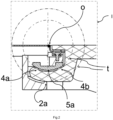
- the second end portion 3b of the handle body two support points 4a and 4b, which are as contact points between the support arm 4 of the second handle body end portion 3b on the arcuate side 5a of the slide element.
- the support arm 4 of the second handle body end section 3b lies on the convex side of the curvature on the support 2.
- the support has a support point 2a at the contact point. Therefore, the support arm 4 of the second handle body end portion 3b in the bracket 2 in the space between the bracket 2 and the slide member 5, particularly in the space between the contact points 4a, 4b and 2a, along the circular-arc-shaped side of the slide member 5 pivot slidably.
- the center point o of the circular arc-shaped side of the slideway element 5 is namely the pivoting center point of the support arm 4 of the second handle body end section 3a or of the entire handle body 3.
- the curve in space that the support arm 4 of the second handle body end section 3b has occupied in the carrier 2 during the sliding movement, is the circular-arc guideway t (in order to clearly indicate the relationship between the guideway and the center of the circle, the whole circle where the guideway t is located is marked.).
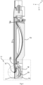
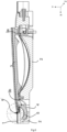
- FIG. 1 shows the handle body 3 in the rest position and 3 shows the handle body 3 in the open position.
- the handle body 3 can be pulled out manually by the user about the pivot point o or driven out by the motor. It can be seen that the handle body 3 when pivoting about the pivot center in 1 and 3 does not tend to move inwards of the beam 2 and to the left at the same time, because any point on a circle with a fixed semidiameter is always the same distance from the center of the circle. Therefore, the handle body 3 will not collide with the door body 4 adjacent to its left.
- FIGs 4-6 another embodiment of the present invention is displayed.
- the slideway element 5' is not additionally equipped, but is integrally formed on the carrier 2.
- the slideway element has a circular-arc-shaped side 5a'.
- the second end section 3b of the handle body has two support points 4a and 4b, which are contact points between the support arm 4 of the second handle body end section 3b on the arcuate side 5a' of the slideway element.
- the support arm 4 of the second handle body end section 3b lies on the convex side of the curve on the support 2.
- the support has a bearing surface 2b at the contact point.
- the bearing surface 2b lies on the convex side of the curvature of the support arm 4 of the second handle body end portion 3b.
- the support arm 4 of the second handle body end section 3b can pivot in the carrier 2 in the space between the contact points 4a, 4b and the contact surface 2b along the arcuate side 5a' of the slide element 5' in a sliding manner.
- the circle center o 'of the circular arc-shaped side of the slideway element 5 is namely the pivoting center of the support arm 4 of the second Griffismeendabitess 3a or the entire handle body 3.
- the curve in space, which the support arm 4 of the second Griffismeendabites 3b has occupied in the beam 2 during the sliding movement is the circular-arc guideway t' (in order to clearly show the relationship between the guideway and the center of the circle, the whole circle is marked where the guideway t' is located.).
- FIG.4 shows the handle body 3 in the rest position and 6 shows the handle body 3 in the open position.
- the grip body 3 can be pulled out manually by the user about the pivot point o' or driven out by the motor. It can be seen that the handle body 3 when pivoting about the pivot center in 4 and 6 does not tend to move inwards of the beam 2 and to the left at the same time, because any point on a circle with a fixed semidiameter is always the same distance from the center of the circle. Therefore, the handle body 3 will not collide with the door body 4 adjacent to it on the left.
- the contact methods between the support arm 4 of the second handle body end section 3b and the slideway element 5, 5' or the carrier 2 are limited to the contact methods shown in the figures.
- the use of the contact surface, the contact point or the contact points can be freely selected as long as this contact type/contact type combination clearly defines the center of the circle of the movement curve of the support arm 4 of the second handle body end section 3b.
- FIG. 1-3 in Figures 4-6 are not limited to flush door handle assemblies which are flush with the door body in the inoperative position.
- the examples in Figures 1-3 and Figures 4-6 can also be used as an alternative for the handle body, which protrudes from the door body in the rest position.
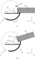
- FIGS. 7-10 illustrate the basic sketches of the door handle assembly according to the invention for a motor vehicle door.
- any components of the handle assembly are indicated only by simple shapes.
- the handle body 3 has the support arm 4 on one end section.
- the concrete shape of the bracket 4 is not limited to a circular arc as in the sketch.
- the support arm can slide in the arcuate path t' with the center of the circle o " pivot.
- the arcuate t" is in the carrier of the handle assembly (in Figures 7-10 not displayed).
- the center of the circle o " is on the side facing away from the vehicle outside the door body.
- the distance from the point on the handle body 3 which is closest to the door body edge to the center of the circle is the semi-diameter r.
- the present invention is directed to the field of vehicle door handles, specifically to a handle assembly for a motor vehicle door.
- Handle assembly for a motor vehicle door comprising a carrier which is arranged on the inside of the door panel, a handle body which is arranged on the outside of the door, the handle body having a first end section and a second end section, the second end section extending from the outside of the
- the vehicle door is pivotably mounted on the support through a recess, the second end section having a support arm with a curvature, characterized in that a circular arc-shaped guide track is arranged in the support, the support arm of the second end section being designed to slide in the support so as to be pivotable about the center point of the circular arc is.
- the present invention enables the door handle assembly not to interfere with the door body when swinging, and the design can be made more flexible
Landscapes
- Lock And Its Accessories (AREA)
Abstract
Description
- Die vorliegende Erfindung ist auf den Bereich des Fahrzeugtürgriffs, konkret auf eine Griffanordnung für eine Kraftfahrzeugtür gerichtet.
- Bekannte Kraftfahrzeugtürgriffanordnungen weisen einen Griffkörper für eine Ziehbetätigung durch den Nutzer und einen Träger an der Innenseite des Türbleches zum Anordnung des Griffkörpers an der Tür auf. Der Griffkörper ist an der Türinnenseite durch zwei Tragarme an seinen beiden Endabschnitten mit dem Träger verbunden. Die beiden Tragarme sind durch die Ausnehmungen der Türkarosserie von der Außenseite in den Träger eingesteckt. Im Vergleich zur Fahrzeugtür kann der Griffkörper zwei Stellungen einnehmen, nämlich die Ruhestellung und die Öffnungsstellung. Der Griffkörper kann bei der Öffnungsbewegung von der Ruhestellung in die Öffnungsstellung schwenken. In der Öffnungsstellung ist ein Tragarm an einem Griffkörperendabschnitt zumindest teilweise von Türinnenseite durch die Ausnehmung der Türkarosserie nach Außen gezogen, während der gegenüberliegende Tragarm am Träger bleibt und sich um eine im Träger gebildete Achse oder um einen im Träger gebildeten Punkt schwenkt. Wenn sich die Türgriffanordnung schwenkt, verkleinert sich die Lücke zwischen dem Griffkörper bzw. dem Tragarm und dem Rand der Ausnehmung der Türkarosserie bis zur Kollision, sodass bei Auslegung der Ausnehmung der Türkarosserie die Bewegungskurve des Griffgriffs berücksichtigt werden muss, um die Umgehungsmaßnahme zu ergreifen.
- Es ist Aufgabe der vorliegenden Erfindung, auf Basis des Stands der Technik die Türgriffanordnung zu verbessern, sodass beim Schwenken die Türgriffordnung nicht mit der Türkarosserie kollidiert und die Ausgestaltung flexibler gestaltet werden kann.
- Das Ziel der Erfindung wird durch folgende technische Lösung erreicht:
Die Griffanordnung für eine Kraftfahrzeugtür, umfasst einen Träger, der an der Innenseite des Türbleches angeordnet ist, einen Griffkörper, der an der Außenseite der Tür angeordnet ist, wobei der Griffkörper einen ersten Endabschnitt und einen zweiten Endabschnitt aufweist, wobei der zweite Endabschnitt von der Außenseite der Fahrzeugtür durch einer Ausnehmung schwenkbar am Träger gelagert ist, wobei der zweite Endabschnitt einen Tragarm mit einer Krümmung aufweist. Eine kreisbogenförmige Führungsbahn ist im Träger angeordnet, wobei der Tragarm des zweiten Endabschnitts sich um den Kreismittelpunkt des Kreisbogens schwenkbar im Träger gleitend ausgebildet ist. Erfindungsgemäß ist der Kreisbogen ein Teil eines Kreises. Die vorliegende Erfindung verbessert den Stand der Technik, indem durch eine kreisbogenförmige Führungsbahn ein künstlich erzeugter virtueller Schwenkzentralpunkt manuell definiert wird, und der Tragarm des zweiten Griffkörperendabschnitts in der Führungsbahn beim Schwenken des Griffkörpers im Träger gleitend geführt wird, so dass die bewegliche Ausgestaltung des Griffkörpers an der Türkarosserie optimiert wird. - Die kreisbogenförmige Führungsbahn im Träger bildet die tatsächliche Bewegungskurve des Tragarms des zweiten Griffkörperendabschnitts, wenn dieser im Träger schwenkbar gleitet. Das heißt, dass der Tragarm des zweiten Griffkörperendabschnitts in der Tat in der oben genannten kreisförmigen Führungsbahn gleitet. Die kreisbogenförmige Führungsbahn ist strukturell durch den Träger und/oder die Teile im Träger mit dem Tragarm des zweiten Griffkörperendabschnitts zusammen definiert und eindeutig festgelegt. Dementsprechend ist der Kreismittelpunkt der kreisbogenförmigen Führungsbahn eindeutig festgelegt. Weil die kreisbogenförmige Führungsbahn durch die Kontaktfläche und/oder den Kontaktpunkt und/oder die Kontaktpunkte zwischen dem Träger und/oder den Teilen im Träger und dem Tragarm des zweiten Griffkörperendabschnitts zusammen definiert werden kann und außerdem theoretisch drei Punkte benötigt werden, um einen Kreismittelpunktpunkt eines Kreises zu definieren, können die Kontaktfläche und/oder der Kontaktpunkt und/oder die Kontaktpunkte nur partiell an der tatsächlichen kreisbogenförmigen Bewegungskurve im Träger verteilt und definiert werden, wo der Tragarm des zweiten Griffkörperendabschnitts sich schwenkt. Daher kann die kreisbogenförmige Führungsbahn zum Teil in der Tat virtuell sein, nämlich unsichtbar an den Bauteilen. Jedoch ist die Führungsbahn eindeutig festgelegt.
- Dass der Tragarm des zweiten Griffkörperendabschnitts sich um den Kreismittelpunkt der kreisbogenförmigen Führungsbahn schwenkbar bewegen kann, bedeutet, dass der Kreismittelpunkt der kreisbogenförmigen Führungsbahn den Schwenkmittelpunkt des gesamten Griffkörpers bei der Bewegung von der Ruhestellung bis zur Öffnungsstellung definiert. Die Kontaktfläche und/oder der Kontaktpunkt und/oder die Kontaktpunkte zwischen dem Träger und/oder den Teilen im Träger und dem Tragarm des zweiten Griffkörperendabschnitts können so ausgelegt werden, dass der Winkel, den der Tragarm des zweiten Griffkörperendabschnitts in der kreisbogenförmigen Führungsbahn schwenkbar gleitend belegen kann, zumindest gleich oder größer als der Winkel, den der Griffkörper von der Ruhestellung bis zur maximalen Öffnungsstellung schwenkbar belegt ist.
- Gemäß einem Ausführungsbeispiel der vorliegenden Erfindung befindet sich der Kreismittelpunkt der kreisbogenförmigen Führungsbahn in der Türkarosserie oder an der dem Fahrzeug abgewandten Seite außerhalb der Türkarosserie. Das bedeutet, dass der Schwenkmittelpunkt der Schwenkbewegung sich in der Türkarosserie oder an der dem Fahrzeug abgewandten Seite außerhalb der Türkarosserie befindet, wenn der Griffkörper gezogen wird. Unter dem Prinzips, dass jeder beliebiger Punkt an einem Kreis mit festgelegtem Halbdurchmesser immer den gleichen Abstand zum Kreismittelpunkt (den Halbdurchmesser) hat, wird der Griffkörper bzw. der Tragarm beim Schwenken den Rand der Ausnehmung in der Karosserie, der an der Seite der Bewegung des Tragarms gerichtet ist, umgehen, um eine Kollision mit der Türkarosserie zu erfolgreich zu vermeiden.
- Gemäß einem Ausführungsbeispiel der vorliegenden Erfindung weist der Träger ein Gleitbahnelement, wobei das Gleitbahnelement Kontakt mit der konkaven Seite der Krümmung des Tragarms des zweiten Griffkörperendabschnitts hat, wobei der Tragarm des zweiten Griffkörperendabschnitts an der konvexen Seite am Träger liegt. Der Tragarm des zweiten Griffkörperendabschnitts bewegt sich in einer zwischen der Gleitbahnelement und dem Träger gebildeten Nut. Die Nut entspricht zumindest zum Teil der kreisbogenförmigen Führungsbahn. Das Gleitbahnelement kann sich um ein separates Bauteil im Träger handeln. Durch ein separates Bauteil kann eine flexible Auslegung der kreisbogenförmigen Führungsbahn erzielt werden, um den Kreismittelpunkt einzustellen. Alternativ kann das Gleitbahnelement einteilig im Träger integriert ausgebildet werden. In einem spritzgegossenen Träger kann das Gleitbahnelement sehr einfach im Werkzeug direkt geformt werden.
- Gemäß dem obengenannten Ausführungsbeispiel kann die Kontaktstelle zwischen dem Tragarm des zweiten Griffkörperendabschnitts und dem Träger so ausgebildet sein, dass der Griffkörper in Fahrzeug-X-Achse begrenzt ist. Das heißt, dass eine Bewegung in Fahrzeug-X-Achse verhindert ist. Der Vorteil ist, dass die Schwenkbewegung des Griffkörpers stabiler wird bzw. der Kreismittelpunkt der kreisbogenförmigen Führungsbahn fixiert ist.
- Gemäß dem vorgenannten Ausführungsbeispiel können das Gleitbahnelement und der Tragarm des zweiten Griffkörperendabschnitts durch eine Kontaktfläche und/oder einen Kontaktpunkt in Berührung kommen, während der Tragarm des zweiten Griffkörperendabschnitts an der konvexen Seite durch eine Kontaktfläche und/oder einen Kontaktpunkt am Träger liegen kann, sodass eine einzige kreisbogenförmige Bewegungskurve im Träger definiert ist, wie der Tragarm sich gleitend schwenken lässt. Beispielsweise wenn der Tragarm des zweiten Griffkörperendabschnitts an der konkaven Seite mit dem Gleitbahnelement oder an der konvexen Seite mit dem Träger zumindest durch eine Kontaktfläche in Kontakt kommt, kommt an der gegenüberliegenden Seite der Tragarm des zweiten Griffkörperendabschnitts mit dem Träger oder dem Gleitbahnelement zumindest durch eine Kontaktfläche oder einen Kontaktpunkt in Kontakt. Alternativ kann auch vorgesehen sein, wenn der Tragarm des zweiten Griffkörperendabschnitts an der konkaven Seite mit dem Gleitbahnelement oder an der konvexen Seite mit dem Träger zumindest durch zwei Kontaktpunkte in Kontakt kommt, kommt dann an der gegenüberliegenden Seite der Tragarm des zweiten Griffkörperendabschnitts mit dem Träger oder dem Gleitbahnelement zumindest durch eine Kontaktfläche oder einen Kontaktpunkt in Kontakt. Die Kontaktfläche, der Kontaktpunkt oder die Kontaktpunkte zwischen dem Tragarm des zweiten Griffkörperendabschnitts und dem Gleitbahnelement oder dem Träger können durch eine Auflagefläche, einen Auflagepunkt oder Auflagepunkte realisiert werden. Der Auflagepunkt oder die Auflagepunkte können am Tragarm des zweiten Griffkörperendabschnitts oder am Gleitbahnelement angeordnet werden und am Tragarm des zweiten Griffkörperendabschnitts oder am Träger angeordnet werden. Die Auflagefläche kann am Tragarm des zweiten Griffkörperendabschnitts oder am Gleitbahnelement angeordnet werden und am Tragarm des zweiten Griffkörperendabschnitts oder am Träger angeordnet werden. Alternativ kann die Auflagerfläche gleichzeitig am Tragarm des zweiten Griffkörperendabschnitts, am Gleitbahnelement und am Träger angeordnet werden.
- Gemäß einem Ausführungsbeispiel der vorliegenden Erfindung ist die Griffanordnung eine flächenbündige Griffanordnung, die zumindest zwischen einer Ruhestellung und einer Öffnungsstellung bewegbar ausgebildet ist, wobei in der Ruhestellung der Griffkörper flächenbündig mit der Türkarosserie und in der Öffnungsstellung der Griffkörper aus der Türkarosserie hervorstehend angeordnet ist. Während der Fahrt steht die flächenbündige Griffanordnung nicht aus der Karosserie hervor. Es hilft deshalb dabei, den Luftwiderstand zu senken und erfüllt die energiesparende und umweltfreundliche Anforderungen an Fahrzeugen, insbesondere an Fahrzeugen mit alternativen Energieantrieben. Außerdem sind die Anforderungen an Abdichtung zwischen der flächenbündigen Griffanordnung und der Türkarosserie und an der Bauteilmaße der beweglichen Bauteile und/oder Montagetoleranz hoch, welche leicht erfüllt werden indem, dass die Schwenkbahn des Griffkörpers im Träger definiert wird und dadurch die Ausgestaltung der Türkarosserie nicht von der Bewegung des Griffkörpers eingeschränkt wird.
-
Fig.1 zeigt die Schnittansicht eines Fahrzeugtürgriffs gemäß einem Ausführungsbeispiel der vorliegenden Erfindung in der Ruhestellung, -
Fig.2 zeigt die vergrößerte Ansicht des Fahrzeugtürgriffs gemäßFig. 1 im Detail an einer Seite, -
Fig.3 zeigt die Schnittansicht eines Fahrzeugtürgriffs gemäß einem Ausführungsbeispiel der vorliegenden Erfindung in der Öffnungsstellung, -
Fig.4 zeigt die Schnittansicht eines Fahrzeugtürgriffs gemäß einem anderen Ausführungsbeispiel der vorliegenden Erfindung in der Ruhestellung, -
Fig.5 zeigt die vergrößerte Ansicht des Fahrzeugtürgriffs gemäßFig. 4 im Detail an einer Seite, -
Fig.6 zeigt die Schnittansicht eines Fahrzeugtürgriffs gemäß einem anderen Ausführungsbeispiel der vorliegenden Erfindung in der Öffnungsstellung, -
Fig.7 zeigt die Skizze des Querschnitts von einem Fahrzeugtürgriffs gemäß einem Ausführungsbeispiel der vorliegenden Erfindung in der Ruhestellung, -
Fig.8 zeigt die Skizze des Querschnitts von einem Fahrzeugtürgriffs gemäß einem Ausführungsbeispiel der vorliegenden Erfindung in der Öffnungsstellung, -
Fig.9 zeigt die Skizze des Querschnitts von einem Fahrzeugtürgriffs gemäß einem anderen Ausführungsbeispiel der vorliegenden Erfindung in der Ruhestellung, -
Fig.10 zeigt die Skizze des Querschnitts von einem Fahrzeugtürgriffs gemäß einem anderen Ausführungsbeispiel der vorliegenden Erfindung in der Öffnungsstellung. - Im folgenden wird die Erfindung anhand Ausführungsbeispiele näher erläutert.
- Im folgenden wird die Erfindung anhand der Figuren näher erläutert. Wenn es um die gleichen Bauteile geht, werden die gleichen Bezugszeichen verwendet.
- In
Figuren 1-3 wird ein Ausführungsbeispiel der vorliegenden Erfindung angezeigt. Eine Griffanordnung für eine Kraftfahrzeugtür 1 umfasst einen Träger 2 und einen Griffkörper 3. Der Träger 2 ist an der Innenseite der Tür angeordnet und der Griffkörper 3 ist an der Außenseite der Tür angeordnet. Der Griffkörper 3 weist ein ersten Endabschnitt 3a und einen zweiten Endabschnitt 3b auf. Der erste Endabschnitt 3a und der zweite Endabschnitt 3b sind beides am Träger angeordnet. Der zweite Endabschnitt 3b hat einen Tragarm 4 mit Krümmung. Im Träger 2 ist ein zusätzliches Gleitbahnelement 5. Die Seite 5a des Gleitbahnelementes 5, die zur der konkaven Seite der Krümmung vom Tragarm 4 des zweiten Griffkörperendabschnitts richtet, ist von Fahrzeug-Z-Achse betrachtet kreisbogenförmig. Im Ausführungsbeispiel gemäßFiguren 1-3 hat der zweite Endabschnitt 3b des Griffkörpers zwei Auflagepunkte 4a und 4b, die als Kontaktpunkte zwischen dem Tragarm 4 des zweiten Griffkörperendabschnitts 3b an der kreisbogenförmigen Seite 5a des Gleitbahnelements liegen. Der Tragarm 4 des zweiten Griffkörperendabschnitts 3b liegt an der konvexen Seite der Krümmung am Träger 2. An der Kontaktstelle weist der Träger einen Auflagepunkt 2a auf. Deshalb kann der Tragarm 4 des zweiten Griffkörperendabschnitts 3b im Träger 2 im Raum zwischen dem Träger 2 und dem Gleitbahnelement 5, insbesondere im Raum zwischen den Kontaktpunkten 4a, 4b und 2a, entlang der kreisbogenförmigen Seite des Gleitbahnelements 5 sich gleitend schwenken. Der Kreismittelpunkt o der kreisbogenförmigen Seite des Gleitbahnelements 5 ist nämlich der Schwenkmittelpunkt des Tragarms 4 des zweiten Griffkörperendabschnitts 3a bzw. des ganzen Griffkörpers 3. Die Kurve im Raum, die der Tragarm 4 des zweiten Griffkörperendabschnitts 3b im Träger 2 bei der gleitenden Bewegung belegt hat, ist die kreisbogenförmige Führungsbahn t (um das Verhältnis zwischen der Führungsbahn und dem Kreismittelpunkt deutlich anzuzeigen ist, der ganze Kreis gekennzeichnet, wo sich die Führungsbahn t befindet.). Durch die Änderung des Radiant der Seite des Gleitbahnelements 5 ist einfach die ideale Lage des Kreismittelpunkts o bzw. des Schwenkmittelpunkt des Griffkörpers 3 zu ändern. - In
Figuren 1-3 ist der Kreismittelpunkt o in der Ebene der Türkarosserie 1 angeordnet.Fig.1 zeigt den Griffkörper 3 in der Ruhestellung undFig. 3 zeigt den Griffkörper 3 in Öffnungsstellung. Der Griffkörper 3 kann manuell vom Nutzer um den Schwenkmittelpunkt o ausgezogen werden oder vom Motor ausgetrieben werden. Es ist zu sehen, dass der Griffkörper 3 beim Schwenken um den Schwenkmittelpunkt inFig. 1 undFig. 3 nicht dazu neigt, sich nach innen des Trägers 2 und gleichzeitig nach links zu bewegen, weil jeder beliebiger Punkt an einem Kreis mit festgelegtem Halbdurchmesser immer den gleichen Abstand zum Kreismittelpunkt hat. Daher wird der Griffkörper 3 nicht mit der ihm links anliegenden Türkarosserie 4 kollidieren. - In
Figuren 4-6 wird ein anderes Ausführungsbeispiel der vorliegenden Erfindung angezeigt. Anders als inFiguren 1 -b ist das Gleitbahnelement 5' nicht zusätzlich ausgestattet, sondern einteilig am Träger 2 angeformt. Das Gleitbahnelement hat eben eine kreisbogenförmige Seite 5a'. Der zweite Endabschnitt 3b des Griffkörpers hat zwei Auflagepunkte 4a und 4b, die als Kontaktpunkte zwischen dem Tragarm 4 des zweiten Griffkörperendabschnitts 3b an der kreisbogenförmigen Seite 5a' des Gleitbahnelements liegen. Der Tragarm 4 des zweiten Griffkörperendabschnitts 3b liegt an der konvexen Seite der Krümmung am Träger 2. An der Kontaktstelle weist der Träger eine Auflagefläche 2b auf. Die Auflagefläche 2b liegt an der konvexen Seite der Krümmung vom Tragarm 4 des zweiten Griffkörperendabschnitts 3b. Auf diese Art und Weise kann sich der Tragarm 4 des zweiten Griffkörperendabschnitts 3b im Träger 2 im Raum zwischen den Kontaktpunkten 4a, 4b und der Kontaktfläche 2b entlang der kreisbogenförmigen Seite 5a' des Gleitbahnelements 5' gleitend schwenken. Der Kreismittelpunkt o' der kreisbogenförmigen Seite des Gleitbahnelements 5 ist nämlich der Schwenkmittelpunkt des Tragarms 4 des zweiten Griffkörperendabschnitts 3a bzw. des ganzen Griffkörpers 3. Die Kurve im Raum, die der Tragarm 4 des zweiten Griffkörperendabschnitts 3b im Träger 2 bei der gleitenden Bewergung belegt hat, ist die kreisbogenförmige Führungsbahn t' (um das Verhältnis zwischen der Führungbahn und dem Kreismittelpunkt deutlich anzuzeigen, ist der ganze Kreis gekennzeichnet, wo sich die Führungsbahn t' befindet.). Durch die Änderung des Radiants der Seite des Gleitbahnelements 5' ist einfach die ideale Lage des Kreismittelpunkts o' bzw. des Schwenkmittelpunkt des Griffkörpers 3 zu ändern. - Ähnlich wie im Ausführungsbeispiel der
Figuren 1-3 ist inFiguren 4-6 der Kreismittelpunkt o' auch in der Ebene der Türkarosserie 1 angeordnet.Fig.4 zeigt den Griffkörper 3 in der Ruhestellung undFig. 6 zeigt den Griffkörper 3 in Öffnungsstellung. Der Griffkörper 3 kann manuell vom Nutzer um den Schwenkmittelpunkt o' ausgezogen werden oder vom Motor ausgetrieben werden. Es ist zu sehen, dass der Griffkörper 3 beim Schwenken um den Schwenkmittelpunkt inFig. 4 undFig. 6 nicht dazu neigt, sich nach innen des Trägers 2 und gleichzeitig nach links zu bewegen, weil jeder beliebiger Punkt an einem Kreis mit festgelegtem Halbdurchmesser immer den gleichen Abstand zum Kreismittelpunkt hat. Daher wird sich der Griffkörper 3 nicht mit dem ihm links anliegenden Türkarosserie 4 kollidieren. - Im Ausführungsbeispiel in
Fig. 1-3 und im Ausführungsbeispiel inFig. 4-6 sind die Kontaktmethoden zwischen dem Tragarm 4 des zweiten Griffkörperendabschnitts 3b und dem Gleitbahnelement 5, 5' oder dem Träger 2 auf die in den Figuren dargestellten Kontaktmethoden eingeschränkt. Die Verwendungen der Kontaktfläche, des Kontaktpunkts oder der Kontaktpunkte sind frei auszuwählen, solange diese Kontaktart/Kontaktartkombination den Kreismittelpunkt der Bewegungskurve des Tragarms 4 des zweiten Griffkörperendabschnitts 3b eindeutig festlegt. - Die Ausführungsbeispiele in
Fig. 1-3 inFig. 4-6 sind nicht auf flächenbündigen Türgriffanordnungen eingeschränkt, die in der Ruhestellung mit der Türkarosserie strakbündig angeordnet sind. Die Ausführungsbeispiele inFig. 1-3 undFig. 4-6 können auch alternativ für den in der Ruhestellung aus der Türkarosserie hervorstehend angeordneten Griffkörper eingesetzt werden. - Die
Figuren 7-10 illustrieren die Prinzipskizzen der erfindungsgemäßen Türgriffanordnung für eine Kraftfahrzeugtür. Hier sind die jegliche Bauteile der Griffanordnung nur durch einfach Formen gekennzeichnet. - Der Griffkörper 3 weist an einem Endabschnitt den Tragarm 4 auf. Die konkrete Form des Tragarms 4 ist nicht als ein Kreisbogen wie in der Skizze eingeschränkt. Der Tragarm kann sich gleitend in der kreisbogenförmigen Bahn t' mit dem Kreismittelpunkt o" schwenken. Die kreisbogenförmige t" befindet sich im Träger der Griffanordnung (in
Fig. 7-10 nicht angezeigt). InFigur 7 und Figur 8 befindet sich der Kreismittelpunkt o" an der dem Fahrzeug abgewandten Seite außerhalb der Türkarosserie. Der Abstand von der Stelle am Griffkörper 3, die am nächsten am Türkarosserierand liegt, zum Kreismittelpunkt ist der Halbdurchmesser r. Wenn der Griffkörper sich von der Ruhestellung inFig. 7 bis zur Öffnungsstellung inFig.8 schwenkt, schwenkt sich der Griffkörper 3 um den Kreismittelpunkt o" entlang der kreisbogenförmigen Bahn p mit dem Halbdurchmesser r gegen den Uhrzeigersinn. Weil jeder beliebige Punkt an einem Kreis mit festgelegtem Halbdurchmesser immer den gleichen Abstand zum Kreismittelpunkt hat, ist zu sehen, dass der Griffkörper 3 nicht mit der Türkarosserie kollidieren wird, wenn der Griffkörper 3 aus der Fahrzeugtür nach außen schwenkt. - Der Unterschied von
Figuren 9 und 10 zuFiguren 7 und 8 liegt darin, dass der Kreismittelpunkt o‴ sich in der Türkarosserie befindet. Wenn der Griffkörper 3 sich um den Kreismittelpunkt o" entlang der kreisbogenförmigen Bahn p mit dem Halbdurchmesser r gegen den Uhrzeigersinn schwenkt, ist zu sehen, dass der Griffkörper 3 nicht mit der Türkarosserie kollidieren wird, wenn der Griffkörper 3 sich aus der Fahrzeugtür nach außen schwenkt, weil jeder beliebige Punkt an einem Kreis mit festgelegtem Halbdurchmesser immer den gleichen Abstand zum Kreismittelpunkt hat. - Die obige Beschreibung der Ausführungsformen beschreibt die Erfindung nur im Kontext von Beispielen. Selbstverständlich sind die einzelnen Merkmale der Ausführungsbeispiele im Rahmen des technisch sinnvollen frei miteinander kombinierbar, ohne den Rahmen der vorliegenden Erfindung zu verlassen.
- Die vorliegende Erfindung ist auf den Bereich des Fahrzeugtürgriffs, konkret auf eine Griffanordnung für eine Kraftfahrzeugtür gerichtet. Griffanordnung für eine Kraftfahrzeugtür, umfasst einen Träger, der an der Innenseite des Türbleches angeordnet ist, einen Griffkörper, der an der Außenseite der Tür angeordnet ist, wobei der Griffkörper einen ersten Endabschnitt und einen zweiten Endabschnitt aufweist, wobei der zweite Endabschnitt von der Außenseite der Fahrzeugtür durch einer Ausnehmung schwenkbar am Träger gelagert ist, wobei der zweite Endabschnitt einen Tragarm mit einer Krümmung aufweist, dadurch gekennzeichnet, dass eine kreisbogenförmige Führungsbahn im Träger angeordnet ist, wobei der Tragarm des zweiten Endabschnitts sich um den Kreismittelpunkt des Kreisbogens schwenkbar im Träger gleitend ausgebildet ist. Die vorliegende Erfindung ermöglicht es, dass beim Schwenken die Türgriffordnung nicht mit der Türkarosserie kollidiert und die Ausgestaltung flexibler gestaltet werden kann
Claims (10)
- Griffanordnung für eine Kraftfahrzeugtür, umfasst einen Träger, der an der Innenseite des Türbleches angeordnet ist, einen Griffkörper, der an der Außenseite der Tür angeordnet ist, wobei der Griffkörper einen ersten Endabschnitt und einen zweiten Endabschnitt aufweist, wobei der zweite Endabschnitt von der Außenseite der Fahrzeugtür durch einer Ausnehmung schwenkbar am Träger gelagert ist, wobei der zweite Endabschnitt einen Tragarm mit einer Krümmung aufweist, dadurch gekennzeichnet, dass eine kreisbogenförmige Führungsbahn im Träger angeordnet ist, wobei der Tragarm des zweiten Endabschnitts sich um den Kreismittelpunkt des Kreisbogens schwenkbar im Träger gleitend ausgebildet ist.
- Griffanordnung für eine Kraftfahrzeugtür nach Anspruch 1, dadurch gekennzeichnet, dass der Kreismittelpunkt der kreisbogenförmigen Führungsbahn sich in der Türkarosserie oder an der dem Fahrzeug abgewandten Seite außerhalb der Türkarosserie befindet.
- Griffanordnung für eine Kraftfahrzeugtür nach Anspruch 1, dadurch gekennzeichnet, dass der Träger ein Gleitbahnelement aufweist, wobei das Gleitbahnelement Kontakt mit der konkaven Seite der Krümmung des Tragarms des zweiten Griffkörperendabschnitts hat, wobei der Tragarm des zweiten Griffkörperendabschnitts an der konvexen Seite am Träger liegt.
- Griffanordnung für eine Kraftfahrzeugtür nach Anspruch 3, dadurch gekennzeichnet, dass die Kontaktstelle zwischen dem Tragarm des zweiten Griffkörperendabschnitts und dem Träger so ausgebildet ist, dass der Griffkörper in Fahrzeug-X-Achse begrenzt ist.
- Griffanordnung für eine Kraftfahrzeugtür nach Anspruch 3, dadurch gekennzeichnet, dass das Gleitbahnelement ein separates Bauteil im Träger ist.
- Griffanordnung für eine Kraftfahrzeugtür nach Anspruch 3, dadurch gekennzeichnet, dass das Gleitbahnelement einteilig im Träger integriert ausgebildet ist.
- Griffanordnung für eine Kraftfahrzeugtür nach Anspruch 3, dadurch gekennzeichnet,
dass das Gleitbahnelement und der Tragarm des zweiten Griffkörperendabschnitts durch eine Kontaktfläche und/oder einen Kontaktpunkt und/oder Kontaktpunkte in Berührung kommen, wobei der Tragarm des zweiten Griffkörperendabschnitts an der konvexen Seite durch eine Kontaktfläche und/oder einen Kontaktpunkt und/oder Kontaktpunkte am Träger liegt, sodass eine einzige kreisbogenförmige Bewegungskurve im Träger definierbar ist, wie der Tragarm sich gleitend schwenken kann. - Griffanordnung für eine Kraftfahrzeugtür nach Anspruch 7, dadurch gekennzeichnet, dass der Tragarm des zweiten Griffkörperendabschnitts und/oder das Gleitbahnelement für den Kontakt eine Auflagefläche und/oder einen Auflagepunkt aufweisen.
- Griffanordnung für eine Kraftfahrzeugtür nach Anspruch 7, dadurch gekennzeichnet,
dass der Tragarm des zweiten Griffkörperendabschnitts und/die Kontaktstelle des Griffkörpers, wo der Tragarm des zweiten Griffkörperendabschnitts anliegt, eine Auflagefläche und/oder einen Auflagepunkt aufweisen. - Griffanordnung für eine Kraftfahrzeugtür nach Anspruch 1, dadurch gekennzeichnet, dass die Griffanordnung eine flächenbündige Griffanordnung ist, die zumindest zwischen einer Ruhestellung und einer Öffnungsstellung bewegbar ausgebildet ist, wobei in der Ruhestellung der Griffkörper mit der Türkarosserie strakbündig und in der Öffnungsstellung der Griffkörper aus der Türkarosserie hervorstehend angeordnet ist.
Applications Claiming Priority (1)
| Application Number | Priority Date | Filing Date | Title |
|---|---|---|---|
| CN202111009003.8A CN115726641A (zh) | 2021-08-31 | 2021-08-31 | 用于车辆车门的门把手组件 |
Publications (2)
| Publication Number | Publication Date |
|---|---|
| EP4151821A1 true EP4151821A1 (de) | 2023-03-22 |
| EP4151821B1 EP4151821B1 (de) | 2024-06-12 |
Family
ID=83355723
Family Applications (1)
| Application Number | Title | Priority Date | Filing Date |
|---|---|---|---|
| EP22189779.6A Active EP4151821B1 (de) | 2021-08-31 | 2022-08-10 | Griffanordung für eine kraftfahrzeugtür |
Country Status (2)
| Country | Link |
|---|---|
| EP (1) | EP4151821B1 (de) |
| CN (1) | CN115726641A (de) |
Citations (4)
| Publication number | Priority date | Publication date | Assignee | Title |
|---|---|---|---|---|
| DE10354170A1 (de) * | 2003-11-19 | 2005-06-23 | Kiekert Ag | Montagemechanismus für eine Türgriffeinheit |
| US20150137535A1 (en) * | 2013-11-15 | 2015-05-21 | Brose Schliesssysteme Gmbh & Co. Kg | Door handle arrangement |
| WO2019072990A1 (fr) * | 2017-10-11 | 2019-04-18 | U-Shin Italia S.P.A. | Poignée pour ouvrant d'un véhicule automobile à montage automatique |
| WO2020031564A1 (ja) * | 2018-08-10 | 2020-02-13 | 株式会社ホンダロック | 車両用ドアのアウトハンドル装置 |
Family Cites Families (3)
| Publication number | Priority date | Publication date | Assignee | Title |
|---|---|---|---|---|
| DE102014111368A1 (de) * | 2014-08-08 | 2016-02-11 | Huf Hülsbeck & Fürst Gmbh & Co. Kg | Griffanordnung für eine Tür, Tür sowie Kraftfahrzeug |
| CN208564240U (zh) * | 2018-06-22 | 2019-03-01 | 上海思致汽车工程技术有限公司 | 一种汽车门把手结构 |
| US11680432B2 (en) * | 2018-10-02 | 2023-06-20 | Magna Mirrors Of America, Inc. | Flush door handle for vehicle |
-
2021
- 2021-08-31 CN CN202111009003.8A patent/CN115726641A/zh active Pending
-
2022
- 2022-08-10 EP EP22189779.6A patent/EP4151821B1/de active Active
Patent Citations (4)
| Publication number | Priority date | Publication date | Assignee | Title |
|---|---|---|---|---|
| DE10354170A1 (de) * | 2003-11-19 | 2005-06-23 | Kiekert Ag | Montagemechanismus für eine Türgriffeinheit |
| US20150137535A1 (en) * | 2013-11-15 | 2015-05-21 | Brose Schliesssysteme Gmbh & Co. Kg | Door handle arrangement |
| WO2019072990A1 (fr) * | 2017-10-11 | 2019-04-18 | U-Shin Italia S.P.A. | Poignée pour ouvrant d'un véhicule automobile à montage automatique |
| WO2020031564A1 (ja) * | 2018-08-10 | 2020-02-13 | 株式会社ホンダロック | 車両用ドアのアウトハンドル装置 |
Also Published As
| Publication number | Publication date |
|---|---|
| EP4151821B1 (de) | 2024-06-12 |
| CN115726641A (zh) | 2023-03-03 |
Similar Documents
| Publication | Publication Date | Title |
|---|---|---|
| DE60203467T2 (de) | Drehbarer Wellrohrhalter | |
| DE102013100534B4 (de) | Einrichtung zum Steuern eines Luftstroms | |
| DE102012000443B4 (de) | Mit einer Formgedächtnislegierung betätigte HVAC-Auslassluftströmungs-Leitblech-Controller | |
| DE102017207892B4 (de) | Antriebssystem für ein bewegliches Dachteil eines Spoilerdachmoduls eines Kraftfahrzeugs | |
| DE102013108059A1 (de) | Luftleitelement | |
| DE102012112222A1 (de) | Einrichtung zum Verstellen von Lamellen einer Lüftungseinrichtung | |
| DE202016103388U1 (de) | Luftausströmer | |
| DE102012000173A1 (de) | Luftklappenanordnung | |
| DE102011015009A1 (de) | Strömungsleitvorrichtung für ein Fahrzeug | |
| EP1903272A1 (de) | Vorrichtung zur Ausrichtung eines Leuchtenkörpers einer Leuchte und eine Leuchte mit einer solchen Vorrichtung | |
| EP1275541B1 (de) | Modul, insbesondere Schiebedachmodul für ein Fahrzeug | |
| DE102019106232A1 (de) | Luftleitvorrichtung für eine Kraftfahrzeugkarosserie eines Kraftfahrzeugs | |
| DE102015118047A1 (de) | Schiebetürmodulstruktur für ein Fahrzeug | |
| EP2845754A1 (de) | Bedienelement und Baugruppe für einen Luftausströmer sowie Verfahren zur Montage eines Bedienelements | |
| DE202005012570U1 (de) | Luftdüse | |
| EP0692397B1 (de) | Luftklappe für eine Heizungs- oder eine Klimaanlage | |
| EP4151821B1 (de) | Griffanordung für eine kraftfahrzeugtür | |
| DE102009057300A1 (de) | Schiebetüre für ein Fahrzeug | |
| DE102009057325A1 (de) | Schiebetüre für ein Fahrzeug | |
| DE102016122138A1 (de) | Luftausströmer | |
| DE102009044747A1 (de) | Luftleitvorrichtung zur Belüftung eines Fahrzeuginnenraums | |
| DE2205661A1 (de) | Anordnung von kupplungstraegern an modell-, insbesondere modellgleisfahrzeugen | |
| DE2658433B2 (de) | Luftleitvorrichtung für ein Schiebedach eines Kraftfahrzeuges | |
| WO2009101116A1 (de) | Fahrzeugdach mit windabweiser | |
| WO2017211717A1 (de) | Türantrieb für eine kraftwagentür |
Legal Events
| Date | Code | Title | Description |
|---|---|---|---|
| PUAI | Public reference made under article 153(3) epc to a published international application that has entered the european phase |
Free format text: ORIGINAL CODE: 0009012 |
|
| STAA | Information on the status of an ep patent application or granted ep patent |
Free format text: STATUS: THE APPLICATION HAS BEEN PUBLISHED |
|
| AK | Designated contracting states |
Kind code of ref document: A1 Designated state(s): AL AT BE BG CH CY CZ DE DK EE ES FI FR GB GR HR HU IE IS IT LI LT LU LV MC MK MT NL NO PL PT RO RS SE SI SK SM TR |
|
| P01 | Opt-out of the competence of the unified patent court (upc) registered |
Effective date: 20230503 |
|
| STAA | Information on the status of an ep patent application or granted ep patent |
Free format text: STATUS: REQUEST FOR EXAMINATION WAS MADE |
|
| 17P | Request for examination filed |
Effective date: 20230915 |
|
| RBV | Designated contracting states (corrected) |
Designated state(s): AL AT BE BG CH CY CZ DE DK EE ES FI FR GB GR HR HU IE IS IT LI LT LU LV MC MK MT NL NO PL PT RO RS SE SI SK SM TR |
|
| RIC1 | Information provided on ipc code assigned before grant |
Ipc: E05B 79/06 20140101ALI20231124BHEP Ipc: E05B 85/16 20140101AFI20231124BHEP |
|
| GRAP | Despatch of communication of intention to grant a patent |
Free format text: ORIGINAL CODE: EPIDOSNIGR1 |
|
| STAA | Information on the status of an ep patent application or granted ep patent |
Free format text: STATUS: GRANT OF PATENT IS INTENDED |
|
| GRAS | Grant fee paid |
Free format text: ORIGINAL CODE: EPIDOSNIGR3 |
|
| INTG | Intention to grant announced |
Effective date: 20240115 |
|
| GRAA | (expected) grant |
Free format text: ORIGINAL CODE: 0009210 |
|
| STAA | Information on the status of an ep patent application or granted ep patent |
Free format text: STATUS: THE PATENT HAS BEEN GRANTED |
|
| AK | Designated contracting states |
Kind code of ref document: B1 Designated state(s): AL AT BE BG CH CY CZ DE DK EE ES FI FR GB GR HR HU IE IS IT LI LT LU LV MC MK MT NL NO PL PT RO RS SE SI SK SM TR |
|
| REG | Reference to a national code |
Ref country code: GB Ref legal event code: FG4D Free format text: NOT ENGLISH |
|
| REG | Reference to a national code |
Ref country code: CH Ref legal event code: EP |
|
| REG | Reference to a national code |
Ref country code: IE Ref legal event code: FG4D Free format text: LANGUAGE OF EP DOCUMENT: GERMAN |
|
| REG | Reference to a national code |
Ref country code: DE Ref legal event code: R096 Ref document number: 502022001030 Country of ref document: DE |
|
| PG25 | Lapsed in a contracting state [announced via postgrant information from national office to epo] |
Ref country code: BG Free format text: LAPSE BECAUSE OF FAILURE TO SUBMIT A TRANSLATION OF THE DESCRIPTION OR TO PAY THE FEE WITHIN THE PRESCRIBED TIME-LIMIT Effective date: 20240612 |
|
| PG25 | Lapsed in a contracting state [announced via postgrant information from national office to epo] |
Ref country code: FI Free format text: LAPSE BECAUSE OF FAILURE TO SUBMIT A TRANSLATION OF THE DESCRIPTION OR TO PAY THE FEE WITHIN THE PRESCRIBED TIME-LIMIT Effective date: 20240612 Ref country code: HR Free format text: LAPSE BECAUSE OF FAILURE TO SUBMIT A TRANSLATION OF THE DESCRIPTION OR TO PAY THE FEE WITHIN THE PRESCRIBED TIME-LIMIT Effective date: 20240612 |
|
| REG | Reference to a national code |
Ref country code: LT Ref legal event code: MG9D |
|
| PG25 | Lapsed in a contracting state [announced via postgrant information from national office to epo] |
Ref country code: GR Free format text: LAPSE BECAUSE OF FAILURE TO SUBMIT A TRANSLATION OF THE DESCRIPTION OR TO PAY THE FEE WITHIN THE PRESCRIBED TIME-LIMIT Effective date: 20240913 |
|
| REG | Reference to a national code |
Ref country code: NL Ref legal event code: MP Effective date: 20240612 |
|
| PG25 | Lapsed in a contracting state [announced via postgrant information from national office to epo] |
Ref country code: ES Free format text: LAPSE BECAUSE OF FAILURE TO SUBMIT A TRANSLATION OF THE DESCRIPTION OR TO PAY THE FEE WITHIN THE PRESCRIBED TIME-LIMIT Effective date: 20240612 |
|
| PG25 | Lapsed in a contracting state [announced via postgrant information from national office to epo] |
Ref country code: LV Free format text: LAPSE BECAUSE OF FAILURE TO SUBMIT A TRANSLATION OF THE DESCRIPTION OR TO PAY THE FEE WITHIN THE PRESCRIBED TIME-LIMIT Effective date: 20240612 |
|
| PG25 | Lapsed in a contracting state [announced via postgrant information from national office to epo] |
Ref country code: NO Free format text: LAPSE BECAUSE OF FAILURE TO SUBMIT A TRANSLATION OF THE DESCRIPTION OR TO PAY THE FEE WITHIN THE PRESCRIBED TIME-LIMIT Effective date: 20240912 Ref country code: LV Free format text: LAPSE BECAUSE OF FAILURE TO SUBMIT A TRANSLATION OF THE DESCRIPTION OR TO PAY THE FEE WITHIN THE PRESCRIBED TIME-LIMIT Effective date: 20240612 Ref country code: HR Free format text: LAPSE BECAUSE OF FAILURE TO SUBMIT A TRANSLATION OF THE DESCRIPTION OR TO PAY THE FEE WITHIN THE PRESCRIBED TIME-LIMIT Effective date: 20240612 Ref country code: GR Free format text: LAPSE BECAUSE OF FAILURE TO SUBMIT A TRANSLATION OF THE DESCRIPTION OR TO PAY THE FEE WITHIN THE PRESCRIBED TIME-LIMIT Effective date: 20240913 Ref country code: FI Free format text: LAPSE BECAUSE OF FAILURE TO SUBMIT A TRANSLATION OF THE DESCRIPTION OR TO PAY THE FEE WITHIN THE PRESCRIBED TIME-LIMIT Effective date: 20240612 Ref country code: ES Free format text: LAPSE BECAUSE OF FAILURE TO SUBMIT A TRANSLATION OF THE DESCRIPTION OR TO PAY THE FEE WITHIN THE PRESCRIBED TIME-LIMIT Effective date: 20240612 Ref country code: BG Free format text: LAPSE BECAUSE OF FAILURE TO SUBMIT A TRANSLATION OF THE DESCRIPTION OR TO PAY THE FEE WITHIN THE PRESCRIBED TIME-LIMIT Effective date: 20240612 Ref country code: RS Free format text: LAPSE BECAUSE OF FAILURE TO SUBMIT A TRANSLATION OF THE DESCRIPTION OR TO PAY THE FEE WITHIN THE PRESCRIBED TIME-LIMIT Effective date: 20240912 |
|
| PG25 | Lapsed in a contracting state [announced via postgrant information from national office to epo] |
Ref country code: NL Free format text: LAPSE BECAUSE OF FAILURE TO SUBMIT A TRANSLATION OF THE DESCRIPTION OR TO PAY THE FEE WITHIN THE PRESCRIBED TIME-LIMIT Effective date: 20240612 |
|
| PG25 | Lapsed in a contracting state [announced via postgrant information from national office to epo] |
Ref country code: NL Free format text: LAPSE BECAUSE OF FAILURE TO SUBMIT A TRANSLATION OF THE DESCRIPTION OR TO PAY THE FEE WITHIN THE PRESCRIBED TIME-LIMIT Effective date: 20240612 |
|
| PG25 | Lapsed in a contracting state [announced via postgrant information from national office to epo] |
Ref country code: PT Free format text: LAPSE BECAUSE OF FAILURE TO SUBMIT A TRANSLATION OF THE DESCRIPTION OR TO PAY THE FEE WITHIN THE PRESCRIBED TIME-LIMIT Effective date: 20241014 |
|
| PG25 | Lapsed in a contracting state [announced via postgrant information from national office to epo] |
Ref country code: PT Free format text: LAPSE BECAUSE OF FAILURE TO SUBMIT A TRANSLATION OF THE DESCRIPTION OR TO PAY THE FEE WITHIN THE PRESCRIBED TIME-LIMIT Effective date: 20241014 |
|
| PG25 | Lapsed in a contracting state [announced via postgrant information from national office to epo] |
Ref country code: PL Free format text: LAPSE BECAUSE OF FAILURE TO SUBMIT A TRANSLATION OF THE DESCRIPTION OR TO PAY THE FEE WITHIN THE PRESCRIBED TIME-LIMIT Effective date: 20240612 |
|
| PG25 | Lapsed in a contracting state [announced via postgrant information from national office to epo] |
Ref country code: EE Free format text: LAPSE BECAUSE OF FAILURE TO SUBMIT A TRANSLATION OF THE DESCRIPTION OR TO PAY THE FEE WITHIN THE PRESCRIBED TIME-LIMIT Effective date: 20240612 |
|
| PG25 | Lapsed in a contracting state [announced via postgrant information from national office to epo] |
Ref country code: IS Free format text: LAPSE BECAUSE OF FAILURE TO SUBMIT A TRANSLATION OF THE DESCRIPTION OR TO PAY THE FEE WITHIN THE PRESCRIBED TIME-LIMIT Effective date: 20241012 |
|
| PG25 | Lapsed in a contracting state [announced via postgrant information from national office to epo] |
Ref country code: CZ Free format text: LAPSE BECAUSE OF FAILURE TO SUBMIT A TRANSLATION OF THE DESCRIPTION OR TO PAY THE FEE WITHIN THE PRESCRIBED TIME-LIMIT Effective date: 20240612 |
|
| PG25 | Lapsed in a contracting state [announced via postgrant information from national office to epo] |
Ref country code: RO Free format text: LAPSE BECAUSE OF FAILURE TO SUBMIT A TRANSLATION OF THE DESCRIPTION OR TO PAY THE FEE WITHIN THE PRESCRIBED TIME-LIMIT Effective date: 20240612 Ref country code: SK Free format text: LAPSE BECAUSE OF FAILURE TO SUBMIT A TRANSLATION OF THE DESCRIPTION OR TO PAY THE FEE WITHIN THE PRESCRIBED TIME-LIMIT Effective date: 20240612 |
|
| PG25 | Lapsed in a contracting state [announced via postgrant information from national office to epo] |
Ref country code: SM Free format text: LAPSE BECAUSE OF FAILURE TO SUBMIT A TRANSLATION OF THE DESCRIPTION OR TO PAY THE FEE WITHIN THE PRESCRIBED TIME-LIMIT Effective date: 20240612 |
|
| PG25 | Lapsed in a contracting state [announced via postgrant information from national office to epo] |
Ref country code: SM Free format text: LAPSE BECAUSE OF FAILURE TO SUBMIT A TRANSLATION OF THE DESCRIPTION OR TO PAY THE FEE WITHIN THE PRESCRIBED TIME-LIMIT Effective date: 20240612 Ref country code: SK Free format text: LAPSE BECAUSE OF FAILURE TO SUBMIT A TRANSLATION OF THE DESCRIPTION OR TO PAY THE FEE WITHIN THE PRESCRIBED TIME-LIMIT Effective date: 20240612 Ref country code: RO Free format text: LAPSE BECAUSE OF FAILURE TO SUBMIT A TRANSLATION OF THE DESCRIPTION OR TO PAY THE FEE WITHIN THE PRESCRIBED TIME-LIMIT Effective date: 20240612 Ref country code: PL Free format text: LAPSE BECAUSE OF FAILURE TO SUBMIT A TRANSLATION OF THE DESCRIPTION OR TO PAY THE FEE WITHIN THE PRESCRIBED TIME-LIMIT Effective date: 20240612 Ref country code: IS Free format text: LAPSE BECAUSE OF FAILURE TO SUBMIT A TRANSLATION OF THE DESCRIPTION OR TO PAY THE FEE WITHIN THE PRESCRIBED TIME-LIMIT Effective date: 20241012 Ref country code: EE Free format text: LAPSE BECAUSE OF FAILURE TO SUBMIT A TRANSLATION OF THE DESCRIPTION OR TO PAY THE FEE WITHIN THE PRESCRIBED TIME-LIMIT Effective date: 20240612 Ref country code: CZ Free format text: LAPSE BECAUSE OF FAILURE TO SUBMIT A TRANSLATION OF THE DESCRIPTION OR TO PAY THE FEE WITHIN THE PRESCRIBED TIME-LIMIT Effective date: 20240612 |
|
| PG25 | Lapsed in a contracting state [announced via postgrant information from national office to epo] |
Ref country code: IT Free format text: LAPSE BECAUSE OF FAILURE TO SUBMIT A TRANSLATION OF THE DESCRIPTION OR TO PAY THE FEE WITHIN THE PRESCRIBED TIME-LIMIT Effective date: 20240612 |
|
| REG | Reference to a national code |
Ref country code: DE Ref legal event code: R097 Ref document number: 502022001030 Country of ref document: DE |
|
| PG25 | Lapsed in a contracting state [announced via postgrant information from national office to epo] |
Ref country code: DK Free format text: LAPSE BECAUSE OF FAILURE TO SUBMIT A TRANSLATION OF THE DESCRIPTION OR TO PAY THE FEE WITHIN THE PRESCRIBED TIME-LIMIT Effective date: 20240612 |
|
| PG25 | Lapsed in a contracting state [announced via postgrant information from national office to epo] |
Ref country code: LU Free format text: LAPSE BECAUSE OF NON-PAYMENT OF DUE FEES Effective date: 20240810 |
|
| PLBE | No opposition filed within time limit |
Free format text: ORIGINAL CODE: 0009261 |
|
| STAA | Information on the status of an ep patent application or granted ep patent |
Free format text: STATUS: NO OPPOSITION FILED WITHIN TIME LIMIT |
|
| PG25 | Lapsed in a contracting state [announced via postgrant information from national office to epo] |
Ref country code: MC Free format text: LAPSE BECAUSE OF FAILURE TO SUBMIT A TRANSLATION OF THE DESCRIPTION OR TO PAY THE FEE WITHIN THE PRESCRIBED TIME-LIMIT Effective date: 20240612 |
|
| 26N | No opposition filed |
Effective date: 20250313 |
|
| REG | Reference to a national code |
Ref country code: BE Ref legal event code: MM Effective date: 20240831 |
|
| PG25 | Lapsed in a contracting state [announced via postgrant information from national office to epo] |
Ref country code: BE Free format text: LAPSE BECAUSE OF NON-PAYMENT OF DUE FEES Effective date: 20240831 |
|
| PG25 | Lapsed in a contracting state [announced via postgrant information from national office to epo] |
Ref country code: FR Free format text: LAPSE BECAUSE OF NON-PAYMENT OF DUE FEES Effective date: 20240812 |
|
| PG25 | Lapsed in a contracting state [announced via postgrant information from national office to epo] |
Ref country code: IE Free format text: LAPSE BECAUSE OF NON-PAYMENT OF DUE FEES Effective date: 20240810 |
|
| PG25 | Lapsed in a contracting state [announced via postgrant information from national office to epo] |
Ref country code: SE Free format text: LAPSE BECAUSE OF FAILURE TO SUBMIT A TRANSLATION OF THE DESCRIPTION OR TO PAY THE FEE WITHIN THE PRESCRIBED TIME-LIMIT Effective date: 20240612 |
|
| PGFP | Annual fee paid to national office [announced via postgrant information from national office to epo] |
Ref country code: DE Payment date: 20250819 Year of fee payment: 4 |
|
| PGFP | Annual fee paid to national office [announced via postgrant information from national office to epo] |
Ref country code: AT Payment date: 20251020 Year of fee payment: 4 |
|
| PG25 | Lapsed in a contracting state [announced via postgrant information from national office to epo] |
Ref country code: CY Free format text: LAPSE BECAUSE OF FAILURE TO SUBMIT A TRANSLATION OF THE DESCRIPTION OR TO PAY THE FEE WITHIN THE PRESCRIBED TIME-LIMIT; INVALID AB INITIO Effective date: 20220810 |
|
| PG25 | Lapsed in a contracting state [announced via postgrant information from national office to epo] |
Ref country code: HU Free format text: LAPSE BECAUSE OF FAILURE TO SUBMIT A TRANSLATION OF THE DESCRIPTION OR TO PAY THE FEE WITHIN THE PRESCRIBED TIME-LIMIT; INVALID AB INITIO Effective date: 20220810 |
|
| REG | Reference to a national code |
Ref country code: CH Ref legal event code: H13 Free format text: ST27 STATUS EVENT CODE: U-0-0-H10-H13 (AS PROVIDED BY THE NATIONAL OFFICE) Effective date: 20260324 |
|
| PG25 | Lapsed in a contracting state [announced via postgrant information from national office to epo] |
Ref country code: CH Free format text: LAPSE BECAUSE OF NON-PAYMENT OF DUE FEES Effective date: 20250831 |
|
| PG25 | Lapsed in a contracting state [announced via postgrant information from national office to epo] |
Ref country code: TR Free format text: LAPSE BECAUSE OF FAILURE TO SUBMIT A TRANSLATION OF THE DESCRIPTION OR TO PAY THE FEE WITHIN THE PRESCRIBED TIME-LIMIT Effective date: 20240612 |
|
| PG25 | Lapsed in a contracting state [announced via postgrant information from national office to epo] |
Ref country code: SI Free format text: LAPSE BECAUSE OF FAILURE TO SUBMIT A TRANSLATION OF THE DESCRIPTION OR TO PAY THE FEE WITHIN THE PRESCRIBED TIME-LIMIT Effective date: 20240612 |
|
| PG25 | Lapsed in a contracting state [announced via postgrant information from national office to epo] |
Ref country code: CH Free format text: THE PATENT HAS BEEN ANNULLED BY A DECISION OF A NATIONAL AUTHORITY Effective date: 20250831 |
|
| PG25 | Lapsed in a contracting state [announced via postgrant information from national office to epo] |
Ref country code: LT Free format text: LAPSE BECAUSE OF FAILURE TO SUBMIT A TRANSLATION OF THE DESCRIPTION OR TO PAY THE FEE WITHIN THE PRESCRIBED TIME-LIMIT Effective date: 20240612 |