EP4151506B1 - Säulenförmiges element - Google Patents
Säulenförmiges element Download PDFInfo
- Publication number
- EP4151506B1 EP4151506B1 EP21805027.6A EP21805027A EP4151506B1 EP 4151506 B1 EP4151506 B1 EP 4151506B1 EP 21805027 A EP21805027 A EP 21805027A EP 4151506 B1 EP4151506 B1 EP 4151506B1
- Authority
- EP
- European Patent Office
- Prior art keywords
- columnar member
- parts
- top plate
- soft
- columnar
- Prior art date
- Legal status (The legal status is an assumption and is not a legal conclusion. Google has not performed a legal analysis and makes no representation as to the accuracy of the status listed.)
- Active
Links
Images

















Classifications
-
- B—PERFORMING OPERATIONS; TRANSPORTING
- B62—LAND VEHICLES FOR TRAVELLING OTHERWISE THAN ON RAILS
- B62D—MOTOR VEHICLES; TRAILERS
- B62D21/00—Understructures, i.e. chassis frame on which a vehicle body may be mounted
- B62D21/15—Understructures, i.e. chassis frame on which a vehicle body may be mounted having impact absorbing means, e.g. a frame designed to permanently or temporarily change shape or dimension upon impact with another body
- B62D21/152—Front or rear frames
-
- B—PERFORMING OPERATIONS; TRANSPORTING
- B62—LAND VEHICLES FOR TRAVELLING OTHERWISE THAN ON RAILS
- B62D—MOTOR VEHICLES; TRAILERS
- B62D25/00—Superstructure or monocoque structure sub-units; Parts or details thereof not otherwise provided for
- B62D25/08—Front or rear portions
-
- B—PERFORMING OPERATIONS; TRANSPORTING
- B62—LAND VEHICLES FOR TRAVELLING OTHERWISE THAN ON RAILS
- B62D—MOTOR VEHICLES; TRAILERS
- B62D25/00—Superstructure or monocoque structure sub-units; Parts or details thereof not otherwise provided for
- B62D25/04—Door pillars ; windshield pillars
Definitions
- the present invention relates to a columnar member.
- columnar members formed by plastically deforming sheets to cross-sectional hat shapes are welded together to form the car body. Further, to secure survival space in a passenger compartment at the time of an accident involving collision of an automobile, increasing the maximum reaction force and absorption energy at the time of bending deformation is sought from the columnar members.
- PTL 1 discloses a columnar member which has a top wall extending along a predetermined main axis, side walls extending along two side edges of the top wall, and flange parts extending at the side walls along edge parts at opposite sides from the top wall and which has an approximately hat shaped cross-section vertical to the axis.
- the columnar member is provided with low strength parts adjoining the side edge parts connected to the top wall and having a strength lower than the strength of a base member.
- the sources of drive power of automobiles have been shifting from the conventional internal combustion engines to electric motors and other small sized sources of drive power. If the sources of drive power of automobiles are made smaller, the degree of freedom in the structures of car bodies, which had been restricted due to the presence of internal combustion engines, increases. For example, the spaces in which internal combustion engines had been provided become able to be utilized as spaces for passenger compartments. Vehicle designs answering the needs of users for larger passenger compartments are made possible.
- the art described in PTL 1 provides low strength parts adjoining the side edge parts connected to the top wall at the side walls of a columnar member having a hat shape cross-section so as to keep down the rapid decrease in the reaction force during bending deformation and raise the absorption energy, but there is room for further improvement if envisioning absorption of impact energy by a narrower space. Further, the art described in PTL 1 is art envisioning collision from the side of a columnar member and does not envision bending deformation in the case of a compressive load being applied in an axial direction of a columnar member.
- PTL 2 discloses a columnar column according to the preamble of claim 1.
- the present invention has as its object the provision of a columnar member able to absorb more energy at the time of collision without an accompanying increase in weight.
- the gist of the present invention is as follows:
- a columnar member able to absorb more energy at the time of collision without an accompanying increase in weight is provided.
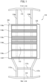
- FIG. 1 is a schematic view for explaining a structure of the car body floor 110 of an automobile according to the present embodiment and a plan view of the car body floor 110 seen from above.
- FIG. 2 is a view of the car body floor 110 seen from below.
- the car body floor 110 has a floor panel 112, floor cross members 114a to 114f, front bumper 115, front side members 116a, 116b, rear side members 117a, 117b, rear bumper 119, and side sills 120.
- the side sills 120 extend on the left and right side surfaces of the automobile in the front-back direction (vehicle length direction) of the automobile.
- the floor cross members 114a to 114f extend in the left-right direction (vehicle width direction) of the automobile.
- the floor cross members 114a to 14f are joined at the two end parts to the left and right side sills 120 by welding, riveting, bolting, etc. (below, referred to as "welding etc.")
- the floor cross members 114b to 114e are arranged extending in the vehicle width direction in the region surrounded by the left and right side sills 120, floor cross member 114a, and floor cross member 114f.
- a floor panel 112 is arranged below the floor cross members 114b to 114e.
- the floor panel 112 is fastened to the floor cross members 114a to 114f and side sills 120 by welding etc.
- the floor cross members 114a to 114f may all be comprised of hat shape members (hat shape cross-section members). Further, the floor cross members 114a to 114f may also be comprised of hollow tubular members and may have rectangular shaped cross-sections perpendicularly interesting the longitudinal direction.
- two front side members 116a, 116b extend in the vehicle length direction.
- the rear side end parts of the front side members 116a, 116b abut against the floor cross member 114f and are fastened by welding etc. to the floor cross member 114f.
- the top surfaces of the front side members 116a, 116b may abut against the floor panel 112 and may be fastened to the floor panel 112 by welding etc.
- two rear side members 117a, 117b extend in the vehicle length direction.
- the end parts of the rear side members 117a, 117b at the front side are fastened by welding etc. to the floor cross member 114f.
- the rear bumper 119 is fastened.
- a cross member 117c connecting the rear side member 117a and the rear side member 117b is arranged between the rear side members 117a, 117b in the front-rear direction.
- the end parts of the cross member 117c are respectively fastened by welding etc. to the rear side member 117a and rear side member 117b.
- the front side members 116a, 116b, rear side member 117a, 117b, and other members are members mainly responsible for absorbing energy at the time of collision when the vehicle is involved in a collision. Greater compactness and higher efficiency are being strongly demanded.
- the inventors discovered to place soft parts in ranges near bending inducing parts of these members to achieve both elimination of weakening of the members along with bending deformation and avoidance of increased weight. According to the present invention, it is possible to decrease the weakening of these members accompanying bending deformation without adding reinforcing members.
- FIG. 3 is a perspective view showing the configuration of a columnar member 100 according to an embodiment of the present invention.
- the columnar member 100 is particularly suitable for application to the front side members 116a, 116b or the rear side members 117a, 117b among the members forming the car body floor 110.
- the columnar member 100 may also be applied to the floor cross members 114a to 114f or the side sills 120 or other component elements of the car body floor 110 shown in FIG. 1 .
- the columnar member 100 may also be applied to the vehicle center pillar, A-pillar, B-pillar, or other component elements other than the car body floor 110.
- the columnar member 100 has at least a top plate 12 and two vertical walls 14, 16 connected with the top plate 12 at the ridge parts of the two side edges 12a, 12b of the top plate 12 and extending along the ridge parts.
- the columnar member 100 has a hat shape member 10 and a plate-shaped member 30 will be used as an example in the explanation.
- the hat shape member 10 and the plate-shaped member 30 are, for example, formed from steel sheets.
- the hat shape member 10 is provided with a plate shaped top plate 12, vertical walls 14, 16 connected to the top plate 12 at ridge parts of the two side edges 12a, 12b of the top plate 12 and extending along the ridge parts, and flange parts 18, 20 extending along the edge parts 14a, 16a at the opposite sides of the vertical walls 14, 16.
- the direction of the main axis Om shown in FIG. 3 shows the longitudinal direction in which the columnar member 100 extends.
- the main axis Om may be a line passing through the center of gravity of the cross-section perpendicular to the longitudinal direction of the columnar member 100. Note that, the direction in which the columnar member 100 extends is not limited to a straight direction.
- the columnar member 100 may also extend in any curved direction.
- At least part of the top plate 12 of the hat shape member 10 is formed with a bend inducing part 22.
- the vertical wall 14 is formed with a soft part 14b.
- the vertical wall 16 is formed with a soft part 16b.
- the soft parts 14b, 16b are provided at positions corresponding to the bend inducing part 22 in the direction along the main axis Om, that is, the direction of extension of the columnar member 100 (longitudinal direction of columnar member 100).
- “provided at positions corresponding to” include the case where the soft parts 14b, 16b are provided at the same positions as the bend inducing part 22 in the direction of extension of the columnar member 100 and the case where at least part of the ranges in which the soft parts 14b, 16b are provided overlap the range in which the bend inducing part 22 is provided in the direction of extension of the columnar member 100.
- FIG. 4 is a cross-sectional view showing a cross-section (transverse section) cut at a plane vertical to a longitudinal direction of the direction of the main axis Om of the columnar member 100 at the position of the bend inducing bead 22.
- the transverse section of the hat shape member 10 is substantially hat shaped.
- the plate-shaped member 30 is joined to the flange parts 18, 20 of the hat shape member 10 by spot welding, line welding, etc.
- the front side members 116a, 116b or the rear side member 117a, 117b forming the car body floor 110 are subjected to a large impact force in the vehicle length direction and deform by compression when the automobile is involved in a collision. If the columnar members 100 are used for the front side members 116a, 116b or the rear side members 117a, 117b, when subjected to a large impact force in the vehicle length direction due to a collision, a compressive load acts in the direction of the main axis Om of the columnar members 100 and the columnar members 100 deform by bending. The energy of the collision is absorbed by bending deformation of the columnar members 100.
- the bend inducing part 22 is formed for providing an easily bendable location at the columnar member 100 and becomes a starting point for bending of the columnar member 100 when the columnar member 100 receives a compressive load in the direction of the main axis Om. Due to this, when the columnar member 100 is subjected to a compressive load, the columnar member 100 deforms by bending in a certain deformation mode envisioned in advance. Therefore, when the columnar member 100 is subjected to a compressive load, unenvisioned deformation of the columnar member 100 is suppressed and safety is secured.
- a groove-shaped recess is formed in the top plate 12 in the direction perpendicular to the main axis Om at the position of the bend inducing part 22 at the inside of the bend.
- the more the columnar member 100 deforms and the greater the bend the narrower the width of the groove-shaped recess and the closer the distance between the facing inside walls of the groove-shaped recess. Further, if the facing inside walls of the groove-shaped recess collide with each other, the columnar member 100 will stop bending temporarily and the decreasing reaction force will start to increase.
- the soft parts 14b, 16b are provided at the two vertical walls 14, 16 of the hat shape member 10 at positions adjoining the ridge parts in a direction perpendicular to the top plate 12 and corresponding to the bend inducing part in the direction of extension of the columnar member 100.
- the soft parts 14b, 16b are comprised as parts lower in yield strengths (or tensile strengths) than parts adjoining the soft parts 14b, 16b at the vertical walls 14, 16 of the hat shape member 10.
- the soft parts 14b, 16b are provided so as to cause earlier formation of the groove-shaped recess, cause the facing inside walls of the groove shape to collide with each other earlier in the bending deformation, and suppress the decrease in the reaction force of the columnar member 100 in the process of bending deformation of the columnar member 100.
- the soft parts 14b, 16b are formed by selective hardening in hot stamping or partial tempering to soften parts of the vertical walls 14, 16.
- the soft parts 14b, 16b have strengths of 0.2 to 0.8 time of the base member strength (yield strength) at other parts of the steel sheet, preferably 0.2 to 0.6 time.
- the soft parts 14b, 16b are made rectangular shapes in a plan view seen from a perspective in a direction vertical to the vertical walls 14, 16.
- the maximum lengths I of the soft parts 14b, 16b in the direction of extension of the columnar member 100 (direction along main axis Om) are made 0.01 time to 0.15 time the heights H of the vertical walls 14, 16.
- the facing inside walls of the groove shape collide with each other early in the bending deformation and the facing inside walls of the groove shape collide with each other in stages over several times, so the drop in the reaction force is suppressed and the amount of absorption of impact energy increases.
- the lengths I of the soft parts 14b, 16b in the direction along the main axis Om are not made 0.01 time to 0.15 time the heights H of the vertical walls 14, 16, the facing inside walls of the groove shape do not collide with each other early in the bending deformation and the facing inside walls of the groove shape do not collide with each other in stages over several times, so the reaction force of the columnar member 100 falls and the amount of absorption of impact energy decreases.
- FIG. 6A to FIG. 6C are schematic views showing in time series the states of progression of bending deformation of a columnar member 100 when a columnar member 100 with lengths I of the soft parts 14b, 16b in the direction along the main axis Om made 0.01 time to 0.15 time the heights H of the vertical walls 14, 16 is subjected to a compressive load in the direction of the main axis Om.
- the positions of the one-dot chain lines show the positions of the bend inducing parts 22.
- FIG. 6A shows tools 40 for applying a compressive load to the columnar member 100.
- shafts are inserted into holes 42 of the tools 40 at the two ends of the columnar member 100 and the deformation in the case where the shafts are made to approach each other is analyzed.
- FIG. 6A shows the state when beginning to apply a compressive load in the longitudinal direction of the columnar member 100.
- the surface of the top plate 12 of the hat shape member 10 and the surface of the plate-shaped member 30 are maintained as flat surfaces and the columnar member 100 does not yet bend.
- the reaction force of the columnar member 100 when a compressive load is applied increases until the columnar member 100 bends.
- the shafts inserted into the holes 42 are made to approach each other so that a compressive load is applied in the longitudinal direction of the columnar member 100.
- the columnar member 100 starts to bend at the position of the bend inducing part 22, wrinkle-like bulges 14d, 16d are formed at the vertical walls 14, 16 and a groove-shaped recess 13d is formed at the top plate 12 at the position of the bend inducing part 22 at the inside of the bend.
- projecting parts 13c are formed at the top parts of the soft parts 14b, 16b.
- FIG. 7 is a schematic view showing a state of a vicinity of a bend inducing part 22 of the top plate 12 of the columnar member 100 seen from above at the timing shown in FIG. 6C .
- projecting parts 13c are formed at the top parts of the vertical walls 14, 16.
- the facing inside walls collide with each other at the back sides of the projecting parts 13c.
- the facing inside walls 13e of the groove-shaped recesses 13d collide with each other. Due to this, the drop in the reaction force of the columnar member 100 is further suppressed. Further, by the facing inside walls of the groove shapes at the back sides of the projecting parts 13c colliding with each other and the facing inside walls 13e of the groove-shaped recesses 13d at the surface side of the top plate 12 colliding with each other in stages at different timings, the drop in reaction force is suppressed by the plurality of collisions and the amount of absorption of the impact energy is increased.
- FIG. 8 is a schematic view showing the state of a vicinity of a bend inducing part 22 of the top plate 12 of the columnar member 104 seen from above at the same timing (after the elapse of a certain time T from the start of application of the compressive load) as FIG. 6C in the case where a columnar member 104 with lengths I of soft parts 14b, 16b in the direction along the main axis Om not made 0.01 time to 0.15 time the heights H of the vertical walls 14, 16 is subjected to a compressive load under the same conditions of FIG. 6A to FIG. 6C .
- the soft parts 14b, 16b end up deforming to recessed shapes overall and projecting parts 13c are not formed at the top parts of the soft parts 14b, 16b, so the facing inside walls of the groove shape do not collide with each other at the back sides of the projecting parts 13c. Further, the facing inside walls 13b of the groove-shaped recess 13a are separated by the width d1. At that time, the facing inside walls 13b do not collide with each other.
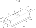
- FIG. 5 is a perspective view showing the configuration of the columnar member 102 of the base member model at which soft parts 14b, 16b are not provided.
- the constitution of the columnar member 102 shown in FIG. 5 is the same as the columnar member 100 according to the present embodiment shown in FIG. 3 other than the point of the soft parts 14b, 16b not being provided.
- FIG. 9 is a graph showing the relationship between the stroke (abscissa) and reaction force (ordinate) if applying a compressive load in the direction along the main axis Om to the columnar member 100 according to the present embodiment and the columnar member 102 of the base member model with lengths I of soft parts 14b, 16b in the direction of the main axis Om made 0.1 time the heights H of the vertical walls 14, 16.
- the characteristic C1 shown by the solid line shows the characteristic of the stroke and reaction force at the columnar member 100 of the present embodiment when making the lengths I of the soft parts 14b, 16b in the direction along the main axis Om 0.1 time the heights H of the vertical walls 14, 16.
- the characteristic C2 shown by the broken line shows the characteristic of the stroke and reaction force at the columnar member 102 of the base member model.
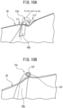
- FIG. 10A to FIG. 10C and FIG. 11A to FIG. 11C are views showing states of bending deformation of columnar members 100, 102 at the timings of strokes S1, S2, and S3 in the characteristics of the stroke and reaction force shown in FIG. 9 .
- FIG. 10A to FIG. 10C are views showing states of bending deformation of columnar members 100 of the present embodiment with lengths I of soft parts 14b, 16b in the direction of the main axis Om made 0.1 time the heights H of the vertical walls 14, 16.
- FIG. 11A to FIG. 11C show the states of bending deformation of columnar members 102 of the base member model.
- FIG. 11C show the states where columnar members 100, 102 broke along the one-dot chain lines I-I' shown in FIG. 3 and FIG. 5 at the respective timings.
- FIG. 10B is a cross-sectional view showing the state where a columnar member 100 broke along the one-dot chain line II-II' shown in FIG. 10A .
- FIG. 10A and FIG. 11A show states of bending deformation of columnar members 100, 102 at the timing of the stroke S1 shown in FIG. 9 .
- FIG. 10C and FIG. 11B show states of bending deformation of columnar members 100, 102 at the timing of the stroke S2 shown in FIG. 9 .
- FIG. 11C shows a state of bending deformation of a columnar member 102 at the timing of the stroke S3 shown in FIG. 9 .
- a groove-shaped recess 13d is formed in the top plate 12.
- the lengths I of the soft parts 14b, 16b in the direction along the main axis Om are not made 0.1 time the heights H of the vertical walls 14, 16, so due to bending of the vertical walls 14, 16 at the positions of the soft parts 14b, 16b, projecting parts 13c bulging outside are formed at the top parts of the vertical walls 14, 16.
- a groove-shaped recess 13a is formed in the top plate 12, but since there are no soft parts 14b, 16b with lengths I made 0.01 time to 0.15 time the heights H of the vertical walls 14, 16, no projecting parts 13c are formed at the columnar member 100 of the present embodiment. Until the stroke reaches S1, at both the characteristic C1 and the characteristic C2, the reaction force continuously falls along with an increase of the stroke.
- the stroke reaches S1
- the back sides of the projecting parts 13c formed at the top parts of the vertical walls 14, 16 become groove shaped.
- the facing inside walls 13f of the groove shape collide with each other (first collision).
- the lengths I of the soft parts 14b, 16b are made 0.1 time the heights H of the vertical walls 14, 16, so projecting parts 13c bulging to the outside are formed at the top parts of the vertical walls 14, 16.
- the facing inside walls 13f of the groove shape collide with each other at the rear sides of the projecting parts 13c, so it is possible to cause a collision early. Due to this, at the solid line characteristic C1 shown in FIG. 9 , the reaction force temporarily increases after the stroke S1. After that, until the stroke S2, the reaction force of the characteristic C1 gradually decreases.
- the reaction force generated at the time of the same stroke ends up falling more and a larger space is required for absorbing the same impact energy as the columnar member 100 of the present embodiment.
- the area of the region surrounded by the characteristic C1 or the characteristic C2 and the abscissa shows the magnitude of the impact energy absorbed by bending deformation of the columnar member 100.
- the characteristic C1 of the columnar member 100 of the present embodiment where soft parts 14b, 16b are provided at the vertical walls 14, 16 and the lengths I of the soft parts 14b, 16b in the direction of the main axis Om are made 0.1 time the heights H of the vertical walls 14, 16, compared with the characteristic C2 of the columnar member 102 of the base member model not provided with the soft parts 14b, 16b at the vertical walls 14, 16, impact energy larger by exactly the amount of the area shown by the hatching is absorbed.
- a bend inducing part 22 comprised of a recessed bead was shown, but the bend inducing part 22 need only be a portion acting as the starting point of bending of the columnar member 100 and a part with a strength lower than the parts adjoining the bend inducing part 22 at the top plate 12.
- the bend inducing part 22 may also be comprised of a projecting part, hole, or point of change of curvature of the columnar member 100 provided at the top plate 12. Further, the bend inducing part 22 may also be comprised of a portion where the material strength of the columnar member 100 locally falls.
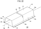
- FIG. 19 is a perspective view showing an example where the bend inducing part 22 is comprised of a hole provided at the top plate 12.
- FIG. 20 is a perspective view showing an example where the bend inducing part 22 is comprised between four recessed beads 23 extending in the direction of the main axis Om.
- the bending rigidity of the columnar member 100 is determined by the shape of the cross-section perpendicularly intersecting the main axis Om. Bending deformation easily occurs at the point of change of the cross-sectional secondary moment.
- the cross-sectional secondary moment of the cross-section perpendicularly intersecting the main axis Om changes at the position of the bend inducing part 22, so if a compressive load is applied in the direction of the main axis Om of the columnar member 100, the bend inducing part 22 becomes the starting point of the bending.
- FIG. 19 is an example where the cross-sectional secondary moment changes to a low at the bend inducing part 22, while FIG. 20 is an example where the cross-sectional secondary moment changes to a high at the recessed beads 23 and as a result the cross-sectional secondary moment changes to a low at the bend inducing part 22.
- the recessed beads 23 provided at the top plate 12 are forms of the reinforcing parts.
- the top plate 12 may have at least two reinforcing parts (beads 23) provided separated from each other in the direction of extension of the columnar member 100, and the bend inducing part 22 may be positioned between reinforcing parts separated in the direction of extension of the columnar member 100.
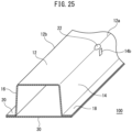
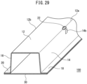
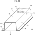
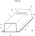
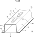
- the bend inducing part 22 may be comprised of a circular projecting part provided at the top plate 12. Further, as shown in FIG. 32 , the bend inducing part 22 may be comprised of a plurality of projecting parts provided at the top plate 12. In this case, for example, the plurality of projecting parts may be provided aligned in a direction perpendicular to the longitudinal direction of the columnar member 100. Further, as shown in FIG. 33 , the bend inducing part 22 may be comprised of a projecting part provided at the top plate 12 and extending in a direction perpendicular to the longitudinal direction of the columnar member 100. Further, as shown in FIG.
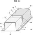
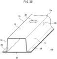
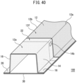
- the hat shape member 10 of the columnar member 100 may be provided with a first sheet thickness part 12c and a second sheet thickness part 12d, the thickness of the steel sheet may differ between the first sheet thickness part 12c and the second sheet thickness part 12d, and the bend inducing part 22 may be a part at the thin side of the sheet thickness at the boundary of the first sheet thickness part 12c and the second sheet thickness part 12d (part between boundary and broken line shown in FIG. 36 ). Note that, the first sheet thickness part 12c is thinner in sheet thickness than the second sheet thickness part 12d. Further, as shown in FIG.
- the spot welding pitch was made 30 mm while the weld diameter of the spot welding was made 6 mm. Further, the member length (L1 shown in FIG. 6A ) was made 340 mm, the height of the hat shape member 10 (H shown in FIG. 4 ) was made 72 mm, and the width of the plate-shaped member 30 (W shown in FIG. 4 ) was made 160 mm. This was made common for all of the columnar members 100 and the columnar member 102 of the base member model.
- the reaction force of the characteristic C1 was the largest, then the reaction force was larger in order of the characteristic C3 and the characteristic C4. From the results, if I/H is 0.1 or more and 0.33 or less, it is learned that the drop in the reaction force can be suppressed without regard as to the heights "h" (mm) of the soft parts 14b, 16b.
- the lengths I in the direction of the main axis Om are not made 0.01 time to 0.15 time the heights H of the vertical walls 14, 16, so if applying a compressive load, the soft parts 14b, 16b easily deform and the reaction force became lower than the base member model from right after the stroke S0.
- FIG. 15 is a graph showing a relationship between a stroke and reaction force for every variation of strength of the soft parts 14b, 16b.
- Table 2 the values of I/H and h/H were respectively made fixed values of 0.10 and 0.33, the ratios of the yield strength of the soft parts 14b, 16b with respect to the yield strength of the base member other than the soft parts 14b, 16b were made 0.2, 0.4, 0.6, 0.8, and 0.9, and forced displacement was given to columnar members 100 under the same conditions as the above.
- the maximum reaction force of the characteristic C1 (first occurring peak reaction force corresponding to reaction force at stroke S0 where columnar members 100, 102 bent) was the smallest.
- the maximum reaction force was larger in the order of the characteristics C7, C8, C9, and C10. The result was obtained that if the lengths I of the soft parts 14b, 16b are made 0.01 time to 0.15 time of the heights H of the vertical walls 14, 16, the smaller the strength ratio, the smaller the first occurring peak reaction force. Therefore, it is learned that the amount of energy absorption rises by the first peak reaction force rising the greater the strength ratio.
- a columnar member 100 was given forced displacement and the relationship of the sizes of the soft parts 14b, 16b (lengths I, heights "h"), the strength ratio with respect to the base member, and the angles of the vertical walls 14, 16 ( ⁇ shown in FIG. 4 ) with the energy absorption performance of the columnar member 100 were studied by comparison with the amount of energy absorption at the base member model.
- the sizes of the soft parts 14b, 16b were expressed as ratios with respect to the heights H of the vertical walls 14, 16. Variations of ratios 0.1, 0.2, 0.25, 0.33, 0.4, 0.5, 0.75, and 1.0 were prepared for the lengths I and heights "h". The variations of the angles of the vertical walls were made the five types of 50°, 60°, 70°, 80°, and 90°. Further, the variations of the strength ratios were made 0.2, 0.3, 0.4, 0.5, 0.6, 0.7, 0.8, and 0.9.
- the ratio of the height "h” to the height H was made 0.33, the angle of the vertical walls was made 80°, and the strength ratio was made 0.2.
- the ratio of the length I to the height H was made 0.1, the angle of the vertical walls was made 80°, and the strength ratio was made 0.2.
- the ratio of the length I to the height H was made 0.1, the ratio of the height "h” to the height H was made 0.33, and the strength ratio was made 0.2.
- the ratio of the length I to the height H was made 0.1, the ratio of the height "h” to the height H was made 0.33, and the angle of the vertical walls was made 80°.
- FIG. 16A to FIG. 16D show the results of the study.
- the ordinates show the ratio of amount of energy absorption of the columnar member 100 being studied to the amount of energy absorption at the base member model (ratio of amount of energy absorption). If this ratio is larger than 1, the amount of energy absorption becomes larger than the base member model.
- FIG. 16A shows the relation of the lengths I of the soft parts 14b, 16b and the ratio of amount of energy absorption.
- the abscissa shows the ratio I/H of the lengths I (mm) to the heights H.
- I/H is 0.01 or more and 0.15 or less
- the ratio of amount of energy absorption with respect to the base member model became larger than 1.
- the lengths I of the soft parts 14b, 16b in the direction of the main axis Om is not made 0.01 time to 0.15 time the heights H of the vertical walls 14, 16, so the ratio of amount of energy absorption with respect to the base member became smaller than 1. More preferably, if I/H is 0.01 or more and 0.11 or less, the ratio of amount of energy absorption with respect to the base member became remarkably larger.
- FIG. 16B shows the relationship of the heights "h” of the soft parts 14b, 16b and the ratio of amount of energy absorption.
- the abscissa shows the ratio h/H of the heights "h" (mm) to the heights H.
- the ratio of amount of energy absorption with respect to the base member became larger than 1. More preferably, if h/H is 0.15 or more and 0.4 or less, the ratio of amount of energy absorption with respect to the base member became remarkably larger.
- FIG. 16C shows the relationship of the angle of the vertical walls and the ratio of amount of energy absorption.
- the abscissa shows the angle of the vertical walls.
- the ratio of amount of energy absorption with respect to the base member model became larger than 1.
- FIG. 16D shows the relationship of the strength ratio and the ratio of amount of energy absorption.
- the abscissa shows the strength ratio.
- the strength ratio was 0.9, no first collision occurs, so as a result no improvement in the amount of energy absorption could be found, but if the strength ratio was 0.2 or more and 0.8 or less, the ratio of amount of energy absorption with respect to the base member model was larger than 1. More preferably, if the strength ratio was 0.3 or more and 0.7 or less, the ratio of amount of energy absorption with respect to the base member became remarkably larger.
- the positions of the top ends of the soft parts 14b, 16b match the positions of the bottom ends of the ridge parts 15 at the distance of h1 from the top plate 12. According to this constitution, if the columnar member 100 is subjected to a compressive load, at the ridge parts 15, a large reaction force is generated and the facing inside walls 13f at the back side of the projecting part 13c can be made to collide with each other earlier.
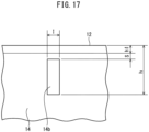
- FIG. 17 is a schematic view showing in detail a soft part 14b provided at a vertical wall 14 in the same way as FIG. 12 and shows the example where a space "s" is provided between the positions of the top ends of the soft parts 14b, 16b and the positions of the bottom ends of the ridge parts 15.
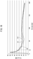
- FIG. 18 in the same way as FIG. 9 , is a graph showing relationships between the stroke and the reaction force of the columnar members 100, 102 and shows the characteristic C11 at the columnar member 100 when making the space "s" shown in FIG. 17 5 mm together with the characteristic C1 and the characteristic C2 of FIG. 9 .
- the I/H of the columnar member 100 when making the space "s" 5 mm, the lengths of the soft parts 14b, 16b of the vertical walls 14, 16 in the height H direction, the strength ratio, and the angle of the vertical walls were made the same as the columnar member 100 giving the characteristic C1.
- the positions of the top ends of the soft parts 14b, 16b and the positions of the bottom ends of the ridge parts 15 need not necessarily be made to match, so the freedom of design of the soft parts 14b, 16b becomes greater and a reduction in the production costs can be expected.
Landscapes
- Engineering & Computer Science (AREA)
- Chemical & Material Sciences (AREA)
- Combustion & Propulsion (AREA)
- Transportation (AREA)
- Mechanical Engineering (AREA)
- Body Structure For Vehicles (AREA)
Claims (8)
- Säulenförmiges Element (100), mit mindestens:einer oberen Platte (12); undzwei vertikalen Wänden (14, 16), die mit der oberen Platte (12) an Kantenabschnitten an beiden Seitenrändern der oberen Platte (12) verbunden sind und sich entlang der Kantenabschnitte erstrecken, wobeidas säulenförmige Element (100)mindestens an einem Abschnitt der oberen Platte (12) einen biegungsinduzierenden Teil (22) aufweist, undder biegungsinduzierende Teil (22) ein Teil ist, der eine geringere Festigkeit hat als ein Teil, das dem biegungsinduzierenden Teil (22) an der oberen Platte (12) benachbart ist, unddadurch gekennzeichnet, dassjede der beiden vertikalen Wände (14, 16) einen weichen Teil (14b, 16b) an einer Position aufweist, die dem Kantenabschnitt benachbart ist und dem biegungsinduzierenden Teil (22) in einer Erstreckungsrichtung des säulenförmigen Elements (100) entspricht, unddadurch, dassjeder der weichen Teile (14b, 16b) eine Streckgrenze aufweist, die niedriger ist als diejenige eines Teils, der jedem der weichen Teile (14b, 16b) an der vertikalen Wand (14, 16) benachbart ist, wobei jede maximale Länge (I) jedes der weichen Teile (14b, 16b) in der Erstreckungsrichtung des säulenförmigen Elements (100) das 0,01-fache bis 0,15-fache einer Höhe jeder der beiden vertikalen Wände (14, 16) beträgt.
- Säulenförmiges Element nach Anspruch 1, wobei jede der Längen jedes der weichen Teile in der Höhenrichtung der vertikalen Wand das 0,15-fache bis 0,9-fache der Höhe jeder der beiden vertikalen Wände (14, 16) beträgt.
- Säulenförmiges Element nach Anspruch 1 oder 2, wobei jedes Verhältnis der Streckgrenzen jedes der weichen Teile (14b, 16b) zur Streckgrenze jedes der Teile, die jedem der weichen Teile (14b, 16b) an den vertikalen Wänden (14, 16) benachbart sind, 0,2 bis 0,8 beträgt.
- Säulenförmiges Element nach einem der Ansprüche 1 bis 3, wobei Endabschnitte der weichen Teile (14b, 16b) an den Seiten der oberen Platte (12) an Endabschnitten der Kantenabschnitte angeordnet sind, die die obere Platte (12) und die vertikalen Wände (14, 16) an den Seiten der vertikalen Wand (14, 16) verbinden.
- Säulenförmiges Element nach einem der Ansprüche 1 bis 4, wobei der biegungsinduzierende Teil (22) einen vertieften Teil, ein Loch oder einen hervorstehenden Teil aufweist, das/der an der oberen Platte (12) vorgesehen ist.
- Säulenförmiges Element nach einem der Ansprüche 1 bis 4, wobeidie obere Platte (12) mindestens zwei Verstärkungsteile aufweist, die in der Erstreckungsrichtung des säulenförmigen Elements (100) voneinander getrennt vorgesehen sind, undder biegungsinduzierende Teil (22) zwischen den Verstärkungsteilen angeordnet ist, die in der Erstreckungsrichtung des säulenförmigen Elements (100) voneinander getrennt vorgesehen sind.
- Säulenförmiges Element nach einem der Ansprüche 1 bis 5, wobei der biegungsinduzierende Teil (22) einen vertieften Teil, ein Loch oder einen hervorstehenden Teil aufweist, das/der am Kantenabschnitt vorgesehen ist, der die obere Platte (12) und die vertikale Wand (14, 16) verbindet.
- Säulenförmiges Element nach einem der Ansprüche 1 bis 7, das ein vorderseitiges Bauteil (116a, 116b) oder ein rückseitiges Bauteil eines Fahrzeugs (117a, 117b) bildet.
Applications Claiming Priority (2)
| Application Number | Priority Date | Filing Date | Title |
|---|---|---|---|
| JP2020085434 | 2020-05-14 | ||
| PCT/JP2021/018286 WO2021230331A1 (ja) | 2020-05-14 | 2021-05-13 | 柱状部材 |
Publications (3)
| Publication Number | Publication Date |
|---|---|
| EP4151506A1 EP4151506A1 (de) | 2023-03-22 |
| EP4151506A4 EP4151506A4 (de) | 2023-11-01 |
| EP4151506B1 true EP4151506B1 (de) | 2025-02-26 |
Family
ID=78524468
Family Applications (1)
| Application Number | Title | Priority Date | Filing Date |
|---|---|---|---|
| EP21805027.6A Active EP4151506B1 (de) | 2020-05-14 | 2021-05-13 | Säulenförmiges element |
Country Status (5)
| Country | Link |
|---|---|
| US (1) | US12509153B2 (de) |
| EP (1) | EP4151506B1 (de) |
| JP (1) | JP7759316B2 (de) |
| CN (1) | CN115087586B (de) |
| WO (1) | WO2021230331A1 (de) |
Families Citing this family (8)
| Publication number | Priority date | Publication date | Assignee | Title |
|---|---|---|---|---|
| JP7824093B2 (ja) * | 2022-02-24 | 2026-03-04 | 株式会社Subaru | 車体構造部材及び車体構造 |
| JP7900691B2 (ja) * | 2023-10-18 | 2026-08-05 | 日本製鉄株式会社 | 衝撃吸収部材 |
| WO2025084411A1 (ja) * | 2023-10-18 | 2025-04-24 | 日本製鉄株式会社 | 衝撃吸収部材及び車体部品 |
| JP7890617B2 (ja) * | 2023-10-18 | 2026-07-15 | 日本製鉄株式会社 | 衝撃吸収部材及び車体部品 |
| JP2025069604A (ja) * | 2023-10-18 | 2025-05-01 | 日本製鉄株式会社 | 衝撃吸収部材 |
| JP7900690B2 (ja) * | 2023-10-18 | 2026-08-05 | 日本製鉄株式会社 | 衝撃吸収部材及び車体部品 |
| JP2025069603A (ja) * | 2023-10-18 | 2025-05-01 | 日本製鉄株式会社 | 衝撃吸収部材 |
| JP7900689B2 (ja) * | 2023-10-18 | 2026-08-05 | 日本製鉄株式会社 | 衝撃吸収部材 |
Family Cites Families (17)
| Publication number | Priority date | Publication date | Assignee | Title |
|---|---|---|---|---|
| JPH07119892A (ja) * | 1993-10-27 | 1995-05-12 | Nissan Motor Co Ltd | 強度部材 |
| JP2010236560A (ja) | 2009-03-30 | 2010-10-21 | Nisshin Steel Co Ltd | 衝撃吸収特性に優れた構造部材の製造方法 |
| JP5251692B2 (ja) | 2009-04-08 | 2013-07-31 | トヨタ自動車株式会社 | 車両用骨格部材 |
| CN102893049B (zh) * | 2010-08-26 | 2015-01-21 | 新日铁住金株式会社 | 冲击吸收部件 |
| JP5691460B2 (ja) * | 2010-12-07 | 2015-04-01 | トヨタ自動車株式会社 | 車両のピラー構造 |
| ES2553860T3 (es) * | 2011-03-30 | 2015-12-14 | Nippon Steel & Sumitomo Metal Corporation | Miembro metálico hueco columniforme |
| JP6268780B2 (ja) | 2013-07-16 | 2018-01-31 | 新日鐵住金株式会社 | 柱状部材 |
| JP2015105024A (ja) | 2013-11-29 | 2015-06-08 | トヨタ自動車株式会社 | 車体骨格部材 |
| US9415810B2 (en) * | 2013-12-31 | 2016-08-16 | Ford Global Technologies, Llc | Vehicle roof structure including a cast node |
| BR112018006743A2 (pt) * | 2015-10-09 | 2018-10-16 | Nippon Steel & Sumitomo Metal Corporation | membro estrutural e veículo |
| US10633031B2 (en) | 2015-12-18 | 2020-04-28 | Autotech Engineering S.L. | B-pillar central beam and method for manufacturing |
| JP7135274B2 (ja) | 2016-03-03 | 2022-09-13 | 日本製鉄株式会社 | 車両用構造部材 |
| DE102016103962B3 (de) * | 2016-03-04 | 2017-03-02 | Benteler Automobiltechnik Gmbh | B-Säule mit partiellen Festigkeitseigenschaften |
| BR112019010689A2 (pt) * | 2017-01-11 | 2019-10-01 | Nippon Steel Corp | elemento estrutural e elemento estrutural para veículos |
| JP6855851B2 (ja) | 2017-03-13 | 2021-04-07 | 日本製鉄株式会社 | 車両用構造部材 |
| JP6376318B1 (ja) * | 2017-03-24 | 2018-08-22 | 新日鐵住金株式会社 | ハット部材およびその製造方法 |
| JP7035742B2 (ja) * | 2018-04-09 | 2022-03-15 | 日本製鉄株式会社 | 車両用構造部材 |
-
2021
- 2021-05-13 WO PCT/JP2021/018286 patent/WO2021230331A1/ja not_active Ceased
- 2021-05-13 JP JP2022522208A patent/JP7759316B2/ja active Active
- 2021-05-13 CN CN202180013533.1A patent/CN115087586B/zh active Active
- 2021-05-13 US US17/924,623 patent/US12509153B2/en active Active
- 2021-05-13 EP EP21805027.6A patent/EP4151506B1/de active Active
Also Published As
| Publication number | Publication date |
|---|---|
| EP4151506A4 (de) | 2023-11-01 |
| JP7759316B2 (ja) | 2025-10-23 |
| US20230182819A1 (en) | 2023-06-15 |
| CN115087586A (zh) | 2022-09-20 |
| EP4151506A1 (de) | 2023-03-22 |
| CN115087586B (zh) | 2024-11-26 |
| US12509153B2 (en) | 2025-12-30 |
| JPWO2021230331A1 (de) | 2021-11-18 |
| WO2021230331A1 (ja) | 2021-11-18 |
Similar Documents
| Publication | Publication Date | Title |
|---|---|---|
| US12509153B2 (en) | Columnar member | |
| US8641129B2 (en) | Twelve-cornered strengthening member | |
| CN100476233C (zh) | 碰撞吸收构件 | |
| CN104245482B (zh) | 汽车车体 | |
| CN107792183B (zh) | 车辆的后部车体构造 | |
| JP4045846B2 (ja) | 衝突エネルギー吸収部材 | |
| JPWO2018131516A1 (ja) | 構造部材及び車両用構造部材 | |
| US10695817B2 (en) | Thirty-six-cornered strengthening member | |
| US10065682B1 (en) | Thirty-two-cornered strengthening member | |
| JP4039032B2 (ja) | 衝突エネルギー吸収部材 | |
| JP6565291B2 (ja) | 衝撃吸収部材、車体および衝撃吸収方法 | |
| JP4362952B2 (ja) | バンパステイ | |
| JP7453538B2 (ja) | 柱状部材 | |
| US10144454B1 (en) | Thirty-six cornered vehicle beam | |
| CN114174089B (zh) | 汽车外装面板的加强构造 | |
| JP2024148936A (ja) | 軸圧潰衝撃吸収部材 | |
| JP2019166855A (ja) | 車両用構造部材及び車両 | |
| JPH115564A (ja) | 車両のサイドメンバ構造 | |
| CN120129633A (zh) | 骨架构件 | |
| JP7252443B2 (ja) | 車体部材、および、車体構造 | |
| JP7842371B2 (ja) | 自動車構造部材 | |
| JP7779362B1 (ja) | 自動車用衝突エネルギー吸収部品 | |
| JP4706656B2 (ja) | バンパステイ | |
| KR102202098B1 (ko) | 차량용 시트 크로스 멤버 조립체 | |
| JP4766075B2 (ja) | バンパステイ |
Legal Events
| Date | Code | Title | Description |
|---|---|---|---|
| STAA | Information on the status of an ep patent application or granted ep patent |
Free format text: STATUS: THE INTERNATIONAL PUBLICATION HAS BEEN MADE |
|
| PUAI | Public reference made under article 153(3) epc to a published international application that has entered the european phase |
Free format text: ORIGINAL CODE: 0009012 |
|
| STAA | Information on the status of an ep patent application or granted ep patent |
Free format text: STATUS: REQUEST FOR EXAMINATION WAS MADE |
|
| 17P | Request for examination filed |
Effective date: 20221214 |
|
| AK | Designated contracting states |
Kind code of ref document: A1 Designated state(s): AL AT BE BG CH CY CZ DE DK EE ES FI FR GB GR HR HU IE IS IT LI LT LU LV MC MK MT NL NO PL PT RO RS SE SI SK SM TR |
|
| DAV | Request for validation of the european patent (deleted) | ||
| DAX | Request for extension of the european patent (deleted) | ||
| A4 | Supplementary search report drawn up and despatched |
Effective date: 20231005 |
|
| RIC1 | Information provided on ipc code assigned before grant |
Ipc: B62D 25/08 20060101AFI20230928BHEP |
|
| GRAP | Despatch of communication of intention to grant a patent |
Free format text: ORIGINAL CODE: EPIDOSNIGR1 |
|
| STAA | Information on the status of an ep patent application or granted ep patent |
Free format text: STATUS: GRANT OF PATENT IS INTENDED |
|
| INTG | Intention to grant announced |
Effective date: 20240920 |
|
| GRAS | Grant fee paid |
Free format text: ORIGINAL CODE: EPIDOSNIGR3 |
|
| GRAA | (expected) grant |
Free format text: ORIGINAL CODE: 0009210 |
|
| STAA | Information on the status of an ep patent application or granted ep patent |
Free format text: STATUS: THE PATENT HAS BEEN GRANTED |
|
| AK | Designated contracting states |
Kind code of ref document: B1 Designated state(s): AL AT BE BG CH CY CZ DE DK EE ES FI FR GB GR HR HU IE IS IT LI LT LU LV MC MK MT NL NO PL PT RO RS SE SI SK SM TR |
|
| REG | Reference to a national code |
Ref country code: GB Ref legal event code: FG4D |
|
| REG | Reference to a national code |
Ref country code: CH Ref legal event code: EP |
|
| REG | Reference to a national code |
Ref country code: DE Ref legal event code: R096 Ref document number: 602021026866 Country of ref document: DE |
|
| REG | Reference to a national code |
Ref country code: IE Ref legal event code: FG4D |
|
| REG | Reference to a national code |
Ref country code: NL Ref legal event code: MP Effective date: 20250226 |
|
| PG25 | Lapsed in a contracting state [announced via postgrant information from national office to epo] |
Ref country code: RS Free format text: LAPSE BECAUSE OF FAILURE TO SUBMIT A TRANSLATION OF THE DESCRIPTION OR TO PAY THE FEE WITHIN THE PRESCRIBED TIME-LIMIT Effective date: 20250526 |
|
| PG25 | Lapsed in a contracting state [announced via postgrant information from national office to epo] |
Ref country code: FI Free format text: LAPSE BECAUSE OF FAILURE TO SUBMIT A TRANSLATION OF THE DESCRIPTION OR TO PAY THE FEE WITHIN THE PRESCRIBED TIME-LIMIT Effective date: 20250226 |
|
| PG25 | Lapsed in a contracting state [announced via postgrant information from national office to epo] |
Ref country code: PL Free format text: LAPSE BECAUSE OF FAILURE TO SUBMIT A TRANSLATION OF THE DESCRIPTION OR TO PAY THE FEE WITHIN THE PRESCRIBED TIME-LIMIT Effective date: 20250226 |
|
| PG25 | Lapsed in a contracting state [announced via postgrant information from national office to epo] |
Ref country code: ES Free format text: LAPSE BECAUSE OF FAILURE TO SUBMIT A TRANSLATION OF THE DESCRIPTION OR TO PAY THE FEE WITHIN THE PRESCRIBED TIME-LIMIT Effective date: 20250226 |
|
| REG | Reference to a national code |
Ref country code: LT Ref legal event code: MG9D |
|
| PG25 | Lapsed in a contracting state [announced via postgrant information from national office to epo] |
Ref country code: IS Free format text: LAPSE BECAUSE OF FAILURE TO SUBMIT A TRANSLATION OF THE DESCRIPTION OR TO PAY THE FEE WITHIN THE PRESCRIBED TIME-LIMIT Effective date: 20250626 Ref country code: NO Free format text: LAPSE BECAUSE OF FAILURE TO SUBMIT A TRANSLATION OF THE DESCRIPTION OR TO PAY THE FEE WITHIN THE PRESCRIBED TIME-LIMIT Effective date: 20250526 |
|
| PG25 | Lapsed in a contracting state [announced via postgrant information from national office to epo] |
Ref country code: NL Free format text: LAPSE BECAUSE OF FAILURE TO SUBMIT A TRANSLATION OF THE DESCRIPTION OR TO PAY THE FEE WITHIN THE PRESCRIBED TIME-LIMIT Effective date: 20250226 |
|
| PG25 | Lapsed in a contracting state [announced via postgrant information from national office to epo] |
Ref country code: HR Free format text: LAPSE BECAUSE OF FAILURE TO SUBMIT A TRANSLATION OF THE DESCRIPTION OR TO PAY THE FEE WITHIN THE PRESCRIBED TIME-LIMIT Effective date: 20250226 |
|
| PG25 | Lapsed in a contracting state [announced via postgrant information from national office to epo] |
Ref country code: LV Free format text: LAPSE BECAUSE OF FAILURE TO SUBMIT A TRANSLATION OF THE DESCRIPTION OR TO PAY THE FEE WITHIN THE PRESCRIBED TIME-LIMIT Effective date: 20250226 Ref country code: PT Free format text: LAPSE BECAUSE OF FAILURE TO SUBMIT A TRANSLATION OF THE DESCRIPTION OR TO PAY THE FEE WITHIN THE PRESCRIBED TIME-LIMIT Effective date: 20250626 |
|
| PG25 | Lapsed in a contracting state [announced via postgrant information from national office to epo] |
Ref country code: GR Free format text: LAPSE BECAUSE OF FAILURE TO SUBMIT A TRANSLATION OF THE DESCRIPTION OR TO PAY THE FEE WITHIN THE PRESCRIBED TIME-LIMIT Effective date: 20250527 Ref country code: BG Free format text: LAPSE BECAUSE OF FAILURE TO SUBMIT A TRANSLATION OF THE DESCRIPTION OR TO PAY THE FEE WITHIN THE PRESCRIBED TIME-LIMIT Effective date: 20250226 |
|
| REG | Reference to a national code |
Ref country code: AT Ref legal event code: MK05 Ref document number: 1770401 Country of ref document: AT Kind code of ref document: T Effective date: 20250226 |
|
| PG25 | Lapsed in a contracting state [announced via postgrant information from national office to epo] |
Ref country code: SE Free format text: LAPSE BECAUSE OF FAILURE TO SUBMIT A TRANSLATION OF THE DESCRIPTION OR TO PAY THE FEE WITHIN THE PRESCRIBED TIME-LIMIT Effective date: 20250226 |
|
| PG25 | Lapsed in a contracting state [announced via postgrant information from national office to epo] |
Ref country code: SM Free format text: LAPSE BECAUSE OF FAILURE TO SUBMIT A TRANSLATION OF THE DESCRIPTION OR TO PAY THE FEE WITHIN THE PRESCRIBED TIME-LIMIT Effective date: 20250226 |
|
| PG25 | Lapsed in a contracting state [announced via postgrant information from national office to epo] |
Ref country code: DK Free format text: LAPSE BECAUSE OF FAILURE TO SUBMIT A TRANSLATION OF THE DESCRIPTION OR TO PAY THE FEE WITHIN THE PRESCRIBED TIME-LIMIT Effective date: 20250226 |
|
| PG25 | Lapsed in a contracting state [announced via postgrant information from national office to epo] |
Ref country code: IT Free format text: LAPSE BECAUSE OF FAILURE TO SUBMIT A TRANSLATION OF THE DESCRIPTION OR TO PAY THE FEE WITHIN THE PRESCRIBED TIME-LIMIT Effective date: 20250226 |
|
| PG25 | Lapsed in a contracting state [announced via postgrant information from national office to epo] |
Ref country code: AT Free format text: LAPSE BECAUSE OF FAILURE TO SUBMIT A TRANSLATION OF THE DESCRIPTION OR TO PAY THE FEE WITHIN THE PRESCRIBED TIME-LIMIT Effective date: 20250226 |
|
| PG25 | Lapsed in a contracting state [announced via postgrant information from national office to epo] |
Ref country code: EE Free format text: LAPSE BECAUSE OF FAILURE TO SUBMIT A TRANSLATION OF THE DESCRIPTION OR TO PAY THE FEE WITHIN THE PRESCRIBED TIME-LIMIT Effective date: 20250226 Ref country code: CZ Free format text: LAPSE BECAUSE OF FAILURE TO SUBMIT A TRANSLATION OF THE DESCRIPTION OR TO PAY THE FEE WITHIN THE PRESCRIBED TIME-LIMIT Effective date: 20250226 |
|
| PG25 | Lapsed in a contracting state [announced via postgrant information from national office to epo] |
Ref country code: RO Free format text: LAPSE BECAUSE OF FAILURE TO SUBMIT A TRANSLATION OF THE DESCRIPTION OR TO PAY THE FEE WITHIN THE PRESCRIBED TIME-LIMIT Effective date: 20250226 |
|
| PG25 | Lapsed in a contracting state [announced via postgrant information from national office to epo] |
Ref country code: SK Free format text: LAPSE BECAUSE OF FAILURE TO SUBMIT A TRANSLATION OF THE DESCRIPTION OR TO PAY THE FEE WITHIN THE PRESCRIBED TIME-LIMIT Effective date: 20250226 |
|
| REG | Reference to a national code |
Ref country code: DE Ref legal event code: R097 Ref document number: 602021026866 Country of ref document: DE |
|
| REG | Reference to a national code |
Ref country code: CH Ref legal event code: H13 Free format text: ST27 STATUS EVENT CODE: U-0-0-H10-H13 (AS PROVIDED BY THE NATIONAL OFFICE) Effective date: 20251223 |
|
| PLBE | No opposition filed within time limit |
Free format text: ORIGINAL CODE: 0009261 |
|
| STAA | Information on the status of an ep patent application or granted ep patent |
Free format text: STATUS: NO OPPOSITION FILED WITHIN TIME LIMIT |
|
| PG25 | Lapsed in a contracting state [announced via postgrant information from national office to epo] |
Ref country code: LU Free format text: LAPSE BECAUSE OF NON-PAYMENT OF DUE FEES Effective date: 20250513 |
|
| PG25 | Lapsed in a contracting state [announced via postgrant information from national office to epo] |
Ref country code: CH Free format text: LAPSE BECAUSE OF NON-PAYMENT OF DUE FEES Effective date: 20250531 |
|
| GBPC | Gb: european patent ceased through non-payment of renewal fee |
Effective date: 20250526 |
|
| REG | Reference to a national code |
Ref country code: BE Ref legal event code: MM Effective date: 20250531 |
|
| PG25 | Lapsed in a contracting state [announced via postgrant information from national office to epo] |
Ref country code: MC Free format text: LAPSE BECAUSE OF FAILURE TO SUBMIT A TRANSLATION OF THE DESCRIPTION OR TO PAY THE FEE WITHIN THE PRESCRIBED TIME-LIMIT Effective date: 20250226 |
|
| 26N | No opposition filed |
Effective date: 20251127 |
|
| PG25 | Lapsed in a contracting state [announced via postgrant information from national office to epo] |
Ref country code: GB Free format text: LAPSE BECAUSE OF NON-PAYMENT OF DUE FEES Effective date: 20250526 |
|
| PG25 | Lapsed in a contracting state [announced via postgrant information from national office to epo] |
Ref country code: IE Free format text: LAPSE BECAUSE OF NON-PAYMENT OF DUE FEES Effective date: 20250513 |
|
| PG25 | Lapsed in a contracting state [announced via postgrant information from national office to epo] |
Ref country code: BE Free format text: LAPSE BECAUSE OF NON-PAYMENT OF DUE FEES Effective date: 20250531 |
|
| PG25 | Lapsed in a contracting state [announced via postgrant information from national office to epo] |
Ref country code: LT Free format text: LAPSE BECAUSE OF FAILURE TO SUBMIT A TRANSLATION OF THE DESCRIPTION OR TO PAY THE FEE WITHIN THE PRESCRIBED TIME-LIMIT Effective date: 20250226 |
|
| PGFP | Annual fee paid to national office [announced via postgrant information from national office to epo] |
Ref country code: DE Payment date: 20260402 Year of fee payment: 6 |
|
| PGFP | Annual fee paid to national office [announced via postgrant information from national office to epo] |
Ref country code: FR Payment date: 20260401 Year of fee payment: 6 |
|
| PG25 | Lapsed in a contracting state [announced via postgrant information from national office to epo] |
Ref country code: CY Free format text: LAPSE BECAUSE OF FAILURE TO SUBMIT A TRANSLATION OF THE DESCRIPTION OR TO PAY THE FEE WITHIN THE PRESCRIBED TIME-LIMIT Effective date: 20250226 |