EP4151376B9 - Schere - Google Patents
Schere Download PDFInfo
- Publication number
- EP4151376B9 EP4151376B9 EP22188047.9A EP22188047A EP4151376B9 EP 4151376 B9 EP4151376 B9 EP 4151376B9 EP 22188047 A EP22188047 A EP 22188047A EP 4151376 B9 EP4151376 B9 EP 4151376B9
- Authority
- EP
- European Patent Office
- Prior art keywords
- handle part
- scissor
- arm
- scissor blade
- scissors
- Prior art date
- Legal status (The legal status is an assumption and is not a legal conclusion. Google has not performed a legal analysis and makes no representation as to the accuracy of the status listed.)
- Active
Links
Images


Classifications
-
- B—PERFORMING OPERATIONS; TRANSPORTING
- B26—HAND CUTTING TOOLS; CUTTING; SEVERING
- B26B—HAND-HELD CUTTING TOOLS NOT OTHERWISE PROVIDED FOR
- B26B13/00—Hand shears; Scissors
- B26B13/12—Hand shears; Scissors characterised by the shape of the handles
-
- B—PERFORMING OPERATIONS; TRANSPORTING
- B26—HAND CUTTING TOOLS; CUTTING; SEVERING
- B26B—HAND-HELD CUTTING TOOLS NOT OTHERWISE PROVIDED FOR
- B26B13/00—Hand shears; Scissors
- B26B13/12—Hand shears; Scissors characterised by the shape of the handles
- B26B13/14—Hand shears; Scissors characterised by the shape of the handles without gripping bows in the handle
- B26B13/16—Hand shears; Scissors characterised by the shape of the handles without gripping bows in the handle spring loaded, e.g. with provision for locking the blades or the handles
-
- B—PERFORMING OPERATIONS; TRANSPORTING
- B26—HAND CUTTING TOOLS; CUTTING; SEVERING
- B26B—HAND-HELD CUTTING TOOLS NOT OTHERWISE PROVIDED FOR
- B26B13/00—Hand shears; Scissors
- B26B13/26—Hand shears; Scissors with intermediate links between the grips and the blades, e.g. for remote actuation
Definitions
- the invention relates to a pair of scissors with a first scissor blade, a second scissor blade and a first handle part and a second handle part for manual actuation of the two scissor blades.
- Scissors are tools for cutting or cutting various materials.
- Each of the two scissor blades is equipped with a cutting edge or blade.
- an object to be cut is placed between the two scissor blades.
- the two scissor blades are then moved relative to each other.
- the two blades slide past each other closely and cut through the object.
- the two scissor blades are designed as scissor levers.
- the two scissor levers are connected to each other via a scissor joint.
- Each scissor lever has a cutting arm and an actuating arm, with the scissor joint located between the cutting arm and the actuating arm.
- the cutting edges or blades are located on the cutting arms.
- the cutting edges or blades are facing each other and facing each other with the sharp side.
- the two scissor levers can be rotated relative to each other about the axis of rotation.
- the two cutting arms move into a closed position or an open position.
- each of the two operating arms is equipped with a ring-shaped handle.
- This ring-shaped handle is also known as an eye.
- a finger of the same hand is placed in each of the two eyes: usually the thumb in one eye and the index finger in the other eye.
- the two scissor blades are moved by spreading the two fingers in question. Force must be applied with both fingers both when moving the scissor blades into the closed position of the two cutting arms and when moving the two cutting arms into the open position.
- a pair of articulated poultry shears which has two blades and two blade fastening elements that can be rotated around a pivot axis.
- a blade is arranged on each blade fastening element.
- the pivot axis is located at the end of the blade fastening elements that faces away from the tip of the blades.
- One of the two blade fastening elements forms a support for the thumb and the palm of a hand.
- the other blade fastening element has an opening for all the other fingers of the same Hand open. Closing the hand moves the poultry shears into a closed position. Opening the hand moves the poultry shears into an open position.
- the invention is based on the object of providing a pair of scissors with which various objects can be cut even by applying a high level of pressure without causing pain in the fingers, hand or arm of the user, even if the scissors are operated over a longer period of time.
- the palm rest is located between the end of the second handle part connected to the first scissor blade and the end of the second handle part connected to the second scissor blade.
- the first handle part is connected at one end to the first scissor blade on the end facing away from the tip of the first scissor blade.
- the other end of the first handle part is connected either to the second scissor blade on the end facing away from the tip of the second scissor blade or to the second handle part.
- the finger rest is located between the two ends of the first handle part.
- the tip of the first scissor blade and the tip of the second scissor blade can be pointed or rounded.
- a user places the palm of his hand on the palm rest of the second handle part and his fingers on the finger rest of the first handle part. If the user pulls his fingers towards his palm in such a way that his hand closes, the distance between the finger rest of the first handle part and the palm rest of the second handle part decreases. Since the second handle part is supported on the two scissor blades and the first handle part is connected to the two scissor blades or to one scissor blade and the second handle part, the relative movement of the first handle part to the second handle part leads to a movement of the two scissor blades relative to one another.
- the first handle part is preferably made of a resilient or elastically deformable material so that it automatically returns to its shape and the maximum distance from the palm rest of the second handle part when the fingers of the user's hand release the finger rest of the first handle part.
- the finger rest of the first handle part can be actively moved into the open position with the fingers to move the scissor blades into the open position.
- the user does not have to bend his arm or hand when cutting. angle. This also applies in contrast to the prior art scissors.
- the force is applied by the hand in an anatomically ideal movement, whereby the force of the user's hand and arm is optimally transferred to the scissors blades.
- the shape of the handle of the first and second handle parts is ergonomically adapted to the human hand due to the finger rest and the palm rest, so that the scissors can be used safely and without fatigue.
- the pressure is distributed across the hand.
- the scissors according to the invention can be designed in particular as articulated scissors or as bow scissors.
- articulated scissors the two scissor blades are connected to one another by a scissor joint, while the bow scissors are free of a scissor joint and a common axis of rotation of the two scissor blades.
- the scissors have the first handle part and the second handle part, which lead to a transition of the two scissor blades into the closed position by reducing the distance between the palm rest and the finger rest, and to a transition into an open position of the scissor blades by increasing the distance.
- the design of the first and second handle parts also allows the scissors to be used by people who have limited mobility and motor skills in their hands.
- the scissors according to the invention can basically be used with both the right and left hand.
- one pair of scissors can be provided for right-handed people and one pair of scissors for left-handed people in order to provide an optimal and unrestricted view of the area to be cut in both cases.
- the scissors blades are preferably made of stainless steel. They can taper towards the front when viewed from the side.
- the cutting edges or blades preferably have a two-sided grind, also known as a blade-bevel grind or facet grind.
- the bevel of the scissors basin and the blade are ground.
- the two-sided grind ensures a particularly easy and precise cut, even with difficult materials. Compared to a single-sided grind, this grind significantly reduces the amount of force required when cutting.
- the scissors blades are preferably bent towards each other at the front. This means that the cutting edges are pressed against each other when the scissors are closed during the cutting process, resulting in a precise cut.
- the scissors can be available in different sizes. Both the handles and the scissor blades can be of different sizes. The size of the handles and the scissor blades can be specified depending on the desired application and the age and height of the user.
- the second handle part can be elastically deformed at least in sections during manual operation, the elastic deformation generating a restoring force which moves the scissors blades back into the open position after the manual deflection force is removed.
- the scissors blades therefore automatically return to the open position as soon as the fingers of one hand release the finger rest of the first handle part.
- the scissors are therefore always in the open position of the scissors blades if no force is exerted on the first handle part which pulls the finger rest towards the palm rest of the second handle part.
- An additional protective cap can be provided for storing the articulated scissors, which can be pushed over the two scissors blades to fix them in the closed position.
- the first and/or the second handle part can be equipped with a hook or a clip which holds the two handle parts together when the Hold the articulated scissors together so that the two scissor blades are in the closed position.
- the first handle part is elastically deformable at least in sections during manual operation. This elastic deformability also contributes to the scissors automatically moving into the open position once the manually applied force is removed.
- the second handle part is arranged under pre-tension on the first scissor blade and on the second scissor blade.
- the pre-tension exerts a force on the first scissor blade and on the second scissor blade, which presses the first and second scissor blades into the open position.
- the scissors are automatically in the open position when no force is exerted on the first handle part.
- the scissors automatically return from the closed position to the open position when the user releases the first handle part.
- the first handle part and/or the second handle part are made at least partially of plastic.
- the first and/or the second handle part can thus be made entirely of plastic, which enables cost-effective production.
- the first handle part and/or the second handle part can contain components made of a different material, for example wood or metal.
- the section containing the finger rest or the palm rest can be made of wood.
- the first handle part and/or the second handle part consist at least partially of metal.
- the first handle arm is connected to the first scissor blade via a first handle arm joint.
- the second handle arm is connected to the second scissor blade via a second handle arm joint.
- the first handle arm and the second handle arm are made of the same material.
- a section of the first handle arm facing the first scissor blade and a section of the second handle arm facing the second scissor blade have the same shape. This means that the first handle arm and the second handle arm deform in an identical manner when a force acts on the finger rest. This effect can be supported by a matching material.
- the first handle arm is longer than the second handle arm. This means that the little finger of a user's hand can be placed more easily and better on the finger rest of the first handle.
- the first handle arm and the second handle arm have a higher elasticity than the finger rest section.
- the handle arms deform more strongly when a force is applied than the finger rest section.
- the second handle part has a palm section having the palm rest, a first clamping arm and a second clamping arm.
- the first clamping arm connects a first end of the palm section to the first scissor blade.
- the second clamping arm connects a second end of the palm section to the second scissor blade.
- the first clamping arm is connected to the second scissor blade via a first clamping arm joint.
- the second clamping arm is connected to the first scissor blade via a second clamping arm joint.
- the first clamping arm is longer than the second clamping arm. This results in the palm section having an inclination that is comfortable for the hand position during the cutting process.
- the first handle arm joint, the second handle arm joint, the first clamping arm joint and the second clamping arm joint form a square.
- the shape of the square changes as the distance between the first and second clamping arm joints shortens.
- the square can be a trapezoid, for example, with the distance between the first clamping arm joint and the second clamping arm joint being parallel to the distance between the first handle arm joint and the second handle arm joint.
- the first clamping arm consists of the same material as the second clamping arm.
- a section of the first clamping arm facing the first scissor blade and a The section of the second clamping arm facing the second scissor blade has the same shape. This means that the first clamping arm and the second clamping arm deform in an identical manner when the finger rest of the first handle part is pulled towards the second handle part. This effect can be supported by using the same material for the first and second clamping arms.
- the first clamping arm and the second clamping arm have a higher elasticity than the palm section that includes the palm rest. As a result, when a force is applied, the two clamping arms deform more than the palm section.
- the first scissor blade has a pin that projects in the direction of the second scissor blade.
- the second scissor blade has a positive guide designed as a slot, web, groove or through-hole in which the pin is movably accommodated, the positive guide limiting the movement of the first scissor blade relative to the second scissor blade when opening and closing.
- the combination of pin and slot, web or groove thus predetermines a maximum opening position of the scissor blades and a closing position.
- a stop for the second scissor blade is arranged on the first scissor blade. Furthermore, a stop for the first scissor blade is arranged on the second scissor blade. The stops limit the movement of the two scissor blades relative to one another.
- the second handle part has a ring or a recess which accommodates the thumb of the hand. This allows the second handle part to be additionally held or This can be particularly advantageous if the scissors and thus the first handle and the second handle are very small.
- the scissors are designed as ironing scissors.
- the first and second scissor blades are not connected to one another by a joint but only by the first handle part and the second handle part.
- the scissors are designed as articulated scissors.
- the first and second scissor blades are connected to one another via a scissor joint.
- the first scissor blade and the second scissor blade are mounted as two-armed scissor levers by the scissor joint.
- the scissor joint is designed such that the opening angle of the scissor blades is limited.
- the scissor joint is located, regardless of the open position or closed position of the scissor blades, within the square which is spanned by the first handle part arm joint, the second handle part arm joint, the first tension arm joint and the second tension arm joint, or on a connecting line of the two handle part arm joints.
- the scissor joint divides the first scissor blade into a first cutting arm having the cutting edge and a first actuating arm. Furthermore, the scissor joint divides the second scissor blade into a second cutting arm having the cutting edge and a second actuating arm.
- the first handle part is connected to the first actuating arm and to the second actuating arm.
- the second handle part is connected to the first cutting arm and to the second Cutting arm. A movement of the finger rest of the first handle part in the direction of the palm rest of the second handle part causes the first and second scissor blades to rotate about a geometric axis of rotation of the scissor joint.
- the angle between the first and second actuating arm decreases, as does the angle between the first cutting arm and the second cutting arm.
- the scissors then move into their closed position.
- the two scissor blades are rotated about the scissor joint in the opposite direction. The scissors then move into their open position.
- the actuating arm of both scissor blades is angled at least in sections relative to the cutting arm.
- the two angled sections of the actuating arms preferably point in opposite directions.
- the angled section of the actuating arm of the first scissor lever is arranged in extension of the angled section of the actuating arm of the second scissor lever when the cutting arms are in the open position.
- the first handle part together with the actuating arms forms a closed handle ring.
- the first handle part is connected to the first scissor blade and to the second handle part, whereby the first scissor blade changes its alignment to the second scissor blade when moving from the open position to the closed position and the second scissor blade essentially maintains its alignment.
- Such scissors are also referred to as fabric scissors.
- the special feature is that one of the two scissor blades does not change its alignment when the scissors are opened and closed. Only the other scissor blade moves. This is advantageous when, for example, a length of fabric lying on a table has to be cut with the scissors.
- the palm rest is ergonomically shaped so that the palm of the hand rests comfortably on the second handle part, no unpleasant pressure points or pressure peaks are generated and the hand cannot slip.
- the surface of the finger rest has a structure that prevents unwanted slipping of the fingers.
- the surface of the palm rest has a structure that prevents the hand from slipping undesirably.
- the second handle part has a stop for the hand, which prevents the hand from slipping on the second handle part.
- the distance between the geometric axis of rotation of the scissor joint and the attachment of the second handle part to the cutting arm of the first scissor lever is smaller than the distance between the attachment of the second handle part and the tip of the cutting arm of the first scissor lever. Furthermore, the distance between the geometric axis of rotation of the scissor joint and the attachment of the second handle part to the cutting arm of the second scissor lever is smaller than the distance between the attachment of the second handle part and the tip of the cutting arm of the second scissor lever.
- the attachment of the second handle part to the two cutting arms is therefore close to the axis of rotation of the two scissor levers. This ensures that the second handle part is supported on the two cutting arms, but that any additional deflection of the two cutting arms by the second handle part is negligible compared to the deflection of the actuating arms.
- the first scissor blade and the second scissor blade are identically shaped. This may exclude a stop or a positive guide for limiting the movement of the scissor blades.
- the through-opening for receiving the scissor joint on the first scissor blade can be designed differently than on the second scissor blade.
- the scissors are equipped with a protective cap which is placed on the two scissor blades in the closed position and covers the cutting edges of the two scissor blades.
- the protective cap keeps the scissors in the closed position when not in use. Since the cutting edges of the two scissor blades are covered by the protective cap, the user is prevented from being injured by the scissor blades.
- the protective cap is suspended from the scissor joint of the scissors designed as articulated scissors.
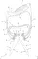
- FIG. 1 to 7 is a first embodiment of a pair of scissors 1 designed as articulated scissors with a first scissor blade 2, a second scissor blade 3, a first handle part 4 and a second handle part 5.
- the first scissor blade 2 and the second scissor blade 3 are connected to one another via a scissor joint 6 so that they can rotate about a geometric axis of rotation. Due to the scissor joint 6 and the common geometric axis of rotation, the two scissor blades 2, 3 are designed as two-armed scissor levers.
- Each scissor blade 2, 3 has a cutting arm 7, 8 and an actuating arm 9, 10.
- the axis of rotation for each of the two scissor blades 2, 3 is between the cutting arm 7, 8 and the actuating arm 9, 10.
- the actuating arm 9, 10 is angled relative to the cutting arm 7, 8.
- Each of the two cutting arms 7, 8 is equipped with a cutting edge 11, 12.
- the scissor blades 2, 3 are connected to one another via the scissor joint 6 in such a way that the two cutting edges 11, 12 face one another.
- the first handle part 4 is connected to the actuating arm 9 of the first scissor blade 2 and to the actuating arm 10 of the second scissor blade 3.
- the first handle part 4 and the two actuating arms 9, 10 form a first closed handle ring.
- the first handle part 4 has a finger rest 13.
- the index finger, middle finger, ring finger and little finger of a user's hand can be placed on the finger rest 13. They fit comfortably next to one another there.
- the finger, hand and user are not shown in the drawing.
- the second handle part 5 has a palm rest 14.
- the recess 15 is intended for the area of the thumb.
- the stop 16 prevents the hand placed on the palm rest 14 from slipping and thereby changing its position relative to the second handle part 5.
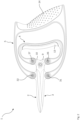
- the distance between the handle holder 17 and the axis of rotation 6 is smaller than the distance between the handle holder 17 and the tip 19 of the cutting arm 7.
- the position of the handle holder 17, 18 on the cutting arm 7, 8 is selected so that it limits the scissor blades 2, 3 when they move into the open position according to Figure 1 as little as possible and on the other hand the scissor joint 6 during the transition of the cutting arms 7, 8 into the closed position according to Figure 2 does not move too far towards the palm rest 14.
- the closed position of the scissors 1 shown shows how the position of the first and second scissor blades 2, 3, the first and second handle parts 4, 5 and the scissor joint changes when moving from the open position to the closed position.
- the two cutting arms 7, 8 are moved into the closed position by moving the finger rest 13 of the first handle part in the direction of the palm rest 14 of the second handle part. This takes the two actuating arms 9, 10 with them and rotates them about the geometric axis of rotation of the scissor joint 6. This movement is transferred to the cutting arms 7, 8.
- the second handle part 5 supports the two cutting arms 7, 8 laterally and stabilizes them.
- the first and second handle parts 4, 5 are made of plastic. They deform under the effect of the closing force of a hand when the hand pulls the first handle part 4 towards the second handle part 5. This deformation generates a restoring force. Due to this restoring force, the two scissor blades 2, 3 return with their cutting arms 7, 8 to the Figure 1 shown opening position as soon as the force of the hand is removed and the finger rest 13 is no longer actively pulled towards the palm rest 14.
- a pin 21 can be seen which is arranged on the first scissor blade 2.
- the second scissor blade 3 has an elongated through-opening 22 in which the pin 21 is guided.
- the pin 21 and the through-opening 22 limit the angle by which the first scissor blade 2 and the second scissor blade 3 can be rotated relative to one another.
- the first handle part 4 has a finger rest section 23 that includes the finger rest 13, a first handle part arm 24 and a second handle part arm 25.
- the two handle part arms are curved.
- the first handle part arm 24 is connected to the first scissor blade 2 on the first actuating arm 9 via a first handle part arm joint 26.
- the second handle part arm 25 is connected to the second scissor blade 3 on the second actuating arm 10 via a second handle part arm joint 27.
- the second handle part 4 has a palm section 28 that encompasses the palm rest 14, a first clamping arm 29 and a second clamping arm 30.
- the two clamping arms 29, 30 are curved.
- the first clamping arm 29 is connected to the second scissor blade 3 on the second handle holder 17 via a first clamping arm joint 31.
- the second clamping arm 30 is connected to the first scissor blade 2 on the first handle holder 17 via a second clamping arm joint 32.
- FIG 7 shows the scissors 1 according to the Figures 1 to 6 in the closed position, with a protective cap 33 placed on the two scissor blades 2, 3.
- This protective cap 33 covers the section of the scissor blades 2, 3 containing the cutting edges.
- the scissors 1 are held in the closed position by the protective cap 33.
- the protective cap 33 has two sections, each with a through opening. This through opening is pulled over the scissor joint 6, which projects outwards over the scissor blades 2, 3.
- the protective cap 33 is held on the scissors 1 by hanging the protective cap 33 on the scissor joint 6.
- FIG 8 a second embodiment of a pair of scissors 41 is shown. This is also a pair of articulated scissors.
- the scissors 41 have a small size. They are suitable for cosmetic purposes.
- the scissors 41 have a first scissor blade 42, a second scissor blade 43, a first handle part 44, a second handle part 45 and a scissor joint 46.
- the first scissor blade 42 and the second scissor blade 43 are rotatably connected to one another via the scissor joint 46.
- the first scissor blade 42 and the second scissor blade 43 are rounded at the tips to reduce the risk of injury.
- the two scissor blades 42, 43 are designed as two-armed scissor levers with a cutting arm 47, 48 and an actuating arm 49, 50.
- the cutting edges 51, 52 are located on the two cutting arms 47, 48.
- the first handle part 44 is attached to the actuating arms 49, 50.
- the second handle part 45 is connected to the cutting arms 47, 48 on the sides facing away from the cutting edges 51, 52.
- the first handle part 44 has a finger rest 53, while the second handle part 45 is equipped with a palm rest 54. In the area of the palm rest 54 there is an additional ring 55 into which the thumb can be inserted if necessary. The user can choose whether to place the palm of the hand on the palm rest 54 or to insert the thumb into the ring 55 to operate the scissors 41.
- the operation of the scissors 41 is similar to that of the scissors 1 according to the Figures 1 to 7 .
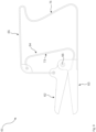
- a third embodiment of a pair of scissors 61 is shown, which is also designed as an articulated pair of scissors. It differs from the first embodiment of a pair of scissors 1 according to Figures 1 to 7 and from the second embodiment of a pair of scissors 41 according to Figure 8 in that the first handle part 64 is connected to the first scissor blade 62 and to the second handle part 65 and not to the second scissor blade 63.
- the second scissor blade 63 is only connected to the second handle part 65 and not to the first handle part 64.
- the two scissor blades 62, 63 are rotatably connected to one another via a scissor joint 66.
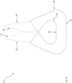
- FIG 10 A fourth embodiment of a pair of scissors 81 is shown.
- this is a pair of ironing scissors.
- the scissors 81 have a first blade 82, a second scissor blade 83, a first handle part 84 with a finger rest 93 and a second handle part 85 with a palm rest 94.
- the two scissor blades 82, 83 are not connected to one another via a scissor joint.
- the first handle part 84 is connected to the first scissor blade 82 at the end facing away from the tip and to the second scissor blade 83 at the end facing away from the tip.
- the second handle part 85 is connected to the first scissor blade 82 on the side facing away from the first cutting edge 91 and to the second scissor blade 83 on the side facing away from the second cutting edge 92.
- the finger rest 93 of the first handle part 84 is pulled towards the palm rest 94 of the second handle part, the two scissor blades 82, 83 are pivoted relative to one another in such a way that the cutting edges 91, 92 move towards one another and the scissor blades move into the closed position. In the process, an object placed between the scissor blades 82, 83 is cut.
Landscapes
- Life Sciences & Earth Sciences (AREA)
- Forests & Forestry (AREA)
- Engineering & Computer Science (AREA)
- Mechanical Engineering (AREA)
- Scissors And Nippers (AREA)
Applications Claiming Priority (1)
| Application Number | Priority Date | Filing Date | Title |
|---|---|---|---|
| DE102021121881.0A DE102021121881B3 (de) | 2021-08-24 | 2021-08-24 | Schere |
Publications (4)
| Publication Number | Publication Date |
|---|---|
| EP4151376A1 EP4151376A1 (de) | 2023-03-22 |
| EP4151376C0 EP4151376C0 (de) | 2024-05-01 |
| EP4151376B1 EP4151376B1 (de) | 2024-05-01 |
| EP4151376B9 true EP4151376B9 (de) | 2024-09-25 |
Family
ID=82786687
Family Applications (1)
| Application Number | Title | Priority Date | Filing Date |
|---|---|---|---|
| EP22188047.9A Active EP4151376B9 (de) | 2021-08-24 | 2022-08-01 | Schere |
Country Status (5)
| Country | Link |
|---|---|
| EP (1) | EP4151376B9 (pl) |
| DE (1) | DE102021121881B3 (pl) |
| ES (1) | ES2988409T3 (pl) |
| HU (1) | HUE067619T2 (pl) |
| PL (1) | PL4151376T3 (pl) |
Family Cites Families (7)
| Publication number | Priority date | Publication date | Assignee | Title |
|---|---|---|---|---|
| GB276160A (en) * | 1926-09-13 | 1927-08-25 | Sarah Emily Conrad | An improved cutting or shearing appliance |
| JPH0726915Y2 (ja) | 1990-10-25 | 1995-06-21 | アルスコーポレーション株式会社 | 摘果用カッター |
| US5279034A (en) * | 1992-12-01 | 1994-01-18 | The Caper Company | Scissors |
| US5290186A (en) * | 1993-01-04 | 1994-03-01 | John Juranitch | Poultry processing tool |
| US20080295341A1 (en) | 2007-06-04 | 2008-12-04 | Fiskars Brands, Inc. | Hand operated cutting tool |
| TWM350233U (en) | 2008-08-22 | 2009-02-11 | Natura Innovation Ltd | Gardening shear |
| JP5872126B2 (ja) * | 2013-11-08 | 2016-03-01 | 株式会社ヒカリ | 鋏 |
-
2021
- 2021-08-24 DE DE102021121881.0A patent/DE102021121881B3/de active Active
-
2022
- 2022-08-01 PL PL22188047.9T patent/PL4151376T3/pl unknown
- 2022-08-01 HU HUE22188047A patent/HUE067619T2/hu unknown
- 2022-08-01 ES ES22188047T patent/ES2988409T3/es active Active
- 2022-08-01 EP EP22188047.9A patent/EP4151376B9/de active Active
Also Published As
| Publication number | Publication date |
|---|---|
| PL4151376T3 (pl) | 2024-09-02 |
| EP4151376C0 (de) | 2024-05-01 |
| HUE067619T2 (hu) | 2024-11-28 |
| EP4151376A1 (de) | 2023-03-22 |
| EP4151376B1 (de) | 2024-05-01 |
| DE102021121881B3 (de) | 2022-11-10 |
| ES2988409T3 (es) | 2024-11-20 |
Similar Documents
| Publication | Publication Date | Title |
|---|---|---|
| EP0338243B1 (de) | Schere, insbesondere Friseurschere | |
| DE9001262U1 (de) | Chirurgischer Nadelhalter für eine Endo-Naht, Endo-Ligatur od.dgl. | |
| DE69600730T2 (de) | Instrument zum rausziehen von zecken aus der menschlichen oder tierischen haut | |
| DE9210327U1 (de) | Zangengriff für medizinische Gerätschaften | |
| EP0451487B1 (de) | Handgerät zum Schälen von länglichem Gemüse | |
| DE2032154A1 (de) | Fadenabschneider oder Clip | |
| EP1528971B1 (de) | Haarschneidemaschine | |
| DE102007024181B4 (de) | Stechvorrichtung für die Blutentnahme mit einer Schenkelfeder | |
| DE102010061055B4 (de) | Handgriffanordnung einer Schere | |
| WO2016192743A1 (de) | Werkzeuggriff und handgeführtes werkzeug mit einem derartigen werkzeuggriff | |
| EP4151376B9 (de) | Schere | |
| DE7918864U1 (de) | Werkzeughalter, vorzugsweise fuer zahntechnische zwecke | |
| EP0228659B1 (de) | Handschere für schwere Arbeiten | |
| DE2800796C3 (de) | Griff für Handgeräte | |
| EP1277550A1 (de) | Handschere | |
| DE2924830C2 (de) | Schere | |
| DE102023000156B3 (de) | Buchspreizer | |
| DE4322602A1 (de) | Zangengriff für medizinische Gerätschaften | |
| EP0413202B1 (de) | Feilenheft | |
| DE530540C (de) | Haarschneidemaschine | |
| DE102018112231A1 (de) | Klappwerkzeug | |
| DE19960439A1 (de) | Schere, insbesondere Friseurschere | |
| DE102014111840A1 (de) | Augenloser Instrumentenhandgriff für ein chirurgisches Rohrschaftinstrument | |
| DE2510688C2 (de) | Schere mit begrenzt drehbaren Griffaugen | |
| DE105662C (pl) |
Legal Events
| Date | Code | Title | Description |
|---|---|---|---|
| PUAI | Public reference made under article 153(3) epc to a published international application that has entered the european phase |
Free format text: ORIGINAL CODE: 0009012 |
|
| STAA | Information on the status of an ep patent application or granted ep patent |
Free format text: STATUS: THE APPLICATION HAS BEEN PUBLISHED |
|
| AK | Designated contracting states |
Kind code of ref document: A1 Designated state(s): AL AT BE BG CH CY CZ DE DK EE ES FI FR GB GR HR HU IE IS IT LI LT LU LV MC MK MT NL NO PL PT RO RS SE SI SK SM TR |
|
| STAA | Information on the status of an ep patent application or granted ep patent |
Free format text: STATUS: REQUEST FOR EXAMINATION WAS MADE |
|
| 17P | Request for examination filed |
Effective date: 20230405 |
|
| RBV | Designated contracting states (corrected) |
Designated state(s): AL AT BE BG CH CY CZ DE DK EE ES FI FR GB GR HR HU IE IS IT LI LT LU LV MC MK MT NL NO PL PT RO RS SE SI SK SM TR |
|
| RAP3 | Party data changed (applicant data changed or rights of an application transferred) |
Owner name: KEMPTER, LESLINE SOPHIE |
|
| RIN1 | Information on inventor provided before grant (corrected) |
Inventor name: KEMPTER, LESLINE SOPHIE |
|
| P01 | Opt-out of the competence of the unified patent court (upc) registered |
Effective date: 20230513 |
|
| STAA | Information on the status of an ep patent application or granted ep patent |
Free format text: STATUS: EXAMINATION IS IN PROGRESS |
|
| 17Q | First examination report despatched |
Effective date: 20230825 |
|
| GRAP | Despatch of communication of intention to grant a patent |
Free format text: ORIGINAL CODE: EPIDOSNIGR1 |
|
| STAA | Information on the status of an ep patent application or granted ep patent |
Free format text: STATUS: GRANT OF PATENT IS INTENDED |
|
| INTG | Intention to grant announced |
Effective date: 20240207 |
|
| GRAS | Grant fee paid |
Free format text: ORIGINAL CODE: EPIDOSNIGR3 |
|
| GRAA | (expected) grant |
Free format text: ORIGINAL CODE: 0009210 |
|
| STAA | Information on the status of an ep patent application or granted ep patent |
Free format text: STATUS: THE PATENT HAS BEEN GRANTED |
|
| AK | Designated contracting states |
Kind code of ref document: B1 Designated state(s): AL AT BE BG CH CY CZ DE DK EE ES FI FR GB GR HR HU IE IS IT LI LT LU LV MC MK MT NL NO PL PT RO RS SE SI SK SM TR |
|
| REG | Reference to a national code |
Ref country code: GB Ref legal event code: FG4D Free format text: NOT ENGLISH |
|
| REG | Reference to a national code |
Ref country code: CH Ref legal event code: EP |
|
| REG | Reference to a national code |
Ref country code: IE Ref legal event code: FG4D Free format text: LANGUAGE OF EP DOCUMENT: GERMAN |
|
| REG | Reference to a national code |
Ref country code: DE Ref legal event code: R096 Ref document number: 502022000835 Country of ref document: DE |
|
| P04 | Withdrawal of opt-out of the competence of the unified patent court (upc) registered |
Effective date: 20240522 |
|
| U01 | Request for unitary effect filed |
Effective date: 20240522 |
|
| U07 | Unitary effect registered |
Designated state(s): AT BE BG DE DK EE FI FR IT LT LU LV MT NL PT SE SI Effective date: 20240603 |
|
| REG | Reference to a national code |
Ref country code: RO Ref legal event code: EPE |
|
| GRAT | Correction requested after decision to grant or after decision to maintain patent in amended form |
Free format text: ORIGINAL CODE: EPIDOSNCDEC |
|
| REG | Reference to a national code |
Ref country code: CH Ref legal event code: PK Free format text: BERICHTIGUNG B9 |
|
| U20 | Renewal fee for the european patent with unitary effect paid |
Year of fee payment: 3 Effective date: 20240814 |
|
| PG25 | Lapsed in a contracting state [announced via postgrant information from national office to epo] |
Ref country code: IS Free format text: LAPSE BECAUSE OF FAILURE TO SUBMIT A TRANSLATION OF THE DESCRIPTION OR TO PAY THE FEE WITHIN THE PRESCRIBED TIME-LIMIT Effective date: 20240901 |
|
| PG25 | Lapsed in a contracting state [announced via postgrant information from national office to epo] |
Ref country code: HR Free format text: LAPSE BECAUSE OF FAILURE TO SUBMIT A TRANSLATION OF THE DESCRIPTION OR TO PAY THE FEE WITHIN THE PRESCRIBED TIME-LIMIT Effective date: 20240501 |
|
| PG25 | Lapsed in a contracting state [announced via postgrant information from national office to epo] |
Ref country code: GR Free format text: LAPSE BECAUSE OF FAILURE TO SUBMIT A TRANSLATION OF THE DESCRIPTION OR TO PAY THE FEE WITHIN THE PRESCRIBED TIME-LIMIT Effective date: 20240802 |
|
| PG25 | Lapsed in a contracting state [announced via postgrant information from national office to epo] |
Ref country code: IS Free format text: LAPSE BECAUSE OF FAILURE TO SUBMIT A TRANSLATION OF THE DESCRIPTION OR TO PAY THE FEE WITHIN THE PRESCRIBED TIME-LIMIT Effective date: 20240901 Ref country code: HR Free format text: LAPSE BECAUSE OF FAILURE TO SUBMIT A TRANSLATION OF THE DESCRIPTION OR TO PAY THE FEE WITHIN THE PRESCRIBED TIME-LIMIT Effective date: 20240501 Ref country code: GR Free format text: LAPSE BECAUSE OF FAILURE TO SUBMIT A TRANSLATION OF THE DESCRIPTION OR TO PAY THE FEE WITHIN THE PRESCRIBED TIME-LIMIT Effective date: 20240802 Ref country code: RS Free format text: LAPSE BECAUSE OF FAILURE TO SUBMIT A TRANSLATION OF THE DESCRIPTION OR TO PAY THE FEE WITHIN THE PRESCRIBED TIME-LIMIT Effective date: 20240801 |
|
| REG | Reference to a national code |
Ref country code: ES Ref legal event code: FG2A Ref document number: 2988409 Country of ref document: ES Kind code of ref document: T3 Effective date: 20241120 |
|
| REG | Reference to a national code |
Ref country code: HU Ref legal event code: AG4A Ref document number: E067619 Country of ref document: HU |
|
| PG25 | Lapsed in a contracting state [announced via postgrant information from national office to epo] |
Ref country code: CZ Free format text: LAPSE BECAUSE OF FAILURE TO SUBMIT A TRANSLATION OF THE DESCRIPTION OR TO PAY THE FEE WITHIN THE PRESCRIBED TIME-LIMIT Effective date: 20240501 |
|
| PG25 | Lapsed in a contracting state [announced via postgrant information from national office to epo] |
Ref country code: SK Free format text: LAPSE BECAUSE OF FAILURE TO SUBMIT A TRANSLATION OF THE DESCRIPTION OR TO PAY THE FEE WITHIN THE PRESCRIBED TIME-LIMIT Effective date: 20240501 |
|
| PG25 | Lapsed in a contracting state [announced via postgrant information from national office to epo] |
Ref country code: SM Free format text: LAPSE BECAUSE OF FAILURE TO SUBMIT A TRANSLATION OF THE DESCRIPTION OR TO PAY THE FEE WITHIN THE PRESCRIBED TIME-LIMIT Effective date: 20240501 |
|
| PG25 | Lapsed in a contracting state [announced via postgrant information from national office to epo] |
Ref country code: SM Free format text: LAPSE BECAUSE OF FAILURE TO SUBMIT A TRANSLATION OF THE DESCRIPTION OR TO PAY THE FEE WITHIN THE PRESCRIBED TIME-LIMIT Effective date: 20240501 Ref country code: SK Free format text: LAPSE BECAUSE OF FAILURE TO SUBMIT A TRANSLATION OF THE DESCRIPTION OR TO PAY THE FEE WITHIN THE PRESCRIBED TIME-LIMIT Effective date: 20240501 Ref country code: CZ Free format text: LAPSE BECAUSE OF FAILURE TO SUBMIT A TRANSLATION OF THE DESCRIPTION OR TO PAY THE FEE WITHIN THE PRESCRIBED TIME-LIMIT Effective date: 20240501 |
|
| REG | Reference to a national code |
Ref country code: DE Ref legal event code: R097 Ref document number: 502022000835 Country of ref document: DE |
|
| PLBE | No opposition filed within time limit |
Free format text: ORIGINAL CODE: 0009261 |
|
| STAA | Information on the status of an ep patent application or granted ep patent |
Free format text: STATUS: NO OPPOSITION FILED WITHIN TIME LIMIT |
|
| 26N | No opposition filed |
Effective date: 20250204 |
|
| PG25 | Lapsed in a contracting state [announced via postgrant information from national office to epo] |
Ref country code: RO Free format text: LAPSE BECAUSE OF NON-PAYMENT OF DUE FEES Effective date: 20240501 |
|
| PG25 | Lapsed in a contracting state [announced via postgrant information from national office to epo] |
Ref country code: MC Free format text: LAPSE BECAUSE OF FAILURE TO SUBMIT A TRANSLATION OF THE DESCRIPTION OR TO PAY THE FEE WITHIN THE PRESCRIBED TIME-LIMIT Effective date: 20240501 |
|
| PGFP | Annual fee paid to national office [announced via postgrant information from national office to epo] |
Ref country code: HU Payment date: 20250730 Year of fee payment: 4 |
|
| U20 | Renewal fee for the european patent with unitary effect paid |
Year of fee payment: 4 Effective date: 20250826 |
|
| PGFP | Annual fee paid to national office [announced via postgrant information from national office to epo] |
Ref country code: ES Payment date: 20250917 Year of fee payment: 4 |
|
| PGFP | Annual fee paid to national office [announced via postgrant information from national office to epo] |
Ref country code: NO Payment date: 20250820 Year of fee payment: 4 |
|
| PGFP | Annual fee paid to national office [announced via postgrant information from national office to epo] |
Ref country code: PL Payment date: 20250718 Year of fee payment: 4 Ref country code: TR Payment date: 20250729 Year of fee payment: 4 |
|
| PGFP | Annual fee paid to national office [announced via postgrant information from national office to epo] |
Ref country code: CH Payment date: 20250901 Year of fee payment: 4 |
|
| PGFP | Annual fee paid to national office [announced via postgrant information from national office to epo] |
Ref country code: IE Payment date: 20250821 Year of fee payment: 4 |
|
| PG25 | Lapsed in a contracting state [announced via postgrant information from national office to epo] |
Ref country code: CY Free format text: LAPSE BECAUSE OF FAILURE TO SUBMIT A TRANSLATION OF THE DESCRIPTION OR TO PAY THE FEE WITHIN THE PRESCRIBED TIME-LIMIT; INVALID AB INITIO Effective date: 20220801 |