EP4150304B1 - Verfahren zur bestimmung der schüttdichte von schüttgut in einem mobilen brecher - Google Patents
Verfahren zur bestimmung der schüttdichte von schüttgut in einem mobilen brecher Download PDFInfo
- Publication number
- EP4150304B1 EP4150304B1 EP21723108.3A EP21723108A EP4150304B1 EP 4150304 B1 EP4150304 B1 EP 4150304B1 EP 21723108 A EP21723108 A EP 21723108A EP 4150304 B1 EP4150304 B1 EP 4150304B1
- Authority
- EP
- European Patent Office
- Prior art keywords
- bulk material
- bulk
- determined
- conveyor belt
- weight
- Prior art date
- Legal status (The legal status is an assumption and is not a legal conclusion. Google has not performed a legal analysis and makes no representation as to the accuracy of the status listed.)
- Active
Links
Images

Classifications
-
- G—PHYSICS
- G01—MEASURING; TESTING
- G01F—MEASURING VOLUME, VOLUME FLOW, MASS FLOW OR LIQUID LEVEL; METERING BY VOLUME
- G01F13/00—Apparatus for measuring by volume and delivering fluids or fluent solid materials, not provided for in the preceding groups
- G01F13/001—Apparatus for measuring by volume and delivering fluids or fluent solid materials, not provided for in the preceding groups for fluent solid material
- G01F13/003—Apparatus for measuring by volume and delivering fluids or fluent solid materials, not provided for in the preceding groups for fluent solid material comprising a conveyor belt
-
- G—PHYSICS
- G01—MEASURING; TESTING
- G01G—WEIGHING
- G01G11/00—Apparatus for weighing a continuous stream of material during flow; Conveyor belt weighers
- G01G11/04—Apparatus for weighing a continuous stream of material during flow; Conveyor belt weighers having electrical weight-sensitive devices
-
- G—PHYSICS
- G01—MEASURING; TESTING
- G01N—INVESTIGATING OR ANALYSING MATERIALS BY DETERMINING THEIR CHEMICAL OR PHYSICAL PROPERTIES
- G01N9/00—Investigating density or specific gravity of materials; Analysing materials by determining density or specific gravity
- G01N9/02—Investigating density or specific gravity of materials; Analysing materials by determining density or specific gravity by measuring weight of a known volume
-
- G—PHYSICS
- G01—MEASURING; TESTING
- G01B—MEASURING LENGTH, THICKNESS OR SIMILAR LINEAR DIMENSIONS; MEASURING ANGLES; MEASURING AREAS; MEASURING IRREGULARITIES OF SURFACES OR CONTOURS
- G01B11/00—Measuring arrangements characterised by the use of optical techniques
- G01B11/24—Measuring arrangements characterised by the use of optical techniques for measuring contours or curvatures
-
- G—PHYSICS
- G01—MEASURING; TESTING
- G01G—WEIGHING
- G01G11/00—Apparatus for weighing a continuous stream of material during flow; Conveyor belt weighers
-
- G—PHYSICS
- G01—MEASURING; TESTING
- G01N—INVESTIGATING OR ANALYSING MATERIALS BY DETERMINING THEIR CHEMICAL OR PHYSICAL PROPERTIES
- G01N9/00—Investigating density or specific gravity of materials; Analysing materials by determining density or specific gravity
- G01N9/02—Investigating density or specific gravity of materials; Analysing materials by determining density or specific gravity by measuring weight of a known volume
- G01N2009/022—Investigating density or specific gravity of materials; Analysing materials by determining density or specific gravity by measuring weight of a known volume of solids
- G01N2009/024—Investigating density or specific gravity of materials; Analysing materials by determining density or specific gravity by measuring weight of a known volume of solids the volume being determined directly, e.g. by size of container
Definitions
- the invention relates to a method for determining the bulk density of bulk material in a mobile crusher, wherein the bulk material volume of bulk material fed onto a conveyor belt is determined according to claim 1.
- WO2017093609A1 discloses a method for determining the weight of bulk material on a conveyor belt using a scanning system that determines a three-dimensional profile of the bulk material.
- the volume of the bulk material is recorded from this three-dimensional profile and, together with a constant, previously known density of the bulk material, the weight is determined.
- the document WO 01/19165 A1 discloses a method for determining the moisture content of bulk material, in particular growth substrate such as potting soil, wherein the volume of a bulk material quantity is determined, the weight of the bulk material quantity is determined and then the specific density is determined from the volume and the weight.
- volume determination is also sensitive to environmental conditions, as the sensors are very sensitive to interference, such as dust or water drops. This makes it difficult to continuously determine the Conveying parameters such as the bulk material weight, bulk material volume, and derived quantities such as the conveying rate per hour.
- density of the bulk material must be known and constant in order to obtain reliable long-term measured values.
- the invention is therefore based on the object of being able to reliably determine the bulk material weight and bulk material volume over a longer operating period of a mobile crusher, even with varying bulk material density.
- the invention solves the problem by recording both the bulk material volume and the bulk material weight of a conveyor belt section in successive time steps and determining the bulk density from the quotient of the bulk material weight and the bulk material volume.
- the invention is based on the idea that the bulk material density of the bulk material fed in is known in normal operation. Nevertheless, the bulk material density is continuously determined during operation by determining the bulk material weight and the bulk material volume in parallel and is used as a control and correction value for the correct determination of the bulk material weight. If the measurement conditions change in such a way that either the determination of the bulk material weight or the bulk material volume is impaired, the bulk material density can either no longer be determined temporarily due to missing measurement data, or its value deviates from the known bulk density, whereby such an event can be recognized immediately.
- the bulk material volume can be determined, for example, using an optical scanning system and the bulk material weight can be determined, for example, using a power scale.
- the method can also be used if the reference value for the Bulk density can be used when an average bulk density is calculated from the bulk densities of previous time steps and an interference signal is output when a difference between the bulk density and the average bulk density is exceeded. It is assumed that the determination of bulk material volume and bulk material weight was carried out correctly a predetermined number of time steps before the interference signal was output, and an average bulk density can be calculated from the bulk densities determined at these time steps, which is used for the test.
- This provides a reference value for the bulk density that is continuously adjusted during operation, so that the difference required to output an interference signal can be kept small.
- This interference signal can be transmitted to the user, for example via a wireless network.
- reference runs with measured bulk material can be carried out before actual operation, for example.
- a change in the operating temperature or location of the crusher or bulk material jammed on the conveyor belt can impair the comparability of the measurement data or lead to measurement errors.
- Incorrect determination of the bulk material weight can, however, be corrected when the interference signal is output in this case by determining at least one measurement state variable of the conveyor belt for each time step and, in the case of an interference signal, a corrected bulk material weight is determined from the bulk material volume and the bulk density mean value in the case of an interference signal when the measurement state variable of the conveyor belt differs from the last time steps.
- Measurement state variables are those variables that can influence the determination of the bulk material weight, such as inclination and speed, operating temperature, orientation or location of the conveyor belt as well as the plausibility of the measurement signals.
- a change in inclination and/or a change in the speed of the conveyor belt due to a change in location changes the vertically acting force component, so that a lower bulk material weight is measured for the same mass. If the operating temperature, orientation or location changes, the complex mechanics of the conveyor belt can lead to can also lead to changed measurement conditions. A change in location can be easily determined, for example, by using the operation of the undercarriage as the measurement state variable.
- the measurement signals for the bulk material weight can be checked for plausibility and in this way, for example, transmission or other system errors in the determination of the bulk material weight can be determined. If an interference signal is output, the product of the mean bulk density and the bulk material volume can be used as the corrected bulk material weight.
- a correction term be determined from the bulk material weight before the interference signal is output and the bulk material weight after the interference signal is output and that this is applied to the bulk material weights after the interference signal is output.
- the bulk material weight before the interference signal is output and the bulk material weight after the interference signal is output can be obtained by forming the mean value of bulk material weights from several time steps.
- an incorrect determination of the bulk material volume when the interference signal is output can be easily corrected by determining at least one measurement state variable of the conveyor belt for each time step and, in the case of an interference signal, a corrected bulk material volume is determined from the bulk material weight and the bulk density mean value when the measurement state variable of the conveyor belt is the same as in the last time steps.
- the measurement state variables that can influence the determination of the bulk material weight can be used as the measurement state variables described above. Because the measurement of the bulk material volume is more susceptible to interference than the measurement of the bulk material weight due to the dust that occurs during operation, it can be assumed that the change in the bulk density results from incorrect measurements of the bulk material volume if no change in the measurement state variable occurs. When an interference signal is output, the quotient can be from the bulk material weight and the bulk density mean value as the corrected bulk material volume.
- Meaningful measured values can be determined over the long term by recording the bulk material volume and the bulk material weight for each time step and by determining the corrected bulk material volume as the bulk material volume and/or the corrected bulk material weight as the bulk material weight for the time steps in which an interference signal was output. In this way, a bulk material weight, a bulk material volume and a bulk density are recorded for each time step, even when an interference signal is output. From these measured values, other relevant parameters can then be reliably determined, such as the energy consumption of a crusher per ton of bulk material processed. In a particularly preferred embodiment of the method according to the invention, the corrected measurement results are marked so that the corrected measured values can be distinguished from the original, incorrect measured values.
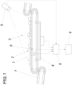
- a device for carrying out the method according to the invention comprises a conveyor belt 1 which transports bulk material 2.
- the bulk material 2 of a conveyor belt section 3 is measured by a scale 4 and an optical scanning system 5, whereby the scale 4 determines the weight of the bulk material on the conveyor belt section 3 and forwards it to a computing unit 6.
- the scale 4 can be, for example, a roller chair belt scale or in a In a particularly preferred embodiment, a current-power scale is used.
- the optical scanning system 5 measures the bulk material 2 and also sends the measurement data to the computing unit 6, which determines the volume of the bulk material 2 from the measurement data.
- sensors for determining the measurement state variables such as an inclination sensor 7 and a speed sensor 8, which transmit the inclination and speed of the conveyor belt to the computing unit 6.
- sensors can be present for determining other measurement state variables, such as the operating temperature and the position of the crusher. These can also be housed in the housing of the inclination sensor 7, for example.
- the computing unit 6 is equipped with an interference signal transmitter 9, which informs a user about changes in the measurement conditions.
- the bulk material weight, bulk material volume and bulk density are determined from the measured data, whereby first the maximum permissible difference between bulk density and mean bulk density and the maximum permissible change in the measured state variables on the conveyor belt 1 are stored in the computing unit 6.
- step 10 the bulk material weight, the determined bulk material volume and the measured state variables of the conveyor belt section 3 are read in for each time period, and the bulk density is determined from the bulk material weight and bulk material volume.
- step 10 the bulk density mean is calculated from a predetermined number of bulk densities from past time steps.
- step 11 it is checked whether the maximum permissible difference between bulk density and mean bulk density is exceeded.
- step 12 follows, in which the measured bulk material weight, bulk material volume and the resulting bulk density are stored for this time step.
- step 13 follows, in which a fault signal is output.
- step 14 it is then determined whether the maximum permissible change in the measured state variable of the conveyor belt has been exceeded.
- step 15 follows, in which it is assumed that the optical scanning system 5 has delivered incorrect values for this time step and the scale 4 delivers reliable values.
- the measured bulk material weight is therefore saved for this time step.
- the bulk material volume is determined as the quotient of the bulk material weight and the bulk density mean value determined in step 10 and saved for this time step. For this time step, the last valid bulk density or the bulk density mean value can be saved as the bulk density.
- step 16 follows, in which it is assumed that the scale 4 has delivered incorrect values due to the change in the measurement state variable on the conveyor belt section 3 and that the optical scanning system 5 delivers reliable values.
- the measured bulk material volume is therefore saved for this time step.
- the bulk material weight is determined as the product of the bulk material volume and the mean bulk density determined in step 10 and saved for this time step. For this time step, the last valid bulk density or the mean bulk density can be saved as the bulk density.
Landscapes
- Physics & Mathematics (AREA)
- General Physics & Mathematics (AREA)
- Analytical Chemistry (AREA)
- Health & Medical Sciences (AREA)
- Life Sciences & Earth Sciences (AREA)
- Chemical & Material Sciences (AREA)
- Biochemistry (AREA)
- General Health & Medical Sciences (AREA)
- Immunology (AREA)
- Pathology (AREA)
- Fluid Mechanics (AREA)
- Control Of Conveyors (AREA)
- Engineering & Computer Science (AREA)
- Food Science & Technology (AREA)
Description
- Die Erfindung bezieht sich auf ein Verfahren zur Bestimmung der Schüttdichte von Schüttgut in einem mobilen Brecher wobei das Schüttgutvolumen von auf ein Förderband aufgegebenem Schüttgut bestimmt wird nach Anspruch 1.
- Aus dem Stand der Technik sind viele Methoden bekannt, das Gewicht von Schüttgut auf einem Förderband entweder direkt über Waagen, oder indirekt aus dem Schüttgutvolumen zu messen. Die Anwendung üblicher Bandwaagen zur direkten Messung des Gewichtes ist allerdings bei mobilem Einsatz schwierig, da sich die Betriebstemperatur, Neigung des Förderbandes, Viskosität des Schmiermittels, etc. aufgrund der Umweltbedingungen oft ändert, wodurch solche Systeme häufig kalibriert werden müssen. Allerdings ist die Bestimmung des Gewichtes auch über das Volumen möglich. Die
WO2017093609A1 offenbart ein Verfahren zur Bestimmung des Schüttgutgewichtes auf einem Förderband mithilfe eines Abtastsystems, welches ein dreidimensionales Profil des Schüttgutes ermittelt. Aus diesem dreidimensionalen Profil wird das Volumen des Schüttgutes erfasst und zusammen mit einer konstanten, vorher bekannten Dichte des Schüttgutes das Gewicht bestimmt. Das DokumentWO 01/19165 A1 - Nachteilig am Stand der Technik ist allerdings, dass auch die Volumenbestimmung empfindlich gegenüber Umweltbedingungen ist, da die Sensoren sehr sensibel bezüglich Störeinflüssen, wie beispielsweise Staub oder Wassertropfen, sind. Dies erschwert das kontinuierliche Ermitteln der Förderparameter wie dem Schüttgutgewicht, Schüttgutvolumen, sowie daraus abgeleiteter Größen wie beispielsweise der Fördermenge pro Stunde. Darüber hinaus muss die Dichte des Schüttgutes bekannt und konstant sein, um langfristig zuverlässige Messwerte zu erhalten.
- Der Erfindung liegt somit die Aufgabe zugrunde, über eine längere Betriebsdauer eines mobilen Brechers auch bei variierender Schüttgutdichte zuverlässig Schüttgutgewicht und Schüttgutvolumen bestimmen zu können.
- Die Erfindung löst die gestellte Aufgabe dadurch, dass in aufeinanderfolgenden Zeitschritten sowohl das Schüttgutvolumen als auch das Schüttgutgewicht eines Förderbandabschnittes erfasst und aus dem Quotienten des Schüttgutgewichtes und des Schüttgutvolumens die Schüttdichte bestimmt wird. Der Erfindung liegt dabei die Überlegung zugrunde, dass die Schüttgutdichte des aufgegebenen Schüttgutes im Normalbetrieb bekannt ist. Dennoch wird die Schüttgutdichte über die parallele Ermittlung des Schüttgutgewichts und des Schüttgutvolumens laufend während des Betriebs bestimmt und als Kontroll- und Korrekturwert für die ordnungsgemäße Bestimmung des Schüttgutgewichtes eingesetzt. Ändern sich also die Messbedingungen dergestalt, dass entweder die Ermittlung des Schüttgutgewichtes oder des Schüttgutvolumens beeinträchtigt ist, kann die Schüttgutdichte entweder aufgrund fehlender Messdaten temporär nicht mehr bestimmt werden, oder ihr Wert weicht von der bekannten Schüttdichte ab, wodurch ein solches Ereignis sofort erkannt werden kann. Die Erfassung des Schüttgutvolumens kann beispielsweise mit einem optischen Abtastsystem bestimmt werden und das Schüttgutgewicht kann beispielsweise mit einer Leistungswaage erfolgen.
- Sollte die Schüttdichte des Schüttgutes nicht exakt bekannt sein, lässt sich unter Umständen nicht ermitteln, ob und welche Messwerte fehlerhaft sind, da kein Referenzwert zur Beurteilung der gemessenen Gewichte und Volumina vorliegt. Das Verfahren kann allerdings auch bei unbekanntem Referenzwert für die Schüttdichte verwendet werden, wenn aus den Schüttdichten vorangegangener Zeitschritte ein Schüttdichtenmittelwert gebildet wird und beim Überschreiten eines Differenzbetrags zwischen Schüttdichte und Schüttdichtenmittelwert ein Störsignal ausgegeben wird. Dabei wird davon ausgegangen, dass die Bestimmung von Schüttgutvolumen und Schüttgutgewicht eine vorgegebene Anzahl von Zeitschritten vor Ausgabe des Störsignals ordnungsgemäß erfolgte, kann aus den zu diesen Zeitschritten bestimmten Schüttdichten ein Schüttdichtenmittelwert gebildet werden, der für die Prüfung herangezogen wird. Damit steht ein laufend während des Betriebs angepasster Referenzwert für die Schüttdichte zur Verfügung, sodass der für die Ausgabe eines Störsignals erforderliche Differenzbetrag klein gehalten werden kann. Dieses Störsignal kann, beispielsweise über ein Drahtlosnetzwerk, an den Benutzer übermittelt werden. Um zu überprüfen, ob die Gewichts- und die Volumenbestimmung ordnungsgemäß funktionieren, können beispielsweise vor dem eigentlichen Betrieb Referenzfahrten mit vermessenem Schüttgut durchgeführt werden.
- Beispielsweise kann eine Betriebstemperatur - oder Standortänderung des Brechers oder am Förderband verklemmtes Schüttgut die Vergleichbarkeit der Messdaten verschlechtern oder zu Messfehlern führen. Ein fehlerhaftes Ermitteln des Schüttgutgewichts kann bei Ausgabe des Störsignals in diesem Fall jedoch korrigiert werden, indem für jeden Zeitschritt wenigstens eine Messzustandsgröße des Förderbandes ermittelt und im Falle eines Störsignals bei gegenüber den letzten Zeitschritten abweichender Messzustandsgröße des Förderbandes aus dem Schüttgutvolumen und dem Schüttdichtenmittelwert ein korrigiertes Schüttgutgewicht bestimmt wird. Messzustandsgrößen sind diejenigen Größen, die die Bestimmung des Schüttgutgewichtes beeinflussen können, wie beispielsweise Neigung und Geschwindigkeit, Betriebstemperatur, Orientierung oder Standort des Förderbandes sowie die Plausibilität der Messsignale. Durch eine standortswechselbedingte Änderung der Neigung und/oder einer Änderung der Geschwindigkeit des Förderbandes ändert sich nämlich die vertikal wirkende Kraftkomponente, sodass bei gleicher Masse ein geringeres Schüttgutgewicht gemessen wird. Bei einer Änderung der Betriebstemperatur, Orientierung oder des Standortes kann es aufgrund der komplexen Mechanik des Förderbandes ebenfalls zu geänderten Messbedingungen kommen. Eine Veränderung des Standortes kann in einfacher Weise beispielsweise dadurch festgestellt werden, indem die Betätigung des Fahrwerks als Messzustandsgröße verwendet wird. Darüber hinaus können die Messsignale für das Schüttgutgewicht auf ihre Plausibilität hin geprüft werden und auf diese Weise beispielsweise Übertragungs- oder andere Systemfehler bei der Bestimmung des Schüttgutgewichts ermittelt werden. Bei Ausgabe eines Störsignals kann das Produkt aus dem Schüttdichtenmittelwert und dem Schüttgutvolumen als korrigiertes Schüttgutgewicht herangezogen werden. Um nach einer Änderung einer Messzustandsgröße des Förderbandes das gemessene Schüttgutgewicht weiterhin heranziehen zu können, wird vorgeschlagen, dass aus dem Schüttgutgewicht vor Ausgabe des Störsignals und dem Schüttgutgewicht nach Ausgabe des Störsignals ein Korrekturterm bestimmt und auf die Schüttgutgewichte nach Ausgabe des Störsignals angewendet wird. Zur exakteren Ermittlung des Korrekturterms kann das Schüttgutgewicht vor Ausgabe des Störsignals und das Schüttgutgewicht nach Ausgabe des Störsignals durch Bildung des Mittelwerts aus Schüttgutgewichten mehrerer Zeitschritte gewonnen werden.
- Analog dazu kann ein fehlerhaftes Ermitteln des Schüttgutvolumens bei Ausgabe des Störsignales einfach korrigiert werden, indem für jeden Zeitschritt wenigstens eine Messzustandsgröße des Förderbandes ermittelt und im Falle eines Störsignals bei gegenüber den letzten Zeitschritten gleichbleibender Messzustandsgröße des Förderbandes aus dem Schüttgutgewicht und dem Schüttdichtenmittelwert ein korrigiertes Schüttgutvolumen bestimmt wird. Als Messzustandsgrößen können die oben beschriebenen herangezogen werden, die die Bestimmung des Schüttgutgewichts beeinflussen können. Dadurch, dass die Messung des Schüttgutvolumens aufgrund der auftretenden Staubentwicklung im Betrieb störanfälliger als die Messung des Schüttgutgewichts ist, kann für den Fall, dass keine Änderung der Messzustandsgröße auftritt, davon ausgegangen werden, dass die Änderung der Schüttdichte aus fehlerhaften Messungen des Schüttgutvolumens resultiert. Bei Ausgabe eines Störsignals kann der Quotient aus dem Schüttgutgewicht und dem Schüttdichtenmittelwert als korrigiertes Schüttgutvolumen herangezogen werden.
- Aussagekräftige Messwerte lassen sich langfristig ermitteln, indem je Zeitschritt das Schüttgutvolumen und das Schüttgutgewicht aufgezeichnet wird und dass für die Zeitschritte, bei denen ein Störsignal ausgegeben wurde, das korrigierte Schüttgutvolumen als Schüttgutvolumen und/oder das korrigierte Schüttgutgewicht als Schüttgutgewicht ermittelt wird. So wird für jeden Zeitschritt, auch bei Ausgabe eines Störsignals, ein Schüttgutgewicht, ein Schüttgutvolumen und eine Schüttdichte aufgezeichnet. Aus diesen Messwerten lassen sich in weiterer Folge zuverlässig weitere relevante Parameter, wie beispielsweise der Energieverbrauch eines Brechers pro verarbeiteter Tonne Schüttgut ermitteln. In einer besonders bevorzugten Ausführungsform des erfindungsgemäßen Verfahrens werden die korrigierten Messergebnisse markiert, sodass sich die korrigierten Messwerte von den ursprünglichen, fehlerhaften Messwerten unterscheiden lassen.
- In der Zeichnung ist der Erfindungsgegenstand beispielsweise dargestellt. Es zeigen
- Fig. 1
- eine schematische Seitenansicht einer Vorrichtung zur erfindungsgemäßen Durchführung des Verfahrens und
- Fig. 2
- ein Flussdiagramm eines Teils des erfindungsgemäßen Verfahrens.
- Eine Vorrichtung zur erfindungsgemäßen Durchführung des Verfahrens umfasst ein Förderband 1, welches Schüttgut 2 transportiert. Das Schüttgut 2 eines Förderbandabschnittes 3 wird dabei von einer Waage 4 und einem optischen Abtastsystem 5 vermessen, wobei die Waage 4 das Schüttgutgewicht auf dem Förderbandabschnitt 3 bestimmt und an eine Recheneinheit 6 weiterleitet. Als Waage 4 kann beispielsweise eine Rollenstuhlbandwaage oder in einer besonders bevorzugten Ausführungsform eine Strom-Leistungswaage zum Einsatz kommen. Das optische Abtastsystem 5 vermisst das Schüttgut 2, und sendet die Messdaten ebenfalls an die Recheneinheit 6, die das Volumen des Schüttgutes 2 aus den Messdaten bestimmt. Auf dem Förderband 1 befindet sich zusätzlich Sensoren zur Ermittlung der Messzustandsgrößen, wie beispielweise ein Neigungssensor 7 und ein Geschwindigkeitssensor 8, die Neigung und Geschwindigkeit des Förderbands an die Recheneinheit 6 übermitteln. Zusätzlich können noch Sensoren zur Bestimmung anderer Messzustandsgrößen, wie beispielsweise der Betriebstemperatur und der Lage des Brechers vorhanden sein. Diese können beispielsweise ebenfalls im Gehäuse des Neigungssensors 7 untergebracht sein. Die Recheneinheit 6 ist mit einem Störsignalsender 9 ausgestattet, welches einem Benutzer über Änderungen der Messbedingungen informiert.
- Mittels der Recheneinheit 6 wird aus den gemessenen Daten Schüttgutgewicht, Schüttgutvolumen und Schüttdichte bestimmt, wobei zuerst der maximal zulässige Differenzbetrag zwischen Schüttdichte und Schüttdichtenmittelwert und die maximal zulässige Änderung der Messzustandsgrößen am Förderband 1 in der Recheneinheit 6 abgelegt werden.
- Wie insbesondere der
Figur 2 entnommen werden kann, wird zuerst in Schritt 10 für jeden Zeitabschnitt das Schüttgutgewicht, das bestimmte Schüttgutvolumen, sowie die Messzustandsgrößen des Förderbandabschnittes 3 eingelesen, sowie aus Schüttgutgewicht und Schüttgutvolumen die Schüttdichte ermittelt. Zusätzlich wird in diesem Schritt der Schüttdichtenmittelwert aus einer vorgegebenen Anzahl von Schüttdichten vergangener Zeitschritte gebildet. - In Schritt 11 wird überprüft, ob der maximal zulässige Differenzbetrag zwischen Schüttdichte und Schüttdichtenmittelwert überschritten wird.
- Ist dies nicht der Fall, folgt Schritt 12, in dem das gemessene Schüttgutgewicht, Schüttgutvolumen und die daraus ermittelte Schüttdichte für diesen Zeitschritt gespeichert werden.
- Wird allerdings der maximal zulässige Differenzbetrag zwischen Schüttdichte und Schüttdichtenmittelwert überschritten, folgt Schritt 13, in dem ein Störsignal ausgegeben wird. In Schritt 14 wird anschließend bestimmt, ob die maximal zulässige Änderung der Messzustandsgröße des Förderbandes überschritten wurde.
- Ist dies nicht der Fall, folgt Schritt 15, in dem davon ausgegangen wird, dass das optische Abtastsystem 5 für diesen Zeitschritt falsche Werte geliefert hat und die Waage 4 zuverlässige Werte liefert. Das gemessene Schüttgutgewicht wird deshalb für diesen Zeitschritt gespeichert. Das Schüttgutvolumen wird als Quotient des Schüttgutgewichtes und dem in Schritt 10 ermittelten Schüttdichtenmittelwert bestimmt und für diesen Zeitschritt gespeichert. Für diesen Zeitschritt kann die zuletzt gültige Schüttdichte oder der Schüttdichtenmittelwert als Schüttdichte gespeichert werden.
- Wird die maximal zulässige Änderung der Messzustandsgröße des Förderbandes überschritten, folgt Schritt 16, in dem davon ausgegangen wird, dass die Waage 4 durch die Änderung der Messzustandsgröße am Förderbandabschnitt 3 falsche Werte geliefert hat und das optische Abtastsystem 5 zuverlässige Werte liefert. Das gemessene Schüttgutvolumen wird deshalb für diesen Zeitschritt gespeichert. Das Schüttgutgewicht wird als Produkt des Schüttgutvolumens und dem in Schritt 10 ermittelten Schüttdichtenmittelwert bestimmt und für diesen Zeitschritt gespeichert. Für diesen Zeitschritt kann die zuletzt gültige Schüttdichte oder der Schüttdichtenmittelwert als Schüttdichte gespeichert werden.
Claims (5)
- Verfahren zur Bestimmung der Schüttdichte von Schüttgut (2) in einem mobilen Brecher wobei das Schüttgutvolumen von auf ein Förderband (1) aufgegebenem Schüttgut (2) bestimmt wird, dadurch gekennzeichnet, dass in aufeinanderfolgenden Zeitschritten sowohl das Schüttgutvolumen als auch das Schüttgutgewicht eines Förderbandabschnittes (3) erfasst und aus dem Quotienten des Schüttgutgewichtes und des Schüttgutvolumens die Schüttdichte bestimmt wird.
- Verfahren nach Anspruch 1, dadurch gekennzeichnet, dass aus den Schüttdichten vorangegangener Zeitschritte ein Schüttdichtenmittelwert gebildet wird und dass beim Überschreiten eines Differenzbetrags zwischen Schüttdichte und Schüttdichtenmittelwert ein Störsignal ausgegeben wird.
- Verfahren nach Anspruch 2, dadurch gekennzeichnet, dass für jeden Zeitschritt wenigstens eine Messzustandsgröße des Förderbandes (1) ermittelt und im Falle eines Störsignals bei gegenüber den letzten Zeitschritten abweichender Messzustandsgröße des Förderbandes (1) aus dem Schüttgutvolumen und dem Schüttdichtenmittelwert ein korrigiertes Schüttgutgewicht bestimmt wird.
- Verfahren nach Anspruch 2 oder 3, dadurch gekennzeichnet, dass für jeden Zeitschritt wenigstens eine Messzustandsgröße des Förderbandes (1) ermittelt und im Falle eines Störsignals bei gegenüber den letzten Zeitschritten gleichbleibende Messzustandsgröße des Förderbandes (1) aus dem Schüttgutgewicht und dem Schüttdichtenmittelwert ein korrigiertes Schüttgutvolumen bestimmt wird.
- Verfahren nach einem der Ansprüche 3 oder 4, dadurch gekennzeichnet, dass je Zeitschritt das Schüttgutvolumen und das Schüttgutgewicht aufgezeichnet wird und dass für die Zeitschritte, bei denen ein Störsignal ausgegeben wurde, das korrigierte Schüttgutvolumen als Schüttgutvolumen und/oder das korrigierte Schüttgutgewicht als Schüttgutgewicht ermittelt wird.
Applications Claiming Priority (2)
| Application Number | Priority Date | Filing Date | Title |
|---|---|---|---|
| ATA50424/2020A AT523414B1 (de) | 2020-05-13 | 2020-05-13 | Verfahren zur Bestimmung der Schüttdichte von Schüttgut in einem mobilen Brecher |
| PCT/AT2021/060141 WO2021226644A1 (de) | 2020-05-13 | 2021-04-26 | Verfahren zur bestimmung der schüttdichte von schüttgut in einem mobilen brecher |
Publications (3)
| Publication Number | Publication Date |
|---|---|
| EP4150304A1 EP4150304A1 (de) | 2023-03-22 |
| EP4150304B1 true EP4150304B1 (de) | 2024-10-09 |
| EP4150304C0 EP4150304C0 (de) | 2024-10-09 |
Family
ID=75786859
Family Applications (1)
| Application Number | Title | Priority Date | Filing Date |
|---|---|---|---|
| EP21723108.3A Active EP4150304B1 (de) | 2020-05-13 | 2021-04-26 | Verfahren zur bestimmung der schüttdichte von schüttgut in einem mobilen brecher |
Country Status (5)
| Country | Link |
|---|---|
| US (1) | US20230078898A1 (de) |
| EP (1) | EP4150304B1 (de) |
| CN (1) | CN115176131A (de) |
| AT (1) | AT523414B1 (de) |
| WO (1) | WO2021226644A1 (de) |
Families Citing this family (1)
| Publication number | Priority date | Publication date | Assignee | Title |
|---|---|---|---|---|
| CN117342223B (zh) * | 2023-12-04 | 2024-02-20 | 泰州润辰新材料有限公司 | 一种绝缘粉末涂料加工用定量进料装置 |
Family Cites Families (18)
| Publication number | Priority date | Publication date | Assignee | Title |
|---|---|---|---|---|
| US4487278A (en) * | 1983-08-24 | 1984-12-11 | Trebor Industries, Inc. | Instrument for providing automatic measurement of test weight |
| DE3933424C1 (de) * | 1989-10-06 | 1991-04-18 | Carl Schenck Ag, 6100 Darmstadt, De | |
| DE4135329C2 (de) * | 1991-10-25 | 1996-05-09 | Kromer Karl Hans Prof Dr Ing | Waagengebundenes Meßverfahren zur Bestimmung des Erdmasse-Anteiles in Haufwerken landwirtschaftlicher Güter, speziell in Zuckerrüben |
| DE4200770A1 (de) * | 1992-01-14 | 1993-07-15 | Bat Cigarettenfab Gmbh | Verfahren und vorrichtung zur ermittlung der fuellfaehigkeit von tabakmaterial mittels laserabtastung |
| DE19731603C2 (de) * | 1997-07-18 | 1999-11-11 | Anatec Gmbh | Verfahren zum Wiegen auf bandförmigen Fördereinrichtungen und dergleichen Einrichtungen und Waage für bandförmige Fördereinrichtung |
| DE19808148A1 (de) * | 1998-02-27 | 1999-09-02 | Kromer | Bestimmung des Erdanteils in Förderströmen landwirtschaftlicher Güter |
| NL1013057C2 (nl) * | 1999-09-15 | 2001-03-16 | Visser S Gravendeel Holding | Inrichting en werkwijze voor het meten van de vochtigheidsgraad van teeltsubstraat zoals potgrond. |
| DE102008017671B4 (de) * | 2008-04-08 | 2020-09-10 | Deere & Company | Messanordnung zur Massendurchsatzerfassung mit Massen- und Volumenmessung und darauf basierender Massendichtenbestimmung sowie Massendurchsatzangabe bei kleinen Durchsätzen anhand der zuletzt erfassten Massendichte |
| US9766107B2 (en) * | 2010-12-15 | 2017-09-19 | Anubis Manufacturing Consultants Corp. | System for and method of measuring flow of bulk solid material |
| DE102012209495B4 (de) * | 2011-06-09 | 2014-07-24 | Alfred Ulrich | Straßenfertiger und Verfahren zu seiner Verwendung |
| US10300830B2 (en) * | 2011-10-24 | 2019-05-28 | Solaris Oilfield Site Services Operating Llc | Storage and blending system for multi-component granular compositions |
| CN103837222B (zh) * | 2014-03-12 | 2015-11-18 | 北京工业职业技术学院 | 皮带秤图像校验方法和计量监测系统 |
| FI126947B (en) | 2015-12-01 | 2017-08-31 | Outotec Finland Oy | Method and arrangement for determining the ore mass flow rate of ore transported in the comminution process |
| CN108267201A (zh) * | 2016-12-30 | 2018-07-10 | 上海云统信息科技有限公司 | 一种皮带输运散料的计量方法 |
| CN108264201B (zh) * | 2018-03-28 | 2020-07-21 | 北京交通大学 | 一种同步脱氮除磷的低c/n污水处理工艺方法 |
| CN108801878A (zh) * | 2018-07-10 | 2018-11-13 | 华侨大学 | 一种确定堆积散粒状物料空隙率的方法 |
| WO2020049513A2 (de) * | 2018-09-07 | 2020-03-12 | K-Tron Technologies, Inc. | Verfahren zur gravimetrischen regelung eines dosierers für schüttgut während der nachfüllung seines vorratsbehälters und dosierer zur ausführung des verfahrens |
| CN110514553B (zh) * | 2019-09-24 | 2021-10-22 | 中国烟草总公司郑州烟草研究院 | 一种输送带上烟丝物料堆积密度的在线检测方法 |
-
2020
- 2020-05-13 AT ATA50424/2020A patent/AT523414B1/de active
-
2021
- 2021-04-26 WO PCT/AT2021/060141 patent/WO2021226644A1/de not_active Ceased
- 2021-04-26 EP EP21723108.3A patent/EP4150304B1/de active Active
- 2021-04-26 CN CN202180009167.2A patent/CN115176131A/zh active Pending
- 2021-04-26 US US17/785,800 patent/US20230078898A1/en not_active Abandoned
Also Published As
| Publication number | Publication date |
|---|---|
| US20230078898A1 (en) | 2023-03-16 |
| EP4150304C0 (de) | 2024-10-09 |
| AT523414A4 (de) | 2021-08-15 |
| AT523414B1 (de) | 2021-08-15 |
| CN115176131A (zh) | 2022-10-11 |
| EP4150304A1 (de) | 2023-03-22 |
| WO2021226644A1 (de) | 2021-11-18 |
Similar Documents
| Publication | Publication Date | Title |
|---|---|---|
| EP2246673B1 (de) | Verfahren zum Bestimmen des Volumens von Fördergut und Vorrichtung | |
| EP2278283A1 (de) | Verfahren zur Temperaturkorrektur einer Kraftmessvorrichtung und Kraftmessvorrichtung | |
| EP2057883B1 (de) | Landwirtschaftliche Arbeitsmaschine | |
| EP0354218B1 (de) | verfahren für die eichung und den betrieb einer waage | |
| DE1773462A1 (de) | Verfahren und Vorrichtung zur schnellen und kontinuierlichen Bestimmung der Eigenschaften metallischer Werkstoffe | |
| EP0511217B1 (de) | Kompensationswaage | |
| EP4150304B1 (de) | Verfahren zur bestimmung der schüttdichte von schüttgut in einem mobilen brecher | |
| EP1736746B1 (de) | Verfahren zur Optimierung des Verhaltens einer Kraftmessvorrichtung sowie eine Kraftmessvorrichtung zur Durchführung des Verfahrens. | |
| DE102007058102A1 (de) | Sensornetzwerk für ein Luftfahrzeug | |
| WO1996007876A1 (de) | Wägevorrichtung | |
| EP1921428A1 (de) | Verfahren zur Überwachung und/oder Bestimmung des Zustandes einer Kraftmessvorrichtung und Kraftmessvorrichtung | |
| DE102016201784A1 (de) | Sensorsystem zum Erfassen mindestens einer Betätigungsgröße eines Pedals | |
| DE3719532A1 (de) | Kraftmesseinrichtung | |
| DE3414247A1 (de) | Verfahren und vorrichtung zum messen des durchmessers von strang- oder stabfoermigen erzeugnissen der tabakverarbeitenden industrie | |
| DE10242128A1 (de) | Verfahren und Vorrichtung zur Überwachung einer redundanten Sensoranordnung | |
| EP0695929A1 (de) | Verfahren und Vorrichtung zum Bestimmen des Gewichts stabförmiger Artikel der tabakverarbeitenden Industrie | |
| EP2725312A2 (de) | Verfahren und Vorrichtung zum Überwachen einer Kältemittelfüllmenge | |
| DE19648241C2 (de) | Meßverfahren zur Bestimmung von Massen | |
| DE102017006370B4 (de) | Drehmomentmessverfahren für einen Doppelflansch-Drehmomentaufnehmer | |
| EP1677082A2 (de) | Verfahren zur Durchführung eines Funktionstests einer Positionsmesseinrichtung und Positionsmesseinrichtung zur Durchführung dieses Verfahrens | |
| DE102019210371B4 (de) | Verfahren zum Messen von Verformungen eines Fahrzeugbauteils eines Kraftfahrzeugs, Messvorrichtung und Kraftfahrzeug | |
| DE102014013674B4 (de) | Befüllsystem zum Befüllen von Hohlkörpern, Verfahren zum Betrieb eines Befüllsystems und Kraftfahrzeugsitzsystem | |
| DE3324843C2 (de) | ||
| BE1032095B1 (de) | Verfahren zum Überwachen | |
| DE102021100106B4 (de) | System und Verfahren zur Bauwerksüberwachung |
Legal Events
| Date | Code | Title | Description |
|---|---|---|---|
| STAA | Information on the status of an ep patent application or granted ep patent |
Free format text: STATUS: UNKNOWN |
|
| STAA | Information on the status of an ep patent application or granted ep patent |
Free format text: STATUS: THE INTERNATIONAL PUBLICATION HAS BEEN MADE |
|
| PUAI | Public reference made under article 153(3) epc to a published international application that has entered the european phase |
Free format text: ORIGINAL CODE: 0009012 |
|
| STAA | Information on the status of an ep patent application or granted ep patent |
Free format text: STATUS: REQUEST FOR EXAMINATION WAS MADE |
|
| 17P | Request for examination filed |
Effective date: 20220504 |
|
| AK | Designated contracting states |
Kind code of ref document: A1 Designated state(s): AL AT BE BG CH CY CZ DE DK EE ES FI FR GB GR HR HU IE IS IT LI LT LU LV MC MK MT NL NO PL PT RO RS SE SI SK SM TR |
|
| DAV | Request for validation of the european patent (deleted) | ||
| DAX | Request for extension of the european patent (deleted) | ||
| GRAP | Despatch of communication of intention to grant a patent |
Free format text: ORIGINAL CODE: EPIDOSNIGR1 |
|
| STAA | Information on the status of an ep patent application or granted ep patent |
Free format text: STATUS: GRANT OF PATENT IS INTENDED |
|
| INTG | Intention to grant announced |
Effective date: 20240523 |
|
| GRAS | Grant fee paid |
Free format text: ORIGINAL CODE: EPIDOSNIGR3 |
|
| GRAA | (expected) grant |
Free format text: ORIGINAL CODE: 0009210 |
|
| STAA | Information on the status of an ep patent application or granted ep patent |
Free format text: STATUS: THE PATENT HAS BEEN GRANTED |
|
| AK | Designated contracting states |
Kind code of ref document: B1 Designated state(s): AL AT BE BG CH CY CZ DE DK EE ES FI FR GB GR HR HU IE IS IT LI LT LU LV MC MK MT NL NO PL PT RO RS SE SI SK SM TR |
|
| REG | Reference to a national code |
Ref country code: CH Ref legal event code: EP |
|
| REG | Reference to a national code |
Ref country code: DE Ref legal event code: R096 Ref document number: 502021005432 Country of ref document: DE |
|
| REG | Reference to a national code |
Ref country code: IE Ref legal event code: FG4D Free format text: LANGUAGE OF EP DOCUMENT: GERMAN |
|
| U01 | Request for unitary effect filed |
Effective date: 20241009 |
|
| U07 | Unitary effect registered |
Designated state(s): AT BE BG DE DK EE FI FR IT LT LU LV MT NL PT RO SE SI Effective date: 20241017 |
|
| PG25 | Lapsed in a contracting state [announced via postgrant information from national office to epo] |
Ref country code: HR Free format text: LAPSE BECAUSE OF FAILURE TO SUBMIT A TRANSLATION OF THE DESCRIPTION OR TO PAY THE FEE WITHIN THE PRESCRIBED TIME-LIMIT Effective date: 20241009 Ref country code: IS Free format text: LAPSE BECAUSE OF FAILURE TO SUBMIT A TRANSLATION OF THE DESCRIPTION OR TO PAY THE FEE WITHIN THE PRESCRIBED TIME-LIMIT Effective date: 20250209 |
|
| PG25 | Lapsed in a contracting state [announced via postgrant information from national office to epo] |
Ref country code: ES Free format text: LAPSE BECAUSE OF FAILURE TO SUBMIT A TRANSLATION OF THE DESCRIPTION OR TO PAY THE FEE WITHIN THE PRESCRIBED TIME-LIMIT Effective date: 20241009 |
|
| PG25 | Lapsed in a contracting state [announced via postgrant information from national office to epo] |
Ref country code: NO Free format text: LAPSE BECAUSE OF FAILURE TO SUBMIT A TRANSLATION OF THE DESCRIPTION OR TO PAY THE FEE WITHIN THE PRESCRIBED TIME-LIMIT Effective date: 20250109 |
|
| PG25 | Lapsed in a contracting state [announced via postgrant information from national office to epo] |
Ref country code: GR Free format text: LAPSE BECAUSE OF FAILURE TO SUBMIT A TRANSLATION OF THE DESCRIPTION OR TO PAY THE FEE WITHIN THE PRESCRIBED TIME-LIMIT Effective date: 20250110 |
|
| PG25 | Lapsed in a contracting state [announced via postgrant information from national office to epo] |
Ref country code: PL Free format text: LAPSE BECAUSE OF FAILURE TO SUBMIT A TRANSLATION OF THE DESCRIPTION OR TO PAY THE FEE WITHIN THE PRESCRIBED TIME-LIMIT Effective date: 20241009 |
|
| PG25 | Lapsed in a contracting state [announced via postgrant information from national office to epo] |
Ref country code: RS Free format text: LAPSE BECAUSE OF FAILURE TO SUBMIT A TRANSLATION OF THE DESCRIPTION OR TO PAY THE FEE WITHIN THE PRESCRIBED TIME-LIMIT Effective date: 20250109 |
|
| U20 | Renewal fee for the european patent with unitary effect paid |
Year of fee payment: 5 Effective date: 20250425 |
|
| PG25 | Lapsed in a contracting state [announced via postgrant information from national office to epo] |
Ref country code: SM Free format text: LAPSE BECAUSE OF FAILURE TO SUBMIT A TRANSLATION OF THE DESCRIPTION OR TO PAY THE FEE WITHIN THE PRESCRIBED TIME-LIMIT Effective date: 20241009 |
|
| PG25 | Lapsed in a contracting state [announced via postgrant information from national office to epo] |
Ref country code: SK Free format text: LAPSE BECAUSE OF FAILURE TO SUBMIT A TRANSLATION OF THE DESCRIPTION OR TO PAY THE FEE WITHIN THE PRESCRIBED TIME-LIMIT Effective date: 20241009 |
|
| PG25 | Lapsed in a contracting state [announced via postgrant information from national office to epo] |
Ref country code: CZ Free format text: LAPSE BECAUSE OF FAILURE TO SUBMIT A TRANSLATION OF THE DESCRIPTION OR TO PAY THE FEE WITHIN THE PRESCRIBED TIME-LIMIT Effective date: 20241009 |
|
| PLBE | No opposition filed within time limit |
Free format text: ORIGINAL CODE: 0009261 |
|
| STAA | Information on the status of an ep patent application or granted ep patent |
Free format text: STATUS: NO OPPOSITION FILED WITHIN TIME LIMIT |
|
| 26N | No opposition filed |
Effective date: 20250710 |
|
| REG | Reference to a national code |
Ref country code: CH Ref legal event code: H13 Free format text: ST27 STATUS EVENT CODE: U-0-0-H10-H13 (AS PROVIDED BY THE NATIONAL OFFICE) Effective date: 20251125 |