EP4148179B1 - Wärmepumpentrockner mit dampferzeuger - Google Patents
Wärmepumpentrockner mit dampferzeuger Download PDFInfo
- Publication number
- EP4148179B1 EP4148179B1 EP22192098.6A EP22192098A EP4148179B1 EP 4148179 B1 EP4148179 B1 EP 4148179B1 EP 22192098 A EP22192098 A EP 22192098A EP 4148179 B1 EP4148179 B1 EP 4148179B1
- Authority
- EP
- European Patent Office
- Prior art keywords
- heating element
- water
- laundry treatment
- appliance according
- additional heating
- Prior art date
- Legal status (The legal status is an assumption and is not a legal conclusion. Google has not performed a legal analysis and makes no representation as to the accuracy of the status listed.)
- Active
Links
Images

Classifications
-
- D—TEXTILES; PAPER
- D06—TREATMENT OF TEXTILES OR THE LIKE; LAUNDERING; FLEXIBLE MATERIALS NOT OTHERWISE PROVIDED FOR
- D06F—LAUNDERING, DRYING, IRONING, PRESSING OR FOLDING TEXTILE ARTICLES
- D06F58/00—Domestic laundry dryers
- D06F58/20—General details of domestic laundry dryers
- D06F58/203—Laundry conditioning arrangements
-
- D—TEXTILES; PAPER
- D06—TREATMENT OF TEXTILES OR THE LIKE; LAUNDERING; FLEXIBLE MATERIALS NOT OTHERWISE PROVIDED FOR
- D06F—LAUNDERING, DRYING, IRONING, PRESSING OR FOLDING TEXTILE ARTICLES
- D06F25/00—Washing machines with receptacles, e.g. perforated, having a rotary movement, e.g. oscillatory movement, the receptacle serving both for washing and for centrifugally separating water from the laundry and having further drying means, e.g. using hot air
-
- D—TEXTILES; PAPER
- D06—TREATMENT OF TEXTILES OR THE LIKE; LAUNDERING; FLEXIBLE MATERIALS NOT OTHERWISE PROVIDED FOR
- D06F—LAUNDERING, DRYING, IRONING, PRESSING OR FOLDING TEXTILE ARTICLES
- D06F58/00—Domestic laundry dryers
- D06F58/02—Domestic laundry dryers having dryer drums rotating about a horizontal axis
-
- D—TEXTILES; PAPER
- D06—TREATMENT OF TEXTILES OR THE LIKE; LAUNDERING; FLEXIBLE MATERIALS NOT OTHERWISE PROVIDED FOR
- D06F—LAUNDERING, DRYING, IRONING, PRESSING OR FOLDING TEXTILE ARTICLES
- D06F58/00—Domestic laundry dryers
- D06F58/20—General details of domestic laundry dryers
- D06F58/206—Heat pump arrangements
Definitions
- the invention relates to a laundry treatment appliance.
- laundry is not visually dirty but is contaminated with odors and pollutants. As a rule, laundry is therefore washed after a certain amount of time or wear and tear and then dried in the dryer or on the line. Washing and subsequent drying requires a lot of time, energy and manual work on the part of the user.
- the EP 2 415 926 A2 discloses a tumble dryer with a steam generator for laundry treatment.
- the heating element serves as a steam generator for heating the process air, with a pipe running from the water tank close to the heating element in order to supply water to a partial area.
- the water is distributed by the pipe running in a zigzag pattern over the said partial area of the heating element.
- the document US 212/131 811 A1 discloses a washer-dryer with a heat pump device for conditioning the process air.
- An additional heating element is mounted in a horizontally running channel section located above the drum, onto which water is sprayed.
- the document US 2017/175 320 A1 discloses a drum dryer with a heat pump device for conditioning the process air.
- An additional heating element is arranged in the process air duct downstream of the heat exchanger in order to additionally heat the process air that leaves the heat exchanger of the heat pump.
- the document EP 3 865 620 A1 also discloses such a drum dryer with a heat pump device and an additional heating element for conditioning the process air.
- the approach presented here aims to create an improved laundry treatment device with a steam generator.
- the approach presented here provides a simple way of specifically post-treating the laundry to be treated, for example by smoothing it and/or gently removing and transporting away odorous substances from the item to be treated and/or adding fragrances.
- the heating element is preferably designed as a flat component, preferably with cooling fins, and is mounted vertically, i.e. along the flow direction of the process air flow, in the rear air duct.
- the supply line extends into the air duct section in which the heating element is located, with a distribution element arranged between the end of the line and the additional heater in order to distribute the water flowing out of the end of the line or to fan out the water flow. This causes the emerging water jet to be fanned out into several jets in order to apply water to a larger area of the front surface of the additional heater.
- the laundry treatment device can be designed, for example, as a dryer or washer-dryer or drying cabinet.
- the treatment chamber is also referred to as a drum, whereby the drum is used when it is rotated during the treatment of the cleaning items in order to mix the cleaning items.
- the treatment chamber is the treatment room in which the cleaning items are hung out, whereby the treatment room is not moved during the treatment process.
- Under the cleaning items for example, Textiles.
- the cleaning process can, for example, represent a cleaning program that a user of the cleaning device can select and set accordingly.
- the cleaning process can be carried out automatically using devices of the laundry treatment device.
- the drum can be designed as a rotatable receiving container.
- the additional heating element can be an electrical heating device that can be activated independently of the heat pump and which, for example, comprises at least one heating resistor.
- the supply device can, for example, be designed as a controllable valve or as a pump, so that the amount of water to be supplied to the additional heating can be supplied in a controlled manner.
- the laundry treatment device can be designed, for example, as a household appliance, but also in connection with a commercial or professional device. It can also be designed as a drum dryer, comprising a housing and a drum arranged in the housing, which can be driven by a motor and is rotatably mounted about a horizontal or inclined axis and which forms the treatment chamber.
- the heating element is arranged in the duct in an at least predominantly vertical section in front of the air inlet of the chamber and the distribution element is arranged above the heating element.
- the end of the line is arranged at a distance from the top of the additional heating element or above the distribution element. This means that the section of line protruding into the duct is not exposed to strong heating when the additional heating is switched on.
- the heating element comprises heating fins for transferring the heat to the process air flowing past.
- the cooling fins are preferably also aligned vertically. This means that the air flow is not or only slightly impaired.
- the dosing element is a pump or valve that can be activated by the control device to pump water to the heating element.
- the design with a valve and the arrangement of the water tank above the heating element is particularly simple and reliable to design because when the valve is open, the water reaches the distribution element due to gravity and is divided into several streams. The use of gravity to provide the water flow applies to all designs.
- the laundry treatment appliance is a condensation dryer, comprising a collecting container for condensate which is produced during the drying process, whereby the collecting container forms the water tank and the condensate can be used to generate steam.
- the condensate produced during the drying process is used to generate steam, so the user needs little or no water to refill the tank.
- the distribution element comprises a base body with a groove-like first channel incorporated therein, into which the line opens, with further channels branching off from this first channel in order to fan out the water jet fed to the heating element.
- the base body is designed in such a way that at least four further channels branch off from the first channel. Furthermore, several further channels can branch off from the other channels. Overall, the channels are guided in such a way that they extend on the surface of the base body to two opposite sides and divide the individual incoming water jet into several water jets spaced apart from one another.
- the base body is designed as a plate or block, preferably made of a metal such as aluminum or a heat-resistant plastic, and is arranged at an angle in the supply air duct, wherein the open sides of the channels are arranged on the upper side of the plate.
- the plate or block is dimensioned such that the plate or block has a thickness in the range of 2 mm to 10 mm, preferably 3 to 5 mm, the channels have a width in the range of 1 mm to 10 mm, preferably 2 mm to 4 mm, and a depth in the range of 0.5 mm to 5 mm, preferably 1 mm to 2 mm. This ensures that the water jet hitting the plate is guided safely into the branches. Uncontrolled flow of the water jet into undesirable areas is avoided.
- the base body is provided with a hydrophobic surface on the top, in particular the channels. This ensures that the water completely drains away from the distribution element.
- the base body with the channel-like channels is dimensioned such that it covers the front surface of the heating element by 30% to 70%, preferably 40% to 60%. Furthermore, the base body is preferably arranged at an angle in the range of 20° to 60° to the horizontal, preferably 30° to 45° to the horizontal in the supply air channel.
- Fig. 1 shows the heat pump dryer 1 according to the invention in a schematic sectional view.
- the heat pump device 13 comprises a refrigerant circuit in which refrigerant circulates in a line system with an evaporator 15, a compressor 14 for compressing the refrigerant, a condenser 16 and a throttle 15a, wherein the heat exchanger contains the evaporator 15 and the heater contains the condenser 16 of the heat pump 13.
- the evaporator 15 and the condenser 16 are arranged in the channel 8 such that the moist process air PL from the outlet 7 of the treatment chamber 3 in the channel 8 first flows through the evaporator 15 so that it is dehumidified due to the cooling and the resulting condensation.
- the downstream condenser 16 acts as a heater and heats the process air PL so that the heated process air PL is let into the drum 3 through the air inlet 6 and thus fed to the textiles to be treated.
- Any condensate that occurs is collected in the collecting tray 18 and pumped to the collecting container 4 by means of the condensate pump 17.
- the container 4 can also be designed as a tank for fresh water if steam is to be generated with fresh water.
- the treatment device 1 comprises a steam generator 20, to which the tank 4 can also be assigned.
- a valve is attached to the tank or in the supply line 21 as a dosing element 22, which can be opened and closed by the control device 19 to allow water to flow through the line 21 to the additional heating element 23.
- the additional heating element 23 is activated so that the surface is hot and the water flowing onto it evaporates.
- the steam is thus generated in the air duct section 8a in front of the inlet 6 of the air duct 8, which is immediately upstream of the treatment chamber 3.
- a distribution element 24 is arranged, in which a channel system 31, 32, 33 ( Fig. 2 ) is attached or formed for the surface distribution of the selectively incoming water.
- the bottom-side functional module 5 also includes the motor 10, which here drives the blower 9 and the drum 3.
- the blower 9 is preferably designed as a radial fan with curved blades, so that it causes a higher volume flow in a preferred direction than in the opposite direction of rotation.
- the treatment chamber designed as a rotatable drum 3 is mounted in the housing 2 or on a supporting structure by means of a horizontal or inclined axis of rotation 40.
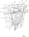
- Fig. 2 shows a perspective interior view of the channel section 8a, which is arranged upstream of the treatment chamber 3 in the direction of flow and in which the additional heating element 23 is located.
- the additional heating element 23 comprises a block 23b with an electrically operated resistance heating element. When electrical energy is supplied, this and the surrounding metal block 23b heat up. Cooling fins 23a are attached to the block 23b, preferably along the direction of flow of the process air PL in this channel section 8a.
- the supply line 21 ends inside the channel section 8a with a nozzle 21a or an open line end.
- the distribution element 24 is attached between the line end and the upper side of the heating element 23. It comprises a base body 30, which is designed as a flat block and is attached in an inclined position.
- a channel-like channel system is incorporated into the block 30 on the side facing the end of the line, which comprises a point inlet 31, from this two outward-facing channels 32 and from these a further branching into further channels 33.
- the further channels 33 end at the edge 34 of the block 30, so that the water flowing in the channels 32, 33 drips off the block 30 due to gravity or flows downwards onto the heating element 23.
- the inclined position of the block 30 means that the water hitting the point inlet 31 can flow downwards through the channels 32, 33 due to gravity and can flow out at the open ends 34 of the branches 33.
- the block 30 is mounted at an angle of 20° to 60° to the horizontal, preferably 30° to 45° in the channel section 8a, also referred to as the supply air channel.
- the distribution element 24 or the block 30 is provided with holding means 35 for fastening on or to the heating element 23.
- the block 30 can consist of a plastic or metal and preferably has a thickness with a value in the range of 2 mm 10 mm, preferably 4 mm.
- the channels 31, 32, 33 can be milled on the top and preferably have a width in the range of 1 mm to 10 mm, preferably 2 mm to 4 mm, and a depth in the range of 0.5 mm to 5 mm, preferably 1 mm to 2 mm.
- the base of the channels 31, 32, 33 can be curved in profile.
- All direction and position information refers to the normal operating position of the treatment device 1.
Landscapes
- Engineering & Computer Science (AREA)
- Textile Engineering (AREA)
- Detail Structures Of Washing Machines And Dryers (AREA)
Description
- Die Erfindung betrifft ein Wäschebehandlungsgerät.
- Wäsche ist zum Teil nicht optisch schmutzig aber mit Geruchs- und Schadstoffen belastet. In der Regel wird die Wäsche daher nach gewisser Zeit oder Beanspruchung gewaschen und anschließend im Trockner oder auf der Leine getrocknet. Das Waschen und anschließende Trocknen erfordert viel Zeit, Energie und händische Tätigkeiten seitens des Benutzers.
- Die
EP 2 415 926 A2 offenbart einen Wäschetrockner mit einem Dampferzeuger zur Wäschebehandlung. Als Dampferzeuger dient das Heizelement zum Erhitzen der Prozessluft, wobei eine Rohrleitung vom Wassertank bis nah zum Heizelement geführt ist, um auf einen Teilbereich Wasser zuzuführen. Die Verteilung des Wassers erfolgt dadurch, dass die Rohrleitung Zickzack-artig über dem besagten Teilbereich des Heizelements geführt ist. - Das Dokument
US 212/131 811 A1 offenbart einen Waschtrockner mit einer Wärmepumpenvorrichtung zum Konditionieren der Prozessluft. In einem horizontal verlaufenden Kanalabschnitt, der sich oberhalb der Trommel befindet, ist ein zusätzliches Heizelement angebracht, zu dem Wasser aufgesprüht wird. - Das Dokument
US 2017/175 320 A1 offenbart einen Trommeltrockner mit einer Wärmepumpenvorrichtung zum Konditionieren der Prozessluft. Im Prozessluftkanal ist dem Wärmetauscher nachgeschaltet ein zusätzliches Heizelement angeordnet, um die Prozessluft; die den Wärmetauscher der Wärmepumpe verlässt, zusätzlich zu erhitzen. - Das Dokument
EP 3 865 620 A1 offenbart auch einen solchen Trommeltrockner mit einer Wärmepumpenvorrichtung und einem zusätzlichen Heizelement zum Konditionieren der Prozessluft. - Der hier vorgestellte Ansatz stellt sich die Aufgabe, ein verbessertes Wäschebehandlungsgerät mit einem Dampferzeuger zum zu schaffen.
- Erfindungsgemäß wird unter anderem diese Aufgabe durch ein Wäschebehandlungsgerät mit den Merkmalen des Anspruchs 1 gelöst. Vorteilhafte Ausgestaltungen und Weiterbildungen der Erfindung ergeben sich aus den abhängigen Ansprüchen.
- Durch den hier vorgestellten Ansatz wird auf einfache Art und Weise eine Möglichkeit geschaffen, die zu behandelnde Wäsche gezielt nachzubehandeln, beispielsweise zu glätten und/oder Geruchsstoffe schonend aus dem Behandlungsgut zu entfernen und abzutransportieren und/oder Duftstoffe zuzuführen.
- Das Wäschebehandlungsgerät weist dabei einen Dampferzeuger mit
- einem Wassertank zur Aufnahme bzw. Bevorratung von Wasser;
- einer Zuführleitung zum Leiten des Wassers aus dem Wassertank in den Kanalabschnitt, in dem das Heizelement angeordnet ist;
- einem Dosierelement welches der Zuführleitung vorgeschaltet ist zum Duschlassen des Wassers oder zum Sperren des Wasserflusses durch die Leitung;
- einem Verteilelement zum Verteilen des aus der Zuführleitung austretenden Wassers auf. Damit wird das ohnehin vorhandene Zusatzheizelement, das zum schnellen Aufheizen der Prozessluft verwendet wird, zusätzlich zur Erzeugung von Dampf verwendet. Dazu wird das Heizelement aktiviert, wodurch es sich erhitzt, wobei Wasser aus der Zuführleitung auf das Heizelement geführt wird. Hierbei wird das ragt das Ende der Zuführleitung nicht direkt zum Heizelement, da zwischen Leitungsende und Heizelement ein Verteilelement angeordnet ist, um den Wasserstrahl auf die stirnseitige Oberfläche des Heizelements zu verteilen. Der Dampf wird also im Kanal vor dem Eintritt in die Behandlungskammer erzeugt und gelangt mit der strömenden Prozessluft in die Behandlungskammer. In der Behandlungskammer entfaltet der Dampf in den dort herumwirbelnden Wäschestücken seine Wirkung, beispielsweise glättend, geruchsentfernend und/oder reinigend und/oder desinfizierend. Mit der Auffächerung des auf das Heizelement gerichteten Wasserstrahls wird eine gleichmäßige Verteilung erreicht und dadurch zuverlässig ein vollständiges Verdampfen des zugeführten Wassers sichergestellt. Insgesamt wird eine gute Qualität des Dampfes erreicht, wobei die Bildung von Wassertropfen in der Prozessluft vermieden wird.
- Das Heizelement ist bevorzugt als flaches Bauteil, bevorzugt mit Kühlrippen, ausgebildet und senkrecht, also längs zur Strömungsrichtung des Prozessluftstromes, im rückseitigen Luftkanal angebracht. Die Zuführleitung ragt in den Luftkanalabschnitt, in dem sich das Heizelement befindet, hinein, wobei zwischen Leitungsende und Zusatzheizung ein Verteilelement angeordnet ist, um das aus dem Leitungsende strömende Wasser zu verteilen bzw. den Wasserstrom aufzufächern. Dadurch wird der austretende Wasserstrahl in mehrere Strahlen aufgefächert, um einen größeren Bereich der stirnseitigen Oberfläche der Zusatzheizung mit Wasser zu beaufschlagen.
- Das Wäschebehandlungsgerät kann beispielsweise als Trockner oder Waschtrockner oder Trockenschrank ausgebildet sein. Im Folgenden wird die Behandlungskammer auch als Trommel bezeichnet, wobei die Trommel zum Einsatz kommt, wenn diese während der Behandlung des Reinigungsgutes gedreht wird zum Durchmischen Reinigungsgutes. In einem Trockenschrank ist die Behandlungskammer der Behandlungsraum, in den das Reinigungsgut ausgehängt werden, wobei hierbei der Behandlungsraum nicht bewegt wird während des Behandlungsprozesses. Unter dem Reinigungsgut können beispielsweise Textilien verstanden werden. Der Reinigungsprozess kann beispielsweise ein Reinigungsprogramm abbilden, das ein Nutzer des Reinigungsgeräts wählen und entsprechend einstellen kann. Der Reinigungsprozess kann unter Verwendung von Einrichtungen des Wäschebehandlungsgerät automatisch durchgeführt werden. Die Trommel kann als drehbarer Aufnahmebehälter ausgeformt sein. Das zusätzliche Heizelement kann eine unabhängig von der Wärmepumpe aktivierbare elektrische Heizeinrichtung sein, die beispielsweise zumindest einen Heizwiderstand umfasst. Die Zuführeinrichtung kann beispielsweise als ein steuerbares Ventil oder als eine Pumpe ausgeformt sein, sodass die zuzuführende Wassermenge der Zusatzheizung kontrolliert zugeführt werden kann.
- Das Wäschebehandlungsgerät kann beispielsweise als ein Haushaltgerät ausgebildet sein, aber auch entsprechend im Zusammenhang mit einem gewerblichen oder professionellen Gerät. Ferner kann es als Trommeltrockner ausgebildet sein, umfassend ein Gehäuse und eine in dem Gehäuse angeordneten, mittels eines Motors antreibbaren, über eine horizontale oder geneigte Achse drehbar gelagerten Trommel, die die Behandlungskammer bildet.
- Das Heizelement ist im Kanal in einem zumindest überwiegend senkrechten Abschnitt vor dem Lufteinlass der Kammer und das Verteilelement oberhalb des Heizelements angeordnet. Das Leitungsende ist in einem Abstand zur Oberseite des zusätzlichen Heizelements bzw. oberhalb des Verteilelements angeordnet. Dadurch ist das in den Kanal ragende Leitungsstück keiner starken Erwärmung ausgesetzt, wenn die Zusatzheizung eingeschaltet ist.
- In einer weiteren, insgesamt vorteilhaften Ausführung umfasst das Heizelement Heizrippen zur Übertragung der Wärme an die vorbeiströmende Prozessluft. Die Kühlrippen sind bevorzugt ebenfalls senkrecht ausgerichtet. Dadurch wird der Luftstrom nicht oder nur wenig beeinträchtigt.
- In einer insgesamt zweckmäßigen Ausführung ist das Dosierelement eine Pumpe oder Ventil, welches mittels der Steuereinrichtung aktivierbar, um Wasser zum Heizelement zu fördern. Besonders die Ausführung mit Ventil und der Anordnung des Wassertanks oberhalb des Heizelements ist sehr einfach und zuverlässig auszubilden, weil bei geöffnetem Ventil das Wasser aufgrund der Schwerkraft auf das Verteilelement gelangt und dort in mehrere Ströme aufgeteilt wird. Die Ausnutzung der Schwerkraft zur Bereitstellung des Wasserflusses gilt für alle Ausführungen.
- In einer insgesamt zweckmäßigen Ausführung ist das Wäschebehandlungsgerät ein Kondensationstrockner, umfassend einen Sammelbehälter für Kondensat, welches beim Trocknungsvorgang entsteht, wobei der Sammelbehälter den Wassertank bildet und das Kondensat zur Dampferzeugung verwendet werden kann. Hierbei wird das beim Trocknungsvorgang anfallende Kondensat zur Dampferzeugung verwendet, sodass der Benutzer kein oder nur wenig Wasser in den Tank nachfüllen muss.
- In einer vorteilhaften Ausführung der Erfindung umfasst das Verteilelement einen Basiskörper mit einem darin eingebrachten rinnenartigen ersten Kanal, in den die Leitung mündet, wobei von diesem ersten Kanal weitere Kanäle abzweigen, um eine Auffächerung des auf das Heizelement zugeführten Wasserstrahls zu bewirken. Dies ist sehr einfach durch Fräsen herzustellen und die offene Ausführung kann nicht verstopfen. Ferner treten Ablagerungen nur in geringem Umfang auf, weil die Kanäle offen im Luftstrom liegen und durch diesen stets freigeblasen werden.
- In einer bevorzugten Weiterbildung ist der Basiskörper derart ausgebildet, dass von dem ersten Kanal zumindest vier weitere Kanäle abzweigen. Ferner können von den weiteren Kanälen nochmal jeweils mehrere, weitere Kanäle abzweigen. Insgesamt sind die Kanäle so geführt, dass sie sich auf der Oberfläche des Basiskörpers zu zwei gegenüberliegenden Seiten hin erstrecken und den einzelnen eintretenden Wasserstrahl in mehrere, zueinander beabstandete Wasserstrahlen aufteilt.
- In einer insgesamt bevorzugten Ausführung ist der Basiskörper als Platte oder Block, bevorzugt aus einem Metall, wie Aluminium oder einem hitzebeständigen Kunststoff, ausgebildet und, schräggestellt im Zuluftkanal angeordnet ist, wobei die offenen Seiten der Rinnen auf der Oberseite der Platte angeordnet sind.
- In einer insgesamt zweckmäßigen Ausführung ist die Platte oder der Block derart dimensioniert, dass die Platte oder der Block eine Dicke im Bereich von 2 mm bis 10 mm, bevorzugt 3 bis 5 mm, die Rinnen eine Breite im Bereich von 1 mm bis 10 mm, bevorzugt 2 mm bis 4 mm, und eine Tiefe im Bereich von 0,5 mm bis 5 mm, bevorzugt 1 mm bis 2 mm, aufweisen. Damit wird eine sichere Führung des auf die Platte auftreffenden Wasserstrahls in die Verzweigungen bereitgestellt. Ein unkontrolliertes Abfließen des Wasserstrahls in unerwünschte Bereiche wird vermieden.
- In einer insgesamt vorteilhaften Ausführung ist der Basiskörper auf der Oberseite, insbesondere die Rinnen, mit einer hydrophoben Oberfläche versehen. Dadurch ist ein vollständiges Abfließen des Wassers vom Verteilelement sichergestellt.
- In einer weiteren, insgesamt vorteilhaften Ausführung ist der Basiskörper mit den rinnenartigen Kanälen derart dimensioniert, dass er die stirnseitige Fläche des Heizelements zu 30% bis 70%, bevorzugt 40% bis 60%, überdeckt. Ferner ist der Basiskörper bevorzugt in einem Winkel im Bereich von 20° bis 60° zur Horizontalen, bevorzugt 30° bis 45° zur Horizontalen im Zuluftkanal angeordnet.
- Ein Ausführungsbeispiel der Erfindung ist in den Zeichnungen rein schematisch dargestellt und wird nachfolgend näher beschrieben. Es zeigen
- Fig. 1:
- eine schematische Darstellung der Komponenten der Wärmepumpe und
- Fig. 2:
- eine detaillierte, perspektivische Ansicht des Dampferzeugers.
-
Fig. 1 zeigt den erfindungsgemäßen Wärmepumpen-Trockner 1 in einer schematischen Schnittdarstellung. Hier ist zu erkennen, dass die Wärmepumpeneinrichtung 13 einen Kältemittelkreislauf umfasst, bei dem Kältemittel in einem Leitungssystem mit einem Verdampfer 15, einem Kompressor 14 zum Verdichten des Kältemittels, einem Verflüssiger 16 und einer Drossel 15a zirkuliert, wobei der Wärmetauscher den Verdampfer 15 und die Heizung den Verflüssiger 16 der Wärmepumpe 13 enthält. Der Verdampfer 15 und der Verflüssiger 16 sind im Kanal 8 derart angeordnet, dass die feuchte Prozessluft PL aus dem Auslass 7 der Behandlungskammer 3 im Kanal 8 zuerst den Verdampfer 15 durchströmt, damit sie aufgrund der Abkühlung und der daraus folgenden Kondensation entfeuchtet wird. Anschließend durchströmt sie den nachgeschalteten Verflüssiger 16, der als Heizung wirkt und die Prozessluft PL aufheizt, sodass die erwärmte Prozessluft PL durch den Lufteinlass 6 in die Trommel 3 eingelassen und damit der zu behandelnden Textilien zugeführt wird. In der Auffangwanne 18 wird anfallendes Kondensat aufgefangen und mittels der Kondensatpumpe 17 zum Sammelbehälter 4 gepumpt. Der Behälter 4 kann in einer anderen Ausführung auch als Tank für Frischwasser ausgebildet sein, wenn Dampf mit Frischwasser erzeugt werden soll. Zur Dampferzeugung umfasst das Behandlungsgerät 1 einen Dampferzeuger 20, zu dem auch der Tank 4 zugeordnet werden kann. Am Tank bzw. in der Zuführungsleitung 21 ist als Dosierelement 22 ein Ventil angebracht, welches von der Steuereinrichtung 19 geöffnet und geschlossen werden kann, um Wasser durch die Leitung 21 zum Zusatzheizelement 23 strömen zu lassen. Um Dampf zu erzeugen, wird das Zusatzheizelement 23 aktiviert, sodass die Oberfläche heiß ist und das darauf strömende Wasser verdampft. Der Dampf wird also in dem Luftkanalabschnitt 8a vor dem Einlass 6 des Luftkanals 8 erzeugt, der unmittelbar der Behandlungskammer 3 vorgeschaltet ist. Oberhalb des Heizelements 23 ist ein Verteilelement 24 angeordnet, in dem ein Kanalsystem 31, 32, 33 (Fig. 2 ) zur flächigen Aufteilung des punktuell einströmenden Wassers angebracht bzw. eingeformt ist. - Das bodenseitige Funktionsmodul 5 umfasst ferner den Motor 10, der hier das Gebläse 9 und die Trommel 3 antreibt. Das Gebläse 9 ist bevorzugt als Radiallüfter mit gekrümmten Schaufeln ausgebildet, sodass es in einer Vorzugsrichtung einen höheren Volumenstrom verursacht, als in der Gegendrehrichtung. Die als drehbare Trommel 3 ausgebildete Behandlungskammer ist mittels einer horizontalen oder geneigten Drehachse 40 im Gehäuse 2 oder an einem Tragwerk gelagert.
-
Fig. 2 zeigt eine perspektivische Innenansicht des der Behandlungskammer 3 in Strömungsrichtung vorgeschalteten Kanalabschnitt 8a, in dem sich das Zusatzheizelement 23 befindet. Das Zusatzheizelement 23 umfasst einen Block 23b mit einem elektrisch betreibbaren Widerstandsheizelement. Bei Zuführung von elektrischer Energie erhitzt sich dieser und den umgebenden Metallblock 23b. An dem Block 23b sind Kühlrippen 23a angebracht, bevorzugt längs zur Strömungsrichtung der Prozessluft PL in diesem Kanalabschnitt 8a. Oberhalb des Zusatzheizelements 23 endet im Inneren des Kanalabschnitts 8a die Zuführleitung 21 mit einer Düse 21a oder einem offenen Leitungsende. Zwischen Leitungsende und der oberen Seite des Heizelements 23 ist das Verteilelement 24 angebracht. Es umfasst einen Basiskörper 30, der als flacher Block ausgebildet ist und in einer geneigten Lage angebracht ist. In dem Block 30 ist auf der dem Leitungsende zugewandten Seite ein rinnenartiges Kanalsystem eingearbeitet, welches einen punktuellen Einlass 31, von diesem ausgehend zwei nach außen gerichtete Kanäle 32 und von diesen ausgehend eine weitere Verzweigung in weitere Kanäle 33 umfasst. Die weiteren Kanäle 33 enden an der Kante 34 des Blocks 30, sodass das in den Kanälen 32, 33 fließende Wasser vom Block 30 aufgrund der Schwerkraft abtropft bzw. nach unten auf das Heizelement 23 fließt. Die Schrägstellung des Blocks 30 bewirkt, dass das auf den punktuellen Einlass 31 auftreffende Wasser aufgrund der Schwerkraft durch die Rinnen 32, 33 nach unten strömen kann und an den offenen Enden 34 der Verzweigungen 33 abfließen kann. Der Block 30 ist dabei in einem Winkel von 20° bis 60° zur Horizontalen, bevorzugt 30° bis 45° in dem Kanalabschnitt 8a, auch als Zuluftkanal bezeichnet, angebracht. Das Verteilelement 24 bzw. der Block 30 ist mit Haltemitteln 35 versehen zur Befestigung auf oder an dem Heizelement 23. Der Block 30 kann aus einem Kunstsoff oder Metall bestehen und weist bevorzugt eine Dicke mit einem Wert im Bereich von 2 mm 10 mm, bevorzugt 4 mm, auf. Auf der Oberseite können die Kanäle 31, 32, 33 eingefräst sein und weisen bevorzugt eine Breite im Bereich von 1 mm bis 10 mm, bevorzugt 2 mm bis 4 mm, und eine Tiefe im Bereich von 0,5 mm bis 5 mm, bevorzugt 1 mm bis 2 mm, auf. Der Grund der Rinnen 31, 32, 33 kann im Profil gewölbt sein. - Alle Richtungs- und Positionsangaben beziehen sich auf die betriebsgemäße Aufstellposition des Behandlungsgerätes 1.
Claims (14)
- Wäschebehandlungsgerät (1) mit folgenden Merkmalen:einer Behandlungskammer, bevorzugt eine Trommel (3) zum Aufnehmen von Wäsche, die einen Lufteinlass (6) und einen Luftauslass (7) aufweist;ein Aggregat mit- einer Wärmepumpe (13) mit einem Kompressor (14) Verflüssiger (16) als Heizeinrichtung und einem Verdampfer (15) als Kondensationseinrichtung;- einem Lüfter (9, 10) zum Fördern von Prozessluft (PL) durch einen durch die Behandlungskammer (3) und die Heizeinrichtung (16) führenden Kreislauf;- einen Prozessluftkanal (8) zur Verbindung des Aggregats (13) mit dem Lufteinlass (6) und dem Luftauslass (7) der Behandlungskammer (3);- ein in dem Prozessluftkanal (8, 8a) befindlichen zusätzlichen Heizelement (23);- einer Steuereinrichtung (19) zum Aktivieren und Deaktivieren des Lüfters (10, 9), des Kompressors (14) und des zusätzlichen Heizelements (23) zur Durchführung eines automatischen Behandlungsablaufs,ferner umfassend- einen Dampferzeuger (20) mit- einem Wassertank (4) zur Aufnahme bzw. Bevorratung von Wasser;- einer Zuführleitung (21) zum Leiten des Wassers aus dem Wassertank (4) in den Kanalabschnitt (8a), in dem das zusätzliche Heizelement (23) angeordnet ist;- einem Dosierelement (22) welches der Zuführleitung (21) vorgeschaltet ist zum Duschlassen des Wassers oder zum Sperren des Wasserflusses durch die Leitung (21);- einem Verteilelement (24) zum Verteilen des aus der Zuführleitung (21) austretenden Wassers,dadurch gekennzeichnet,dass das zusätzliche Heizelement (23) im Kanal (8a) in einem zumindest überwiegend senkrechten Abschnitt vor dem Lufteinlass (6) der Kammer (3) angeordnet ist, wobei die Zuführleitung in den Luftkanalabschnitt hineinragt, in dem sich das zusätzliche Heizelement (23) befindet, wobei zwischen Leitungsende und dem zusätzlichen Heizelement (23) das Verteilelement (24) oberhalb des zusätzlichen Heizelements (23) angeordnet ist, um das aus dem Leitungsende strömende Wasser zu verteilen bzw. den Wasserstrom aufzufächern, damit es am aktivierten zusätzlichen Heizelement (23) verdampfen kann.
- Wäschebehandlungsgerät nach Anspruch 1, welches als Trommeltrockner ausgebildet ist, umfassend ein Gehäuse (2) und eine in dem Gehäuse (2) angeordneten, mittels eines Motors (10) antreibbaren, über eine horizontale oder geneigte Achse (5) drehbar gelagerten Trommel (3), die die Behandlungskammer bildet.
- Wäschebehandlungsgerät nach einem der Ansprüche 1 bis 2, wobei das zusätzliche Heizelement (23) Kühlrippen (23a) zur Übertragung der Wärme an die vorbeiströmende Prozessluft (PL) umfasst.
- Wäschebehandlungsgerät nach einem der Ansprüche 1 bis 3,
wobei das Dosierelement (22) eine Pumpe oder Ventil ist, welches mittels der Steuereinrichtung (19) aktivierbar ist, um Wasser zum zusätzlichen Heizelement (23) zu fördern. - Wäschebehandlungsgerät nach einem der Ansprüche 1 bis 4,
ferner umfassend einen Sammelbehälter (4) für Kondensat, welches beim Trocknungsvorgang entsteht, wobei der Sammelbehälter (4) den Wassertank bildet und das Kondensat zur Dampferzeugung dient. - Wäschebehandlungsgerät nach einem der Ansprüche 1 bis 5,
wobei das Verteilelement (24) einen Basiskörper (30) mit einem darin eingebrachten rinnenartigen ersten Kanal (32) umfasst, in den die Leitung (21) mündet. - Wäschebehandlungsgerät nach Anspruch 6,
wobei von diesem ersten Kanal (32) weitere Kanäle (33) abzweigen, um eine Auffächerung des auf das zusätzliche Heizelement (23) zugeführten Wasserstrahls zu bewirken. - Wäschebehandlungsgerät nach Anspruch 6 oder 7,
wobei von dem ersten Kanal (32) zumindest zwei weitere Kanäle (33) abzweigen. - Wäschebehandlungsgerät nach Anspruch 7 oder 8,
wobei von den weiteren Kanälen (33) nochmal jeweils mehrere, weitere Kanäle abzweigen. - Wäschebehandlungsgerät nach einem der Ansprüche 6 bis 9,
wobei der Basiskörper als Platte oder Block (30) ausgebildet und, schräggestellt im Zuluftkanal (8a) angeordnet ist, wobei die offenen Seiten der rinnenartigen Kanäle (31, 32, 33) auf der Oberseite der Platte oder Blocks (30) angeordnet sind. - Wäschebehandlungsgerät nach einem der Ansprüche 6 bis 10,
wobei die Platte oder Block (30) eine Dicke im Bereich von 2 mm bis 10 mm, bevorzugt 3 bis 5 mm, die rinnenartigen Kanäle (31, 32, 33) eine Breite im Bereich von 1 mm bis 10 mm, bevorzugt 2 mm bis 4 mm, und eine Tiefe im Bereich von 0,5 mm bis 5 mm, bevorzugt 1 mm bis 2 mm, aufweisen. - Wäschebehandlungsgerät nach einem der Ansprüche 6 bis 11,
wobei der Basiskörper (30) auf der Oberseite, insbesondere die rinnenartigen Kanäle (31, 32, 33), mit einer hydrophoben Oberfläche versehen ist / sind. - Wäschebehandlungsgerät nach einem der Ansprüche 6 bis 12,
wobei der Basiskörper (30) mit den rinnenartigen Kanälen derart dimensioniert ist, dass er die stirnseitige Fläche des zusätzliche Heizelements (23) zu 30% bis 70%, bevorzugt 40% bis 60%, überdeckt. - Wäschebehandlungsgerät nach einem der Ansprüche 6 bis 13,
wobei der Basiskörper (30) in einem Winkel im Bereich von 20° bis 60° zur Horizontalen, bevorzugt 30° bis 45° zur Horizontalen im Zuluftkanal (8a) angeordnet ist.
Applications Claiming Priority (1)
| Application Number | Priority Date | Filing Date | Title |
|---|---|---|---|
| BE20215697A BE1029736B1 (de) | 2021-09-08 | 2021-09-08 | Wärmepumpentrockner mit Dampferzeuger |
Publications (3)
| Publication Number | Publication Date |
|---|---|
| EP4148179A1 EP4148179A1 (de) | 2023-03-15 |
| EP4148179B1 true EP4148179B1 (de) | 2024-11-20 |
| EP4148179C0 EP4148179C0 (de) | 2024-11-20 |
Family
ID=79425375
Family Applications (1)
| Application Number | Title | Priority Date | Filing Date |
|---|---|---|---|
| EP22192098.6A Active EP4148179B1 (de) | 2021-09-08 | 2022-08-25 | Wärmepumpentrockner mit dampferzeuger |
Country Status (2)
| Country | Link |
|---|---|
| EP (1) | EP4148179B1 (de) |
| BE (1) | BE1029736B1 (de) |
Family Cites Families (4)
| Publication number | Priority date | Publication date | Assignee | Title |
|---|---|---|---|---|
| WO2010114332A2 (ko) | 2009-04-02 | 2010-10-07 | (주)엘지전자 | 열풍히터를 이용한 스팀발생기를 구비한 의류건조기 |
| EP3425108B1 (de) * | 2009-06-29 | 2020-12-16 | Electrolux Home Products Corporation N.V. | Vorrichtung zum wäschetrocknen |
| US10648125B2 (en) * | 2015-12-18 | 2020-05-12 | Whirlpool Corporation | Laundry treating appliance and method of operation |
| DE102020103796A1 (de) * | 2020-02-13 | 2021-08-19 | Miele & Cie. Kg | Trockner |
-
2021
- 2021-09-08 BE BE20215697A patent/BE1029736B1/de not_active IP Right Cessation
-
2022
- 2022-08-25 EP EP22192098.6A patent/EP4148179B1/de active Active
Also Published As
| Publication number | Publication date |
|---|---|
| BE1029736A1 (de) | 2023-03-30 |
| BE1029736B1 (de) | 2023-04-03 |
| EP4148179A1 (de) | 2023-03-15 |
| EP4148179C0 (de) | 2024-11-20 |
Similar Documents
| Publication | Publication Date | Title |
|---|---|---|
| EP2196577B1 (de) | Trockner mit umluftanteil sowie verfahren zu seinem betrieb | |
| DE3842997C2 (de) | Geschirrspülmaschine | |
| EP3041984B1 (de) | Verteilen einer flüssigkeit in einem haushaltsgerät | |
| DE4235560A1 (de) | Verfahren zum Entgiften, Lüften, Trocknen und Sterilisieren von Geweben und dergleichen sowie Gerät zur Durchführung des Verfahrens | |
| EP1284627A2 (de) | Vorrichtung zum trocknen von geschirr in einer geschirrspülmaschine | |
| DE112013003451T5 (de) | Wäschetrocknungsmaschine und Wasch- und Trocknungsmaschine | |
| EP0082443B1 (de) | Reinigungsanlage zum chemischen Reinigen von Gegenständen aus Stoff | |
| EP2516720A1 (de) | Filtervorrichtung, hausgerät und verfahren zum filtern | |
| DE3901170A1 (de) | Geschirrspuelmaschine mit entlueftungsoeffnung | |
| DE102014010498B4 (de) | Verfahren zum Trocknen von Wäsche und Trockner | |
| BE1029736B1 (de) | Wärmepumpentrockner mit Dampferzeuger | |
| DE3148573A1 (de) | Waeschetrockner der trommelbauart | |
| EP1321082A2 (de) | Vorrichtung zur Wärmebehandlung von Substanzen, insbesondere Nahrungsmitteln | |
| BE1030320B1 (de) | Wärmepumpentrockner mit Dampferzeuger | |
| DE3123886C2 (de) | "Verfahren und Vorrichtung zur Führung der Luft an einer Mangel" | |
| BE1031943B1 (de) | Wäschebehandlungsschrank mit Dampferzeuger | |
| EP4137031B1 (de) | Gewerbliche geschirrspülmaschine und verfahren zum betreiben einer solchen | |
| DE3034168A1 (de) | Apparat zum trocknen von waesche in einem gebaeuderaum | |
| DE102021212638A1 (de) | Einspülsystem, wasserführendes Haushaltsgerät und Verfahren zum Leiten von Fluid | |
| EP3786343A1 (de) | Wäschebehandlungsgerät | |
| BE1031551B1 (de) | Wäschebehandlungsschrank mit einer Vorrichtung zur Konditionierung der Innenraumluft | |
| DE102024102208A1 (de) | Wäschebehandlungsschrank mit Sprühvorrichtung | |
| DE102023121684A1 (de) | Wäschebehandlungsschrank mit Dampferzeuger | |
| DE102021103231B4 (de) | Gewerbliche Geschirrspülmaschine und Verfahren zum Betreiben einer solchen | |
| DE69907076T2 (de) | Waschtrockner |
Legal Events
| Date | Code | Title | Description |
|---|---|---|---|
| PUAI | Public reference made under article 153(3) epc to a published international application that has entered the european phase |
Free format text: ORIGINAL CODE: 0009012 |
|
| STAA | Information on the status of an ep patent application or granted ep patent |
Free format text: STATUS: THE APPLICATION HAS BEEN PUBLISHED |
|
| AK | Designated contracting states |
Kind code of ref document: A1 Designated state(s): AL AT BE BG CH CY CZ DE DK EE ES FI FR GB GR HR HU IE IS IT LI LT LU LV MC MK MT NL NO PL PT RO RS SE SI SK SM TR |
|
| STAA | Information on the status of an ep patent application or granted ep patent |
Free format text: STATUS: REQUEST FOR EXAMINATION WAS MADE |
|
| 17P | Request for examination filed |
Effective date: 20230915 |
|
| RBV | Designated contracting states (corrected) |
Designated state(s): AL AT BE BG CH CY CZ DE DK EE ES FI FR GB GR HR HU IE IS IT LI LT LU LV MC MK MT NL NO PL PT RO RS SE SI SK SM TR |
|
| GRAP | Despatch of communication of intention to grant a patent |
Free format text: ORIGINAL CODE: EPIDOSNIGR1 |
|
| STAA | Information on the status of an ep patent application or granted ep patent |
Free format text: STATUS: GRANT OF PATENT IS INTENDED |
|
| RIC1 | Information provided on ipc code assigned before grant |
Ipc: D06F 25/00 20060101ALN20240626BHEP Ipc: D06F 58/02 20060101ALN20240626BHEP Ipc: D06F 58/20 20060101AFI20240626BHEP |
|
| INTG | Intention to grant announced |
Effective date: 20240712 |
|
| GRAS | Grant fee paid |
Free format text: ORIGINAL CODE: EPIDOSNIGR3 |
|
| GRAA | (expected) grant |
Free format text: ORIGINAL CODE: 0009210 |
|
| STAA | Information on the status of an ep patent application or granted ep patent |
Free format text: STATUS: THE PATENT HAS BEEN GRANTED |
|
| AK | Designated contracting states |
Kind code of ref document: B1 Designated state(s): AL AT BE BG CH CY CZ DE DK EE ES FI FR GB GR HR HU IE IS IT LI LT LU LV MC MK MT NL NO PL PT RO RS SE SI SK SM TR |
|
| REG | Reference to a national code |
Ref country code: GB Ref legal event code: FG4D Free format text: NOT ENGLISH |
|
| REG | Reference to a national code |
Ref country code: CH Ref legal event code: EP |
|
| REG | Reference to a national code |
Ref country code: DE Ref legal event code: R096 Ref document number: 502022002165 Country of ref document: DE |
|
| REG | Reference to a national code |
Ref country code: IE Ref legal event code: FG4D Free format text: LANGUAGE OF EP DOCUMENT: GERMAN |
|
| U01 | Request for unitary effect filed |
Effective date: 20241120 |
|
| U07 | Unitary effect registered |
Designated state(s): AT BE BG DE DK EE FI FR IT LT LU LV MT NL PT RO SE SI Effective date: 20241126 |
|
| PG25 | Lapsed in a contracting state [announced via postgrant information from national office to epo] |
Ref country code: HR Free format text: LAPSE BECAUSE OF FAILURE TO SUBMIT A TRANSLATION OF THE DESCRIPTION OR TO PAY THE FEE WITHIN THE PRESCRIBED TIME-LIMIT Effective date: 20241120 Ref country code: IS Free format text: LAPSE BECAUSE OF FAILURE TO SUBMIT A TRANSLATION OF THE DESCRIPTION OR TO PAY THE FEE WITHIN THE PRESCRIBED TIME-LIMIT Effective date: 20250320 |
|
| PG25 | Lapsed in a contracting state [announced via postgrant information from national office to epo] |
Ref country code: ES Free format text: LAPSE BECAUSE OF FAILURE TO SUBMIT A TRANSLATION OF THE DESCRIPTION OR TO PAY THE FEE WITHIN THE PRESCRIBED TIME-LIMIT Effective date: 20241120 |
|
| PG25 | Lapsed in a contracting state [announced via postgrant information from national office to epo] |
Ref country code: NO Free format text: LAPSE BECAUSE OF FAILURE TO SUBMIT A TRANSLATION OF THE DESCRIPTION OR TO PAY THE FEE WITHIN THE PRESCRIBED TIME-LIMIT Effective date: 20250220 |
|
| PG25 | Lapsed in a contracting state [announced via postgrant information from national office to epo] |
Ref country code: GR Free format text: LAPSE BECAUSE OF FAILURE TO SUBMIT A TRANSLATION OF THE DESCRIPTION OR TO PAY THE FEE WITHIN THE PRESCRIBED TIME-LIMIT Effective date: 20250221 |
|
| PG25 | Lapsed in a contracting state [announced via postgrant information from national office to epo] |
Ref country code: PL Free format text: LAPSE BECAUSE OF FAILURE TO SUBMIT A TRANSLATION OF THE DESCRIPTION OR TO PAY THE FEE WITHIN THE PRESCRIBED TIME-LIMIT Effective date: 20241120 |
|
| PG25 | Lapsed in a contracting state [announced via postgrant information from national office to epo] |
Ref country code: RS Free format text: LAPSE BECAUSE OF FAILURE TO SUBMIT A TRANSLATION OF THE DESCRIPTION OR TO PAY THE FEE WITHIN THE PRESCRIBED TIME-LIMIT Effective date: 20250220 |
|
| PG25 | Lapsed in a contracting state [announced via postgrant information from national office to epo] |
Ref country code: SM Free format text: LAPSE BECAUSE OF FAILURE TO SUBMIT A TRANSLATION OF THE DESCRIPTION OR TO PAY THE FEE WITHIN THE PRESCRIBED TIME-LIMIT Effective date: 20241120 |
|
| PG25 | Lapsed in a contracting state [announced via postgrant information from national office to epo] |
Ref country code: SK Free format text: LAPSE BECAUSE OF FAILURE TO SUBMIT A TRANSLATION OF THE DESCRIPTION OR TO PAY THE FEE WITHIN THE PRESCRIBED TIME-LIMIT Effective date: 20241120 |
|
| PG25 | Lapsed in a contracting state [announced via postgrant information from national office to epo] |
Ref country code: CZ Free format text: LAPSE BECAUSE OF FAILURE TO SUBMIT A TRANSLATION OF THE DESCRIPTION OR TO PAY THE FEE WITHIN THE PRESCRIBED TIME-LIMIT Effective date: 20241120 |
|
| PLBE | No opposition filed within time limit |
Free format text: ORIGINAL CODE: 0009261 |
|
| STAA | Information on the status of an ep patent application or granted ep patent |
Free format text: STATUS: NO OPPOSITION FILED WITHIN TIME LIMIT |
|
| U20 | Renewal fee for the european patent with unitary effect paid |
Year of fee payment: 4 Effective date: 20250901 |
|
| PGFP | Annual fee paid to national office [announced via postgrant information from national office to epo] |
Ref country code: TR Payment date: 20250811 Year of fee payment: 4 |
|
| 26N | No opposition filed |
Effective date: 20250821 |
|
| REG | Reference to a national code |
Ref country code: CH Ref legal event code: H13 Free format text: ST27 STATUS EVENT CODE: U-0-0-H10-H13 (AS PROVIDED BY THE NATIONAL OFFICE) Effective date: 20260324 |
|
| PG25 | Lapsed in a contracting state [announced via postgrant information from national office to epo] |
Ref country code: MC Free format text: LAPSE BECAUSE OF FAILURE TO SUBMIT A TRANSLATION OF THE DESCRIPTION OR TO PAY THE FEE WITHIN THE PRESCRIBED TIME-LIMIT Effective date: 20241120 |
|
| PG25 | Lapsed in a contracting state [announced via postgrant information from national office to epo] |
Ref country code: CH Free format text: LAPSE BECAUSE OF NON-PAYMENT OF DUE FEES Effective date: 20250831 |