EP4147860A1 - Vibration welding device and vibration welding method - Google Patents
Vibration welding device and vibration welding method Download PDFInfo
- Publication number
- EP4147860A1 EP4147860A1 EP21195906.9A EP21195906A EP4147860A1 EP 4147860 A1 EP4147860 A1 EP 4147860A1 EP 21195906 A EP21195906 A EP 21195906A EP 4147860 A1 EP4147860 A1 EP 4147860A1
- Authority
- EP
- European Patent Office
- Prior art keywords
- clamping
- vibration welding
- component
- axis
- stack
- Prior art date
- Legal status (The legal status is an assumption and is not a legal conclusion. Google has not performed a legal analysis and makes no representation as to the accuracy of the status listed.)
- Pending
Links
Images


Classifications
-
- B—PERFORMING OPERATIONS; TRANSPORTING
- B29—WORKING OF PLASTICS; WORKING OF SUBSTANCES IN A PLASTIC STATE IN GENERAL
- B29C—SHAPING OR JOINING OF PLASTICS; SHAPING OF MATERIAL IN A PLASTIC STATE, NOT OTHERWISE PROVIDED FOR; AFTER-TREATMENT OF THE SHAPED PRODUCTS, e.g. REPAIRING
- B29C65/00—Joining or sealing of preformed parts, e.g. welding of plastics materials; Apparatus therefor
- B29C65/02—Joining or sealing of preformed parts, e.g. welding of plastics materials; Apparatus therefor by heating, with or without pressure
- B29C65/06—Joining or sealing of preformed parts, e.g. welding of plastics materials; Apparatus therefor by heating, with or without pressure using friction, e.g. spin welding
-
- B—PERFORMING OPERATIONS; TRANSPORTING
- B29—WORKING OF PLASTICS; WORKING OF SUBSTANCES IN A PLASTIC STATE IN GENERAL
- B29C—SHAPING OR JOINING OF PLASTICS; SHAPING OF MATERIAL IN A PLASTIC STATE, NOT OTHERWISE PROVIDED FOR; AFTER-TREATMENT OF THE SHAPED PRODUCTS, e.g. REPAIRING
- B29C66/00—General aspects of processes or apparatus for joining preformed parts
- B29C66/80—General aspects of machine operations or constructions and parts thereof
- B29C66/83—General aspects of machine operations or constructions and parts thereof characterised by the movement of the joining or pressing tools
- B29C66/832—Reciprocating joining or pressing tools
- B29C66/8322—Joining or pressing tools reciprocating along one axis
-
- B—PERFORMING OPERATIONS; TRANSPORTING
- B29—WORKING OF PLASTICS; WORKING OF SUBSTANCES IN A PLASTIC STATE IN GENERAL
- B29C—SHAPING OR JOINING OF PLASTICS; SHAPING OF MATERIAL IN A PLASTIC STATE, NOT OTHERWISE PROVIDED FOR; AFTER-TREATMENT OF THE SHAPED PRODUCTS, e.g. REPAIRING
- B29C65/00—Joining or sealing of preformed parts, e.g. welding of plastics materials; Apparatus therefor
- B29C65/02—Joining or sealing of preformed parts, e.g. welding of plastics materials; Apparatus therefor by heating, with or without pressure
-
- B—PERFORMING OPERATIONS; TRANSPORTING
- B29—WORKING OF PLASTICS; WORKING OF SUBSTANCES IN A PLASTIC STATE IN GENERAL
- B29C—SHAPING OR JOINING OF PLASTICS; SHAPING OF MATERIAL IN A PLASTIC STATE, NOT OTHERWISE PROVIDED FOR; AFTER-TREATMENT OF THE SHAPED PRODUCTS, e.g. REPAIRING
- B29C65/00—Joining or sealing of preformed parts, e.g. welding of plastics materials; Apparatus therefor
- B29C65/02—Joining or sealing of preformed parts, e.g. welding of plastics materials; Apparatus therefor by heating, with or without pressure
- B29C65/06—Joining or sealing of preformed parts, e.g. welding of plastics materials; Apparatus therefor by heating, with or without pressure using friction, e.g. spin welding
- B29C65/0609—Joining or sealing of preformed parts, e.g. welding of plastics materials; Apparatus therefor by heating, with or without pressure using friction, e.g. spin welding characterised by the movement of the parts to be joined
- B29C65/0618—Linear
-
- B—PERFORMING OPERATIONS; TRANSPORTING
- B29—WORKING OF PLASTICS; WORKING OF SUBSTANCES IN A PLASTIC STATE IN GENERAL
- B29C—SHAPING OR JOINING OF PLASTICS; SHAPING OF MATERIAL IN A PLASTIC STATE, NOT OTHERWISE PROVIDED FOR; AFTER-TREATMENT OF THE SHAPED PRODUCTS, e.g. REPAIRING
- B29C65/00—Joining or sealing of preformed parts, e.g. welding of plastics materials; Apparatus therefor
- B29C65/02—Joining or sealing of preformed parts, e.g. welding of plastics materials; Apparatus therefor by heating, with or without pressure
- B29C65/14—Joining or sealing of preformed parts, e.g. welding of plastics materials; Apparatus therefor by heating, with or without pressure using wave energy, i.e. electromagnetic radiation, or particle radiation
- B29C65/1403—Joining or sealing of preformed parts, e.g. welding of plastics materials; Apparatus therefor by heating, with or without pressure using wave energy, i.e. electromagnetic radiation, or particle radiation characterised by the type of electromagnetic or particle radiation
- B29C65/1412—Infrared [IR] radiation
-
- B—PERFORMING OPERATIONS; TRANSPORTING
- B29—WORKING OF PLASTICS; WORKING OF SUBSTANCES IN A PLASTIC STATE IN GENERAL
- B29C—SHAPING OR JOINING OF PLASTICS; SHAPING OF MATERIAL IN A PLASTIC STATE, NOT OTHERWISE PROVIDED FOR; AFTER-TREATMENT OF THE SHAPED PRODUCTS, e.g. REPAIRING
- B29C65/00—Joining or sealing of preformed parts, e.g. welding of plastics materials; Apparatus therefor
- B29C65/72—Joining or sealing of preformed parts, e.g. welding of plastics materials; Apparatus therefor by combined operations or combined techniques, e.g. welding and stitching
-
- B—PERFORMING OPERATIONS; TRANSPORTING
- B29—WORKING OF PLASTICS; WORKING OF SUBSTANCES IN A PLASTIC STATE IN GENERAL
- B29C—SHAPING OR JOINING OF PLASTICS; SHAPING OF MATERIAL IN A PLASTIC STATE, NOT OTHERWISE PROVIDED FOR; AFTER-TREATMENT OF THE SHAPED PRODUCTS, e.g. REPAIRING
- B29C65/00—Joining or sealing of preformed parts, e.g. welding of plastics materials; Apparatus therefor
- B29C65/78—Means for handling the parts to be joined, e.g. for making containers or hollow articles, e.g. means for handling sheets, plates, web-like materials, tubular articles, hollow articles or elements to be joined therewith; Means for discharging the joined articles from the joining apparatus
- B29C65/7841—Holding or clamping means for handling purposes
-
- B—PERFORMING OPERATIONS; TRANSPORTING
- B29—WORKING OF PLASTICS; WORKING OF SUBSTANCES IN A PLASTIC STATE IN GENERAL
- B29C—SHAPING OR JOINING OF PLASTICS; SHAPING OF MATERIAL IN A PLASTIC STATE, NOT OTHERWISE PROVIDED FOR; AFTER-TREATMENT OF THE SHAPED PRODUCTS, e.g. REPAIRING
- B29C66/00—General aspects of processes or apparatus for joining preformed parts
- B29C66/01—General aspects dealing with the joint area or with the area to be joined
- B29C66/02—Preparation of the material, in the area to be joined, prior to joining or welding
- B29C66/024—Thermal pre-treatments
- B29C66/0242—Heating, or preheating, e.g. drying
-
- B—PERFORMING OPERATIONS; TRANSPORTING
- B29—WORKING OF PLASTICS; WORKING OF SUBSTANCES IN A PLASTIC STATE IN GENERAL
- B29C—SHAPING OR JOINING OF PLASTICS; SHAPING OF MATERIAL IN A PLASTIC STATE, NOT OTHERWISE PROVIDED FOR; AFTER-TREATMENT OF THE SHAPED PRODUCTS, e.g. REPAIRING
- B29C66/00—General aspects of processes or apparatus for joining preformed parts
- B29C66/01—General aspects dealing with the joint area or with the area to be joined
- B29C66/05—Particular design of joint configurations
- B29C66/10—Particular design of joint configurations particular design of the joint cross-sections
- B29C66/11—Joint cross-sections comprising a single joint-segment, i.e. one of the parts to be joined comprising a single joint-segment in the joint cross-section
- B29C66/112—Single lapped joints
- B29C66/1122—Single lap to lap joints, i.e. overlap joints
-
- B—PERFORMING OPERATIONS; TRANSPORTING
- B29—WORKING OF PLASTICS; WORKING OF SUBSTANCES IN A PLASTIC STATE IN GENERAL
- B29C—SHAPING OR JOINING OF PLASTICS; SHAPING OF MATERIAL IN A PLASTIC STATE, NOT OTHERWISE PROVIDED FOR; AFTER-TREATMENT OF THE SHAPED PRODUCTS, e.g. REPAIRING
- B29C66/00—General aspects of processes or apparatus for joining preformed parts
- B29C66/40—General aspects of joining substantially flat articles, e.g. plates, sheets or web-like materials; Making flat seams in tubular or hollow articles; Joining single elements to substantially flat surfaces
- B29C66/41—Joining substantially flat articles ; Making flat seams in tubular or hollow articles
- B29C66/45—Joining of substantially the whole surface of the articles
-
- B—PERFORMING OPERATIONS; TRANSPORTING
- B29—WORKING OF PLASTICS; WORKING OF SUBSTANCES IN A PLASTIC STATE IN GENERAL
- B29C—SHAPING OR JOINING OF PLASTICS; SHAPING OF MATERIAL IN A PLASTIC STATE, NOT OTHERWISE PROVIDED FOR; AFTER-TREATMENT OF THE SHAPED PRODUCTS, e.g. REPAIRING
- B29C66/00—General aspects of processes or apparatus for joining preformed parts
- B29C66/70—General aspects of processes or apparatus for joining preformed parts characterised by the composition, physical properties or the structure of the material of the parts to be joined; Joining with non-plastics material
- B29C66/72—General aspects of processes or apparatus for joining preformed parts characterised by the composition, physical properties or the structure of the material of the parts to be joined; Joining with non-plastics material characterised by the structure of the material of the parts to be joined
- B29C66/723—General aspects of processes or apparatus for joining preformed parts characterised by the composition, physical properties or the structure of the material of the parts to be joined; Joining with non-plastics material characterised by the structure of the material of the parts to be joined being multi-layered
-
- B—PERFORMING OPERATIONS; TRANSPORTING
- B29—WORKING OF PLASTICS; WORKING OF SUBSTANCES IN A PLASTIC STATE IN GENERAL
- B29C—SHAPING OR JOINING OF PLASTICS; SHAPING OF MATERIAL IN A PLASTIC STATE, NOT OTHERWISE PROVIDED FOR; AFTER-TREATMENT OF THE SHAPED PRODUCTS, e.g. REPAIRING
- B29C66/00—General aspects of processes or apparatus for joining preformed parts
- B29C66/70—General aspects of processes or apparatus for joining preformed parts characterised by the composition, physical properties or the structure of the material of the parts to be joined; Joining with non-plastics material
- B29C66/73—General aspects of processes or apparatus for joining preformed parts characterised by the composition, physical properties or the structure of the material of the parts to be joined; Joining with non-plastics material characterised by the intensive physical properties of the material of the parts to be joined, by the optical properties of the material of the parts to be joined, by the extensive physical properties of the parts to be joined, by the state of the material of the parts to be joined or by the material of the parts to be joined being a thermoplastic or a thermoset
- B29C66/739—General aspects of processes or apparatus for joining preformed parts characterised by the composition, physical properties or the structure of the material of the parts to be joined; Joining with non-plastics material characterised by the intensive physical properties of the material of the parts to be joined, by the optical properties of the material of the parts to be joined, by the extensive physical properties of the parts to be joined, by the state of the material of the parts to be joined or by the material of the parts to be joined being a thermoplastic or a thermoset characterised by the material of the parts to be joined being a thermoplastic or a thermoset
- B29C66/7392—General aspects of processes or apparatus for joining preformed parts characterised by the composition, physical properties or the structure of the material of the parts to be joined; Joining with non-plastics material characterised by the intensive physical properties of the material of the parts to be joined, by the optical properties of the material of the parts to be joined, by the extensive physical properties of the parts to be joined, by the state of the material of the parts to be joined or by the material of the parts to be joined being a thermoplastic or a thermoset characterised by the material of the parts to be joined being a thermoplastic or a thermoset characterised by the material of at least one of the parts being a thermoplastic
- B29C66/73921—General aspects of processes or apparatus for joining preformed parts characterised by the composition, physical properties or the structure of the material of the parts to be joined; Joining with non-plastics material characterised by the intensive physical properties of the material of the parts to be joined, by the optical properties of the material of the parts to be joined, by the extensive physical properties of the parts to be joined, by the state of the material of the parts to be joined or by the material of the parts to be joined being a thermoplastic or a thermoset characterised by the material of the parts to be joined being a thermoplastic or a thermoset characterised by the material of at least one of the parts being a thermoplastic characterised by the materials of both parts being thermoplastics
Definitions
- the present invention is related to a vibration welding device for welding a first component to a second component or to a stack of welded components, a vibration welding method using the vibration welding device, a retrofitting kit for a vibration welding device as well as a respective retrofitting method.
- Vibration welding devices for welding two components, normally plastic components, to each other are generally known.
- these devices comprise a frame or a housing with a lower tool arranged therein as well as an upper tool arranged therein.
- the lower tool is fastened to a lifting table, whereas the upper tool is rigidly mounted to an upper tool plate.
- the lifting table By means of the lifting table, the lower tool can be moved in the direction of the upper tool to weld a first plastic component in the lower tool to a second plastic component in the upper tool by means of friction or vibration welding.
- vibration welding devices are used for example in the automotive industry or in the medical technology.
- the vibration welding devices are used for producing lights but may be used also in the production of other components or component groups which consist of plastic or contain plastic.
- the vibration welding device may be used in the production of devices and/or component groups in the medical technology or in the production of consumer goods.
- the basic operation of the vibration welding device is as follows. At first a user places a first plastic component on the lower tool. Subsequently, he positions a second plastic component on the first component in the lower tool. Then, the lifting table with the lower tool and the components arranged thereon moves along the vertical axis from an initial position in the direction of the upper tool until the second component is received in the upper tool.
- the lifting table moves with the lower tool and the compound of first and second component arranged thereon along the vertical axis from the welding position back into the initial position.
- the user removes the compound of first and second component.
- Respective vibration welding device also including a preheating arrangement, are for example known from EP 3 020 532 A1 , EP 2 837 492 A1 and EP 3 009 254 A2 .
- a disadvantage of the above-described plastic welding device becomes apparent if one plastic component shall be welded to a stack of already welded plastic components, i.e. in case the plastic component arranged in the lower tool consists of a plurality of already welded plastic components or layers.
- the vibrations transferred from the vibration welding head of the upper tool to the one plastic component arranged therein is also transferred to the stack of already welded plastic components.
- the end of the stack of welded components being in abutment with the first plastic component moves with the one component in the upper tool to such an extent that the resulting weld seam is of reduced quality or no weld connection at all can be established.
- An inventive vibration welding device for welding a first component to a second component or to a stack of welded components, comprises a first tool being an upper tool with a vibration welding head which is arranged at a first support, wherein the vibration welding head vibrates in use in a first plane, preferably only along a first axis, and the first tool serves for receiving the first component, a second tool being a lower tool which is arranged at a second support, wherein the second tool serves for receiving the second component or the stack of welded components, wherein the first and the second support are movable with respect to each other at least along a second axis being perpendicular to the first plane from an initial position to a vibration welding position, and a clamping arrangement comprising at least two oppositely arranged clamping devices, each having a clamping surface which is moveable along the first axis between a clamping position and an open position, wherein in the clamping position a movement of the second component or the stack of welded components at least along the first axis is hindered during
- the inventive vibration welding device will be explained based on its use.
- the first component preferably a plastic component
- the second tool i.e. the lower tool
- the second component or the stack of welded components is arranged.
- the second component or the stack of welded components is preferably made of a plastic material.
- the first support of the vibration welding device is an upper mounting plate and the second support is a lifting table, preferably a lifting table driven by an electric motor or by hydraulics. Further, it is assumed that the vibration welding head oscillates only along the first axis in the first plane.
- the second support with the lower tool is moved relative to the first support.
- the second support is moved in the direction of the fixedly arranged first support. This movement is performed until the first component abuts at the second component or at the stack of welded components. This position is also referred to as vibration welding position.
- the inventive welding device comprises additionally a clamping arrangement.
- This clamping arrangement has at least two oppositely arranged clamping devices, each having a clamping surface which is moveable along the first axis between a clamping position and an open position.
- the vibration welding position i.e. when the first component in the upper tool and the second component or the stack of welded components in the lower tool abut each other, the clamping surfaces of the clamping devices are moved relative to each other along the first axis such that approach the clamping position.
- a movement of the second component or the stack of welded components is hindered or prevented during vibration welding.
- the movement of the second component or the stack of welded components with the first component is at least reduced to such an extent, if not eliminated, that a weld seam results, preferably a weld seam of the desired quality.
- the clamping surfaces of the clamping devices are locked in the clamping position so that they are fixedly arranged in the clamping position during vibration welding.
- the clamping position is, according to one alternative, a fixed position.
- the two oppositely arranged clamping devices work with trigger force to find the position of the stack of welded components and approach the desired clamping position.
- the clamping position is in one alternative a position in which the clamping surfaces of the clamping devices are in direct abutment with the second component or the stack of welded components.
- the clamping position is a position in which the clamping surfaces of the clamping devices are offset from the second component or the stack of welded components by a short distance, for example, 0.2 mm. The reason for the latter course of procedure is that no additional stress is introduced into the stack of welded components during vibration welding. Further, the stack of welded components is also not moved by the clamping arrangement, in particular by the clamping surfaces of the clamping devices.
- clamping surfaces of the clamping devices can be used for each layer of the stack of welded components or, preferably, mainly in the area or portion in which the self-resonance frequency occurs. This will be explained later with respect to the preferred embodiments.
- the clamping surface of one clamping device by means of for example a servo motor in a defined position with respect to the second component or stack of welded components.
- the defined position may be a position in which a short distance, for example the above-mentioned 0.2 mm, is present between the clamping surface and the second component or the stack of welded components.
- the clamping surface of the other clamping device applies a defined force.
- a pneumatic cylinder for moving the clamping surface of the respective clamping device.
- the clamping arrangement is released from the clamping engagement and the second support with the second tool, i.e. the lower tool, having the compound of first and second component or the increased stack of welded components is moved to the initial position.
- the above steps are repeated by arranging another first component in the first tool, i.e. the upper tool. After the steps have been repeated for the desired number of times so that the desired stack is present, the user can remove the resulting stack of components from the vibration welding device.
- the stack of welded components is increased in each cycle by a further component or layer.
- the movement of the first and the second support relative to each other must be controlled very precisely as the welding position, i.e. the distance between the first and second support, must be adjusted for each new cycle.
- the vibration welding position which is approached by the second support, i.e. the lifting table, at the beginning is such that the first and the second component abut each other.
- the stack of two components is present in the lower tool, i.e. the increased stack of welded components.
- another first component shall be welded to the increased stack of welded components, which forms now the second component or the stack of welded components.
- the vibration welding position from the beginning cannot be used as the distance between the first and the second support would be too small.
- the vibration welding position must be adjusted in each cycle by the thickness of the added component.
- the distance between the first and the second support along the second axis must be increased accordingly.
- One advantage of the inventive vibration welding device is that the stress to the weld seams being already present in the stack of welded components is reduced during vibration welding.
- a further advantage is that the oscillation of the vibration welding head and, thus, the first component, can be kept constant and out of the self-resonance frequency.
- the vibration cycle time can be kept constant so that the processing time is not increased.
- the vibration welding device having a vibration welding head oscillating in the first plane, i.e. having an orbital welding head.
- These further clamping devices are oriented such that their clamping surfaces hinder or prevent in the clamping position a movement of the second component or the stack of welded components for example along the axis in the first plane which is perpendicular to the first axis.
- the respective axis is also called the third axis.
- the clamping arrangement comprises four clamping devices, wherein an angle of 90° is enclosed between two adjacent clamping devices.
- the clamping arrangement of the vibration welding device is fixed to the second support or to a frame of the vibration welding device.
- the advantage of a fastening of the clamping arrangement at the second support is that the clamping arrangement is moved along the second axis together with the second support, in particular the lifting table. This increases the flexibility of the vibration welding device.
- the clamping arrangement is fixed to the frame, it maintains its position independent of the movement of the second support which reduces the controlling effort.
- the clamping surface of one or both of the at least two clamping devices is movable along the second axis.
- the position of the clamping surfaces along the second axis can be adjusted depending on the thickness of the first component and/or the position of the second component or the stack of welded components.
- This movability allows in a particular preferred implementation also a moving of the clamping surfaces along the Z-axis during and/or after vibration welding. Due to this, the stack of welded components is stabilized during the phase after the movement of the vibration welding head has stopped and in which a force is applied onto the components for creating a reliable welding connection.
- the vibration welding device comprises a plurality of clamping devices, as discussed above with respect to the orbital welding head, wherein each clamping device provides a respective clamping surface. Further, the clamping surface of at least one, two, or preferably each, clamping device is movable along the second axis.
- the vibration welding device comprises a preheating arrangement.
- a preheating arrangement By means of such a preheating arrangement, the sides of the first component and of the second component or of the stack of welded components facing each other can be preheated so that the characteristics of the resulting weld seam are further improved.
- the occurrence of loose particles during the beginning of the later vibration welding can be reduced by means of preheating the respective welding structures.
- the lifting table moves along the second axis back into an intermediate position in which the preheating arrangement can be moved from a parking position into an preheating position between the components.
- the two components are preheated at the places to be welded.
- the preheating arrangement is moved from the preheating position back to the parking position.
- the lifting table is moved along the second axis into the vibration welding position, as described above.
- An inventive vibration welding method using the vibration welding device comprises the steps of arranging the first component in the first tool, moving the second support with the second component or the stack of welded components relative to the first support along the second axis to the vibration welding position, moving the clamping surfaces of at least two oppositely arranged clamping devices along the first axis into a clamping position so that a movement of the second component or the stack of welded components at least along the first axis is hindered, then vibration welding the first component to the second component or to the stack of welded components so that an increased stack of welded components results, thereafter moving the clamping surfaces along the first axis into an open position and subsequently moving the second support back to the initial position.
- inventive vibration welding method using the inventive vibration welding device, a stack of components can be produced in a process-reliable manner having weld seams of the desired quality, even in case of a stack of components having a certain height or number of layers.
- inventive vibration welding method uses the inventive vibration welding device, it is referred to the above explanations with respect to the technical effects and advantages.
- the step of arranging the first component in the first tool comprises the steps of arranging the first component in the second tool, preferably on the second component or on the stack of welded components, and moving the second support with the first component relative to the first support along the second axis from the initial position to a transfer position.
- the user places the first component on the second tool, which is then moved for transferring the first component to the first tool. This eliminates the manual step of arranging the first component in the first tool.
- the step of moving the clamping surfaces to the clamping position comprises the steps of moving the first clamping surface in a first direction along the first axis and moving the oppositely arranged second clamping surface in a second direction opposite to the first direction along the first axis
- the step of moving the clamping surfaces to the open position comprises the steps of moving the first clamping surface in the second direction along the first axis and moving the oppositely arranged second clamping surface in the first direction opposite to the second direction along the first axis.
- the two oppositely arranged clamping devices can also work with trigger force to find the position of the stack of welded components.
- the clamping position may be either a position in which the clamping surfaces of the clamping devices are in direct abutment with the second component or the stack of welded components or in which the clamping surfaces of the clamping devices are offset from the second component or the stack of welded components by a short distance, for example, 0.2 mm. In each case, it is preferred to lock the clamping surfaces in this position.
- the reason for a clamping position in which the clamping surfaces are offset by a short distance is that no additional stress is introduced specifically into the stack of welded components during vibration welding. Further, the stack of welded components is also not moved by the clamping arrangement, in particular by the clamping surfaces of the clamping devices.
- the vibration welding method comprises the further step of moving the clamping surface of one, two or preferably each clamping device along the second axis such that an end of the respective clamping surface adjacent to the first tool is arranged in the clamping position at or adjacent to an end of the second component or of the stack of welded components abutting the first component. Due to this, it is possible that the clamping devices can be used for each layer of the stack of welded components or, preferably, mainly in the area or portion in which the self-resonance frequency occurs.
- the vibration welding method comprises, after the step of arranging the first component in the first tool and before the step of moving the second support to the vibration welding position, the further steps of moving the second support relative to the first support into a preheating position, moving the preheating arrangement from a parking position into a preheating position between the first and the second tool, preheating the first component and the second component or the stack of welded components, and moving the preheating arrangement from the preheating position into the parking position.
- An inventive retrofitting kit for a vibration welding device having a vibration welding head which vibrates during use in a first plane, preferably only along a first axis comprises a clamping arrangement having at least two clamping devices, each having a clamping surface which is moveable along the first axis between a clamping position and an open position so that in the clamping position a movement of the second component or the stack of welded components at least along the first axis can be hindered during vibration welding.
- a common vibration welding device can be equipped with the clamping arrangement so that, after adapting the control method, the vibration welding device realizes the technical effects and advantages of the above-described inventive vibration welding device.
- At least one clamping surface is movable along a second axis being perpendicular to the first plane.
- An inventive retrofitting method for a vibration welding device comprises the steps of providing an inventive retrofitting kit, fastening the clamping devices at a lifting table or a frame of the vibration welding device such that the at least two clamping surfaces are arranged opposite to each other and implementing the clamping device in the control method of the vibration welding device. Consequently, by means of the retrofitting method a common vibration welding device can be improved so that it realizes the technical effects and advantages of the above-described inventive vibration welding device.
- the vibration welding device may be used in the automotive industry, energy industry or in the medical technology.
- a component preferably a plastic component
- it may be used in any application in which a component, preferably a plastic component, shall be welded by means of vibration welding to a stack of already welded components, preferably a stack of already welded plastic components, in a reliable manner.
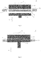
- the vibration welding device 1 comprises a first tool being an upper tool 10 with a vibration welding head which is arranged at a first support.
- the vibration welding head of the upper tool 10 defines a vibration welding or first plane and oscillates or vibrates at least along a first axis X in use.
- an upper tool 10 having a vibration welding head which vibrates in the first plane only along one axis, i.e. the first axis X
- an upper tool having an orbital vibration welding head it is also possible to use an upper tool having an orbital vibration welding head.
- the vibration welding head would perform a circular movement in the first plane, which can be described by means of the first axis X and the further axis Y, being perpendicular to the first axis X.
- the vibration welding device 1 comprises also a second tool being a lower tool 12 which is arranged at a second support.
- the first and the second support and, thus, the upper 10 and the lower tool 12 are movable with respect to each other at least along a second axis Z.
- the second axis Z is perpendicular to the first plane.
- the first support of the vibration welding device 1 is an upper mounting plate and the second support is a lifting table, preferably a lifting table driven by an electric motor or by hydraulics.
- a precise control can be realized which facilitates the vibration welding method.
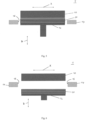
- the vibration welding device 1 has a clamping arrangement comprising at least two oppositely arranged clamping devices 14. Each clamping device 14 provides a clamping surface 16. In the embodiment shown, the clamping arrangement is fastened to a frame (not shown). Thus, it does not automatically move with the first or second support. For an easier understanding, the so constructed vibration welding device 1 will be explained during use.
- the upper 10 and the lower tool 12 and, thus, the first and the second support are in an initial position in which they are sufficiently spaced from each other such that a user may place a first component 3 on a second component or a stack of welded components 5.
- a stack of two welded components 5 is present in the lower tool 12.
- the first component 3 has been placed on the stack of welded components 5 in the lower tool.
- the clamping surfaces 16 of the clamping devices 14 of the clamping arrangement are in an open position.
- the second support and, thus, the lower tool 12 is moved along the second axis Z in the direction of the upper tool 10 until a transfer position is reached.
- the first component 3 is received by the upper tool 10.
- the first component 3 is held in the upper tool 10 by an underpressure or the like.
- the upper tool 10 serves for receiving the first component 3
- the lower tool 12 serves for receiving the second component or the stack of welded components 5.
- the clamping surfaces 16 are still in the open position. This state can be seen in figure 2 .
- the lower tool 12 as well as the second support are moved away from the upper tool 10 along the second axis Z into an intermediate position.
- the first component 3 is directly arranged in the upper tool 10, for example manually or by means of a further device, a movement of the lower tool 12 to the intermediate position is not required.
- the vibration welding device 1 comprises also a generally optional preheating arrangement 18, the lower tool 12 and, thus, the second support, is nonetheless moved into the intermediate position. Thereafter, the preheating arrangement 18 is moved from a parking position into a preheating position between the upper 10 and the lower tool 12, which are in the intermediate position.
- Figure 3 illustrates this stage of the process. As can be seen, the position of the clamping surfaces 16 is unchanged so that they are in the open position.
- the preheating arrangement 18 is moved from the preheating position back into the parking position.
- preheating arrangements for example with IR radiators, as well as their construction are generally known, they are not described in detail herein.
- the lower tool 12 can be moved relative to the upper tool 10 into a vibration welding position. In this position, the first component 3 and the stack of welded components 5 abut each other, as can be seen in figure 4 .
- the two oppositely arranged clamping surfaces 16 have been moved relative to each other along the first axis X such that they directly abut and clamp the stack of welded components 5 arranged in the lower tool 12.
- the clamping arrangement has been moved from the open position into a clamping position in which a movement of the stack of welded components 5 is hindered or prevented during vibration welding at least along the first axis X.
- the movement of the stack of welded components 5 with the first component 3 is at least reduced to such an extent, if not eliminated, that a weld seam of the desired quality results.
- the clamping arrangement of the vibration welding device is fixed to the frame of the vibration welding device.
- the position of the clamping surfaces of the clamping arrangement along the second axis Z is predetermined and adapted to a specific first component 3.
- the clamping device 14 may be fixed to the second support. In this case, the clamping device and, thus, the clamping arrangement, is moved together with the second support.
- the clamping arrangement may be adapted such that it is only used in case the stack of welded components 5 has already a specific height.
- a movability of the clamping surfaces 16 along the second axis Z may be provided additionally. Particularly the movability of the clamping surfaces 16, preferably of each clamping surface 16, along the second axis Z is preferred and advantageous. The latter will be discussed with respect to the second embodiment of the vibration welding device 100.
- the advantage of a fastening of the clamping arrangement at the second support is that the clamping arrangement is moved along the second axis Z together with the second support, in particular the lifting table. This increases the flexibility of the vibration welding device 1.
- the vibration welding device 1 may be adapted to the processing of other components without requiring a removing and refastening of the clamping arrangement in a new position at the frame.
- the two oppositely arranged clamping devices 14 can work with trigger force to find the position of the stack of welded components 5 instead of approaching the clamping position as fixed position.
- the clamping position may be either a position in which the clamping surfaces 16 are in direct abutment with the second component or the stack of welded components 5 or in which the clamping surfaces 16 are offset from the second component or the stack of welded components 5 by a short distance, for example, 0.2 mm. In each case, the clamping surfaces 16 are preferably locked.
- clamping surfaces 16 are offset by a short distance, no additional stress is introduced specifically into the stack of welded components 5 during vibration welding. Further, the stack of welded components 5 is also not moved by the clamping arrangement, in particular by the clamping surfaces 16 of the clamping devices 14. Finally, it has to be noted that the clamping surfaces 16 of the clamping devices 14 can be used for each layer of the stack of welded components 5 or, preferably, mainly in the area or portion in which the self-resonance frequency occurs.
- the upper tool 10 is moved preferably only along the first axis X. Due to the clamping surfaces 16 of the clamping devices 14, a movement of the stack of welded components 5 along this axis X is hindered or prevented, as described above.
- the upper tool 10 is an orbital welding tool so that a movement is performed not only along the first axis X but in the vibration welding plane or first plane
- the further clamping devices 14 are arranged opposite to each other and such that they hinder or prevent a movement of the second component or the stack of welded components 5 at least along an axis Y perpendicular to the first axis X but in the first plane.
- the respective axis Y is also called the third axis Y.
- the clamping surfaces 16 are moved from the clamping position to the open position, and the second support with the second tool, i.e. the lower tool 12, having the increased stack of welded components 20 is moved to the initial position. This can be seen in figure 6 .
- the above steps are repeated by arranging another first component 3 in the first tool, i.e. the upper tool 10.
- the increased stack of welded components 20 being present in the lower tool 12 forms, thus, the new stack of welded components 5.
- the user can remove the resulting or final stack of welded components 5 from the vibration welding device 1.
- the stack of welded components 5 is increased in each cycle by a further component 3 or layer, preferably made of plastic.
- the movement of the first and the second support relative to each other must be controlled very precisely as the vibration welding position, i.e. the distance between the first and second support, must be adjusted for each new cycle.
- the vibration welding position which is approached by the second support i.e. the lifting table
- the stack of two components is present in the lower tool, i.e. the increased stack of welded components 20.
- another first component 3 shall be welded to the increased stack of welded components 20, which forms in this new cycle the second component or the stack of welded components 5.
- the vibration welding position from the beginning cannot be used as the distance between the first and the second support would be too small.
- the vibration welding position must be adjusted in each cycle by the thickness of the added component 3.
- the distance between the first and the second support along the second axis Z must be increased accordingly.
- One advantage of the inventive vibration welding device 1 is that the stress to the weld seams being already present in the stack of welded components 5 is reduced during vibration welding.
- a further advantage is that the oscillation of the vibration welding head and, thus, the first component 3, can be kept constant and out of the self-resonance frequency.
- the vibration cycle time can be kept constant so that the processing time is not increased.
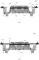
- FIG. 7 to 9 an alternative embodiment of an inventive vibration welding device 100 is shown.
- the construction of the vibration welding device 100 is similar to the above-described vibration welding device 1.
- the clamping surfaces 116 of the clamping devices 114 are additionally movable along the second axis Z. This applies regardless of whether the clamping devices 114 are fastened at the frame or at the second support.
- this movability allows in a particular preferred implementation also a moving of the clamping surfaces 116 along the Z-axis during and/or after vibration welding. Due to this, in particular the stack of welded components 105 is stabilized during the phase after vibration welding in which a force is applied onto the components 103, 105 for creating a reliable welding connection.
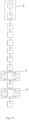
- a first step A an arranging of the first component 3; 103 in the first tool takes place. This can be performed directly by the user.
- this step A of arranging the first component 3; 103 in the first tool comprises the steps A1 and A2.
- the first component 3; 103 is arranged in the second tool, preferably on the second component or on the stack of welded components 5; 105.
- the second support 109 with the first component 3; 103 is moved relative to the first support 107 along the second axis Z from the initial position to a transfer position.
- the user places the first component 3; 103 on the second tool, which is then moved for transferring the first component 3; 103 to the first tool. This eliminates the manual step of arranging the first component 3; 103 in the first tool.
- step H the second support 109 is moved relative to the first support 107 into an intermediate position.
- This step may also be performed independently from the presence of a preheating arrangement 18 for checking that the first component 3; 103 is securely retained in the first tool, i.e. the upper tool 10; 110.
- the preheating arrangement 18 is moved in step I from a parking position into a preheating position between the first and the second tool.
- step J a preheating of the first component 3; 103 and of the second component or the stack of welded components 5; 105 takes place.
- step K the preheating arrangement is moved in step K from the preheating position into the parking position.
- the second support 109 with the second component or the stack of welded components 5; 105 is moved in step B relative to the first support 107 along the second axis Z to the vibration welding position.
- the optional step G may be performed in the vibration welding position, in which the first component 3; 103 and the second component or the stack of welded components 5; 105 are in abutment.
- a requirement for this step is that the clamping surface 16; 116 of at least one, preferably each, clamping device 14; 114 is movable along the second axis Z. This movement is independent from a fixation of the clamping devices 14; 114 at the frame or the second support 109, i.e. independent from a movement of the clamping arrangement with the second support 109, for example.
- step G a moving of the clamping surface 16; 116 of one, two or preferably each clamping device 14; 114 along the second axis Z is performed such that an end of the respective clamping surface 116 adjacent to the upper tool 10; 110 is arranged in a clamping position at or adjacent to an end of the second component or of the stack of welded components 5; 105 abutting the first component 3; 103.
- This is shown, for example, in figures 4 , 8 and 9 .
- the clamping surfaces 16; 116 abut at the stack of welded components 5; 105 directly adjacent to the first component 3; 103. This stabilizes the stack of components 5; 105 in an effective manner without hindering a movement of the first component 3; 103 during vibration welding.
- the clamping surfaces 16; 116 can be used for each layer of the stack of welded components 5; 105 or, preferably, mainly in the area or portion in which the self-resonance frequency occurs.
- the position of the clamping surfaces 16; 116 can be adapted in an easy manner to the thickness of the first component 3; 103.
- step C After the position of the clamping surfaces 16; 116 along the second axis Z has been adjusted, a moving of the clamping surfaces 16; 116 of at least two oppositely arranged clamping devices 14; 114 along the first axis X into the clamping position is performed in step C. As a result, a movement of the second component or of the stack of welded components 5; 105 is hindered at least along the first axis X.
- step C is comprised in particular of the steps C1 and C2.
- step C1 a moving of the first clamping surface 16; 116 in a first direction along the first axis X takes place while before, after or at the same time with step C1 a moving of the oppositely arranged second clamping surface 16; 116 in a second direction opposite to the first direction along the first axis X is performed in step C2.
- two further clamping devices are present which are arranged oppositely to each other and the clamping surfaces 16; 116 of which are moveable along the third axis Y, see above, the movement thereof is performed analogously for stabilizing the stack of welded components 5; 105 additionally.
- the vibration welding device comprises an orbital vibration welding head.
- the oppositely arranged clamping devices 14; 114 can also work with trigger force to find the position of the stack of welded components 5; 105.
- the clamping position is a position in which the clamping surfaces 16; 116 are in direct abutment with the second component or the stack of welded components 5; 105.
- the clamping position is a position in which the clamping surfaces 16; 116 are offset from the second component or the stack of welded components 5; 105 by a short distance, for example, 0.2 mm. In each case, the clamping surfaces 16; 116 are preferably locked in the clamping position.
- a vibration welding of the first component 3; 103 to the second component or to the stack of welded components 5; 105 is performed in step D.
- an increased stack of welded components 20 is, thus, present.
- a force is applied to the increased stack of welded components 20 so that a reliable welding connection results. In particular, waiting a predetermined holding time under application of the force allows for material recrystallisation of the components 3, 5; 103, 105.
- step E a moving of the clamping surfaces 16; 116 along the first axis X into an open position takes place.
- step E may also comprise the two steps E1 and E2.
- a moving of the first clamping surface 16; 116 in the second direction along the first axis X is performed while before, after or at the same time in step E2 a moving of the oppositely arranged second clamping surface 16; 116 in the first direction opposite to the second direction along the first axis X takes place.
- the second support 109 is moved back to the initial position in step F.
- the above-described method steps may be repeated until the resulting stack of components 20 has reached a desired height or number of layers.
- the new height of the stack of welded components 5; 105 has to be considered when approaching the respective positions.
- An embodiment of an inventive retrofitting kit for a vibration welding device having a vibration welding head which vibrates during use in a first plane, preferably only along a first axis, comprises a clamping arrangement having at least two clamping devices 14; 114, each having a clamping surface 16; 116 which is moveable along the first axis X between a clamping position and an open position so that in the clamping position a movement of the second component or the stack of welded components 5; 105 at least along the first axis X can be hindered during vibration welding. Further, at least one clamping surface 16; 116 is preferably movable along the second axis Z being perpendicular to the first plane.
- a common vibration welding device can be equipped with the clamping arrangement so that, after adapting the control method, the vibration welding device realizes the technical effects and advantages of the above-described inventive vibration welding device 1; 100.
- step i an inventive retrofitting kit is provided in step i.
- the clamping devices 14; 114 are fastened in step ii at a lifting table or a frame of the vibration welding device such that the clamping surfaces 16; 116 are arranged opposite to each other.
- step iii an implementing of the clamping device 14; 114 in the control method of the vibration welding device is performed. Consequently, by means of the retrofitting method a common vibration welding device can be improved so that it realizes the technical effects and advantages of the above-described inventive vibration welding device 1; 100.
Landscapes
- Engineering & Computer Science (AREA)
- Mechanical Engineering (AREA)
- Physics & Mathematics (AREA)
- Electromagnetism (AREA)
- Thermal Sciences (AREA)
- Health & Medical Sciences (AREA)
- Toxicology (AREA)
- Lining Or Joining Of Plastics Or The Like (AREA)
Priority Applications (8)
| Application Number | Priority Date | Filing Date | Title |
|---|---|---|---|
| EP21195906.9A EP4147860A1 (en) | 2021-09-10 | 2021-09-10 | Vibration welding device and vibration welding method |
| JP2022112970A JP7470743B2 (ja) | 2021-09-10 | 2022-07-14 | 振動溶着装置および振動溶着方法 |
| US17/879,040 US12145325B2 (en) | 2021-09-10 | 2022-08-02 | Vibration welding device and vibration welding method |
| CN202210950420.0A CN115782186A (zh) | 2021-09-10 | 2022-08-09 | 振动焊接设备以及振动焊接方法 |
| KR1020220107406A KR102981242B1 (ko) | 2021-09-10 | 2022-08-26 | 진동 용접 장치 및 진동 용접 방법 |
| JP2024061865A JP2024074943A (ja) | 2021-09-10 | 2024-04-08 | 振動溶着装置および振動溶着方法 |
| US18/914,760 US12447696B2 (en) | 2021-09-10 | 2024-10-14 | Vibration welding device and vibration welding method |
| JP2025072191A JP2025109207A (ja) | 2021-09-10 | 2025-04-24 | 振動溶着装置および振動溶着方法 |
Applications Claiming Priority (1)
| Application Number | Priority Date | Filing Date | Title |
|---|---|---|---|
| EP21195906.9A EP4147860A1 (en) | 2021-09-10 | 2021-09-10 | Vibration welding device and vibration welding method |
Publications (1)
| Publication Number | Publication Date |
|---|---|
| EP4147860A1 true EP4147860A1 (en) | 2023-03-15 |
Family
ID=77710609
Family Applications (1)
| Application Number | Title | Priority Date | Filing Date |
|---|---|---|---|
| EP21195906.9A Pending EP4147860A1 (en) | 2021-09-10 | 2021-09-10 | Vibration welding device and vibration welding method |
Country Status (5)
| Country | Link |
|---|---|
| US (2) | US12145325B2 (cg-RX-API-DMAC7.html) |
| EP (1) | EP4147860A1 (cg-RX-API-DMAC7.html) |
| JP (3) | JP7470743B2 (cg-RX-API-DMAC7.html) |
| KR (1) | KR102981242B1 (cg-RX-API-DMAC7.html) |
| CN (1) | CN115782186A (cg-RX-API-DMAC7.html) |
Families Citing this family (1)
| Publication number | Priority date | Publication date | Assignee | Title |
|---|---|---|---|---|
| EP4147860A1 (en) * | 2021-09-10 | 2023-03-15 | Branson Ultraschall Niederlassung der Emerson Technologies GmbH & Co. oHG | Vibration welding device and vibration welding method |
Citations (5)
| Publication number | Priority date | Publication date | Assignee | Title |
|---|---|---|---|---|
| JPH08132528A (ja) * | 1994-11-09 | 1996-05-28 | Toyota Motor Corp | 樹脂製品の製造方法及び樹脂製品の振動溶着金型 |
| WO2001074567A1 (de) * | 2000-04-04 | 2001-10-11 | Daimlerchrysler Ag | Verfahren zum positionieren und fixieren von bauteilen |
| EP2837492A1 (de) | 2013-08-14 | 2015-02-18 | Branson Ultraschall Niederlassung der Emerson Technologies GmbH & Co. oHG | Vibrationsschweißanlage mit Hub-, Schiebe- und Kipptisch sowie Steuerverfahren hierfür |
| EP3009254A2 (de) | 2014-10-17 | 2016-04-20 | Branson Ultraschall Niederlassung der Emerson Technologies GmbH & Co. oHG | Kunststoff-vorwärmanordnung für eine kunststoffschweissvorrichtung, kunststoffschweissvorrichtung sowie vorwärmverfahren für ein bauteil |
| EP3020532A1 (de) | 2014-11-12 | 2016-05-18 | Branson Ultraschall Niederlassung der Emerson Technologies GmbH & Co. oHG | Kunststoffschweissvorrichtung sowie dazugehöriges kunststoffschweissverfahren |
Family Cites Families (20)
| Publication number | Priority date | Publication date | Assignee | Title |
|---|---|---|---|---|
| US4352711A (en) * | 1981-06-15 | 1982-10-05 | Branson Ultrasonics Corporation | Friction welding apparatus |
| SU1563914A1 (ru) * | 1988-01-05 | 1990-05-15 | Предприятие П/Я А-3881 | Способ широкослойной наплавки алюминиевой бронзы на низколегированную сталь |
| JPH09254926A (ja) * | 1996-03-21 | 1997-09-30 | Techno Oote:Kk | 積層板材の搬送装置 |
| JP3763194B2 (ja) * | 1997-10-20 | 2006-04-05 | 日産自動車株式会社 | 溶接部品の機械加工装置 |
| JP2000218697A (ja) * | 1999-02-01 | 2000-08-08 | Nichias Corp | ふっ素樹脂製部材の接合方法 |
| DE19938099A1 (de) * | 1999-08-12 | 2001-02-15 | Exama Maschinen Gmbh | Mehrkopf-Reibschweissverfahren und Vorrichtung zur Durchführung des Verfahrens |
| US6814823B1 (en) * | 1999-09-16 | 2004-11-09 | Solidica, Inc. | Object consolidation through sequential material deposition |
| JP3392803B2 (ja) * | 2000-03-14 | 2003-03-31 | 八千代工業株式会社 | 振動溶着装置 |
| DE10332824A1 (de) * | 2003-07-18 | 2005-02-10 | Multi Orbital Systems Gmbh | Mehrkopf-Reibschweißverfahren und Vorrichtung zur Durchführung des Verfahrens |
| US7520308B2 (en) * | 2005-04-04 | 2009-04-21 | Rockwell Automation Technologies, Inc. | Drive unit for controlling reciprocating electromagnets |
| JP2007098589A (ja) * | 2005-09-30 | 2007-04-19 | Toyoda Gosei Co Ltd | 樹脂接合材の製造方法 |
| JP4821996B2 (ja) * | 2006-10-03 | 2011-11-24 | 宇部興産株式会社 | 振動溶着用部品保持装置、振動溶着装置および振動溶着品の製造方法 |
| JP5108815B2 (ja) * | 2009-03-27 | 2012-12-26 | 東海テクノ株式会社 | 摩擦肉盛方法 |
| KR101417460B1 (ko) * | 2012-12-11 | 2014-07-10 | 현대자동차주식회사 | 연료전지용 매니폴드 제조방법 |
| US10150178B2 (en) * | 2016-11-07 | 2018-12-11 | GM Global Technology Operations LLC | Method and apparatus for vibration welding |
| JP6945223B2 (ja) * | 2017-06-29 | 2021-10-06 | 株式会社アルテクス | 接合用共振器又は接合用受け治具 |
| EP3608086B1 (en) * | 2018-08-10 | 2023-09-27 | MARELLI AUTOMOTIVE LIGHTING ITALY S.p.A. | Machine for welding workpieces made of plastic materials |
| CN208800959U (zh) * | 2018-08-29 | 2019-04-30 | 广州市诚涛机械有限公司 | 一种汽车通风阀振动摩擦焊接夹具 |
| JP7180553B2 (ja) * | 2019-06-21 | 2022-11-30 | トヨタ紡織株式会社 | 振動溶着装置 |
| EP4147860A1 (en) * | 2021-09-10 | 2023-03-15 | Branson Ultraschall Niederlassung der Emerson Technologies GmbH & Co. oHG | Vibration welding device and vibration welding method |
-
2021
- 2021-09-10 EP EP21195906.9A patent/EP4147860A1/en active Pending
-
2022
- 2022-07-14 JP JP2022112970A patent/JP7470743B2/ja active Active
- 2022-08-02 US US17/879,040 patent/US12145325B2/en active Active
- 2022-08-09 CN CN202210950420.0A patent/CN115782186A/zh active Pending
- 2022-08-26 KR KR1020220107406A patent/KR102981242B1/ko active Active
-
2024
- 2024-04-08 JP JP2024061865A patent/JP2024074943A/ja active Pending
- 2024-10-14 US US18/914,760 patent/US12447696B2/en active Active
-
2025
- 2025-04-24 JP JP2025072191A patent/JP2025109207A/ja active Pending
Patent Citations (5)
| Publication number | Priority date | Publication date | Assignee | Title |
|---|---|---|---|---|
| JPH08132528A (ja) * | 1994-11-09 | 1996-05-28 | Toyota Motor Corp | 樹脂製品の製造方法及び樹脂製品の振動溶着金型 |
| WO2001074567A1 (de) * | 2000-04-04 | 2001-10-11 | Daimlerchrysler Ag | Verfahren zum positionieren und fixieren von bauteilen |
| EP2837492A1 (de) | 2013-08-14 | 2015-02-18 | Branson Ultraschall Niederlassung der Emerson Technologies GmbH & Co. oHG | Vibrationsschweißanlage mit Hub-, Schiebe- und Kipptisch sowie Steuerverfahren hierfür |
| EP3009254A2 (de) | 2014-10-17 | 2016-04-20 | Branson Ultraschall Niederlassung der Emerson Technologies GmbH & Co. oHG | Kunststoff-vorwärmanordnung für eine kunststoffschweissvorrichtung, kunststoffschweissvorrichtung sowie vorwärmverfahren für ein bauteil |
| EP3020532A1 (de) | 2014-11-12 | 2016-05-18 | Branson Ultraschall Niederlassung der Emerson Technologies GmbH & Co. oHG | Kunststoffschweissvorrichtung sowie dazugehöriges kunststoffschweissverfahren |
Also Published As
| Publication number | Publication date |
|---|---|
| CN115782186A (zh) | 2023-03-14 |
| US12145325B2 (en) | 2024-11-19 |
| JP2023040999A (ja) | 2023-03-23 |
| US20250033297A1 (en) | 2025-01-30 |
| JP7470743B2 (ja) | 2024-04-18 |
| US12447696B2 (en) | 2025-10-21 |
| JP2025109207A (ja) | 2025-07-24 |
| KR102981242B1 (ko) | 2026-06-22 |
| KR20230038092A (ko) | 2023-03-17 |
| JP2024074943A (ja) | 2024-05-31 |
| US20230081335A1 (en) | 2023-03-16 |
Similar Documents
| Publication | Publication Date | Title |
|---|---|---|
| CN114616075B (zh) | 用于在剪切和焊接操作期间支承坯件的夹具组件 | |
| US5023427A (en) | Method and apparatus for automatically aligning proximal edges of sheets to be butt welded | |
| EP1302271B1 (en) | A method for ultrasonic welding stacked materials | |
| US12447696B2 (en) | Vibration welding device and vibration welding method | |
| KR20140044330A (ko) | 맞춤형 시트 금속 스트립 또는 금속 프로파일을 제조하기 위한 장치 및 방법 | |
| EP2272620A1 (de) | Verfahren zum Herstellen einer Fügeverbindung zwischen Teilen in einer Fertigungsanlage | |
| US7237309B2 (en) | Milling machine for longitudinal profiled elements | |
| CN117157167A (zh) | 用于将多个坯件焊接成部件的系统 | |
| KR102728120B1 (ko) | 클램핑 장치를 이용한 다이아몬드 톱날의 레이저용접 시스템 | |
| JP2004130501A (ja) | 加工システム | |
| JP2000334598A (ja) | 建物ユニット用ダイアフラムと梁との溶接用補助装置 | |
| JP2003275883A (ja) | 板材の突き合わせ接合方法 | |
| JPH0924474A (ja) | スポット溶接装置 | |
| JP3488944B2 (ja) | ブランク材の突き合わせ位置決め装置及びブランク材の突き合わせ位置決め方法 | |
| JP2001225242A (ja) | 加工治具 | |
| US4999476A (en) | Machine for pressure welding workpieces heated with arc moving in magnetic field | |
| KR102119629B1 (ko) | 머플러 행거 앗세이 조립 시스템 | |
| KR102104892B1 (ko) | 머플러 행거 앗세이 조립 시스템용 파트 공급장치 | |
| JP3488946B2 (ja) | ブランク材の突き合わせ位置決め装置 | |
| JPS6363577A (ja) | 自動車車体の溶接方法 | |
| US20020185208A1 (en) | Method and apparatus for performing multiple welding operations within one weld fixture assembly | |
| JPH081380A (ja) | 溶接装置と、開先部位置合わせ機構および位置合わせ方法 | |
| JP2776389B2 (ja) | 板材加工機の加工範囲変更方法、及びその装置 | |
| KR102180103B1 (ko) | 언발란스 제품 가공방법 및 가공용 지그 | |
| JPH0550292A (ja) | 自動溶接装置 |
Legal Events
| Date | Code | Title | Description |
|---|---|---|---|
| PUAI | Public reference made under article 153(3) epc to a published international application that has entered the european phase |
Free format text: ORIGINAL CODE: 0009012 |
|
| STAA | Information on the status of an ep patent application or granted ep patent |
Free format text: STATUS: REQUEST FOR EXAMINATION WAS MADE |
|
| 17P | Request for examination filed |
Effective date: 20221116 |
|
| AK | Designated contracting states |
Kind code of ref document: A1 Designated state(s): AL AT BE BG CH CY CZ DE DK EE ES FI FR GB GR HR HU IE IS IT LI LT LU LV MC MK MT NL NO PL PT RO RS SE SI SK SM TR |
|
| P01 | Opt-out of the competence of the unified patent court (upc) registered |
Effective date: 20230601 |
|
| STAA | Information on the status of an ep patent application or granted ep patent |
Free format text: STATUS: EXAMINATION IS IN PROGRESS |
|
| 17Q | First examination report despatched |
Effective date: 20241218 |