EP4147753A1 - Löschflugzeug - Google Patents
Löschflugzeug Download PDFInfo
- Publication number
- EP4147753A1 EP4147753A1 EP22191707.3A EP22191707A EP4147753A1 EP 4147753 A1 EP4147753 A1 EP 4147753A1 EP 22191707 A EP22191707 A EP 22191707A EP 4147753 A1 EP4147753 A1 EP 4147753A1
- Authority
- EP
- European Patent Office
- Prior art keywords
- extinguishing agent
- aircraft
- agent container
- fire
- tailgate
- Prior art date
- Legal status (The legal status is an assumption and is not a legal conclusion. Google has not performed a legal analysis and makes no representation as to the accuracy of the status listed.)
- Granted
Links
Images


Classifications
-
- A—HUMAN NECESSITIES
- A62—LIFE-SAVING; FIRE-FIGHTING
- A62C—FIRE-FIGHTING
- A62C3/00—Fire prevention, containment or extinguishing specially adapted for particular objects or places
- A62C3/02—Fire prevention, containment or extinguishing specially adapted for particular objects or places for area conflagrations, e.g. forest fires, subterranean fires
- A62C3/0228—Fire prevention, containment or extinguishing specially adapted for particular objects or places for area conflagrations, e.g. forest fires, subterranean fires with delivery of fire extinguishing material by air or aircraft
- A62C3/0242—Fire prevention, containment or extinguishing specially adapted for particular objects or places for area conflagrations, e.g. forest fires, subterranean fires with delivery of fire extinguishing material by air or aircraft by spraying extinguishants from the aircraft
-
- B—PERFORMING OPERATIONS; TRANSPORTING
- B64—AIRCRAFT; AVIATION; COSMONAUTICS
- B64D—EQUIPMENT FOR FITTING IN OR TO AIRCRAFT; FLIGHT SUITS; PARACHUTES; ARRANGEMENT OR MOUNTING OF POWER PLANTS OR PROPULSION TRANSMISSIONS IN AIRCRAFT
- B64D1/00—Dropping, ejecting, releasing or receiving articles, liquids, or the like, in flight
- B64D1/16—Dropping or releasing powdered, liquid, or gaseous matter, e.g. for fire-fighting
Definitions
- the invention relates to a fire-fighting aircraft, in particular for fighting forest and bush fires.
- the invention also relates to a method for manufacturing a fire-fighting aircraft and a method for operating a fire-fighting aircraft.
- the invention also relates to an extinguishing agent container for use in a transport aircraft.
- fire-fighting aircraft are not operational to a certain extent. It is therefore desirable to increase the availability and/or reliability of firefighting aircraft.
- a particularly modular concept is proposed, according to which cargo planes, transport planes, planes intended for the transport of troops and military equipment (for example armored vehicles, tracked vehicles, helicopters, UNV drones) are used for different missions can.
- the DE2619350C2 discloses a device for extinguishing fires from the air using a transport aircraft with a tailgate, in which there are one or more containers for the extinguishing agent and which can accommodate at least one extinguishing agent kit, the extinguishing agent container being inclined at an angle of 10 to It is arranged sloping backwards by 15 degrees and is adapted to the usual air cargo containers with regard to the lashing devices and includes a discharge device which consists of a discharge pipe with a valve which is pivotably connected to the extinguishing agent container in the area of the tailgate.
- the drain pipe is connected to the tailgate of the transport aircraft in such a way that when the tailgate is opened into the position, the drain pipe is pivoted downward at the same time.
- the valve of the drain pipe is designed as a quick release valve and is located in the area between the drain pipe and the extinguishing agent container, with the quick release valve being a flap valve which, when opened, suddenly releases the entire outlet cross section.
- the invention relates to an extinguishing agent container for use in a transport aircraft, the extinguishing agent container comprising several sections whose water is or can be poured out of the aircraft onto a fire one after the other and/or the extinguishing agent container comprising a lock and a storage area.
- the aircraft can be used as a fire-fighting aircraft.
- the container advantageously comprises several sections whose water is successively poured onto a fire from the aircraft.
- the extinguishing agent container includes an outlet channel, with the lock being arranged between the outlet channel and the storage area.
- a lockable outlet flap is arranged between the outlet channel and the sluice and/or on a side of the sluice facing away from the storage area.
- a partition with a partition opening is arranged between the storage area and the sluice, it being provided in particular that the partition opening can be closed by means of a slide.
- the extinguishing agent container has an (at least approximately) cylindrical shape.
- the extinguishing agent container can also take any other form that is suitable for transporting the required quantity of extinguishing agent or extinguishing water.
- the diameter of the lockable outlet flap and/or the extinguishing agent container is at least 150 cm, in particular at least 160 cm, for example 170 cm. It is envisaged that the The diameter of the lockable outlet flap and/or the extinguishing agent container is no more than 250 cm, in particular no more than 200 cm.
- the extinguishing agent container or a kit for assembling the extinguishing agent container has a container diameter of 170 cm for 20 m3 (20 cubic meters) of extinguishing agent or extinguishing water.
- the inner surfaces of the container or extinguishing agent container are more affected by the possible sloshing effect and uneven pressure during flight.
- the length of the container or of the extinguishing agent container was increased in an advantageous embodiment and the pressure distribution (of the extinguishing agent or extinguishing water) was thus optimized.
- the storage area has a volume of 15 m3 (15 cubic meters) and the lock has a volume of 5 m3 (15 cubic meters).
- separating walls are arranged as breakwaters at certain intervals.
- the volume of the lock is, for example, at least 2 m3 (2 cubic meters), in particular at least 3 m3 (3 cubic meters).
- the volume in the lock is advantageously limited to 5 m3 (5 cubic meters or 5 tons) of extinguishing agent volume or extinguishing water volume.
- the lockable outlet flap extends (at least essentially) over the entire cross section of the extinguishing agent container. In particular, it is provided that the lockable outlet flap extends (at least essentially) over at least 90% of the cross section of the extinguishing agent container.
- the lockable and openable front cover or outlet flap is designed in such a way that it covers the entire lateral diameter (e.g. 170 cm) as can be opened and closed as shown below.
- the middle cover and the locking mechanism of the outlet flap in the interior of the extinguishing agent container can require an opening area that is reduced compared to the opening area that is possible with the opening and closing mechanism of the outlet flap described below.
- the specified solution or the outlet flap can also be locked and unlocked with flap valve systems and similar mechanisms, which causes the opening area to be limited to up to approximately 90% of the cross-sectional area of the extinguishing agent container.
- the storage area has a volume that corresponds to twice or three times the volume of the lock.
- Volume in this sense is a synonym for capacity.
- the storage area has one or more separating walls, it being provided in particular that the separating wall or the separating walls divides or subdivides the storage area into sections.
- the separating walls or the separating wall has at least one flow opening through which the extinguishing agent or extinguishing water can flow into the adjacent section.
- at least one compensation opening is also provided in a separating wall.
- at least one additional opening is also provided in a separating wall.
- a flow opening of a separation wall is provided in particular in the lower area of the separation wall.
- a compensating opening of a separating wall is provided in particular in the upper area of the separating wall.
- An additional opening of a separating wall is provided in particular in the middle area of the separating wall.
- the extinguishing agent container includes wheels that can be converted from a first state into a second state and/or from the second state into the first state, the extinguishing agent container can be rolled in the first state supported by the wheels, and wherein in the second state the extinguishing agent container rests on a support device and is not supported by the wheels (dolly wheel mechanism, in particular with the use of a spindle as a rotatable arm).
- the agent container wheels (the dolly wheel mechanism) are used when the agent container or kit is loaded onto the aircraft and returned from the aircraft to the transport vehicle.
- the invention also relates to a fire-fighting aircraft, which has a transport aircraft with a tailgate and an extinguishing agent container that can be removed from the transport aircraft via the tailgate (also referred to as a ramp or loading ramp), in particular an extinguishing agent container with one or more of the aforementioned features.
- the extinguishing agent container is placed and/or fixed in the transport aircraft in such a way that extinguishing agent and/or extinguishing water pours out of the lock and/or out of the extinguishing agent container over the opened tailgate (ramp or loading ramp).
- the tailgate is connected to the fuselage of the transport aircraft by means of a hinge, with the extinguishing agent container being placed and/or fixed in the transport aircraft in such a way that the extinguishing agent and/or extinguishing water cannot escape from the lock and/or the extinguishing agent container pours over the hinge and/or an actuator or mechanism for opening or closing the tailgate.
- the invention also relates to a method for producing a fire-fighting aircraft, in particular for producing a fire-fighting aircraft with one or more of the aforementioned features, with the extinguishing agent container being pulled over the opened tailgate by means of a pulling device, for example comprising a winch and/or a cable and/or a steel cable is pulled into or into the cargo hold of the transport aircraft, with the extinguishing agent container on wheels of the extinguishing agent container and/or on the wheels of the extinguishing agent container rolls.
- a pulling device for example comprising a winch and/or a cable and/or a steel cable
- the wheels are in their first state.
- the wheels are converted from their first state to their second state.
- an armored vehicle is fixed in an aircraft or transport aircraft by means of a group of anchors, the fixation being released, the armored vehicle being removed from the aircraft or transport aircraft, with one or the extinguishing agent container for extinguishing water is arranged in the aircraft or transport aircraft, the extinguishing agent container being fixed by means of at least one, in particular at least two, in particular at least three, in particular at least four, in particular at least five, in particular at least all of the group of anchorages.
- the invention also relates to a method for operating a fire-fighting aircraft, in particular for operating a fire-fighting aircraft with one or more of the aforementioned features.
- the extinguishing agent container in the cargo hold of the transport aircraft is advantageously filled with extinguishing agent and/or extinguishing water.
- a tank fire engine is used for this purpose, with extinguishing agent or extinguishing water being filled into the extinguishing agent container from the tank of the tank fire engine. It is advantageously provided that the lock and/or the storage area is or is filled with extinguishing agent or extinguishing water.
- the fire-fighting aircraft transporting the extinguishing agent container filled with extinguishing agent or extinguishing water lifts off the ground of the starting base and flies to the place of use, i.e. the place where the extinguishing agent or extinguishing water is to be used, for example to extinguish a fire .
- the tailgate is opened in an exemplary embodiment.
- the fire-fighting aircraft is aligned in such a way that extinguishing agents or Extinguishing water in the lock presses against the outlet flap.
- the locking of the outlet flap is followed by the slide opening, so that extinguishing agent or extinguishing water can or does flow from the storage area into the lock.
- the fire-fighting aircraft is aligned in particular in such a way that the lock is filled to the desired extent or (almost) completely with extinguishing agent or extinguishing water.
- the partition opening of the partition is closed by means of the slide.
- the site is flown to again.
- a different location can also be flown to.
- the tailgate is opened in an exemplary embodiment.
- the procedure described is repeated.
- the fire-fighting aircraft it is aligned in such a way that the extinguishing agent or extinguishing water in the lock presses against the outlet flap.
- This is unlocked in a further advantageous embodiment of the invention, so that extinguishing agent or extinguishing water presses open the outlet flap, pours out in particular over the outlet channel and the tailgate and leaves the fire-fighting aircraft (and falls on the ground).
- the fire-fighting aircraft are aligned after the lock has been emptied in such a way that the outlet flap closes. In a further advantageous embodiment of the invention, this is locked (in the closed state).
- the tailgate is closed. Locking of the exhaust flap follows opening the slider so that extinguishing agent or extinguishing water can or flows from the storage area into the lock.
- the fire-fighting aircraft is in particular aligned in such a way that the lock is filled to the desired extent or (almost) completely with extinguishing agent or extinguishing water. Thereafter, in a further advantageous embodiment, the partition opening of the partition is closed by means of the slide.
- the site of use is flown to again or to a further or different site.
- the tailgate is opened in an exemplary embodiment.
- the procedure described is repeated.
- the fire-fighting aircraft it is aligned in such a way that the extinguishing agent or extinguishing water in the lock presses against the closed outlet flap.
- This is unlocked in a further advantageous embodiment of the invention, so that extinguishing agent or extinguishing water presses open the outlet flap, pours out in particular over the outlet channel and the tailgate and leaves the fire-fighting aircraft (and falls on the ground).
- the fire-fighting aircraft is aligned after the lock has been (completely or essentially completely) emptied in such a way that the outlet flap closes. In a further advantageous embodiment of the invention, this is locked in the closed state.
- the tailgate is closed.
- the operation is aborted and the fire-fighting aircraft returns to the ground (the starting point) in an advantageous embodiment.
- the slider opens so that extinguishing agent or fire-fighting water can flow from the storage area into the lock.
- the fire-fighting aircraft is aligned in particular in such a way that the lock is filled to the desired extent or almost completely with extinguishing agent or extinguishing water. After that, it will continue to be more beneficial Configuration closed the partition opening of the partition by means of the slide.
- the tailgate is opened and when the place of use is reached, the outlet flap is unlocked again as described, so that extinguishing agent or extinguishing water can leave the fire-fighting aircraft (to fall on the ground).
- the outlet flap can be unlocked and locked manually by means of an actuating lever.
- the slider of the partition wall can be adjusted, in particular manually, by means of a slider actuating element, for example a crank.
- the slider operating member (the crank) and the operating lever are arranged adjacently such that an operator can manually operate both the operating lever and the slider operating member (the crank) from one viewpoint.
- the opening area of the partition wall opening is no more than 40%, in particular no more than 30%, of the cross-sectional area of the extinguishing agent container (for example in the area of the partition wall).
- the opening area of the flow opening is no more than 30%, in particular no more than 20%, in particular no more than 10%, of the cross-sectional area of the extinguishing agent container (for example at the point of the separation wall).
- the separation walls each include a locking mechanism.
- a double-eccentric valve system is used to open the closing mechanism of the separation walls, which changes the diameter of the extinguishing agent or extinguishing water outlet.
- This system can interrupt and open the flow of extinguishing agent or water in the vertical direction. For this purpose, the negative pressure effects during unloading or emptying or emptying of the extinguishing agent container or kit or construction set have been taken into account.
- the extinguishing agent container has an anchor or a coupling element, by means of which the extinguishing agent container is connected to a traction device (cable winch, "hoist”, for example comprising a winch and/or a cable and/or a steel cable) of the transport aircraft can be coupled.
- a traction device such as a winch and/or a cable and/or a steel cable
- the extinguishing agent container is pulled by means of the pulling device (cable winch, "hoist”, for example comprising a winch and/or a cable and/or a steel cable) into or into the cargo hold of the transport aircraft or the fire-fighting aircraft.
- the extinguishing agent container in the transport aircraft or in the or a cargo hold of the transport aircraft (which is a fire-fighting aircraft in the sense of the terminology used here due to the accommodation of the extinguishing container) is fixed in the transport aircraft by means of anchors which are in the transport aircraft, for example for anchoring tracked vehicles.
- center of gravity of the aircraft in the sense of this disclosure, especially when dispensing water for the purpose of extinguishing, is not considered to be moved because the containers are emptied from the inside to the outside via the ramp, for what the aircraft is designed.
- the extinguishing agent container is provided as a kit or as a "plug & play” solution.
- the extinguishing agent container is designed and/or shaped (essentially) cylindrical, (essentially) like a cylinder or (essentially) in the shape of a cylinder.
- the end element of the extinguishing agent container (closes the approximately cylindrical extinguishing agent container on the side opposite the outlet flap) and/or the side wall or the casing of the extinguishing agent container can be made of aluminum, steel or plastic, for example. However, it has proven to be advantageous to make the end element and the side wall or the jacket of the extinguishing agent container from aluminum. It has also proven to be advantageous to make the support devices out of aluminum. In contrast, locking mechanisms and locks are advantageously made of steel.
- the aircraft center of gravity/transport aircraft center of gravity, C. o. G. Center of Gravity
- C. o. G. Center of Gravity
- the extinguishing agent container is fixed with tension belts. It is provided in particular that the tension belts are fastened on the aircraft side to fastening devices in the aircraft floor of the cargo hold of the transport aircraft.
- Aluminum within the meaning of this disclosure is in particular 5182 aluminum.
- a transport aircraft within the meaning of this disclosure is in particular an airplane/transport aircraft with a cargo hold that is accessible via a tailgate.
- a transport aircraft within the meaning of this disclosure is in particular a propeller aircraft. Examples of transport aircraft within the meaning of this disclosure are A400M, C-130, C-125 and CN235.
- Separation walls within the meaning of this disclosure are, in particular, breakwaters.
- Extinguishing media within the meaning of this disclosure is, in particular, extinguishing water.
- FIG. 1 shows a fire-fighting aircraft 100 in an elevation view, the fire-fighting aircraft 100 comprising a transport aircraft 101 in which an extinguishing agent container 1 is arranged, which is visible through the elevation view.
- 2 shows a perspective detail of the fire-fighting aircraft 100 to explain the placement or fixing of the extinguishing agent container 1 in the cargo hold of the transport aircraft 101.
- 3 shows a perspective view of the extinguishing agent container 1
- 4 shows an elevation view of the extinguishing agent container 1.
- the extinguishing agent container 1 has approximately the shape of a cylinder and is made of aluminum.
- the extinguishing agent container 1 is closed at one end by an end element 111 .
- the end element 111 is designed to be approximately circular and has an area which is referred to below as the cross-sectional area of the extinguishing agent container 1 .
- the extinguishing agent container 1 includes an in 6 outlet channel 4, shown separately, a lock 3 and a storage area 2.
- the lock 3 is arranged between the outlet channel 4 and the storage area 2.
- Separation walls 8 are arranged in the storage area 2 and divide the storage area 2 into segments.
- FIG. 1 shows an embodiment of a separating wall 8 which, in the lower area, comprises a flow opening 81 arranged in the lower area of the extinguishing agent container and an equalization opening 82 arranged in the upper area of the extinguishing agent container 1 .
- an additional opening 83, an additional opening 84 and an additional opening 85 are provided in the middle region of the extinguishing agent container 1 (ie between top and bottom).
- the opening area of the flow opening 81 is approximately 4% of the cross-sectional area of the extinguishing agent container 1 (in the area of the separating wall 8).
- Partition wall 6 shown in detail is provided, which has an in 8 base plate 73 shown in detail with a partition opening 7 includes.
- the partition wall opening 7 is closed by means of an in 9 Slider 71 shown in detail can be closed.
- a crank 72 is provided as an actuating element, by means of which a gear wheel 76 can be rotated by means of a shaft 75 .
- the gear wheel 76 meshes with a toothed rack 77 so that the slider 71 can be moved in two directions, up and down, by turning the crank 72.
- the maximum opening area of the partition wall opening 7 is approximately 25% of the cross-sectional area of the extinguishing agent container 1 (in the area of the partition wall 7) and/or the area of a lockable outlet flap 5 described below
- a lockable outlet flap 5 is arranged between the outlet channel 4 and the sluice 3 10 is shown in detail.
- the outlet flap 5 includes a seal 55.
- the outlet flap 5 can be locked and unlocked manually by means of an actuating lever 513.
- the operating lever 513 is part of an in 12 locking and unlocking mechanism 51 shown in detail, which also has a guide element 512 fixed to the outer wall of the extinguishing agent container 1 and a pin 511 .
- the pin 511 is engaged with an in 10 and 11 Locking and unlocking plate 52 shown, which has guide recesses 521. In these guide recesses 521 are not shown pins of designated with reference numeral 54 Locking and unlocking arms 54 arranged.
- the locking and unlocking arms 54 are guided in guide profiles 53 .
- the locking and unlocking plate 52 can be rotated by means of the (manual) actuating lever 513 due to the mechanism described, so that the outlet flap 5 is unlocked or locked depending on the direction of rotation.
- the outlet duct 4 covers (when the extinguishing agent container 1 is fixed in the transport aircraft 101) the hinge 103 of the tailgate 102 of the transport aircraft 101. Covered within the meaning of this disclosure means in particular that no extinguishing agent or extinguishing water flows onto the hinge 103 of the tailgate 102 of the transport plane 101 when the extinguishing agent container 1 or the lock 3 arranged in the fire-fighting aircraft 100 is (at least partially) emptied.
- the outlet flap 5 essentially encompasses the entire cross-sectional area of the extinguishing agent container 1 in the area of the outlet flap 5.
- the extinguishing agent container 1 comprises a water inlet opening 15 in the storage area 2, which is equipped with an in 13 and 14 Closure 16 shown in detail is closable or can be closed.
- the closure 16 has a vent flap 161 and an engagement 162 .
- the sluice 3 comprises a water inlet opening 315 designed to correspond to the water inlet opening 15 and which can be or can be closed with a closure 316 corresponding to the closure 16 .
- the extinguishing agent container 1 comprises an in 15 and 16 shown rolling mechanism 11 with foldable wheels 111 and 112, which can be arranged in two states.
- the extinguishing agent container 1 can roll on the wheels 111 and 112 if the wheels 111 and 112 are in the 15 are shown first state.
- the extinguishing agent container 1 is not supported by the wheels 111 and 112 but by support devices 125, 126, 127, 128 and 129 carried when the wheels 111 and 112 are in the in 16 shown second state are.
- the first state of the wheels 111 and 112 is intended to move the extinguishing agent container as described below with reference to FIG 17 and 18 described to move into the or a cargo hold of the transport aircraft 101.
- the extinguishing agent container 1 comprises at least one coupling element 18, by means of which the extinguishing agent container 1 is connected to a traction device (cable winch, "hoist”, for example comprising a winch and/or a cable and/or a steel cable) of the transport aircraft 101 can be coupled.
- a traction device capable winch, "hoist”, for example comprising a winch and/or a cable and/or a steel cable
- a steel cable 107 which belongs to a winch of the transport aircraft 101, is connected to the coupling element 18 for this purpose.
- the extinguishing agent container 1 is then pulled by a transport vehicle 200 via the tailgate 102 into the cargo hold of the transport aircraft 101 by means of the winch.
- the wheels 111 and 112 of the rolling mechanism 11 are transferred to the second state, so that the extinguishing agent container 1 with the protective devices 125, 126, 127, 128, 129 rests on the aircraft floor of the transport aircraft 101.
- the extinguishing agent container 1 is fixed in the transport aircraft 101 by means of anchors which are provided in the transport aircraft 101, for example for anchoring tracked vehicles.
- tension belts 91 which are fixed to fastening elements 92 in the floor of the cargo hold of the transport aircraft 101 are provided for this purpose and are fixed to the extinguishing agent container 1 so that it is firmly fixed in and on the transport aircraft 101 .
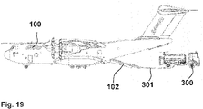
- the present exemplary embodiment provides that extinguishing agent or extinguishing water is introduced into the extinguishing agent container 1 by means of a tank firefighting vehicle 300 via a hose 301 through the water inlet opening 15 or 315 .
- the partition opening 7 is open, so that the lock 3 and/or the storage area 2 are or are filled with extinguishing agent or extinguishing water or can be filled.
- the tailgate 102 of the fire-fighting aircraft 100 is then closed.
- the fire-fighting aircraft 100 takes off from the ground of the starting base and flies to the place of use, ie the place at which the extinguishing agent or extinguishing water is to be used, for example to extinguish a fire.
- the fire-fighting aircraft 100 is aligned in such a way that the extinguishing agent or fire-fighting water in the lock 3 presses on the outlet flap 5 .
- the tailgate 102 is opened. This situation is in 1 shown, the orientation of the fire-fighting aircraft 100 being defined by the angle ⁇ (angle of attack), which in the exemplary embodiment is approximately 8 degrees (8°) (relative to the horizontal).
- the outlet flap 5 is unlocked so that the extinguishing agent or water presses open the outlet flap 5 and in particular pours out via the outlet channel and the tailgate and leaves the fire-fighting aircraft 100 (and falls on the ground).
- the fire-fighting aircraft 100 is aligned in such a way that the outlet flap 5 closes.
- the outlet flap 5 is then locked.
- the slide then opens so that extinguishing agent or extinguishing water can flow from the storage area 2 into the lock 3 .
- the fire-fighting aircraft 100 is in particular aligned in such a way that the lock 3 is filled to the desired extent or almost completely with extinguishing agent or extinguishing water. Thereafter, it is provided in particular that the slider 71 is closed. Then the or another location is flown to. When the desired location is reached, the prescribed procedure is repeated.
- the fire-fighting aircraft 100 is transferred back to a transport aircraft 101 by removing the extinguishing agent container 1 .
- These are, for example, in reverse with reference to 17 and 18 described method to transfer the wheels 111 and 112 of the rolling mechanism 11 from the second state (folded down) to the first state (unfolded) and to detach the extinguishing agent container 1 from the tension belts 91 beforehand. Provision is then made for the extinguishing agent container 1 to be pulled onto the transport vehicle 200 by means of transport means of the transport vehicle 200 which are not shown in detail.
- a particularly reliable and robust extinguishing system for fighting forest and bush fires is provided by means of the invention.
- transport aircraft which typically perform tasks other than forest and bush fire extinguishing, significantly reduces the cost of fighting forest and bush fires and also reduces the complications of using aircraft for several months and/or over a year have not been used for a long period of time.
- large quantities of extinguishing water or extinguishing agent can be deployed in a single firefighting flight.
- extinguishing agent or extinguishing water can be deployed per flight.
- the extinguishing agent container is very robust and does not require any electrical equipment. Rather, the extinguishing agent container can be manually operated mechanically by a single operator without the electrical system failing.
- the extinguishing agent container does not need a safety mechanism that is designed in such a way that it blocks the outlet flap from opening when the slider is not closed and/or not fully closed, and that it Opening of the outlet flap blocked if the slider is not and/or not fully closed.
- the invention enables a firefighting aircraft to be produced from a transport aircraft in less than an hour.
- the almost complete filling of the extinguishing agent container with extinguishing water or extinguishing agent is possible within 10 minutes and less.
- the extinguishing agent container or the kit or the kit is also manufactured under EASA 21G - POA- Production Organization Approval. For all civil aircraft and helicopters.
- the extinguishing agent container or the assembly or the kit will, among other things, obtain EN 9120 certification for military aircraft.
Landscapes
- Engineering & Computer Science (AREA)
- Aviation & Aerospace Engineering (AREA)
- Life Sciences & Earth Sciences (AREA)
- Biodiversity & Conservation Biology (AREA)
- Ecology (AREA)
- Forests & Forestry (AREA)
- Health & Medical Sciences (AREA)
- Public Health (AREA)
- Business, Economics & Management (AREA)
- Emergency Management (AREA)
- Fire-Extinguishing By Fire Departments, And Fire-Extinguishing Equipment And Control Thereof (AREA)
Abstract
Description
- Die Erfindung betrifft ein Löschflugzeug, insbesondere zur Bekämpfung von Wald- und Buschbränden. Die Erfindung betrifft zudem ein Verfahren zum Herstellen eines Löschflugzeugs sowie ein Verfahren zum Betrieb eines Löschflugzeugs. Die Erfindung betrifft weiterhin einen Löschmittelcontainer zur Verwendung in einem Transportflugzeug.
- Es hat sich gezeigt, dass Löschflugzeuge zu einem bestimmten Anteil nicht einsatzfähig sind. Es ist daher wünschenswert, die Verfügbarkeit und/oder die Zuverlässigkeit von Löschflugzeugen zu erhöhen. Es wird dazu ein, insbesondere modulares, Konzept vorgeschlagen, gemäß dem Frachtflugzeuge, Transportflugzeuge, Flugzeuge die für den Transport von Truppen und militärischem Equipment (beispielsweise gepanzerte Fahrzeuge, Ketten-Fahrzeuge, Helikopter, UNV-Drohnen) vorgesehen sind, für unterschiedliche Missionen eingesetzt werden können.
- Die
DE 2619350 C2 offenbart eine Einrichtung zum Löschen von Bränden aus der Luft mittels eines Transportflugzeuges mit Heckladeklappe, in welchem sich ein oder mehrere Behälter für das Löschmittel befinden und welches mindestens einen Löschmittel-Rüstsatz aufnehmen kann, wobei der Löschmittelbehälter mit einem Neigungswinkel gegenüber der horizontalen Flugzeuglängsachse von 10 bis 15 Grad nach hinten abfallend angeordnet und hinsichtlich der Verzurrvorrichtungen den üblichen Luftfrachtbehältern angepasst ist und eine Ablasseinrichtung umfasst, die aus einem Abflussrohr mit Ventil besteht, welches im Bereich der Heckladeklappe schwenkbar mit dem Löschmittelbehälter verbunden ist. Dabei ist das Abflussrohr derart mit der Heckladeklappe des Transportflugzeugs verbunden, dass beim Öffnen der Heckladeklappe in die Stellung gleichzeitig das Abflussrohr nach unten geschwenkt wird. Das Ventil des Abflussrohres ist als Schnellablassventil ausgebildet und im Bereich zwischen Abflussrohr und Löschmittelbehälter angeordnet, wobei das Schnellablassventil ein Klappventil ist, welches beim Öffnen schlagartig den gesamten Auslassquerschnitt freigibt. - Die Erfindung betrifft einen Löschmittelcontainer zur Verwendung in einem Transportflugzeug, wobei der Löschmittelcontainer mehrere Sektionen umfasst, deren Wasser nacheinander aus dem Flugzeug auf einen Brand geschüttet wird bzw. geschüttet werden kann und/oder wobei der Löschmittelcontainer eine Schleuse und einen Vorratsbereich umfasst.
- Es ist ferner beispielsweise vorgesehen, dass dieses Flugzeug (beispielsweise ein Transportflugzeug) ohne Umrüstung am Flugzeug einen Löschcontainer wie nachfolgend ausgestaltet aufnimmt. Mittels dieses Containers ist das Flugzeug als Löschflugzeug einsetzbar. Der Container umfasst vorteilhafterweise mehrere Sektionen, deren Wasser nacheinander aus dem Flugzeug auf einen Brand geschüttet wird.
- In vorteilhafter Ausgestaltung der Erfindung umfasst der Löschmittelcontainer einen Auslasskanal, wobei die Schleuse zwischen dem Auslasskanal und dem Vorratsbereich angeordnet ist. Dabei ist in weiterhin vorteilhafter Ausgestaltung der Erfindung zwischen dem Auslasskanal und der Schleuse und/oder auf einer dem Vorratsbereich abgewandten Seite der Schleuse eine verriegelbare Auslassklappe angeordnet. In weiterhin vorteilhafter Ausgestaltung der Erfindung ist vorgesehen, dass zwischen dem Vorratsbereich und der Schleuse eine Trennwand mit einer Trennwandöffnung angeordnet ist, wobei insbesondere vorgesehen ist, dass die Trennwandöffnung mittels eines Schiebers verschließbar ist.
- Der Löschmittelcontainer hat in besonders vorteilhafter Weise eine (zumindest annähernd) zylinderförmige Form. Der Löschmittelcontainer kann aber auch jede andere Form annehmen die geeignet ist, die erforderlich Menge Löschmittel bzw. Löschwasser zu transportieren.
- In vorteilhafter Ausgestaltung der Erfindung beträgt Durchmesser der verriegelbaren Auslassklappe und/oder des Löschmittelcontainers zumindest 150 cm, insbesondere zumindest 160 cm, zum Beispiel 170 cm. Es ist vorgesehen, dass der Durchmesser der verriegelbaren Auslassklappe und/oder des Löschmittelcontainers nicht mehr als 250 cm, insbesondere nicht mehr als 200 cm beträgt.
- In beispielhafter Ausgestaltung hat der Löschmittelcontainer bzw. ein Kit zum Zusammensetzen des Löschmittelcontainers einen Behälterdurchmesser von 170 cm für 20 m3 (20 Kubikmeter) Löschmittel bzw. Löschwasser. Mit zunehmendem Durchmesser werden die Innenflächen des Behälters bzw. des Löschmittelcontainers stärker durch den möglichen Schwapp-Effekt und ungleichmäßigen Druck während des Fluges beeinträchtigt. Anstatt also den Durchmesser (des Behälters bzw. des Löschmittelcontainers) zu vergrößern, wurde in vorteilhafter Ausgestaltung die Länge des Behälters bzw. des Löschmittelcontainers erhöht und somit die Druckverteilung (des Löschmittels bzw. Löschwassers) optimiert.
- Beispielsweise umfasst der Vorratsbereich ein Volumen von 15 m3 (15 Kubikmetern) und die Schleuse beispielsweise ein Volumen von 5 m3 (15 Kubikmetern). Um ein Schwappen in dem Vorratsbereich des Löschmittelcontainers bzw. des Behälters zu vermeiden bzw. zu verringern sind in bestimmten Abständen Separationswände als Wellenbrecher angeordnet.
- Das Volumen der Schleuse beträgt beispielsweise zumindest 2 m3 (2 Kubikmeter), insbesondere zumindest 3 m3 (3 Kubikmeter). Das Volumen in der Schleuse ist vorteilhafterweise auf 5 m3 (5 Kubikmeter bzw. 5 Tonnen) Löschmittelvolumen bzw. Löschwasservolumen begrenzt.
- Es ist insbesondere vorgesehen, dass sich die verriegelbare Auslassklappe (zumindest im Wesentlichen) über den gesamten Querschnitt des Löschmittelcontainers erstreckt. Es ist insbesondere vorgesehen, dass sich die verriegelbare Auslassklappe (zumindest im Wesentlichen) über mindestens 90 % des Querschnitts des Löschmittelcontainers erstreckt.
- Die abschließbare und zu öffnende Frontabdeckung bzw. Auslassklappe ist so konzipiert, dass sie im gesamten Querdurchmesser (beispielsweise 170 cm) wie unten angegeben geöffnet und geschlossen werden kann. Die mittlere Abdeckung und der Verriegelungsmechanismus der Auslassklappe im Innenraum des Löschmittelcontainers können jedoch eine Öffnungsfläche bedingen, die gegenüber der Öffnungsfläche, die mit der unten beschriebenen Öffnungs- und Schließmechanik der Auslassklappe möglich ist, verringert ist. Die angegebene Lösung bzw. die Auslassklappe kann auch mit Klappenventilsystemen und ähnlichen Mechanismen verriegelt und entriegelt werden, was eine Begrenzung der Öffnungsfläche auf bis zu annähernd 90 % der Querschnittsfläche des Löschmittelcontainers bewirkt.
- Es ist insbesondere vorgesehen, dass der Vorratsbereich ein Volumen umfasst, das dem zweifachen oder dreifachen des Volumens der Schleuse entspricht. Volumen in diesem Sinne ist ein Synonym für Fassungsvermögen.
- In weiterhin vorteilhafter Ausgestaltung der Erfindung weist der Vorratsbereich eine oder mehrere Separationswände auf, wobei insbesondere vorgesehen ist, dass die Separationswand bzw. die Separationswände den Vorratsbereich in Sektionen unterteilt bzw. unterteilen. In weiterhin vorteilhafter Ausgestaltung der Erfindung ist vorgesehen, dass die Separationswände bzw. die Separationswand zumindest eine Flussöffnung aufweist durch die Löschmittel bzw. Löschwasser in die benachbarte Sektion fließen kann. In weiterhin vorteilhafter Ausgestaltung der Erfindung ist zudem in einer Separationswand zumindest eine Ausgleichsöffnung vorgesehen. In weiterhin vorteilhafter Ausgestaltung der Erfindung ist zudem in einer Separationswand zumindest eine Zusatzöffnung vorgesehen. Eine Flussöffnung einer Separationswand ist insbesondere in dem unteren Bereich der Separationswand vorgesehen. Eine Ausgleichseröffnung einer Separationswand ist insbesondere in dem oberen Bereich der Separationswand vorgesehen. Eine Zusatzöffnung einer Separationswand ist insbesondere in dem mittleren Bereich der Separationswand vorgesehen.
- In weiterhin vorteilhafter Ausgestaltung der Erfindung umfasst der Löschmittelcontainer Räder, die von einem ersten Zustand in einen zweiten Zustand und/oder von dem zweiten Zustand in den ersten Zustand überführbar sind, wobei der Löschmittelcontainer in dem ersten Zustand von den Rädern getragen gerollt werden kann, und wobei der Löschmittelcontainer in dem zweiten Zustand auf einer Stützvorrichtung aufliegt und nicht von den Rädern getragen wird (Dolly Radmechanismus, insbesondere mit dem Einsatz einer Spindel als drehbarem Arm). Die Räder des Löschmittelcontainers (der Dolly-Radmechanismus) werden verwendet, wenn der Löschmittelcontainer bzw. das Kit (der Bausatz) in das Flugzeug geladen und vom Flugzeug zum Transportfahrzeug zurückgebracht wird.
- Die Erfindung betrifft weiterhin ein Löschflugzeug, das ein Transportflugzeug mit einer Heckladeklappe und einen über die Heckladeklappe (auch als Rampe bzw. Laderampe bezeichnet) aus dem Transportflugzeug entnehmbaren Löschmittelcontainer, insbesondere einen Löschmittelcontainer mit einem oder mehreren der vorgenannten Merkmale, aufweist.
- In weiterhin vorteilhafter Ausgestaltung der Erfindung ist der Löschmittelcontainer derart in dem Transportflugzeug platziert und/oder fixiert, dass sich Löschmittel und/oder Löschwasser aus der Schleuse und/oder aus dem Löschmittelcontainer über die geöffnete Heckladeklappe (Rampe bzw. Laderampe) ergießt. In weiterhin vorteilhafter Ausgestaltung der Erfindung ist die Heckladeklappe mittels eines Scharniers mit dem Rumpf des Transportflugzeugs verbunden, wobei der Löschmittelcontainer derart in dem Transportflugzeug platziert und/oder fixiert ist, dass sich das Löschmittel und/oder Löschwasser aus der Schleuse und/oder dem Löschmittelcontainer nicht über das Scharnier und/oder einen Aktor oder Mechanismus zum Öffnen bzw. zum Schließen der Heckladeklappe ergießt.
- Die Erfindung betrifft weiterhin ein Verfahren zur Herstellung eines Löschflugzeugs, insbesondere zur Herstellung eines Löschflugzeugs mit einem oder mehreren der vorgenannten Merkmale, wobei der Löschmittelcontainer mittels einer Zugvorrichtung, beispielsweise umfassend eine Winde und/oder ein Seil und/oder ein Stahlseil, über die geöffnete Heckladeklappe in einen oder den Frachtraum des Transportflugzeugs gezogen wird, wobei der Löschmittelcontainer auf Rädern des Löschmittelcontainers und/oder auf den Rädern des Löschmittelcontainers rollt. Dabei sind die Räder in vorteilhafter Ausgestaltung in ihrem ersten Zustand. Wenn der Löschmittelcontainer die gewünschte Position in dem Frachtraum des Transportflugzeugs erreicht hat, werden die Räder von ihrem ersten Zustand in ihren zweiten Zustand überführt.
- Gemäß einem oder dem Verfahren zur Herstellung eines Löschflugzeugs ist ein gepanzertes Fahrzeug mittels einer Gruppe von Verankerungen in einem Flugzeug bzw. Transportflugzeug fixiert, wobei die Fixierung gelöst wird, wobei das gepanzerte Fahrzeug aus dem Flugzeug bzw. Transportflugzeug entfernt wird, wobei ein oder der Löschmittelcontainer für Löschwasser in dem Flugzeug bzw. Transportflugzeug angeordnet wird, wobei der Löschmittelcontainer mittels zumindest einer, insbesondere zumindest zweier, insbesondere zumindest dreier, insbesondere zumindest vier, insbesondere zumindest fünf, insbesondere zumindest aller, der Gruppe der Verankerungen fixiert wird.
- Die Erfindung betrifft weiterhin ein Verfahren zum Betrieb eines Löschflugzeugs, insbesondere zum Betrieb eines Löschflugzeugs mit einem oder mehreren der vorgenannten Merkmale. Dabei wird zunächst vorteilhafter Weise der Löschmittelcontainer im Frachtraum des Transportflugzeugs mit Löschmittel und/oder Löschwasser gefüllt. Dazu wird in vorteilhafter Ausgestaltung ein Tanklöschfahrzeug verwendet, wobei aus dem Tank des Tanklöschfahrzeugs Löschmittel bzw. Löschwasser in den Löschmittelcontainer gefüllt wird. Dabei ist vorteilhafterweise vorgesehen, dass die Schleuse und/oder der Vorratsbereich mit Löschmittel bzw. Löschwasser gefüllt wird bzw. ist.
- In weiterer Ausgestaltung hebt das den mit Löschmittel bzw. Löschwasser befüllten Löschmittelcontainer transportierende Löschflugzeug (mit geschlossener Heckladeklappe) vom Boden der Ausgangsbasis ab und fliegt zu dem Einsatzort, d. h. dem Ort, an dem Löschmittel bzw. Löschwasser eingesetzt werden soll, beispielsweise zum Löschen eines Brandes. Vor Erreichen des Einsatzortes wird die Heckladeklappe in beispielhafter Ausgestaltung geöffnet. Bei Erreichen des Einsatzortes wird das Löschflugzeug derart ausgerichtet, dass Löschmittel bzw. Löschwasser in der Schleuse gegen die Auslassklappe drückt. Diese wird in weiterhin vorteilhafter Ausgestaltung der Erfindung entriegelt, so dass Löschmittel bzw. Löschwasser die Auslassklappe aufdrückt, sich insbesondere über den Auslasskanal und die Heckladeklappe ergießt und das Löschflugzeug über die Heckladeklappe verlässt (und auf den Boden fällt). In weiterhin beispielhafter Ausgestaltung der Erfindung ist vorgesehen, dass das Löschflugzeug nach (insbesondere vollständigem oder im wesentlichen vollständigem) Entleeren der Schleuse derart ausgerichtet wird, dass sich die Auslassklappe schließt. Diese wird in weiterhin vorteilhafter Ausgestaltung der Erfindung verriegelt. Zudem wird in beispielhafter Ausgestaltung der Erfindung die Heckladeklappe geschlossen. Dem Verriegeln der Auslassklappe folgt ein Öffnen des Schiebers, sodass Löschmittel bzw. Löschwasser aus dem Vorratsbereich in die Schleuse strömen kann bzw. strömt. Dabei wird das Löschflugzeug insbesondere derart ausgerichtet, dass die Schleuse im gewünschten Ausmaß bzw. (fast) vollständig mit Löschmittel bzw. Löschwasser gefüllt wird. Danach wird in weiterhin vorteilhafter Ausgestaltung die Trennwandöffnung der Trennwand mittels des Schiebers geschlossen.
- Der Einsatzort wird erneut angeflogen. In alternativer Ausgestaltung kann auch ein anderer Einsatzort angeflogen werden. Vor Erreichen des Einsatzortes wird die Heckladeklappe in beispielhafter Ausgestaltung geöffnet. Bei Erreichen des gewünschten Einsatzortes wird das beschriebene Procedere wiederholt. So wird bei Erreichen des Einsatzortes das Löschflugzeug derart ausgerichtet, dass Löschmittel bzw. Löschwasser in der Schleuse gegen die Auslassklappe drückt. Diese wird in weiterhin vorteilhafter Ausgestaltung der Erfindung entriegelt, so dass Löschmittel bzw. Löschwasser die Auslassklappe aufdrückt, sich insbesondere über den Auslasskanal und die Heckladeklappe ergießt und das Löschflugzeug verlässt (und auf den Boden fällt). In weiterhin beispielhafter Ausgestaltung der Erfindung ist vorgesehen, dass das Löschflugzeug nach Entleeren der Schleuse derart ausgerichtet werden, dass sich die Auslassklappe schließt. Diese wird in weiterhin vorteilhafter Ausgestaltung der Erfindung (im geschlossenen Zustand) verriegelt. Zudem wird in beispielhafter Ausgestaltung der Erfindung die Heckladeklappe geschlossen. Dem Verriegeln der Auslassklappe folgt ein Öffnen des Schiebers, sodass Löschmittel bzw. Löschwasser aus dem Vorratsbereich in die Schleuse strömen kann bzw. strömt. Dabei wird das Löschflugzeug insbesondere derart ausgerichtet, dass die Schleuse im gewünschten Ausmaß bzw. (fast) vollständig mit Löschmittel bzw. Löschwasser gefüllt wird. Danach wird in weiterhin vorteilhafter Ausgestaltung die Trennwandöffnung der Trennwand mittels des Schiebers geschlossen.
- Soll der Löschvorgang fortgesetzt werden so wird der Einsatzort erneut bzw. ein weiterer bzw. anderer Einsatzort angeflogen. Vor Erreichen des Einsatzortes wird die Heckladeklappe in beispielhafter Ausgestaltung geöffnet. Bei Erreichen des gewünschten Einsatzortes wird das beschriebene Procedere wiederholt. So wird bei Erreichen des Einsatzortes das Löschflugzeug derart ausgerichtet, dass Löschmittel bzw. Löschwasser in der Schleuse gegen die geschlossene Auslassklappe drückt. Diese wird in weiterhin vorteilhafter Ausgestaltung der Erfindung entriegelt, so dass Löschmittel bzw. Löschwasser die Auslassklappe aufdrückt, sich insbesondere über den Auslasskanal und die Heckladeklappe ergießt und das Löschflugzeug verlässt (und auf den Boden fällt). In weiterhin beispielhafter Ausgestaltung der Erfindung ist vorgesehen, dass das Löschflugzeug nach (vollständigem bzw. im wesentlichen vollständigen) Entleeren der Schleuse derart ausgerichtet wird, dass sich die Auslassklappe schließt. Diese wird in weiterhin vorteilhafter Ausgestaltung der Erfindung im geschlossenen Zustand verriegelt. Zudem wird in beispielhafter Ausgestaltung der Erfindung die Heckladeklappe geschlossen.
- Befindet sich nicht ausreichend Löschmittel bzw. Löschwasser in dem Vorratsbereich, wird der Einsatz abgebrochen und das Löschflugzeug kehrt in vorteilhafter Ausgestaltung an den Boden (der Ausgangsbasis) zurück. Ist jedoch noch ausreichend Löschmittel bzw. Löschwasser für einen weiteren Einsatz im Vorratsbereich vorhanden und soll der Einsatz fortgesetzt werden, so folgt ein Öffnen des Schiebers, so dass Löschmittel bzw. Löschwasser aus dem Vorratsbereich in die Schleuse strömen kann. Dabei wird das Löschflugzeug insbesondere derart ausgerichtet, dass die Schleuse im gewünschten Ausmaß bzw. fast vollständig mit Löschmittel bzw. Löschwasser gefüllt wird. Danach wird in weiterhin vorteilhafter Ausgestaltung die Trennwandöffnung der Trennwand mittels des Schiebers geschlossen. Vor dem Erreichen des Einsatzortes erfolgt ein Öffnen der Heckladeklappe und bei Erreichen des Einsatzortes wiederum das beschriebene Entriegeln der Auslassklappe, damit Löschmittel bzw. Löschwasser das Löschflugzeug verlassen kann (um auf den Boden zu fallen).
- Die Auslassklappe ist insbesondere manuell mittels eines Betätigungshebels entriegelbar und verriegelbar. Der Schieber der Trennwand ist insbesondere manuell mittels eines Schieber-Betätigungselements, beispielsweise einer Kurbel, verstellbar. Das Schieber-Betätigungselement (die Kurbel) und der Betätigungshebel sind derart benachbart angeordnet, dass ein Bediener von einem Standpunkt aus sowohl den Betätigungshebel als auch das Schieber-Betätigungselement (die Kurbel) manuell betätigen kann.
- In weiterhin vorteilhafter Ausgestaltung der Erfindung beträgt die Öffnungsfläche der Trennwandöffnung nicht mehr als 40 %, insbesondere nicht mehr als 30 %, der Querschnittsfläche des Löschmittelcontainers (beispielsweise im Bereich der Trennwand).
- In weiterhin vorteilhafter Ausgestaltung der Erfindung beträgt die Öffnungsfläche der Flussöffnung nicht mehr als 30 %, insbesondere nicht mehr als 20 %, insbesondere nicht mehr als 10 %, der Querschnittsfläche des Löschmittelcontainers (beispielsweise an der Stelle der Separationswand).
- Vorteilhafterweise umfassen die Separationswände jeweils einen Schließmechanismus. Für die Öffnung des Schließmechanismus der Separationswände wird ein doppelt exzentrisches Ventile-System eingesetzt, das den Durchmesser des Löschmittelaustritts bzw. Löschwasseraustritts ändert. Dieses System kann den Löschmittelfluss bzw. Löschwasserfluss in vertikaler Richtung unterbrechen und öffnen. Hierzu sind die Unterdruckeffekte beim Entladen bzw. Entleeren bzw. Leeren des Löschmittelcontainers bzw. Kits bzw. Bausatzes berücksichtigt worden.
- In einer Ausgestaltung der Erfindung weist der Löschmittelcontainer eine Verankerung bzw. ein Kopplungselement auf, mittels dessen der Löschmittelcontainer an eine Zugvorrichtung (Seilwinde, "hoist", beispielsweise umfassend eine Winde und/oder ein Seil und/oder ein Stahlseil) des Transportflugzeugs ankoppelbar ist. In weiterhin vorteilhafter Ausgestaltung der Erfindung wird der Löschmittelcontainer mittels der Zugvorrichtung (Seilwinde, "hoist", beispielsweise umfassend eine Winde und/oder ein Seil und/oder ein Stahlseil) in einen oder den Frachtraum des Transportflugzeugs bzw. des Löschflugzeugs gezogen. Es ist vorteilhafterweise zudem vorgesehen, dass der Löschmittelcontainer im Transportflugzeug bzw. in dem oder einem Frachtraum des Transportflugzeugs (das durch die Aufnahme des Löschcontainers im Sinne der hier verwendeten Terminologie ein Löschflugzeug ist) mittels Verankerungen in dem Transportflugzeug fixiert ist, die in dem Transportflugzeug, beispielsweise für die Verankerung von Kettenfahrzeugen, vorgesehen sind.
- Da die Container (Vorratsbereich, Schleuse) hintereinander sind wird erst der hinterste Container (Schleuse) über die Rampe entleert. Dadurch ist der Schwerpunkt des Flugzeuges (Löschflugzeugs bzw. Transportflugzeugs) in keinster Hinsicht beeinflusst, weil die Schwerpunkt (Flugzeugschwerpunkt, C. o. G. (Center of Gravity)) Wanderung stabil gehalten ist und die Flugzeuge (Löschflugzeuge bzw. Transportflugzeuge) dafür ausgelegt sind.
- Der Flugzeugschwerpunkt, C. o. G. (Center of Gravity), gilt im Sinne dieser Offenbarung, insbesondere bei der Abgabe von Wasser zwecks Löschens, dann als nicht bewegt, weil die Ausleerung der Containers von innen nach außen über die Rampe geschieht, wofür das Flugzeug ausgelegt ist.
- Wenn ein kontrolliertes Ablassen von Löschmittel bzw. Löschwasser gefordert wird ist es möglich, dass das Löschmittel bzw. Löschwasser in einer Menge von 5 Tonnen abgelassen werden kann. Diese Flexibilität ist gegeben. Es sind keine gravierenden Änderungen im Schwerpunkt des Löschflugzeuges, da es für solche Missionen ausgelegt ist.
- Der Löschmittelcontainer wird in vorteilhafter Ausgestaltung als Kit bzw. als "plug & play" Lösung bereitgestellt.
- Der Löschmittelcontainer ist in vorteilhafter Ausgestaltung (im wesentlichen) zylindrisch, (im wesentlichen) zylinderartig bzw. (im wesentlichen) in der Form eines Zylinders ausgestaltet und/oder geformt.
- Das Endelement des Löschmittelcontainers (verschließt den annähernd zylinderförmigen Löschmittelcontainer an der der Auslassklappe gegenüberliegenden Seite) und/oder die Seitenwandung bzw. der Mantel des Löschmittelcontainers können beispielsweise Aluminium, Stahl oder Kunststoff ausgeführt sein. Es hat sich jedoch als vorteilhaft erwiesen, das Endelement und die Seitenwandung bzw. den Mantel des Löschmittelcontainers aus Aluminium auszuführen. Es hat sich zudem als vorteilhaft erwiesen, die Stützvorrichtungen aus Aluminium auszuführen. Dagegen sind Verschlussmechaniken und Verriegelungen vorteilhafterweise aus Stahl ausgeführt.
- Der Flugzeugschwerpunkt/Transportflugzeugschwerpunkt, C. o. G. (Center of Gravity), gilt im Sinne dieser Offenbarung, insbesondere bei der Abgabe von Wasser zwecks Löschens, dann als nicht bewegt, weil die Ausleerung der Containers (Schleuse, Vorratsbereich) von innen nach außen über die Rampe geschieht, wofür das Flugzeug/Transportflugzeug ausgelegt ist.
- Der Löschmittelcontainer ist in vorteilhafter Ausgestaltung der Erfindung mit Spanngurten fixiert. Dabei ist insbesondere vorgesehen, dass die Spanngurte flugzeugseitig an Befestigungsvorrichtungen im Flugzeugboden des Frachtraums des Transportflugzeugs befestigt sind.
- Aluminium im Sinne dieser Offenbarung ist insbesondere 5182 Aluminium. Ein Transportflugzeug im Sinne dieser Offenbarung ist insbesondere ein Flugzeug/Transportflugzeug mit einem Frachtraum, der über eine Heckladeklappe zugänglich ist. Ein Transportflugzeug im Sinne dieser Offenbarung ist insbesondere ein Propellerflugzeug. Beispiele für Transportflugzeug im Sinne dieser Offenbarung sind A400M, C-130, C-125 und CN235.
- Separationswände im Sinne dieser Offenbarung sind insbesondere Wellenbrecher.
- Löschmittel im Sinne dieser Offenbarung ist insbesondere Löschwasser.
- Vorteile und Einzelheiten ergeben sich aus der nachfolgenden Beschreibung von Ausführungsbeispielen. Dabei zeigen:
- Fig. 1
- ein Ausführungsbeispiel eines Löschflugzeugs kurz vor dem Erreichen des Einsatzortes in einer Aufrissdarstellung, wobei das Löschflugzeug ein Transportflugzeug umfasst, in dem ein Löschmittelcontainer angeordnet ist, der durch die Aufrissdarstellung sichtbar ist,
- Fig. 2
- einen perspektivischen Ausschnitt des Löschflugzeugs gemäß
Fig. 1 zur Erläuterung der Platzierung bzw. Fixierung des Löschmittelcontainers in einem Frachtraum des Transportflugzeugs, - Fig. 3
- eine perspektivische Darstellung des Löschmittelcontainers gemäß
Fig. 2 , - Fig. 4
- eine Aufrissdarstellung des Löschmittelcontainers gemäß
Fig. 2 , - Fig. 5
- ein Ausführungsbeispiel für eine Separationswand des Löschmittelcontainers gemäß
Fig. 2 als Ausschnitt einer technischen Zeichnung, - Fig. 6
- ein Ausführungsbeispiel für einen Auslasskanal des Löschmittelcontainers gemäß
Fig. 2 , - Fig. 7
- ein Ausführungsbeispiel einer Trennwand zwischen einer Schleuse und eines Vorratsbereichs des Löschmittelcontainers gemäß
Fig. 2 , - Fig. 8
- ein Ausführungsbeispiel einer Verschlussplatte für eine Trennwand gemäß
Fig. 7 als Ausschnitt einer technischen Zeichnung, - Fig. 9
- ein Ausführungsbeispiel eines Schiebers für eine Trennwand gemäß
Fig. 7 als Ausschnitt einer technischen Zeichnung in zwei Ansichten, - Fig. 10
- ein Ausführungsbeispiel einer verriegelbaren Auslassklappe zwischen einer Schleuse und einem Vorratsbereich des Löschmittelcontainers gemäß
Fig. 4 , - Fig. 11
- ein Ausführungsbeispiel einer Ver- und Entriegelungsplatte für eine verriegelbare Auslassklappe gemäß
Fig. 10 als Ausschnitt einer technischen Zeichnung in zwei Ansichten, - Fig. 12
- ein Ausführungsbeispiel eines Ver- und Entriegelungsmechanismus für eine verriegelbare Auslassklappe gemäß
Fig. 10 , - Fig. 13
- ein Ausführungsbeispiel eines Verschlusses für eine Wassereinlassöffnung des Löschmittelcontainers gemäß
Fig. 3 , - Fig. 14
- den Verschluss gemäß
Fig. 13 als Ausschnitt einer technischen Zeichnung in zwei Ansichten, - Fig. 15
- ein Ausführungsbeispiel für Räder des Löschmittelcontainers in einem ersten Zustand,
- Fig. 16
- die Räder gemäß
Fig. 15 einen zweiten Zustand, - Fig. 17
- eine Seitenansicht auf das Verladen des Löschmittelcontainers in ein Transportflugzeug gemäß
Fig. 1 , - Fig. 18
- die Situation gemäß
Fig. 17 in einer perspektivischen Draufsicht von hinten, und - Fig. 19
- eine Seitenansicht auf das Befüllen des Löschmittelcontainers in ein Transportflugzeug gemäß
Fig. 1 . -
Fig. 1 zeigt ein Löschflugzeug 100 in einer Aufrissdarstellung, wobei das Löschflugzeug 100 ein Transportflugzeug 101 umfasst, in dem ein Löschmittelcontainer 1 angeordnet ist, der durch die Aufrissdarstellung sichtbar ist.Fig. 2 zeigt einen perspektivischen Ausschnitt des Löschflugzeugs 100 zur Erläuterung der Platzierung bzw. Fixierung des Löschmittelcontainers 1 im Frachtraum des Transportflugzeugs 101.Fig. 3 zeigt eine perspektivische Darstellung des Löschmittelcontainers 1, undFig. 4 zeigt eine Aufrissdarstellung des Löschmittelcontainers 1. - Der Löschmittelcontainer 1 weist annähernd die Form eines Zylinders auf und ist aus Aluminium gefertigt. Der Löschmittelcontainer 1 ist an seinem einen Ende durch ein Endelement 111 verschlossen. Das Endelement 111 ist annähernd kreisförmig ausgeführt und weist eine Fläche auf, die im Folgenden als Querschnittsfläche des Löschmittelcontainers 1 bezeichnet wird.
- Der Löschmittelcontainer 1umfasst einen in
Fig. 6 vereinzelt dargestellten Auslasskanal 4, eine Schleuse 3 und einen Vorratsbereich 2. Die Schleuse 3 ist zwischen dem Auslasskanal 4 und dem Vorratsbereich 2 angeordnet. Im Vorratsbereich 2 sind Separationswände 8 angeordnet, die den Vorratsbereich 2 in Segmente unterteilen. -
Fig. 5 zeigt eine Ausgestaltung einer Separationswand 8, die im unteren Bereich eine im unteren Bereich des Löschmittelcontainers angeordnete Flussöffnung 81 sowie eine im oberen Bereich des Löschmittelcontainers 1 angeordnete Ausgleichsöffnung 82 umfasst. Zudem sind im vorliegenden Ausführungsbeispiel im mittleren Bereich des Löschmittelcontainers 1 (also zwischen oben und unten) eine Zusatzöffnung 83, eine Zusatzöffnung 84 und eine Zusatzöffnung 85 vorgesehen. In dem dargestellten Ausführungsbeispiel beträgt die Öffnungsfläche der Flussöffnung 81 in etwa 4 % der Querschnittsfläche des Löschmittelcontainers 1 (im Bereich der Separationswand 8). - Zwischen der Schleuse 3 und dem Vorratsbereich 2 ist eine in
Fig. 7 detailliert dargestellte Trennwand 6 vorgesehen, die eine inFig. 8 detailliert dargestellte Basisplatte 73 mit einer Trennwandöffnung 7 umfasst. Die Trennwandöffnung 7 ist mittels eines inFig. 9 detailliert dargestellten Schiebers 71 verschließbar. Zum Öffnen und Verschließen der Trennwandöffnung 7 ist als Betätigungselement eine Kurbel 72 vorgesehen, mittels der ein Zahnrad 76 mittels einer Welle 75 drehbar. Das Zahnrad 76 ist in Eingriff mit einer Zahnstange 77, so dass durch Drehen der Kurbel 72 der Schieber 71 in zwei Richtungen, hoch und runter, verfahrbar ist.. In dem dargestellten Ausführungsbeispiel beträgt die maximale Öffnungsfläche der Trennwandöffnung 7 in etwa 25 % der Querschnittsfläche des Löschmittelcontainers 1 (im Bereich der Trennwand 7) und/oder der Fläche einer nachfolgend beschriebenen verriegelbaren Auslassklappe 5 - Zwischen dem Auslasskanal 4 und der Schleuse 3 ist eine verriegelbare Auslassklappe 5 angeordnet, die in
Fig. 10 detailliert dargestellt ist. Die Auslassklappe 5 umfasst eine Dichtung 55. Die Auslassklappe 5 ist manuell mittels eines Betätigungshebels 513 verrriegelbar und entriegelbar. Der Betätigungshebel 513 ist Teil eines inFig. 12 detailliert dargestellten Ver- und Entriegelungsmechanismus 51, der zudem ein an der Außenwand des Löschmittelcontainers 1 fixiertes Führungselements 512 sowie einen Zapfen 511 aufweist. Der Zapfen 511 steht in Eingriff mit einer inFig. 10 undFig. 11 dargestellten Ver- und Entriegelungsplatte 52, die Führungsaussparungen 521 aufweist. In diese Führungsaussparungen 521 sind nicht näher dargestellte Zapfen von mit Bezugszeichen 54 bezeichneten Ver- und Entriegelungsarmen 54 angeordnet. Die Ver- und Entriegelungsarme 54 sind in Führungsprofilen 53 geführt. Mittels des (manuellen) Betätigungshebels 513 kann aufgrund des beschriebenen Mechanismus die Ver- und Entriegelungsplatte 52 gedreht werden, sodass je nach Richtung der Drehung die Auslassklappe 5 entriegelt oder verriegelt wird. - Der Auslasskanal 4 überdeckt (wenn der Löschmittelcontainer 1 im Transportflugzeug 101 fixiert ist) das Scharnier 103 der Heckladeklappe 102 des Transportflugzeugs 101. Überdeckt im Sinne dieser Offenbarung bedeutet insbesondere, dass kein Löschmittel bzw. Löschwasser auf das Scharnier 103 der Heckladeklappe 102 des Transportflugzeugs 101 fließt, wenn der in dem Löschflugzeug 100 angeordnete Löschmittelcontainer 1 bzw. die Schleuse 3 (zumindest teilweise) entleert wird.
- Die Auslassklappe 5 umfasst im vorliegenden Ausführungsbeispiel im Wesentlichen die gesamte Querschnittsfläche des Löschmittelcontainers 1 im Bereich der Auslassklappe 5.
- Der Löschmittelcontainer 1 umfasst im Vorratsbereich 2 eine Wassereinlassöffnung 15, die mit einem in
Fig. 13 und Fig. 14 detailliert dargestellten Verschluss 16 verschließbar ist bzw. verschlossen werden kann. Der Verschluss 16 weist eine Entlüftungsklappe 161 und einen Eingriff 162 auf. Die Schleuse 3 umfasst eine entsprechend der Wassereinlassöffnung 15 ausgestaltete Wassereinlassöffnung 315, die mit einem dem Verschluss 16 entsprechenden Verschluss 316 verschließbar ist bzw. verschlossen werden kann. - Der Löschmittelcontainer 1 umfasst einen in
Fig. 15 und Fig. 16 dargestellten Rollmechanismus 11 mit umklappbaren Rädern 111 und 112, die in zwei Zuständen angeordnet sein können. Der Löschmittelcontainer 1 kann auf den Rädern 111 und 112 rollen, wenn sich die Räder 111 und 112 in dem inFig. 15 dargestellten ersten Zustand befinden. Dagegen wird der Löschmittelcontainer 1 nicht von den Rädern 111 und 112 sondern von Stützvorrichtungen 125, 126, 127, 128 und 129 getragen, wenn sich die Räder 111 und 112 in dem inFig. 16 dargestellten zweiten Zustand befinden. Der erste Zustand der Räder 111 und 112 ist vorgesehen, um den Löschmittelcontainer wie nachfolgend unter Bezugnahme aufFig. 17 und Fig. 18 beschrieben in den oder einen Frachtraum des Transportflugzeug 101 zu bewegen. -
Fig. 17 und 18 beschreiben die Herstellung eines Löschflugzeugs 100 durch die Aufnahme eines Löschmittelcontainers 1 in einen oder den Frachtraum des Transportflugzeugs 101. Der Löschmittelcontainer 1 umfasst zumindest ein Kopplungselement 18, mittels dessen der Löschmittelcontainer 1 an eine nicht näher dargestellte Zugvorrichtung (Seilwinde, "hoist", beispielsweise umfassend eine Winde und/oder ein Seil und/oder ein Stahlseil) des Transportflugzeugs 101 ankoppelbar ist. In dem vorliegenden Ausführungsbeispiel wird dazu ein Stahlseil 107, das zu einer Winde des Transportflugzeugs 101 gehört, mit dem Kopplungselement 18 verbunden. Anschließend wird der Löschmittelcontainer 1 mittels der Winde von einem Transportfahrzeug 200 über die Heckladeklappe 102 in den Frachtraum des Transportflugzeugs 101 gezogen. Wenn der Löschmittelcontainer 1 die gewünschte Position in dem oder einem Frachtraum des Transportflugzeuges 101 erreicht hat, werden die Räder 111 und 112 des Rollmechanismus 11 in den zweiten Zustand überführt, sodass der Löschmittelcontainer 1 mit den Schutzvorrichtungen 125, 126, 127, 128, 129 auf dem Flugzeugboden des Transportflugzeugs 101 aufliegt. Der Löschmittelcontainer 1 wird mittels Verankerungen im Transportflugzeug 101 fixiert, die in dem Transportflugzeug 101, beispielsweise für die Verankerung von Kettenfahrzeugen, vorgesehen sind. In dem vorliegenden Ausführungsbeispiel sind dazu Spanngurte 91, die an Befestigungselementen 92 im Boden des Frachtraums des Transportflugzeugs 101 fixiert sind, vorgesehen, die an dem Löschmittelcontainer 1 befestigt werden, so dass dieser fest in und an dem Transportflugzeug 101 fixiert ist. - Zum Betrieb des Löschflugzeugs 100 ist im vorliegenden Ausführungsbeispiel vorgesehen, dass Löschmittel bzw. Löschwasser mittels eines Tanklöschfahrzeugs 300 über einen Schlauch 301 durch die Wassereinlassöffnung 15 bzw. 315 in den Löschmittelcontainer 1 eingebracht wird. Dabei ist in vorteilhafterweise vorgesehen, dass die Trennwandöffnung 7 geöffnet ist, sodass die Schleuse 3 und/oder der Vorratsbereich 2 mit Löschmittel bzw. Löschwasser gefüllt sind bzw. werden bzw. befüllbar sind. Anschließend wird in dem vorliegenden Ausführungsbeispiel die Heckladeklappe 102 des Löschflugzeugs 100 geschlossen.
- In weiterer Ausgestaltung hebt das Löschflugzeug 100 vom Boden der Ausgangsbasis ab und fliegt zu dem Einsatzort, d. h. dem Ort, an dem Löschmittel bzw. Löschwasser eingesetzt werden soll, beispielsweise zum Löschen eines Brandes. Bei Erreichen des Einsatzortes wird das Löschflugzeug 100 derart ausgerichtet, dass Löschmittel bzw. Löschwasser in der Schleuse 3 auf die Auslassklappe 5 drückt. Außerdem wird die Heckladeklappe 102 geöffnet. Diese Situation ist in
Fig. 1 dargestellt, wobei die Ausrichtung des Löschflugzeugs 100 durch den Winkel α (angle of attack), der im Ausführungsbeispiel in etwa 8 Grad (8°) (gegenüber der Horizontalen) beträgt, definiert ist. - Die Auslassklappe 5 wird in weiterhin vorteilhafter Ausgestaltung der Erfindung entriegelt, so dass Löschmittel bzw. Löschwasser die Auslassklappe 5 aufdrückt und sich insbesondere über den Auslasskanal und die Heckladeklappe ergießt und das Löschflugzeug 100 verlässt (und auf den Boden fällt). Es ist insbesondere vorgesehen, dass nach Entleeren der Schleuse 3 das Löschflugzeug 100 derart ausgerichtet wird, dass die Auslassklappe 5 schließt. Es ist insbesondere vorgesehen, dass die Auslassklappe 5 dann verriegelt wird. Es ist insbesondere vorgesehen, dass dann ein Öffnen des Schiebers erfolgt, so dass Löschmittel bzw. Löschwasser aus dem Vorratsbereich 2 in die Schleuse 3 strömen kann. Dabei wird das Löschflugzeug 100 insbesondere derart ausgerichtet, dass die Schleuse 3 im gewünschten Ausmaß bzw. fast vollständig mit Löschmittel bzw. Löschwasser gefüllt wird. Danach ist insbesondere vorgesehen, den Schieber 71 zu schließen. Dann wird der oder ein anderer Einsatzort angeflogen. Bei Erreichen des gewünschten Einsatzortes wird das vorgeschriebene Procedere wiederholt.
- Durch Entnehmen des Löschmittelcontainers 1 wird das Löschflugzeug 100 wieder in ein Transportflugzeug 101 überführt. Dazu werden beispielsweise in Umkehrung des unter Bezugnahme auf
Fig. 17 und Fig. 18 beschriebenen Verfahrens die Räder 111 und 112 des Rollmechanismus 11 von dem zweiten Zustand (abgeklappt) in den ersten Zustand (ausgeklappt) zu überführen und den Löschmittelcontainer 1 zuvor von den Spanngurten 91 zu lösen. Anschließend ist vorgesehen, den Löschmittelcontainer 1 mittels nicht näher dargestellten Transportmitteln des Transportfahrzeugs 200 auf das Transportfahrzeug 200 zu ziehen. - Mittels der Erfindung wird ein besonders zuverlässiges und robustes Löschsystem zur Bekämpfung von Wald- und Buschbränden bereit gestellt. Durch die Verwendung von Transportflugzeugen, die üblicherweise andere Aufgaben als das Löschen von Wald-und Buschbränden übernehmen, werden die Kosten für die Bekämpfung von Wald- und Buschbränden deutlich gesenkt und zudem Komplikationen durch die Benutzung von Flugzeugen, die mehrere Monate und/oder über einen längeren Zeitraum hinweg nicht genutzt wurden, vermieden. Zudem können große Mengen an Löschwasser bzw. Löschmittel mittels eines einzigen Löschflugs ausgebracht werden. In Bezug auf den in dem Ausführungsbeispiel beschriebenen Airbus A400M können unter Ausnutzung des zulässigen Gewichts für die Nutzlast 20 t (4 Löschanflüge mit jeweils in etwa 5 t Löschmittel bzw. Löschwasser) Löschmittel bzw. Löschwasser pro Flug ausgebracht werden. Zudem ist der Löschmittelcontainer sehr robust und kommt ohne Elektrik aus. Vielmehr kann der Löschmittelcontainer durch einen einzelnen Bediener manuell mechanisch bedient werden, ohne dass Elektrik ausfallen kann. Durch die Dimensionierung, insbesondere die aufeinander abgestimmten Dimensionierungen von Öffnungen, kommt der Löschmittelcontainer ohne einen Sicherheitsmechanismus aus, der derart ausgestaltet ist, dass er ein Öffnen der Auslassklappe blockiert, wenn der Schieber nicht geschlossen und/oder nicht vollständig geschlossen ist, und dass er ein Öffnen der Auslassklappe blockiert, wenn der Schieber nicht und/oder nicht vollständig geschlossen ist.
- Die Erfindung ermöglicht die Herstellung eines Löschflugzeugs aus einem Transportflugzeug innerhalb eines Zeitraums von weniger als einer Stunde. Das annähernd vollständige Befüllen des Löschmittelcontainers mit Löschwasser bzw. Löschmittel ist innerhalb von 10 Minuten und weniger möglich.
- POA 21G performed. Der Löschmittelcontainer bzw. der Bausatz bzw. das Kit wird auch unter EASA 21G - POA- Production Organisation Approval hergestellt. Für alle zivilen Flugzeuge und Helicopter.
- Der Löschmittelcontainer bzw. der Bausatz bzw. das Kit wird unter anderem EN 9120 Zertifikation erlangen für militärische Flugzeuge.
-
- 1
- Container/Löschmittelcontainer
- 2
- Vorratsbereich
- 3
- Schleuse
- 4
- Auslasskanal
- 5
- verriegelbare Auslassklappe
- 51
- Ver- und Entriegelungsmechanismus
- 511
- Zapfen
- 512
- Führungselement
- 513
- Betätigungshebel
- 52
- Ver- und Entriegelungsplatte
- 521
- Führungsaussparung
- 53
- Führungsprofil
- 54
- Ver- und Entriegelungsarm
- 55
- Dichtung
- 6
- Trennwand
- 7
- Trennwandöffnung
- 71
- Schieber
- 72
- Kurbel
- 73
- Basisplatte
- 75
- Welle
- 76
- Zahnrad
- 77
- Zahnstange
- 8
- Separationswand
- 81
- Flussöffnung
- 82
- Ausgleichsöffnung
- 83
- Zusatzöffnung
- 84
- Zusatzöffnung
- 85
- Zusatzöffnung
- 11
- Rollmechanismus (Dollymechanismus)
- 111
- klappbares Rad
- 112
- klappbares Rad
- 125
- Stützvorrichtung
- 126
- Stützvorrichtung
- 127
- Stützvorrichtung
- 128
- Stützvorrichtung
- 129
- Stützvorrichtung
- 15
- Wassereinlassöffnung
- 16
- Verschluss
- 161
- Entlüftungsklappe
- 162
- Griff
- 18
- Kopplungselement
- 91
- Spanngurt
- 92
- Befestigungselement im Boden des Frachtraum zur Transportflugzeugs
- 100
- Löschflugzeug
- 101
- Transportflugzeug
- 102
- Heckladeklappe (auch Rampe oder Laderampe genannt)
- 103
- Scharnier
- 104
- Rumpf
- 105
- Flugzeugboden
- 107
- Stahlseil
- 108
- Verankerungen
- 111
- Endelement
- 200
- Transportfahrzeug
- 300
- Tanklöschfahrzeug
- 301
- Schlauch
- α
- angle of attack
Claims (15)
- Löschmittelcontainer (1) zur Verwendung in einem Transportflugzeug (101), dadurch gekennzeichnet dass der Löschmittelcontainer (1) mehrere Sektionen, deren Wasser nacheinander aus dem Flugzeug auf einen Brand geschüttet wird bzw. geschüttet werden kann und/oder eine Schleuse (3) und einen Vorratsbereich (2) umfasst.
- Löschmittelcontainer (1) Anspruch 1, dadurch gekennzeichnet, dass der Löschmittelcontainer (1) einen Auslasskanal (4) umfasst, wobei die Schleuse (3) ist zwischen dem Auslasskanal (4) und dem Vorratsbereich (2) angeordnet ist.
- Löschmittelcontainer (1) Anspruch 1 oder 2, dadurch gekennzeichnet, dass zwischen dem Auslasskanal (4) und der Schleuse (3) und/oder auf einer dem Vorratsbereich (2) abgewandten Seite Schleuse (3) eine verriegelbare Auslassklappe (5) angeordnet ist.
- Löschmittelcontainer (1) Anspruch 1, 2 oder 3, dadurch gekennzeichnet, dass zwischen dem Vorratsbereich (2) und der Schleuse (3) eine Trennwand (6) mit einer Trennwandöffnung (7) angeordnet ist, wobei vorgesehen ist, dass die Trennwandöffnung (7) mittels eines Schiebers (71) verschließbar ist.
- Löschmittelcontainer (1) Anspruch 4, dadurch gekennzeichnet, dass die Öffnungsfläche der Trennwandöffnung nicht mehr als 40 % der Querschnittsfläche des Löschmittelcontainers beträgt.
- Löschmittelcontainer (1) nach einem der vorhergehenden Ansprüche, dadurch gekennzeichnet, dass der Löschmittelcontainer (1) Räder (11) umfasst, die von einem ersten Zustand in einen zweiten Zustand und/oder von dem zweiten Zustand in den ersten Zustand überführbar sind, wobei der Löschmittelcontainer () in dem ersten Zustand von den Rädern (11) getragen gerollt werden kann, und wobei der Löschmittelcontainer (1) in dem zweiten Zustand auf zumindest einer Stützvorrichtung (125, 126, 127, 128, 129) aufliegt und nicht von den Rädern (11) getragen wird.
- Löschmittelcontainer (1) nach einem der vorhergehenden Ansprüche, dadurch gekennzeichnet, dass der Vorratsbereich (2) zumindest eine Separationswand (8) mit zumindest einer Flussöffnung (81) im unteren Bereich der Separationswand (8) umfasst, wobei die Öffnungsfläche der Flussöffnung (81) nicht mehr als 15 % der Querschnittsfläche des Löschmittelcontainers (1) beträgt.
- Löschflugzeug (100), dadurch gekennzeichnet, dass es ein Transportflugzeug (101) mit einer Heckladeklappe (102) und einen über die Heckladeklappe (102) aus dem Transportflugzeug (101) entnehmbaren Löschmittelcontainer (1), insbesondere einen Löschmittelcontainer (1) nach einem der vorhergehenden Ansprüche, aufweist.
- Löschflugzeug (100) nach Anspruch 8, dadurch gekennzeichnet, dass der Löschmittelcontainer (1) derart in dem Transportflugzeug (101) platziert und/oder fixiert ist, dass sich Löschmittel aus der Schleuse (3) und/oder aus dem Löschmittelcontainer (1) über die geöffnete Heckladeklappe (102) ergießt und/oder wobei die Ausleerung des Containers von innen nach außen über Rampe geschieht.
- Löschflugzeug (100) nach Anspruch 9, dadurch gekennzeichnet, dass die Heckladeklappe (102) mittels eines Scharniers (103) mit dem Rumpf (104) des Transportflugzeugs (101) verbunden ist, wobei der Löschmittelcontainer (1) derart in dem Transportflugzeug (101) platziert und/oder fixiert ist, dass sich das Löschmittel aus der Schleuse (3) und/oder dem Löschmittelcontainer (1) nicht über das Scharnier (103) ergießt.
- Verfahren zur Herstellung eines Löschflugzeugs (100), insbesondere zur Herstellung eines Löschflugzeugs (100) nach einem der Ansprüche 8 bis 10, wobei mittels einer Winde und/oder mittels eines Seils und/oder mittels eines Stahlseils (107) über die geöffnete Heckladeklappe (102) ein Löschmittelcontainer (1) in einen Frachtraum des Transportflugzeugs (101) gezogen wird, wobei der Löschmittelcontainer (1) auf Rädern (104) des Löschmittelcontainers (1) und/oder auf den Rädern (104) des Löschmittelcontainers (1) rollt.
- Verfahren zum Betrieb eines Löschflugzeugs (100), insbesondere zum Betrieb eines Löschflugzeugs (100) nach einem der Ansprüche 8 bis 10 und/oder zum Betrieb eines gemäß Anspruch 11 hergestellten Löschflugzeugs (100), bei dem ein Löschmittelcontainer (1) mit Löschmittel befüllt wird.
- Verfahren nach Anspruch 12, dadurch gekennzeichnet, dass das Löschflugzeug (100) eine Heckladeklappe (102) zum Beladen des Löschflugzeugs (100) aufweist, wobei die bestimmungsgemäße Abgabe von Löschmittel bei geöffneter Heckladeklappe (102) erfolgt.
- Verfahren nach Anspruch 12 oder 13, dadurch gekennzeichnet, dass der Löschmittelcontainer (1) in dem Löschflugzeug (100) mit Löschmittel befüllt wird und dass das Löschflugzeug (100) mit dem mit Löschmittel gefüllten Löschmittelcontainer (1) bei geschlossener Heckladeklappe (102) vom Boden abhebt, wobei das Löschflugzeug (100) zu dem Einsatzort, an dem Löschmittel (zum Löschen eines Brandes) eingesetzt werden soll, geflogen wird, wobei die Heckladeklappe vor oder beim Erreichen des Einsatzortes geöffnet wird, wobei das Löschflugzeug (100) derart angesteuert wird, dass es bei Erreichen des Einsatzortes derart ausgerichtet ist, dass Löschmittel in der Schleuse (3) gegen die Auslassklappe (5) drückt, wobei die Auslassklappe (5) am Einsatzort entriegelt wird, so dass das Löschmittel in der Schleuse (3) die Auslassklappe (5) aufdrückt und sich über die Heckladeklappe oder über den Auslasskanal und die Heckladeklappe ergießt.
- Verfahren nach Anspruch 14, dadurch gekennzeichnet, dass das Löschflugzeug (100) nach Entleeren der Schleuse (3) und/oder nach Abgabe des Löschmittels derart ausgerichtet wird, dass sich die Auslassklappe (5) schließt, wobei die geschlossene Auslassklappe (5) verriegelt wird, wobei anschließend der Schieber (71) geöffnet wird, so dass Löschmittel aus dem Vorratsbereich (2) in die Schleuse (3) strömen kann, wobei das Löschflugzeug (100) derart ausgerichtet wird, dass die Schleuse (3) im gewünschten Ausmaß mit Löschmittel aus dem Vorratsbereich (2) gefüllt wird und wobei danach Trennwandöffnung (7) der Trennwand (6) mittels des Schiebers (71) geschlossen wird.
Applications Claiming Priority (1)
| Application Number | Priority Date | Filing Date | Title |
|---|---|---|---|
| DE102021123793 | 2021-09-14 |
Publications (2)
| Publication Number | Publication Date |
|---|---|
| EP4147753A1 true EP4147753A1 (de) | 2023-03-15 |
| EP4147753B1 EP4147753B1 (de) | 2024-11-20 |
Family
ID=83049831
Family Applications (1)
| Application Number | Title | Priority Date | Filing Date |
|---|---|---|---|
| EP22191707.3A Active EP4147753B1 (de) | 2021-09-14 | 2022-08-23 | Löschflugzeug |
Country Status (2)
| Country | Link |
|---|---|
| EP (1) | EP4147753B1 (de) |
| DE (1) | DE102022121274A1 (de) |
Citations (4)
| Publication number | Priority date | Publication date | Assignee | Title |
|---|---|---|---|---|
| DE2619350C2 (de) | 1976-04-30 | 1981-09-17 | Messerschmitt-Bölkow-Blohm GmbH, 8000 München | Einrichtung zum Löschen von Bränden aus der Luft |
| WO2003063966A1 (en) * | 2002-01-30 | 2003-08-07 | Lindsay Charles Chinnery | Firefighting |
| US20050072880A1 (en) * | 2003-10-01 | 2005-04-07 | Nolan Brooks R. | Systems and methods for aerial dispersion of materials |
| WO2011091468A1 (en) * | 2010-01-27 | 2011-08-04 | Julio Gomez | Method and devices for manmade precipitations |
-
2022
- 2022-08-23 EP EP22191707.3A patent/EP4147753B1/de active Active
- 2022-08-23 DE DE102022121274.2A patent/DE102022121274A1/de active Pending
Patent Citations (4)
| Publication number | Priority date | Publication date | Assignee | Title |
|---|---|---|---|---|
| DE2619350C2 (de) | 1976-04-30 | 1981-09-17 | Messerschmitt-Bölkow-Blohm GmbH, 8000 München | Einrichtung zum Löschen von Bränden aus der Luft |
| WO2003063966A1 (en) * | 2002-01-30 | 2003-08-07 | Lindsay Charles Chinnery | Firefighting |
| US20050072880A1 (en) * | 2003-10-01 | 2005-04-07 | Nolan Brooks R. | Systems and methods for aerial dispersion of materials |
| WO2011091468A1 (en) * | 2010-01-27 | 2011-08-04 | Julio Gomez | Method and devices for manmade precipitations |
Also Published As
| Publication number | Publication date |
|---|---|
| EP4147753B1 (de) | 2024-11-20 |
| DE102022121274A1 (de) | 2023-03-16 |
Similar Documents
| Publication | Publication Date | Title |
|---|---|---|
| DE2619350C2 (de) | Einrichtung zum Löschen von Bränden aus der Luft | |
| DE60108592T2 (de) | Ein- und Aussteigvorrichtung eines Flugzeuges und Flügelflugzeug mit einer solchen Einrichtung | |
| EP1602577B1 (de) | Sauerstoffnotversorgungseinrichtung | |
| DE60216181T2 (de) | Schnelle Evakuationseinheit für ein Luftfahrzeug | |
| EP0035955A2 (de) | Flugzeug mit Transportbehältern oder Containern | |
| EP0870722B1 (de) | Wartungseinrichtung für eine Aufzugskabine | |
| DE69304853T2 (de) | Notausstieg mit einer Doppelkonfiguration zur Notevakuierung des Flugzeugs nach der Landung auf dem Bodem oder im Meer | |
| DE3006214A1 (de) | Zugplatte | |
| DE102017125460B4 (de) | Vorrichtung zum bedarfsweisen Bereitstellen von Sauerstoffmasken | |
| EP4147753B1 (de) | Löschflugzeug | |
| DE102016210856A1 (de) | Erweiterbarer Cargostauraum, Transportmittelabschnitt, Transportmittel und Verfahren zum Betreiben eines Cargostauraums, eines Transportmittelabschnitts oder eines Transportmittels | |
| DE102022121279A1 (de) | Löschflugzeug | |
| DE102018117024B3 (de) | Flugzeugbodenelement, Flugzeugabschnitt und Flugzeug mit einem Flugzeugbodenelement | |
| DE1961661A1 (de) | Vorrichtung zum Entladen von Gut aus einem seitlich offenen Behaelter | |
| DE1506119A1 (de) | Absetzvorrichtung fuer auf einer Palette in einem Flugzeug aufgebaute Lasten | |
| EP4574655A1 (de) | Verfahren zum umbau eines passagierflugzeugs in ein löschflugzeug und ein flugzeug | |
| DE102018100170A1 (de) | Vorrichtung zum bedarfsweisen Bereitstellen von Sauerstoffmasken | |
| DE102023121713B4 (de) | Anordnung zum Betätigen eines Verschlusselements, Vorrichtung zum Abwerfen von Wasser aus einem Luftfahrzeug zur Brandbekämpfung, sowie Luftfahrzeug | |
| DE3008444A1 (de) | Fallschirmausloesung fuer frachtflugzeuge | |
| AT403361B (de) | Verriegelungsvorrichtung für die pendelachse einer schwenk- und pendelbaren bordwand einer kippbaren ladebrücke | |
| DE102020118647B4 (de) | Verfahren zur Umrüstung eines Verkehrsflugzeugs und entsprechend umgerüstetes Verkehrsflugzeug | |
| DE102015222933B4 (de) | Dekompressionseinrichtung zur Verwendung in einem Luftfahrzeug | |
| DE729222C (de) | Einrichtung zur Abdeckung einer in einer Aussenwand der Flugzeugzelle vorgesehenen Einziehfahrwerksdurchgangsoeffnung | |
| DE680562C (de) | Aus einem Aussen- und Innendeckel bestehender Lukenverschluss | |
| EP0239723A1 (de) | Schiffskörpersektion zur Bekämpfung von Öl-Verschmutzungen und ein Schiff mit einer derartigen Schiffskörpersektion |
Legal Events
| Date | Code | Title | Description |
|---|---|---|---|
| PUAI | Public reference made under article 153(3) epc to a published international application that has entered the european phase |
Free format text: ORIGINAL CODE: 0009012 |
|
| STAA | Information on the status of an ep patent application or granted ep patent |
Free format text: STATUS: REQUEST FOR EXAMINATION WAS MADE |
|
| 17P | Request for examination filed |
Effective date: 20220907 |
|
| AK | Designated contracting states |
Kind code of ref document: A1 Designated state(s): AL AT BE BG CH CY CZ DE DK EE ES FI FR GB GR HR HU IE IS IT LI LT LU LV MC MK MT NL NO PL PT RO RS SE SI SK SM TR |
|
| P01 | Opt-out of the competence of the unified patent court (upc) registered |
Effective date: 20230519 |
|
| GRAP | Despatch of communication of intention to grant a patent |
Free format text: ORIGINAL CODE: EPIDOSNIGR1 |
|
| STAA | Information on the status of an ep patent application or granted ep patent |
Free format text: STATUS: GRANT OF PATENT IS INTENDED |
|
| INTG | Intention to grant announced |
Effective date: 20240731 |
|
| GRAJ | Information related to disapproval of communication of intention to grant by the applicant or resumption of examination proceedings by the epo deleted |
Free format text: ORIGINAL CODE: EPIDOSDIGR1 |
|
| STAA | Information on the status of an ep patent application or granted ep patent |
Free format text: STATUS: REQUEST FOR EXAMINATION WAS MADE |
|
| GRAS | Grant fee paid |
Free format text: ORIGINAL CODE: EPIDOSNIGR3 |
|
| STAA | Information on the status of an ep patent application or granted ep patent |
Free format text: STATUS: GRANT OF PATENT IS INTENDED |
|
| GRAP | Despatch of communication of intention to grant a patent |
Free format text: ORIGINAL CODE: EPIDOSNIGR1 |
|
| GRAA | (expected) grant |
Free format text: ORIGINAL CODE: 0009210 |
|
| STAA | Information on the status of an ep patent application or granted ep patent |
Free format text: STATUS: THE PATENT HAS BEEN GRANTED |
|
| INTC | Intention to grant announced (deleted) | ||
| INTG | Intention to grant announced |
Effective date: 20241011 |
|
| AK | Designated contracting states |
Kind code of ref document: B1 Designated state(s): AL AT BE BG CH CY CZ DE DK EE ES FI FR GB GR HR HU IE IS IT LI LT LU LV MC MK MT NL NO PL PT RO RS SE SI SK SM TR |
|
| REG | Reference to a national code |
Ref country code: GB Ref legal event code: FG4D Free format text: NOT ENGLISH |
|
| REG | Reference to a national code |
Ref country code: CH Ref legal event code: EP |
|
| REG | Reference to a national code |
Ref country code: DE Ref legal event code: R096 Ref document number: 502022002164 Country of ref document: DE |
|
| REG | Reference to a national code |
Ref country code: IE Ref legal event code: FG4D Free format text: LANGUAGE OF EP DOCUMENT: GERMAN |
|
| REG | Reference to a national code |
Ref country code: LT Ref legal event code: MG9D |
|
| REG | Reference to a national code |
Ref country code: NL Ref legal event code: MP Effective date: 20241120 |
|
| PG25 | Lapsed in a contracting state [announced via postgrant information from national office to epo] |
Ref country code: PT Free format text: LAPSE BECAUSE OF FAILURE TO SUBMIT A TRANSLATION OF THE DESCRIPTION OR TO PAY THE FEE WITHIN THE PRESCRIBED TIME-LIMIT Effective date: 20250320 Ref country code: HR Free format text: LAPSE BECAUSE OF FAILURE TO SUBMIT A TRANSLATION OF THE DESCRIPTION OR TO PAY THE FEE WITHIN THE PRESCRIBED TIME-LIMIT Effective date: 20241120 Ref country code: IS Free format text: LAPSE BECAUSE OF FAILURE TO SUBMIT A TRANSLATION OF THE DESCRIPTION OR TO PAY THE FEE WITHIN THE PRESCRIBED TIME-LIMIT Effective date: 20250320 |
|
| PG25 | Lapsed in a contracting state [announced via postgrant information from national office to epo] |
Ref country code: FI Free format text: LAPSE BECAUSE OF FAILURE TO SUBMIT A TRANSLATION OF THE DESCRIPTION OR TO PAY THE FEE WITHIN THE PRESCRIBED TIME-LIMIT Effective date: 20241120 Ref country code: NL Free format text: LAPSE BECAUSE OF FAILURE TO SUBMIT A TRANSLATION OF THE DESCRIPTION OR TO PAY THE FEE WITHIN THE PRESCRIBED TIME-LIMIT Effective date: 20241120 |
|
| PG25 | Lapsed in a contracting state [announced via postgrant information from national office to epo] |
Ref country code: BG Free format text: LAPSE BECAUSE OF FAILURE TO SUBMIT A TRANSLATION OF THE DESCRIPTION OR TO PAY THE FEE WITHIN THE PRESCRIBED TIME-LIMIT Effective date: 20241120 |
|
| PG25 | Lapsed in a contracting state [announced via postgrant information from national office to epo] |
Ref country code: ES Free format text: LAPSE BECAUSE OF FAILURE TO SUBMIT A TRANSLATION OF THE DESCRIPTION OR TO PAY THE FEE WITHIN THE PRESCRIBED TIME-LIMIT Effective date: 20241120 |
|
| PG25 | Lapsed in a contracting state [announced via postgrant information from national office to epo] |
Ref country code: NO Free format text: LAPSE BECAUSE OF FAILURE TO SUBMIT A TRANSLATION OF THE DESCRIPTION OR TO PAY THE FEE WITHIN THE PRESCRIBED TIME-LIMIT Effective date: 20250220 |
|
| PG25 | Lapsed in a contracting state [announced via postgrant information from national office to epo] |
Ref country code: LV Free format text: LAPSE BECAUSE OF FAILURE TO SUBMIT A TRANSLATION OF THE DESCRIPTION OR TO PAY THE FEE WITHIN THE PRESCRIBED TIME-LIMIT Effective date: 20241120 Ref country code: GR Free format text: LAPSE BECAUSE OF FAILURE TO SUBMIT A TRANSLATION OF THE DESCRIPTION OR TO PAY THE FEE WITHIN THE PRESCRIBED TIME-LIMIT Effective date: 20250221 |
|
| PG25 | Lapsed in a contracting state [announced via postgrant information from national office to epo] |
Ref country code: PL Free format text: LAPSE BECAUSE OF FAILURE TO SUBMIT A TRANSLATION OF THE DESCRIPTION OR TO PAY THE FEE WITHIN THE PRESCRIBED TIME-LIMIT Effective date: 20241120 |
|
| PG25 | Lapsed in a contracting state [announced via postgrant information from national office to epo] |
Ref country code: RS Free format text: LAPSE BECAUSE OF FAILURE TO SUBMIT A TRANSLATION OF THE DESCRIPTION OR TO PAY THE FEE WITHIN THE PRESCRIBED TIME-LIMIT Effective date: 20250220 |
|
| PG25 | Lapsed in a contracting state [announced via postgrant information from national office to epo] |
Ref country code: SM Free format text: LAPSE BECAUSE OF FAILURE TO SUBMIT A TRANSLATION OF THE DESCRIPTION OR TO PAY THE FEE WITHIN THE PRESCRIBED TIME-LIMIT Effective date: 20241120 |
|
| PG25 | Lapsed in a contracting state [announced via postgrant information from national office to epo] |
Ref country code: DK Free format text: LAPSE BECAUSE OF FAILURE TO SUBMIT A TRANSLATION OF THE DESCRIPTION OR TO PAY THE FEE WITHIN THE PRESCRIBED TIME-LIMIT Effective date: 20241120 |
|
| PG25 | Lapsed in a contracting state [announced via postgrant information from national office to epo] |
Ref country code: EE Free format text: LAPSE BECAUSE OF FAILURE TO SUBMIT A TRANSLATION OF THE DESCRIPTION OR TO PAY THE FEE WITHIN THE PRESCRIBED TIME-LIMIT Effective date: 20241120 |
|
| PG25 | Lapsed in a contracting state [announced via postgrant information from national office to epo] |
Ref country code: RO Free format text: LAPSE BECAUSE OF FAILURE TO SUBMIT A TRANSLATION OF THE DESCRIPTION OR TO PAY THE FEE WITHIN THE PRESCRIBED TIME-LIMIT Effective date: 20241120 |
|
| PG25 | Lapsed in a contracting state [announced via postgrant information from national office to epo] |
Ref country code: SK Free format text: LAPSE BECAUSE OF FAILURE TO SUBMIT A TRANSLATION OF THE DESCRIPTION OR TO PAY THE FEE WITHIN THE PRESCRIBED TIME-LIMIT Effective date: 20241120 |
|
| PG25 | Lapsed in a contracting state [announced via postgrant information from national office to epo] |
Ref country code: CZ Free format text: LAPSE BECAUSE OF FAILURE TO SUBMIT A TRANSLATION OF THE DESCRIPTION OR TO PAY THE FEE WITHIN THE PRESCRIBED TIME-LIMIT Effective date: 20241120 |
|
| PG25 | Lapsed in a contracting state [announced via postgrant information from national office to epo] |
Ref country code: IT Free format text: LAPSE BECAUSE OF FAILURE TO SUBMIT A TRANSLATION OF THE DESCRIPTION OR TO PAY THE FEE WITHIN THE PRESCRIBED TIME-LIMIT Effective date: 20241120 |
|
| REG | Reference to a national code |
Ref country code: DE Ref legal event code: R097 Ref document number: 502022002164 Country of ref document: DE |
|
| PG25 | Lapsed in a contracting state [announced via postgrant information from national office to epo] |
Ref country code: SE Free format text: LAPSE BECAUSE OF FAILURE TO SUBMIT A TRANSLATION OF THE DESCRIPTION OR TO PAY THE FEE WITHIN THE PRESCRIBED TIME-LIMIT Effective date: 20241120 |
|
| PLBE | No opposition filed within time limit |
Free format text: ORIGINAL CODE: 0009261 |
|
| STAA | Information on the status of an ep patent application or granted ep patent |
Free format text: STATUS: NO OPPOSITION FILED WITHIN TIME LIMIT |
|
| PGFP | Annual fee paid to national office [announced via postgrant information from national office to epo] |
Ref country code: DE Payment date: 20250919 Year of fee payment: 4 |
|
| PGFP | Annual fee paid to national office [announced via postgrant information from national office to epo] |
Ref country code: TR Payment date: 20250915 Year of fee payment: 4 |
|
| PGFP | Annual fee paid to national office [announced via postgrant information from national office to epo] |
Ref country code: FR Payment date: 20250828 Year of fee payment: 4 Ref country code: AT Payment date: 20251020 Year of fee payment: 4 |
|
| 26N | No opposition filed |
Effective date: 20250821 |
|
| REG | Reference to a national code |
Ref country code: CH Ref legal event code: H13 Free format text: ST27 STATUS EVENT CODE: U-0-0-H10-H13 (AS PROVIDED BY THE NATIONAL OFFICE) Effective date: 20260324 |
|
| PG25 | Lapsed in a contracting state [announced via postgrant information from national office to epo] |
Ref country code: MC Free format text: LAPSE BECAUSE OF FAILURE TO SUBMIT A TRANSLATION OF THE DESCRIPTION OR TO PAY THE FEE WITHIN THE PRESCRIBED TIME-LIMIT Effective date: 20241120 |
|
| PG25 | Lapsed in a contracting state [announced via postgrant information from national office to epo] |
Ref country code: LU Free format text: LAPSE BECAUSE OF NON-PAYMENT OF DUE FEES Effective date: 20250823 |
|
| PG25 | Lapsed in a contracting state [announced via postgrant information from national office to epo] |
Ref country code: CH Free format text: LAPSE BECAUSE OF NON-PAYMENT OF DUE FEES Effective date: 20250831 |
|
| REG | Reference to a national code |
Ref country code: BE Ref legal event code: MM Effective date: 20250831 |
|
| PG25 | Lapsed in a contracting state [announced via postgrant information from national office to epo] |
Ref country code: LT Free format text: LAPSE BECAUSE OF FAILURE TO SUBMIT A TRANSLATION OF THE DESCRIPTION OR TO PAY THE FEE WITHIN THE PRESCRIBED TIME-LIMIT Effective date: 20241120 |
|
| PG25 | Lapsed in a contracting state [announced via postgrant information from national office to epo] |
Ref country code: IE Free format text: LAPSE BECAUSE OF NON-PAYMENT OF DUE FEES Effective date: 20250823 Ref country code: BE Free format text: LAPSE BECAUSE OF NON-PAYMENT OF DUE FEES Effective date: 20250831 |