EP4138234A1 - Verfahren und werkzeug zum abtrennen und fügen eines kontakts mit einer leitung - Google Patents
Verfahren und werkzeug zum abtrennen und fügen eines kontakts mit einer leitung Download PDFInfo
- Publication number
- EP4138234A1 EP4138234A1 EP22186413.5A EP22186413A EP4138234A1 EP 4138234 A1 EP4138234 A1 EP 4138234A1 EP 22186413 A EP22186413 A EP 22186413A EP 4138234 A1 EP4138234 A1 EP 4138234A1
- Authority
- EP
- European Patent Office
- Prior art keywords
- contact
- cutter
- cylinder
- line
- tool
- Prior art date
- Legal status (The legal status is an assumption and is not a legal conclusion. Google has not performed a legal analysis and makes no representation as to the accuracy of the status listed.)
- Granted
Links
Images

Classifications
-
- H—ELECTRICITY
- H01—ELECTRIC ELEMENTS
- H01R—ELECTRICALLY-CONDUCTIVE CONNECTIONS; STRUCTURAL ASSOCIATIONS OF A PLURALITY OF MUTUALLY-INSULATED ELECTRICAL CONNECTING ELEMENTS; COUPLING DEVICES; CURRENT COLLECTORS
- H01R43/00—Apparatus or processes specially adapted for manufacturing, assembling, maintaining, or repairing of line connectors or current collectors or for joining electric conductors
- H01R43/04—Apparatus or processes specially adapted for manufacturing, assembling, maintaining, or repairing of line connectors or current collectors or for joining electric conductors for forming connections by deformation, e.g. crimping tool
- H01R43/048—Crimping apparatus or processes
- H01R43/0482—Crimping apparatus or processes combined with contact member manufacturing mechanism
-
- H—ELECTRICITY
- H01—ELECTRIC ELEMENTS
- H01R—ELECTRICALLY-CONDUCTIVE CONNECTIONS; STRUCTURAL ASSOCIATIONS OF A PLURALITY OF MUTUALLY-INSULATED ELECTRICAL CONNECTING ELEMENTS; COUPLING DEVICES; CURRENT COLLECTORS
- H01R43/00—Apparatus or processes specially adapted for manufacturing, assembling, maintaining, or repairing of line connectors or current collectors or for joining electric conductors
- H01R43/04—Apparatus or processes specially adapted for manufacturing, assembling, maintaining, or repairing of line connectors or current collectors or for joining electric conductors for forming connections by deformation, e.g. crimping tool
- H01R43/048—Crimping apparatus or processes
- H01R43/052—Crimping apparatus or processes with wire-feeding mechanism
-
- H—ELECTRICITY
- H01—ELECTRIC ELEMENTS
- H01R—ELECTRICALLY-CONDUCTIVE CONNECTIONS; STRUCTURAL ASSOCIATIONS OF A PLURALITY OF MUTUALLY-INSULATED ELECTRICAL CONNECTING ELEMENTS; COUPLING DEVICES; CURRENT COLLECTORS
- H01R43/00—Apparatus or processes specially adapted for manufacturing, assembling, maintaining, or repairing of line connectors or current collectors or for joining electric conductors
- H01R43/04—Apparatus or processes specially adapted for manufacturing, assembling, maintaining, or repairing of line connectors or current collectors or for joining electric conductors for forming connections by deformation, e.g. crimping tool
- H01R43/048—Crimping apparatus or processes
- H01R43/055—Crimping apparatus or processes with contact member feeding mechanism
Definitions
- the invention relates to a method and a tool for separating and joining a contact with a line that has an erected shield.
- the pamphlet DE 20 2017 003 670 U1 relates to a device for crimping at least one wire of a cable.
- the document describes a cable that has a shield whose end is raised.
- a device for crimping the at least one wire can have what is known as a cutter for separating individual crimp contacts from a carrier strip.
- the cable is stripped at the end and its wire is stripped at one end.
- the screen is set up so that it protrudes radially outwards.
- the cable prepared in this way is first inserted into a recess of a support, then into an opening of the cutter and finally placed on a support surface, counter to a y-direction.
- the crimper is moved in a z-direction over a predefined stroke relative to an anvil from a rest position into a processing position or into a crimping position.
- crimp tabs are plastically deformed in such a way that they close tightly around the wire.
- the publication further describes that the cutter has an opening into which the cable, which has the shield, has its end is set up, can be inserted in such a way that the set up umbrella can be placed in the opening of the cutter.
- the cable with the raised shield can no longer be moved along the longitudinal direction of the cable, in particular not in the direction of the contact, after the shield has been positioned in the opening of the cutter.
- a subsequent displacement of the cable along its longitudinal direction for example in order to carry out an additional joining step, is not possible.
- a separating and joining method for a first contact with a line that has an erected shield having the following steps: moving an actuator and a hold-down device from an open position to a closed position, so that the actuator acts on a cutter and the first contact, which can be provided on a contact carrier strip, can be separated from the contact carrier strip, and the first contact can be fixed by the hold-down, joining the lead into the first contact until the erected Shield of the line abuts the actuator and/or cutter, activating a first cylinder so that a stop from an inactive position is moved to an active position, whereby the first contact can be fixed in the active position by the stop, moving the actuator and the hold-down from the closed position to the open position, and simultaneously activating a second cylinder, so that a contact guide track as well as the Cutters are moved from a home position to a lowered position, and joining the line to a final position in the first contact.
- the method enables a first contact to be separated continuously from a contact carrier strip and a line to be joined into the separated contact in one process cycle.
- the method enables an outer conductor contact to be separated and joined to a line that has a fixed inner conductor contact and an erected shield.
- the joining of a cable with the screen set up into an outer contact requires the cable or the inner contact to be inserted far into the outer contact.
- the line must be inserted deep into the outer conductor contact along its longitudinal direction in order to correctly position the line with the inner conductor contact in the outer conductor contact. If the joining is to take place directly at the cutter of a crimping tool, the line must be able to move along its longitudinal axis.
- the cable with the shield set up can be completely joined directly at the cutter up to an end position in the first contact or outer conductor contact, since the cable with the shield set up can be moved without hindrance. The process simplifies cable assembly.
- the step of moving the actuator and the hold-down between the open and closed positions includes a movement along a first direction, in particular transverse to the longitudinal direction of the line.
- the movement has the advantage that a directed effect of force from the actuator to the cutter is possible.
- a clean separation between the contact and the contact carrier strip is possible, without undesired deformations.
- the fixation of the hold-down device has a force-fitting effect on the first contact and enables reliable fixation.
- the step of moving the stop between the active position and the inactive position preferably comprises a movement along a second direction, in particular along the longitudinal direction of the line.
- the movement enables the first contact to be fixed independently of the arrangement or movement of the hold-down device. In particular, the movement takes place on the side of the first contact that is remote from the line. In this way, the movement does not narrow the range of movement of the cable.
- a form-fitting fixation of the first contact can be achieved via the stop or the opening in the stop.
- Activating the first and/or second cylinder preferably includes extending the first and/or second cylinder.
- the movement of the actuator and the hold-down device is preferably carried out in a split cycle of a crimping tool.
- a crimping tool that is known in principle from the prior art can be used for the method. This simplifies the application of the method.
- the full force of the crimping tool as is required for crimping, is not required for separating and joining the first contact, so that it is gentler on the material to only carry out the movements in a split cycle, in which only a fraction of the maximum force of the Crimping tool acts on the first contact.
- the method further includes the step of retracting the first cylinder so that the stop is moved from the active position to the inactive position, releasing the first contact.
- the retraction has the effect that the first contact into which the cable was inserted can move freely again and can be removed from the tool.
- the stop was returned to its home position for a new process cycle.
- the method preferably also has the step of retracting the second cylinder so that the contact guide track and the cutter are moved from the lowered position to the home position.
- the returning or raising of the contact guide track has the effect that a new first contact when passing through the contact guide track back on the anvil can be positioned.
- the contact guide track and the cutter are back in their basic position for a new process cycle.
- the method preferably also has the step of retracting and extending a third cylinder which is coupled to a feed, so that the contact carrier strip can be moved by a predetermined distance in the process direction with the aid of the feed and a subsequent first contact can be provided at the cutter .
- This step allows a new process cycle to begin.
- the use of a third cylinder which is in particular structurally identical to the first and/or second cylinder, enables all three cylinders to respond and activate in a timely manner, since their behavior is the same, so that a synchronous process cycle can be achieved.
- a tool for separating and joining a first contact that is provided on a contact carrier strip, with a line that has an erected shield, having a contact guide track for providing the contact carrier strip with first contacts, a cutter for separating a first contact from the contact carrier strip, a hold-down for fixing the first contact, a first cylinder with a stop, wherein the cylinder can move the stop from an inactive position to an active position and the stop can fix the first contact in the active position , and a second cylinder coupled to the contact guideway and the cutter, wherein the second cylinder can move the contact guideway and the cutter from a home position to a lowered position.
- the tool enables the processing of cables that have an erected shield.
- the cylinders in particular the first and second cylinders, allow components to be moved on the tool so that the components do not stand in the way of movement of the line.
- the freedom of movement of the line that has been gained makes it possible to carry out process steps, in particular within a process cycle, on the tool which are not possible with tools in the prior art.
- the first contact preferably comprises an outer conductor contact, and a second contact, in particular an inner conductor contact, is preferably attached to the line.
- the processing of outer contact, and in particular the joining of leads with an inner contact and a raised shield into an outer contact, requires deep insertion or positioning of the lead in the outer contact.
- the line must at least have full freedom of movement along its longitudinal axis. This freedom of movement is possible or given with the present tool.
- the contact guide track is preferably coupled to the cutter via a driver.
- the coupling of the cutter via a driver on the contact guide track enables the movement behavior of the cutter to be adjusted precisely in relation to the contact guide track. For example, a take-along height can be adjusted in relation to the height of the cutter in its basic position.
- the hold-down device preferably fixes the first contact via spring tension.
- the spring tension makes it possible to adjust the pressure force of the hold-down device. If unexpectedly high forces suddenly occur in the direction of the first contact, the hold-down device can compensate for them via the spring tension. When the tool moves, the spring tension ensures reliable contact between the hold-down device and the first contact.
- the tool preferably comprises a crimping tool.
- a crimping tool is suitable for cable assembly.
- a crimping tool is set up to separate a contact from a contact carrier strip and to exert forces on the separated contact. The forces can only be holding forces that are required for joining. Using or converting a tool that is known per se makes it easier to use or convert.
- the tool also has a third cylinder, which is coupled to a feed, the third cylinder feed in a Can move process direction, so that the contact carrier strip is movable with the aid of the feed in the process direction.
- the third cylinder is preferably structurally identical to the first and/or second cylinder, as a result of which the behavior of the cylinders is the same.
- the structurally identical cylinders facilitate or enable the synchronous execution of a process.
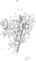
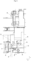
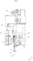
- the tool 1 12 shows an exemplary embodiment of a tool 1.
- the tool 1 is preferably a crimping tool for separating and crimping contacts on a line.
- the tool 1 is set up to provide a contact carrier strip 13, to which contacts 11 are attached, in a process direction X with the aid of a feed 62 in a processing area. At least one contact 11 can be separated from the contact carrier strip 13 in the processing area.
- a contact 11 is separated from the contact carrier strip 13 with the aid of a cutter 30.
- a contact 11 which was preferably placed on an anvil 38 in the processing area, is separated from the contact carrier strip 13 by a shearing movement between the anvil 38 and the cutter 30 separated.
- an actuator 20 exerts a force on the cutter 30 in the exemplary embodiment. To do this, the actuator 20 is moved from its home position or open position (see Fig. 1 ) spaced from cutter 30 toward cutter 30 or to a closed position (see Fig. 3 ). With a continuous movement of the actuator 20, it presses on contact surfaces 34 on the cutter 30 and moves it relative to the anvil 38.
- the movement of the actuator 20 and cutter 30 is preferably transverse, in particular perpendicular, to the longitudinal direction X of the contact carrier strip 13.
- a first height H1 of the Cutter 30 relative to anvil 38 or a lower screen guide 36 decreases to a second height H2.
- the contact carrier strip guide 32 or the bearing surfaces 34 can serve as reference points on the cutter 30 for determining the height.
- the force of the actuator 20 on the cutter 30 preferably takes place during a split cycle of the crimping tool 1, so that only the force required for cutting acts on the cutter 30.
- an upper shield guide 22 mounted on the actuator 20 preferably abuts a lower shield guide 36 mounted on the tool 1.
- a line guide is preferably formed, in which a line 10 can be arranged even when the actuator 20 and the cutter 30 are in abutment with one another.
- the line 10 is preferably a multi-layer line, which in particular has an inner conductor.
- an inner conductor contact 12 is already attached to the inner conductor.
- At least one braided shield 14 surrounds the inner conductor.
- the braided shield is bent away from the line 10, ie set up. A distance can be formed between the erected screen and the inner conductor contact along the longitudinal direction Y of the line 10 .
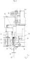
- the braided shield or shield 14 is bent away from the line 10 by 90 degrees. The bending increases the outer diameter of the cable 10 in the area of the bent braided shield 14 (see Fig. 2 ).
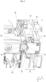
- the inner conductor contact 12 can extend through the line guide mentioned in the cutter 30, but the line 10 as a whole can only be inserted into the cutter 30 until the erected braided shield 14 comes into contact with the actuator 20 and/or the cutter 30 (see Fig. figs 3 and 4 ). In this position, the line 10 or the inner conductor contact 12 is only partially, and not completely, arranged in the outer conductor contact 11 .
- the outer conductor contact 11 is an exemplary embodiment of a first contact that is to be added to the line 10 .
- the outer conductor contact 11 is fixed on the anvil 38 by a hold-down device 24 .
- the crimping tool is opened to the maximum, so that a distance between the anvil and the hold-down device can have a maximum stroke of about 40 mm.
- the hold-down device 24 preferably moves simultaneously and parallel to the actuator 20. For fixing, the hold-down device 24 touches the outer conductor contact 11 in the position when the actuator 20 comes into abutment with the cutter 30.
- the hold-down device 24 is preferably spring-mounted.
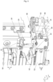
- the hold-down device 24 exerts a compressive force on the first contact or outer conductor contact 11 and thus fixes the contact 11 on the anvil 38 (see Fig. 4 ).
- the fixation acts transversely, in particular perpendicularly, to the outer conductor contact 11 or the longitudinal direction Y of the line 10.
- the fixation takes place by frictional locking. Due to the springing, a reduced force acts on the outer conductor contact 11 so that it is not damaged.
- a stop 42 is moved from an inactive position P1 to an active position P2.
- the movement is effected by a first cylinder 40 which can be extended and retracted along one direction.
- the direction is preferably along the longitudinal direction Y of the line 10 or the outer conductor contact 11.
- the stop 42 has an opening 44 which is designed such that the first contact or the outer conductor contact 11 can be accommodated therein.
- the stop 42 is pushed with the opening 44 over the outer conductor contact 11 (cf. figure 2 and 4 ).
- the outer conductor contact 11 is fixed with the aid of the stop 42 in a form-fitting manner.
- the first cylinder 40 can be operated pneumatically.
- FIG 5 shows the tool 1 in a subsequent state.
- the actuator 20 and the hold-down device 24 are again in their basic position or open position, ie spaced apart from the cutter 30 and anvil 38.
- the first Contact 11, or outer conductor contact is still fixed by stop 42. Due to the partial insertion into the outer conductor contact 11, the line 10 is already in the correct alignment with the outer conductor contact 11.
- the line 10 can be held in position by a holding device such as a gripper (not shown).
- the cutter 30 is lowered to a third height H3 so that the portion of the erected braided shield 14 that is in contact with the cutter 30 is no longer blocked by the cutter 30 in the longitudinal direction Y of the line 10 .
- a second cylinder 50 which is coupled to the contact guide track 52, is extended by a gap height S (see Fig. figure 5 ).
- the contact guide track 52 drops from a first distance difference D1 to a second distance difference D2, with the difference being able to be equal to the gap height S, in relation to the lower screen guide 36, which is firmly connected to the tool 1.
- the contact guide track 52 is coupled to the cutter 30 by a driver.
- the driver can for example as Be realized bolt or screw connection.
- the lowering of the contact guide track 52 results in the cutter 30 also being lowered to the third height H3 in relation to the lower screen guide 36 .
- the retraction of the actuator 20 and the hold-down device 24 as well as the simultaneous lowering of the cutter 30 means that the line 10 with the shielding braid 14 set up is no longer impeded along the longitudinal axis Y of the line 10 .
- the line 10, and in particular the inner conductor contact 12 can be fully inserted into the first contact or the outer conductor contact 11 (see Fig. 6 ).
- FIG. 6 shows an end position of the tool 1, in which the line 10 with the outer conductor contact 11 joined has been removed from the tool 1. Joining only includes arranging the line 10 or the inner conductor contact 12, which is attached to the line 10, in the outer conductor contact 11. The outer conductor contact 11 can be attached to the line 10 in a separate subsequent process step.
- the cutter 30 is back at its first height H1.
- the second cylinder 50 was retracted, as a result of which the contact guide track 52, and preferably also the cutter 30 via the driver, moved from the lowered position back into the basic position.
- a third cylinder 60 can be moved in and out again along a process direction X (see Fig. 1 ).
- the third cylinder 60 is coupled to a feed 62, so that the movements of the third cylinder 60 move the feed 62 accordingly, which in turn moves the contact carrier strip 13 forward by a specific length in the process direction X, so that a further contact 11 or The outer conductor contact is placed on the anvil 38.
- a new process cycle can then begin.
Landscapes
- Engineering & Computer Science (AREA)
- Manufacturing & Machinery (AREA)
- Manufacturing Of Electrical Connectors (AREA)
- Excavating Of Shafts Or Tunnels (AREA)
Abstract
Description
- Die Erfindung betrifft ein Verfahren und ein Werkzeug zum Abtrennen und Fügen eines Kontakts mit einer Leitung, die einen aufgestellten Schirm aufweist.
- Die Druckschrift
DE 20 2017 003 670 U1 betrifft eine Vorrichtung zum Crimpen zumindest einer Ader eines Kabels. Die Druckschrift beschreibt dabei ein Kabel, das einen Schirm aufweist, dessen Ende aufgestellt ist. In der Druckschrift kann eine Vorrichtung zum Crimpen der zumindest einen Ader einen so genannten Abschneider zum Abtrennen einzelner Crimpkontakte von einem Trägerstreifen aufweisen. Im Zuge der Konfektionierung des Kabels, wird das Kabel zum Ende hin abgemantelt und dessen Ader an einem Ende abisoliert. Zudem wird der Schirm aufgestellt, so dass dieser radial nach außen absteht. Im Betrieb der Vorrichtung wird das so vorbereitete Kabel, entgegen einer y-Richtung zunächst in eine Ausnehmung eines Auflagers, dann in eine Öffnung des Abschneiders eingeführt und schließlich auf eine Auflagefläche gelegt. Zum eigentlichen Crimpen wird der Crimper in einer z-Richtung über einen vordefinierten Hub hinweg relativ zu einem Amboss von einer Ruheposition in eine Bearbeitungsposition bzw. in eine Crimpposition bewegt. - Bei diesem Prozess werden Crimplaschen plastisch so verformt, dass sich diese fest um die Ader schließen. Die Druckschrift beschreibt weiterhin, dass der Abschneider eine Öffnung aufweist, in die das Kabel, das den Schirm aufweist, dessen Ende aufgestellt ist, so einführbar ist, dass der aufgestellte Schirm in der Öffnung des Abschneiders platzierbar ist.
- Im obigen Stand der Technik ergibt sich zumindest der Nachteil, dass das Kabel mit dem aufgestellten Schirm nach der Positionierung des Schirms in der Öffnung des Abschneiders nicht mehr beliebig entlang der Längsrichtung des Kabels, insbesondere nicht in Richtung des Kontakts, bewegt werden kann. Dadurch ist eine nachfolgende Verschiebung des Kabels entlang seiner Längsrichtung, um zum Beispiel einen zusätzlichen Fügeschritt durchzuführen, nicht möglich.
- Es ist daher eine Aufgabe der vorliegenden Erfindung eine Vorrichtung und ein Verfahren bereitzustellen mit denen eine Leitung mit aufgestelltem Schirm flexibel verarbeitbar ist.
- Die oben genannte Aufgabe wird durch ein Abtrenn- und Fügeverfahren nach Anspruch 1 sowie ein Werkzeug zum Abtrennen und Fügen eines Kontakts mit einer Leitung nach Anspruch 9 gelöst. Weitere vorteilhafte Ausgestaltungsformen der Erfindung lassen sich den Unteransprüchen, der Beschreibung sowie den Zeichnungen entnehmen.
- Insbesondere wird die oben genannte Aufgabe gelöst durch ein Abtrenn- und Fügeverfahren für einen ersten Kontakt mit einer Leitung, die einen aufgestellten Schirm aufweist, wobei das Verfahren die folgenden Schritte aufweist: Bewegen eines Betätigers und eines Niederhalters von einer offenen Position in eine geschlossene Position, so dass der Betätiger auf einen Abschneider einwirkt und der erste Kontakt, der an einem Kontaktträgerstreifen bereitgestellt werden kann, von dem Kontaktträgerstreifen getrennt werden kann, und der erste Kontakt durch den Niederhalter fixiert werden kann, Fügen der Leitung in den ersten Kontakt, bis der aufgestellte Schirm der Leitung an dem Betätiger und/oder Abschneider anliegt, Aktivieren eines ersten Zylinders, so dass ein Anschlag von einer inaktiven Position in eine aktive Position bewegt wird, wobei der erste Kontakt durch den Anschlag in der aktiven Position fixiert werden kann, Bewegen des Betätigers und des Niederhalters von der geschlossenen Position in die offene Position, und simultanes Aktivieren eines zweiten Zylinders, so dass eine Kontaktführungsbahn sowie der Abschneider von einer Grundposition in eine abgesenkte Position bewegt werden, und Fügen der Leitung in eine Endposition im ersten Kontakt.
- Das Verfahren ermöglicht ein durchgängiges Abtrennen eines ersten Kontakts von einem Kontaktträgerstreifen und Fügen einer Leitung in den abgetrennten Kontakt in einem Prozesszyklus. Insbesondere ermöglicht das Verfahren ein Abtrennen und Fügen eines Außenleiterkontakts mit einer Leitung, die einen befestigten Innenleiterkontakt und einen aufgestellten Schirm aufweist. Das Fügen einer Leitung mit aufgestelltem Schirm in einen Außenleiterkontakt benötigt ein weites Einführen der Leitung bzw. des Innenleiterkontakts in den Außenleiterkontakt. Die Leitung muss entlang ihrer Längsrichtung tief in den Außenleiterkontakt eingeführt werden, um die Leitung mit dem Innenleiterkontakt korrekt in dem Außenleiterkontakt zu positionieren. Wenn das Fügen direkt am Abschneider eines Crimpwerkzeugs erfolgen soll, so muss die Leitung entlang ihrer Längsachse bewegbar sein. Mit dem hier beschriebenen Verfahren kann die Leitung mit aufgestelltem Schirm direkt am Abschneider vollständig bis zu einer Endposition im ersten Kontakt bzw. Außenleiterkontakt gefügt werden, da die Leitung mit aufgestelltem Schirm ungehindert verschoben werden kann. Das Verfahren vereinfacht die Kabelkonfektion.
- Bevorzugt umfasst der Schritt des Bewegens des Betätigers und des Niederhalters zwischen der offenen und der geschlossenen Position, eine Bewegung entlang einer ersten Richtung, insbesondere quer zur Längsrichtung der Leitung. Die Bewegung hat den Vorteil, dass eine gerichtete Kraftwirkung von dem Betätiger auf den Abschneider möglich ist. Insbesondere ist bei einer senkrechten Bewegung eine saubere Trennung zwischen Kontakt und Kontaktträgerstreifen möglich, ohne unerwünschte Verformungen. Weiterhin wirkt die Fixierung des Niederhalters kraftschlüssig auf den ersten Kontakt und ermöglicht eine zuverlässige Fixierung.
- Bevorzugt umfasst der Schritt des Bewegens des Anschlags zwischen der aktiven Position und der inaktiven Position, eine Bewegung entlang einer zweiten Richtung, insbesondere entlang der Längsrichtung der Leitung. Die Bewegung ermöglicht eine Fixierung des ersten Kontakts unabhängig von der Anordnung oder Bewegung des Niederhalters. Insbesondere findet die Bewegung auf der leitungsabgewandten Seite des ersten Kontakts statt. So engt die Bewegung nicht den Bewegungsbereich der Leitung ein. Schließlich kann durch die Bewegung eine formschlüssige Fixierung des ersten Kontakts über den Anschlag bzw. die Öffnung im Anschlag erreicht werden.
- Bevorzugt umfasst das Aktivieren des ersten und/oder zweiten Zylinders ein Ausfahren des ersten und/oder zweiten Zylinders.
- Bevorzugt wird das Bewegen des Betätigers und des Niederhalters in einem Split-Cycle eines Crimpwerkzeugs durchgeführt. Für das Verfahren kann ein Crimpwerkzeug verwendet werden, das prinzipiell im Stand der Technik bekannt ist. Das Vereinfacht die Anwendung des Verfahrens. Für das Abtrennen und Fügen des ersten Kontakts wird jedoch nicht die volle Kraft des Crimpwerkzeugs, wie sie zum Crimpen notwendig ist, gebraucht, so dass es materialschonender ist, die Bewegungen nur in einem Split-Cycle durchzuführen, indem nur ein Bruchteil der maximalen Kraft des Crimpwerkzeugs auf den ersten Kontakt wirkt.
- Bevorzugt weist das Verfahren weiterhin den Schritt auf: Einfahren des ersten Zylinders, so dass der Anschlag von der aktiven Position in die inaktive Position bewegt wird, wobei der erste Kontakt freigegeben wird. Das Einfahren hat den Effekt, dass der erste Kontakt, in den die Leitung gefügt wurde, wieder frei beweglich ist und aus dem Werkzeug entnommen werden kann. Zusätzlich wurde der Anschlag wieder in seine Grundstellung für einen neuen Prozesszyklus gebracht.
- Bevorzugt weist das Verfahren weiterhin den Schritt auf: Einfahren des zweiten Zylinders, so dass die Kontaktführungsbahn sowie der Abschneider von der abgesenkten Position in die Grundposition Position bewegt werden. Das Zurückführen oder Anheben der Kontaktführungsbahn hat den Effekt, dass ein neuer erster Kontakt beim Durchführen durch die Kontaktführungsbahn wieder auf dem Amboss positioniert werden kann. Zusätzlich befinden sich die Kontaktführungsbahn sowie der Abschneider wieder in ihrer Grundstellung für einen neuen Prozesszyklus.
- Bevorzugt weist das Verfahren weiterhin den Schritt auf: Ein- und Ausfahren eines dritten Zylinders der mit einem Vorschub gekoppelt ist, so dass der Kontaktträgerstreifen mit Hilfe des Vorschubs um eine vorbestimmte Distanz in Prozessrichtung bewegt werden kann und ein nachfolgender erster Kontakt am Abschneider bereitgestellt werden kann. Dieser Schritt ermöglicht den Beginn eines neuen Prozesszyklus. Die Verwendung eines dritten Zylinders, der insbesondere baugleich mit dem ersten und/oder zweiten Zylinder ist, ermöglicht das zeitlich abgestimmte Ansprechen und Aktivieren aller drei Zylinder, da deren Verhalten gleich ist, so dass ein synchroner Prozesszyklus erreicht werden kann.
- Die oben genannte Aufgabe wird weiterhin insbesondere gelöst durch ein Werkzeug zum Abtrennen und Fügen eines ersten Kontakts, der an einem Kontaktträgerstreifen bereitgestellt wird, mit einer Leitung, die einen aufgestellten Schirm aufweist, aufweisend eine Kontaktführungsbahn zum Bereitstellen des Kontaktträgerstreifens mit ersten Kontakten, einen Abschneider zum Abtrennen eines ersten Kontakts von dem Kontaktträgerstreifen, einen Niederhalter zum Fixieren des ersten Kontakts, einen ersten Zylinder mit einem Anschlag, wobei der Zylinder den Anschlag von einer inaktiven Position in eine aktive Position bewegen kann und der Anschlag den ersten Kontakt in der aktiven Position fixieren kann, und einen zweiten Zylinder, der mit der Kontaktführungsbahn und dem Abschneider gekoppelt ist, wobei der zweite Zylinder die Kontaktführungsbahn und den Abschneider von einer Grundposition in eine abgesenkte Position bewegen kann.
- Das Werkzeug ermöglicht die Verarbeitung von Leitungen, die einen aufgestellten Schirm aufweisen. Durch die Zylinder, insbesondere den ersten und zweiten Zylinder, können Bauteile am Werkzeug verschoben werden, so dass die Bauteile einer Bewegung der Leitung nicht im Wege stehen. Die gewonnene Bewegungsfreiheit der Leitung ermöglicht es Prozessschritte, insbesondere innerhalb eines Prozesszyklus, an dem Werkzeug durchzuführen, die bei Werkzeug im Stand der Technik nicht möglich sind.
- Bevorzugt umfasst der erste Kontakt einen Außenleiterkontakt, und an der Leitung ist bevorzugt ein zweiter Kontakt, insbesondere ein Innenleiterkontakt, befestigt. Das Verarbeiten von Außenleiterkontakten, und insbesondere das Fügen von Leitungen mit einem Innenleiterkontakt und einem aufgestellten Schirm in einen Außenleiterkontakt, erfordern ein tiefes Einsetzen oder Positionieren der Leitung in dem Außenleiterkontakt. Für das tiefe Positionieren muss die Leitung zumindest volle Bewegungsfreiheit entlang ihrer Längsachse aufweisen. Mit dem vorliegenden Werkzeug ist diese Bewegungsfreiheit möglich bzw. gegeben.
- Bevorzugt ist die Kontaktführungsbahn über einen Mitnehmer mit dem Abschneider gekoppelt. Die Kopplung des Abschneiders über einen Mitnehmer an der Kontaktführungsbahn ermöglicht ein passgenaues Einstellen des Bewegungsverhaltens des Abschneiders in Bezug auf die Kontaktführungsbahn. So kann eine Mitnahmehöhe zum Beispiel in Bezug auf die Höhe des Abschneiders in seiner Grundposition angepasst werden.
- Bevorzugt fixiert der Niederhalter den ersten Kontakt über eine Federspannung. Die Federspannung ermöglicht es die Druckkraft des Niederhalters anzupassen. Sollten plötzlich unerwartet hohe Kräfte in Richtung des ersten Kontakts auftreten, kann der Niederhalter diese über die Federspannung ausgleichen. Bei Bewegungen des Werkzeugs gewährleistet die Federspannung einen zuverlässigen Kontakt zwischen Niederhalter und erstem Kontakt.
- Bevorzugt umfasst das Werkzeug ein Crimpwerkzeug. Ein Crimpwerkzeug ist für die Kabelkonfektion geeignet. Insbesondere ist ein Crimpwerkzeug eingerichtet einen Kontakt von einem Kontaktträgerstreifen zu trennen und Kräfte auf den abgetrennten Kontakt auszuüben. Die Kräfte können dabei lediglich Haltekräfte sein, die beim Fügen benötigt werden. Die Verwendung bzw. das Umrüsten eines an sich bekannten Werkzeugs erleichtert das Verwenden bzw. Umrüsten.
- Bevorzugt weist das Werkzeug weiterhin einen dritten Zylinder auf, der mit einem Vorschub gekoppelt ist, wobei der dritte Zylinder den Vorschub in einer Prozessrichtung bewegen kann, so dass der Kontaktträgerstreifen mit Hilfe des Vorschubs in der Prozessrichtung bewegbar ist. Der dritte Zylinder ist bevorzugt baugleich mit dem ersten und/oder zweiten Zylinder, wodurch das Verhalten der Zylinder gleich ist. Die baugleichen Zylinder erleichtern oder ermöglichen das synchrone Ausführen eines Prozesses.
- Die folgende Beschreibung von Ausführungsbeispielen erfolgt unter Bezugnahme auf die begleitenden Figuren. Dabei zeigen:
- Fig. 1
- eine perspektivische Ansicht einer Ausführungsform eines Werkzeugs;
- Fig. 2
- eine Seitenansicht eines Ausschnitts des Werkzeugs aus
Fig. 1 in einer Ausgangsposition; - Fig. 3
- eine perspektivische Ansicht eines Ausschnitts des Werkzeugs, bei der eine Leitung mit aufgestelltem Schirm teilweise in einen ersten Kontakt gefügt wurde;
- Fig. 4
- eine Seitenansicht der Darstellung aus
Fig. 3 ; - Fig. 5
- eine perspektivische Ansicht eines Ausschnitts des Werkzeugs, bei der eine Leitung mit aufgestelltem Schirm vollständig in einen ersten Kontakt gefügt wurde;
- Fig. 6
- eine Seitenansicht der Darstellung aus
Fig. 5 ; und - Fig. 7
- eine Seitenansicht eines Ausschnitts des Werkzeugs aus
Fig. 1 in einer Endposition. - Im Folgenden werden Ausführungsbeispiele im Detail mit Bezug auf die Figuren beschrieben.
-
Fig. 1 zeigt ein Ausführungsbeispiel eines Werkzeugs 1. Das Werkzeug 1 ist bevorzugt ein Crimpwerkzeug zum Abtrennen und Crimpen von Kontakten an eine Leitung. Das Werkzeug 1 ist eingerichtet einen Kontaktträgerstreifen 13, an dem Kontakte 11 befestigt sind, in einer Prozessrichtung X mit Hilfe eines Vorschubs 62 an einem Verarbeitungsbereich bereitzustellen. In dem Verarbeitungsbereich kann zumindest ein Kontakt 11 von dem Kontaktträgerstreifen 13 abgetrennt werden. - Das Abtrennen eines Kontakts 11 von dem Kontaktträgerstreifen 13 erfolgt in dem dargestellten Ausführungsbeispiel mit Hilfe eines Abschneiders 30. Ein Kontakt 11, der im Verarbeitungsbereich vorzugsweise auf einem Amboss 38 platziert wurde, wird durch eine Scherbewegung zwischen dem Amboss 38 und dem Abschneider 30 vom Kontaktträgerstreifen 13 getrennt. Zum Bewegen des Abschneiders 30 relativ zum Amboss 38, d.h. zum Betätigen des Abschneiders 30, übt im Ausführungsbeispiel ein Betätiger 20 eine Kraft auf den Abschneider 30 auf. Dazu wird der Betätiger 20 aus seiner Grundposition oder offenen Position (s.
Fig. 1 ), die sich beabstandet vom Abschneider 30 befindet, in Richtung des Abschneiders 30 bzw. in eine geschlossene Position bewegt (s.Fig. 3 ). Bei einer fortlaufenden Bewegung des Betätigers 20 drückt dieser auf Auflageflächen 34 am Abschneider 30 und bewegt diesen relativ zum Amboss 38. Die Bewegung von Betätiger 20 und Abschneider 30 erfolgt bevorzugt quer, insbesondere senkrecht, zur Längsrichtung X des Kontaktträgerbands 13. Eine erste Höhe H1 des Abschneiders 30 gegenüber dem Amboss 38 oder einer unteren Schirmführung 36 verringert sich auf eine zweite Höhe H2. Als Referenzpunkte am Abschneider 30 zur Bestimmung der Höhe können die Kontaktträgerstreifenführung 32 oder die Auflageflächen 34 dienen. - Die Kraftwirkung des Betätigers 20 auf den Abschneider 30 findet bevorzugt während eines Split-Cycles des Crimpwerkzeugs 1 statt, so dass nur die zum Abtrennen notwendige Kraft auf den Abschneider 30 wirkt. In der geschlossenen Position, in der sich der Betätiger 20 in Kontakt mit dem Abschneider 30 befindet, liegt bevorzugt eine obere Schirmführung 22, die am Betätiger 20 montiert ist, an einer unteren Schirmführung 36, die am Werkzeug 1 montiert ist, an. An der Kontaktfläche des Abschneiders 30 ist bevorzugt eine Leitungsführung gebildet, in welcher eine Leitung 10, auch wenn sich der Betätiger 20 und der Abschneider 30 in Anschlag miteinander befinden, angeordnet werden kann.
- Die Leitung 10 ist bevorzugt eine mehrschichtige Leitung, die insbesondere einen Innenleiter aufweist. An dem Innenleiter ist in der dargestellten Ausführungsform bereits ein Innenleiterkontakt 12 befestigt. Den Innenleiter umgibt zumindest ein Schirmgeflecht 14. Das Schirmgeflecht ist von der Leitung 10 weggebogen, d.h. aufgestellt. Zwischen dem aufgestellten Schirm und dem Innenleiterkontakt kann entlang der Längsrichtung Y der Leitung 10 ein Abstand gebildet sein. Bevorzugt ist das Schirmgeflecht oder der Schirm 14 um 90 Grad von der Leitung 10 weggebogen. Durch das Aufbiegen erhöht sich der Außendurchmesser der Leitung 10 im Bereich des aufgebogenen Schirmgeflechts 14 (s.
Fig. 2 ). - In dem Zustand, in dem der Betätiger 20 auf Anschlag mit dem Abschneider 30 liegt, kann sich zwar der Innenleiterkontakt 12 durch die erwähnte Leitungsführung im Abschneider 30 erstrecken, die Leitung 10 als Ganzes kann jedoch nur soweit in den Abschneider 30 eingeführt werden, bis das aufgestellte Schirmgeflecht 14 in Anschlag mit dem Betätiger 20 und/oder dem Abschneider 30 gelangt (s.
Figs. 3 und4 ). In dieser Position ist die Leitung 10 bzw. der Innenleiterkontakt 12 lediglich teilweise, und noch nicht vollständig, im Außenleiterkontakt 11 angeordnet. - Der Außenleiterkontakt 11 ist ein Ausführungsbeispiel für einen ersten Kontakt, der auf die Leitung 10 gefügt werden soll. Der Außenleiterkontakt 11 wird in dem dargestellten Ausführungsbeispiel durch einen Niederhalter 24 auf dem Amboss 38 fixiert. In der offenen Position ist das Crimpwerkzeug maximal geöffnet, so dass ein Abstand zwischen dem Amboss und dem Niederhalter einen maximalen Hub von ca. 40 mm aufweisen kann. Der Niederhalter 24 bewegt sich bevorzugt gleichzeitig und parallel zu dem Betätiger 20. Zum Fixieren setzt der Niederhalter 24, in der Position, wenn der Betätiger 20 in Anschlag mit dem Abschneider 30 kommt, auf dem Außenleiterkontakt 11 auf. Der Niederhalter 24 ist bevorzugt federnd gelagert. Bei einer Weiterbewegung des Betätigers 20, zum Betätigen des Abschneiders 30, übt der Niederhalter 24 eine Druckkraft auf den ersten Kontakt bzw. Außenleiterkontakt 11 aus und fixiert den Kontakt 11 damit auf dem Amboss 38 (s.
Fig. 4 ). Die Fixierung wirkt dabei quer, insbesondere senkrecht, zum Außenleiterkontakt 11 bzw. der Längsrichtung Y der Leitung 10. Die Fixierung erfolgt durch Kraftschluss. Durch die Federung wirkt eine reduzierte Kraft auf den Außenleiterkontakt 11, so dass dieser nicht beschädigt wird. Durch die Fixierung kann unter anderem eine gleichbleibende Präzision beim Abtrennen von Kontakten 11 vom Kontaktträgerstreifen 13 erreicht werden. - Um den Außenleiterkontakt 11 in seiner Position zu fixieren, wenn der Niederhalter 24 wieder entfernt wird, wird ein Anschlag 42 von einer inaktiven Position P1 in eine aktive Position P2 bewegt. Die Bewegung erfolgt durch einen ersten Zylinder 40 der entlang einer Richtung ein- und ausgefahren werden kann. Die Richtung liegt bevorzugt entlang der Längsrichtung Y der Leitung 10 bzw. des Außenleiterkontakts 11. In dem dargestellten Ausführungsbeispiel weist der Anschlag 42 eine Öffnung 44 auf, die so ausgebildet ist, dass der erste Kontakt bzw. der Außenleiterkontakt 11 darin aufgenommen werden kann. Der Anschlag 42 wird mit der Öffnung 44 über den Außenleiterkontakt 11 geschoben (vgl.
Fig 2 undFig. 4 ). Die Fixierung des Außenleiterkontakts 11 mit Hilfe des Anschlags 42 erfolgt formschlüssig. Der erste Zylinder 40 kann pneumatisch betrieben werden. -
Fig. 5 zeigt das Werkzeug 1 in einem nachfolgenden Zustand. Um die Leitung 10 bzw. den Innenleiterkontakt 12 vollständig in den ersten Kontakt bzw. Außenleiterkontakt 11 zu fügen, befinden sich der Betätiger 20 und der Niederhalter 24 wieder in Ihrer Grundposition bzw. offenen Position, d.h. beabstandet zum Abschneider 30 und Amboss 38. Der erste Kontakt 11, bzw. Außenleiterkontakt, wird weiterhin durch den Anschlag 42 fixiert. Die Leitung 10 befindet auf Grund der teilweisen Fügung in den Außenleiterkontakt 11 bereits in der korrekten Ausrichtung zum Außenleiterkontakt 11. Die Leitung 10 kann durch eine Haltevorrichtung wie einen Greifer (nicht gezeigt) auf Position gehalten werden. - Damit der Teilbereich des aufgestellten Schirmgeflechts 14, der in Anschlag mit dem Abschneider 30 liegt, nicht mehr vom Abschneider 30 in Längsrichtung Y der Leitung 10 blockiert wird, wird der Abschneider 30 auf eine dritte Höhe H3 abgesenkt. Zum Absenken wird ein zweiter Zylinder 50, der mit der Kontaktführungsbahn 52 gekoppelt ist, um ein Spalthöhe S ausgefahren (s.
Fig. 5 ). Dadurch senkt sich die Kontaktführungsbahn 52 von einem ersten Distanzunterschied D1 auf einen zweiten Distanzunterschied D2, wobei die Differenz gleich der Spalthöhe S sein kann, gegenüber der unteren Schirmführung 36, die fest mit dem Werkzeug 1 verbunden ist. In einem Ausführungsbeispiel ist die Kontaktführungsbahn 52 durch einen Mitnehmer mit dem Abschneider 30 gekoppelt. Der Mitnehmer kann zum Beispiel als Bolzen oder Schraubverbindung realisiert sein. Das Absenken der Kontaktführungsbahn 52 führt dazu, dass auch der Abschneider 30 auf die dritte Höhe H3 gegenüber der unteren Schirmführung 36 abgesenkt wird. - Wie
Fig. 5 zeigt, führt das Einfahren des Betätigers 20 und des Niederhalters 24 sowie das simultane Absenken des Abschneiders 30 dazu, dass die Leitung 10 mit aufgestelltem Schirmgeflecht 14 nicht mehr entlang der Längsachse Y der Leitung 10 behindert wird. In dieser Position des Werkzeugs 1 kann die Leitung 10, und insbesondere der Innenleiterkontakt 12, vollständig in den ersten Kontakt bzw. den Außenleiterkontakt 11 gefügt werden (s.Fig. 6 ). -
Fig. 6 zeigt eine Endposition des Werkzeugs 1, bei dem die Leitung 10 mit gefügtem Außenleiterkontakt 11 aus dem Werkzeug 1 entnommen wurde. Das Fügen umfasst lediglich das Anordnen der Leitung 10, bzw. des Innenleiterkontakts 12, der an der Leitung 10 befestigt ist, in dem Außenleiterkontakt 11. Eine Befestigung des Außenleiterkontakts 11 an der Leitung 10 kann in einem separaten nachfolgenden Prozessschritt erfolgen. In der Endposition befindet sich der Abschneider 30 wieder auf seine erste Höhe H1. Dazu wurde der zweite Zylinder 50 eingefahren, wodurch sich die Kontaktführungsbahn 52, und bevorzugt über den Mitnehmer auch der Abschneider 30, von der abgesenkten Position wieder in die Grundposition bewegte. - In einem weiteren Prozessschritt kann ein dritter Zylinder 60 entlang einer Prozessrichtung X ein- und wieder ausgefahren werden (s.
Fig. 1 ). Der dritte Zylinder 60 ist im dargestellten Ausführungsbeispiel mit einem Vorschub 62 gekoppelt, so dass die Bewegungen des dritten Zylinders 60 den Vorschub 62 entsprechend bewegen, wodurch sich wiederum der Kontaktträgerstreifen 13 um eine bestimmte Länge in Prozessrichtung X vorwärtsbewegt, so dass ein weiterer Kontakt 11 bzw. Außenleiterkontakt auf dem Amboss 38 platziert wird. Ein neuer Prozesszyklus kann daraufhin beginnen. -
- 1
- Werkzeug
- 10
- Leitung
- 11
- erster Kontakt
- 12
- zweiter Kontakt
- 13
- Kontaktträgerstreifen
- 14
- aufgestellter Schirm
- 20
- Betätiger
- 22
- obere Schirmführung
- 24
- Niederhalter
- 30
- Abschneider
- 32
- Kontaktträgerstreifenführung
- 34
- Auflagefläche
- 36
- untere Schirmführung
- 38
- Amboss
- 40
- erster Zylinder
- 42
- Anschlag
- 44
- Öffnung
- 50
- zweiter Zylinder
- 52
- Kontaktführungsbahn
- 60
- dritter Zylinder
- 62
- Vorschub
- D1, D2
- erster, zweiter Distanzunterschied
- H1, H2, H3
- erste, zweite, dritte Höhe
- P1, P2
- inaktive, aktive Position
- S
- Spalthöhe
- X
- dritte Richtung (Prozessrichtung)
- Y
- zweite Richtung (Längsrichtung)
- Z
- erste Richtung
Claims (14)
- Abtrenn- und Fügeverfahren für einen ersten Kontakt (11) mit einer Leitung (10), die einen aufgestellten Schirm (14) aufweist, wobei das Verfahren die folgenden Schritte aufweist:a) Bewegen eines Betätigers (20) und eines Niederhalters (24) von einer offenen Position in eine geschlossene Position, so dass der Betätiger (20) auf einen Abschneider (30) einwirkt und der erste Kontakt (11), der an einem Kontaktträgerstreifen (13) bereitgestellt werden kann, von dem Kontaktträgerstreifen (13) getrennt werden kann, und der erste Kontakt (11) durch den Niederhalter (24) fixiert werden kann;b) Fügen der Leitung (10) in den ersten Kontakt (11), bis der aufgestellte Schirm (14) der Leitung (10) an dem Betätiger (20) und/oder Abschneider (30) anliegt;c) Aktivieren eines ersten Zylinders (40), so dass ein Anschlag (42) von einer inaktiven Position (P1) in eine aktive Position (P2) bewegt wird, wobei der erste Kontakt (11) durch den Anschlag (42) in der aktiven Position (P2) fixiert werden kann;d) Bewegen des Betätigers (20) und des Niederhalters (24) von der geschlossenen Position in die offene Position, und simultanes Aktivieren eines zweiten Zylinders (50), so dass eine Kontaktführungsbahn (52) sowie der Abschneider (30) von einer Grundposition in eine abgesenkte Position bewegt werden; unde) Fügen der Leitung (10) in eine Endposition im ersten Kontakt (11).
- Abtrenn- und Fügeverfahren nach Anspruch 1, bei dem der Schritt des Bewegens des Betätigers (20) und des Niederhalters (24) zwischen der offenen und der geschlossenen Position, eine Bewegung entlang einer ersten Richtung (Z), insbesondere quer zur Längsrichtung (Y) der Leitung (10), umfasst.
- Abtrenn- und Fügeverfahren nach Anspruch 1 oder 2, bei dem der Schritt des Bewegens des Anschlags (42) zwischen der aktiven Position (P2) und der inaktiven Position (P1), eine Bewegung entlang einer zweiten Richtung (Y), insbesondere entlang der Längsrichtung (Y) der Leitung (10), umfasst.
- Abtrenn- und Fügeverfahren nach einem der Ansprüche 1 - 3, bei dem das Aktivieren des ersten und/oder zweiten Zylinders (40, 50) ein Ausfahren des ersten und/oder zweiten Zylinders (40, 50) umfasst.
- Abtrenn- und Fügeverfahren nach einem der Ansprüche 1 - 4, bei dem das Bewegen des Betätigers (20) und des Niederhalters (24) in einem Split-Cycle eines Crimpwerkzeugs (1) durchgeführt wird.
- Abtrenn- und Fügeverfahren nach Anspruch 4, weiterhin aufweisend den Schritt: Einfahren des ersten Zylinders (40), so dass der Anschlag (42) von der aktiven Position (P2) in die inaktive Position (P1) bewegt wird, wobei der erste Kontakt (11) freigegeben wird.
- Abtrenn- und Fügeverfahren nach Anspruch 4 oder 6, weiterhin aufweisend den Schritt: Einfahren des zweiten Zylinders (50), so dass die Kontaktführungsbahn (52) sowie der Abschneider (30) von der abgesenkten Position in die Grundposition Position bewegt werden.
- Abtrenn- und Fügeverfahren nach einem der Ansprüche 1 - 7, weiterhin aufweisend den Schritt: Ein- und Ausfahren eines dritten Zylinders (60) der mit einem Vorschub (62) gekoppelt ist, so dass der Kontaktträgerstreifen (13) mit Hilfe des Vorschubs (62) um eine vorbestimmte Distanz in Prozessrichtung (X) bewegt werden kann und ein nachfolgender erster Kontakt (11) am Abschneider (30) bereitgestellt werden kann.
- Werkzeug (1) zum Abtrennen und Fügen eines ersten Kontakts (11), der an einem Kontaktträgerstreifen (13) bereitgestellt wird, mit einer Leitung (10), die einen aufgestellten Schirm (14) aufweist, aufweisend:a) eine Kontaktführungsbahn (52) zum Bereitstellen des Kontaktträgerstreifens (13) mit ersten Kontakten (11);b) einen Abschneider (30) zum Abtrennen eines ersten Kontakts (11) von dem Kontaktträgerstreifen (13);c) einen Niederhalter (24) zum Fixieren des ersten Kontakts (11);d) einen ersten Zylinder (40) mit einem Anschlag (42), wobei der Zylinder (40) den Anschlag (42) von einer inaktiven Position (P1) in eine aktive Position (P2) bewegen kann und der Anschlag (42) den ersten Kontakt (11) in der aktiven Position (P2) fixieren kann; unde) einen zweiten Zylinder (50), der mit der Kontaktführungsbahn (52) und dem Abschneider (30) gekoppelt ist, wobei der zweite Zylinder (50) die Kontaktführungsbahn (52) und den Abschneider (30) von einer Grundposition in eine abgesenkte Position bewegen kann.
- Werkzeug (1) nach Anspruch 9, bei dem der erste Kontakt (11) einen Außenleiterkontakt umfasst, und an der Leitung (10) bevorzugt ein zweiter Kontakt (12), insbesondere ein Innenleiterkontakt, befestigt ist.
- Werkzeug (1) nach Anspruch 9 oder 10, bei dem die Kontaktführungsbahn (52) über einen Mitnehmer mit dem Abschneider (30) gekoppelt ist.
- Werkzeug (1) nach einem der Anspruch 9 - 11, bei dem der Niederhalter (24) den ersten Kontakt (11) über eine Federspannung fixiert.
- Werkzeug (1) nach einem der Ansprüche 9 - 12, bei dem das Werkzeug (1) ein Crimpwerkzeug umfasst.
- Werkzeug (1) nach einem der Ansprüche 9 - 13, weiterhin aufweisend einen dritten Zylinder (60), der mit einem Vorschub (62) gekoppelt ist, wobei der dritte Zylinder (60) den Vorschub (62) in einer Prozessrichtung (X) bewegen kann, so dass der Kontaktträgerstreifen (13) mit Hilfe des Vorschubs (62) in der Prozessrichtung (X) bewegbar ist.
Applications Claiming Priority (1)
| Application Number | Priority Date | Filing Date | Title |
|---|---|---|---|
| DE102021121495.5A DE102021121495A1 (de) | 2021-08-19 | 2021-08-19 | Verfahren und Werkzeug zum Abtrennen und Fügen eines Kontakts mit einer Leitung |
Publications (2)
| Publication Number | Publication Date |
|---|---|
| EP4138234A1 true EP4138234A1 (de) | 2023-02-22 |
| EP4138234B1 EP4138234B1 (de) | 2025-02-26 |
Family
ID=82701687
Family Applications (1)
| Application Number | Title | Priority Date | Filing Date |
|---|---|---|---|
| EP22186413.5A Active EP4138234B1 (de) | 2021-08-19 | 2022-07-22 | Verfahren und werkzeug zum abtrennen und fügen eines kontakts mit einer leitung |
Country Status (4)
| Country | Link |
|---|---|
| EP (1) | EP4138234B1 (de) |
| CN (1) | CN115708280B (de) |
| DE (1) | DE102021121495A1 (de) |
| MX (1) | MX2022009768A (de) |
Cited By (1)
| Publication number | Priority date | Publication date | Assignee | Title |
|---|---|---|---|---|
| EP4422005A1 (de) * | 2023-02-23 | 2024-08-28 | MD Elektronik GmbH | Crimpwerkzeug und crimpverfahren |
Citations (3)
| Publication number | Priority date | Publication date | Assignee | Title |
|---|---|---|---|---|
| JP2007311062A (ja) * | 2006-05-16 | 2007-11-29 | Auto Network Gijutsu Kenkyusho:Kk | 端子圧着装置 |
| JP4589946B2 (ja) * | 2007-07-12 | 2010-12-01 | 日本航空電子工業株式会社 | 端子圧着機 |
| DE202017003670U1 (de) | 2017-07-13 | 2017-08-04 | Md Elektronik Gmbh | Vorrichtung zum Crimpen einer Ader eines Kabels |
Family Cites Families (9)
| Publication number | Priority date | Publication date | Assignee | Title |
|---|---|---|---|---|
| CH693370A5 (de) * | 1997-06-30 | 2003-06-30 | Komax Holding Ag | Verfahren und Vorichtung zur Ueberführung von Kontakten zu einer Kontaktverarbeitungsstation. |
| GB0002203D0 (en) * | 2000-01-31 | 2000-03-22 | Strix Ltd | Controls for electric liquid heating vessels |
| JP5172072B2 (ja) * | 2003-10-28 | 2013-03-27 | コマツクス・ホールデイング・アー・ゲー | ワイヤ処理装置 |
| CN101228675A (zh) * | 2005-06-23 | 2008-07-23 | 施洛伊尼格控股有限公司 | 用于不同的压接和压制加工特别是用于线缆组件的压接机 |
| WO2008087938A1 (ja) * | 2007-01-16 | 2008-07-24 | Japan Automatic Machine Co., Ltd. | 端子圧着方法、端子圧着装置及び端子圧着電線製造装置 |
| FR2923074B1 (fr) * | 2007-10-29 | 2009-12-11 | Areva T & D Ag | Actionneur electromecanique et sectionneur haute ou moyenne tension muni d'un tel actionneur |
| JP5195230B2 (ja) * | 2008-09-26 | 2013-05-08 | 住友電装株式会社 | 端子金具付き電線 |
| EP2905849B1 (de) * | 2014-02-07 | 2023-07-05 | Yazaki Europe Ltd. | Crimpwerkzeug |
| DE102018132530B4 (de) * | 2018-12-17 | 2021-09-23 | Md Elektronik Gmbh | Laserschneidevorrichtung zum Laserschneiden von Schirmdrähten für geschirmte Leitungen und Verfahren zum Laserschneiden von Schirmdrähten mit einer solchen Laserschneidevorrichtung |
-
2021
- 2021-08-19 DE DE102021121495.5A patent/DE102021121495A1/de active Pending
-
2022
- 2022-07-22 EP EP22186413.5A patent/EP4138234B1/de active Active
- 2022-08-09 MX MX2022009768A patent/MX2022009768A/es unknown
- 2022-08-12 CN CN202210968267.4A patent/CN115708280B/zh active Active
Patent Citations (3)
| Publication number | Priority date | Publication date | Assignee | Title |
|---|---|---|---|---|
| JP2007311062A (ja) * | 2006-05-16 | 2007-11-29 | Auto Network Gijutsu Kenkyusho:Kk | 端子圧着装置 |
| JP4589946B2 (ja) * | 2007-07-12 | 2010-12-01 | 日本航空電子工業株式会社 | 端子圧着機 |
| DE202017003670U1 (de) | 2017-07-13 | 2017-08-04 | Md Elektronik Gmbh | Vorrichtung zum Crimpen einer Ader eines Kabels |
Cited By (1)
| Publication number | Priority date | Publication date | Assignee | Title |
|---|---|---|---|---|
| EP4422005A1 (de) * | 2023-02-23 | 2024-08-28 | MD Elektronik GmbH | Crimpwerkzeug und crimpverfahren |
Also Published As
| Publication number | Publication date |
|---|---|
| DE102021121495A1 (de) | 2023-02-23 |
| CN115708280A (zh) | 2023-02-21 |
| MX2022009768A (es) | 2023-02-20 |
| EP4138234B1 (de) | 2025-02-26 |
| CN115708280B (zh) | 2026-03-10 |
Similar Documents
| Publication | Publication Date | Title |
|---|---|---|
| EP4059124B1 (de) | Vorrichtung zum umformen eines in einem statorkern angeordneten leiterstücks sowie ein entsprechendes verfahren | |
| EP2026433B1 (de) | Zange zum Abisolieren eines Kabels | |
| EP3270478A1 (de) | Vorrichtung zur bearbeitung von kabelenden | |
| EP2551962A1 (de) | Elektrische Anschlussvorrichtung | |
| DE112016005790T5 (de) | Gecrimpte Klemme | |
| EP2190080B1 (de) | Vorrichtung zum Crimpen oder Abisolieren einer Ader eines mehradrigen Kabels | |
| EP4138234B1 (de) | Verfahren und werkzeug zum abtrennen und fügen eines kontakts mit einer leitung | |
| EP3824521B1 (de) | Vorrichtung und verfahren zum bearbeiten eines endes eines elektrischen kabels | |
| DE112022002963T5 (de) | Kabelabisoliervorrichtung | |
| DE4446402C2 (de) | Verfahren zum spanlosen Formen von Bundringen in einer Hülse, die zum Halten eines Schlauches dient | |
| EP4164073B1 (de) | Abschneider | |
| EP3520179B1 (de) | Vorrichtung, verfahren und system zum inverscrimpen | |
| DE102021108215B3 (de) | Verfahren und Vorrichtung zum Bearbeiten eines Kabels | |
| DE102015121743A1 (de) | Schneidklemmwerkzeug und Schneidklemme | |
| DE4444857C1 (de) | Verfahren und Vorrichtung zur Herstellung mindestens einer Öffnung in der Wandung eines rohrartigen Teils | |
| DE202017003670U1 (de) | Vorrichtung zum Crimpen einer Ader eines Kabels | |
| DE3926782C1 (en) | Cutting cable to length and stripping - sliding clamp in closed position along predetermined path after cutting cable sleeve or cutting through cable | |
| DE102022128466A1 (de) | Vorrichtung und Verfahren zum Ausbilden von Leitungssätzen | |
| EP4422005B1 (de) | Crimpwerkzeug und crimpverfahren | |
| DE2825106C2 (de) | Vorrichtung zum Zusammenbauen eines Kreuzgelenkes | |
| DE102019117856A1 (de) | Magazin zur Verarbeitung von Aderendhülsen und Handwerkzeug zum Verpressen von Aderendhülsen | |
| EP3840125B1 (de) | Verfahren und vorrichtung zum herstellen einer leitungsanordnung | |
| DE102023102458A1 (de) | Handhabungsvorrichtung für die Handhabung wenigstens eines Bauteils zwischen zwei Bearbeitungsstationen | |
| DE19955666A1 (de) | Verfahren und Vorrichtung zum Anschliessen eines Leiters, insbesondere eines Koaxialkabels | |
| EP4686526A1 (de) | Montagevorrichtung |
Legal Events
| Date | Code | Title | Description |
|---|---|---|---|
| PUAI | Public reference made under article 153(3) epc to a published international application that has entered the european phase |
Free format text: ORIGINAL CODE: 0009012 |
|
| STAA | Information on the status of an ep patent application or granted ep patent |
Free format text: STATUS: THE APPLICATION HAS BEEN PUBLISHED |
|
| AK | Designated contracting states |
Kind code of ref document: A1 Designated state(s): AL AT BE BG CH CY CZ DE DK EE ES FI FR GB GR HR HU IE IS IT LI LT LU LV MC MK MT NL NO PL PT RO RS SE SI SK SM TR |
|
| STAA | Information on the status of an ep patent application or granted ep patent |
Free format text: STATUS: REQUEST FOR EXAMINATION WAS MADE |
|
| 17P | Request for examination filed |
Effective date: 20230620 |
|
| RBV | Designated contracting states (corrected) |
Designated state(s): AL AT BE BG CH CY CZ DE DK EE ES FI FR GB GR HR HU IE IS IT LI LT LU LV MC MK MT NL NO PL PT RO RS SE SI SK SM TR |
|
| GRAP | Despatch of communication of intention to grant a patent |
Free format text: ORIGINAL CODE: EPIDOSNIGR1 |
|
| STAA | Information on the status of an ep patent application or granted ep patent |
Free format text: STATUS: GRANT OF PATENT IS INTENDED |
|
| GRAJ | Information related to disapproval of communication of intention to grant by the applicant or resumption of examination proceedings by the epo deleted |
Free format text: ORIGINAL CODE: EPIDOSDIGR1 |
|
| INTG | Intention to grant announced |
Effective date: 20240919 |
|
| STAA | Information on the status of an ep patent application or granted ep patent |
Free format text: STATUS: REQUEST FOR EXAMINATION WAS MADE |
|
| GRAP | Despatch of communication of intention to grant a patent |
Free format text: ORIGINAL CODE: EPIDOSNIGR1 |
|
| STAA | Information on the status of an ep patent application or granted ep patent |
Free format text: STATUS: GRANT OF PATENT IS INTENDED |
|
| INTC | Intention to grant announced (deleted) | ||
| INTG | Intention to grant announced |
Effective date: 20241120 |
|
| GRAS | Grant fee paid |
Free format text: ORIGINAL CODE: EPIDOSNIGR3 |
|
| GRAA | (expected) grant |
Free format text: ORIGINAL CODE: 0009210 |
|
| STAA | Information on the status of an ep patent application or granted ep patent |
Free format text: STATUS: THE PATENT HAS BEEN GRANTED |
|
| AK | Designated contracting states |
Kind code of ref document: B1 Designated state(s): AL AT BE BG CH CY CZ DE DK EE ES FI FR GB GR HR HU IE IS IT LI LT LU LV MC MK MT NL NO PL PT RO RS SE SI SK SM TR |
|
| REG | Reference to a national code |
Ref country code: GB Ref legal event code: FG4D Free format text: NOT ENGLISH |
|
| REG | Reference to a national code |
Ref country code: CH Ref legal event code: EP |
|
| REG | Reference to a national code |
Ref country code: DE Ref legal event code: R096 Ref document number: 502022003005 Country of ref document: DE |
|
| REG | Reference to a national code |
Ref country code: IE Ref legal event code: FG4D Free format text: LANGUAGE OF EP DOCUMENT: GERMAN |
|
| P01 | Opt-out of the competence of the unified patent court (upc) registered |
Free format text: CASE NUMBER: APP_24017/2025 Effective date: 20250520 |
|
| REG | Reference to a national code |
Ref country code: NL Ref legal event code: MP Effective date: 20250226 |
|
| PG25 | Lapsed in a contracting state [announced via postgrant information from national office to epo] |
Ref country code: RS Free format text: LAPSE BECAUSE OF FAILURE TO SUBMIT A TRANSLATION OF THE DESCRIPTION OR TO PAY THE FEE WITHIN THE PRESCRIBED TIME-LIMIT Effective date: 20250526 |
|
| PG25 | Lapsed in a contracting state [announced via postgrant information from national office to epo] |
Ref country code: FI Free format text: LAPSE BECAUSE OF FAILURE TO SUBMIT A TRANSLATION OF THE DESCRIPTION OR TO PAY THE FEE WITHIN THE PRESCRIBED TIME-LIMIT Effective date: 20250226 |
|
| PG25 | Lapsed in a contracting state [announced via postgrant information from national office to epo] |
Ref country code: PL Free format text: LAPSE BECAUSE OF FAILURE TO SUBMIT A TRANSLATION OF THE DESCRIPTION OR TO PAY THE FEE WITHIN THE PRESCRIBED TIME-LIMIT Effective date: 20250226 |
|
| PG25 | Lapsed in a contracting state [announced via postgrant information from national office to epo] |
Ref country code: ES Free format text: LAPSE BECAUSE OF FAILURE TO SUBMIT A TRANSLATION OF THE DESCRIPTION OR TO PAY THE FEE WITHIN THE PRESCRIBED TIME-LIMIT Effective date: 20250226 |
|
| REG | Reference to a national code |
Ref country code: LT Ref legal event code: MG9D |
|
| PG25 | Lapsed in a contracting state [announced via postgrant information from national office to epo] |
Ref country code: NO Free format text: LAPSE BECAUSE OF FAILURE TO SUBMIT A TRANSLATION OF THE DESCRIPTION OR TO PAY THE FEE WITHIN THE PRESCRIBED TIME-LIMIT Effective date: 20250526 Ref country code: IS Free format text: LAPSE BECAUSE OF FAILURE TO SUBMIT A TRANSLATION OF THE DESCRIPTION OR TO PAY THE FEE WITHIN THE PRESCRIBED TIME-LIMIT Effective date: 20250626 |
|
| PG25 | Lapsed in a contracting state [announced via postgrant information from national office to epo] |
Ref country code: NL Free format text: LAPSE BECAUSE OF FAILURE TO SUBMIT A TRANSLATION OF THE DESCRIPTION OR TO PAY THE FEE WITHIN THE PRESCRIBED TIME-LIMIT Effective date: 20250226 |
|
| PG25 | Lapsed in a contracting state [announced via postgrant information from national office to epo] |
Ref country code: HR Free format text: LAPSE BECAUSE OF FAILURE TO SUBMIT A TRANSLATION OF THE DESCRIPTION OR TO PAY THE FEE WITHIN THE PRESCRIBED TIME-LIMIT Effective date: 20250226 |
|
| PG25 | Lapsed in a contracting state [announced via postgrant information from national office to epo] |
Ref country code: PT Free format text: LAPSE BECAUSE OF FAILURE TO SUBMIT A TRANSLATION OF THE DESCRIPTION OR TO PAY THE FEE WITHIN THE PRESCRIBED TIME-LIMIT Effective date: 20250626 Ref country code: LV Free format text: LAPSE BECAUSE OF FAILURE TO SUBMIT A TRANSLATION OF THE DESCRIPTION OR TO PAY THE FEE WITHIN THE PRESCRIBED TIME-LIMIT Effective date: 20250226 |
|
| PG25 | Lapsed in a contracting state [announced via postgrant information from national office to epo] |
Ref country code: GR Free format text: LAPSE BECAUSE OF FAILURE TO SUBMIT A TRANSLATION OF THE DESCRIPTION OR TO PAY THE FEE WITHIN THE PRESCRIBED TIME-LIMIT Effective date: 20250527 |
|
| PG25 | Lapsed in a contracting state [announced via postgrant information from national office to epo] |
Ref country code: SE Free format text: LAPSE BECAUSE OF FAILURE TO SUBMIT A TRANSLATION OF THE DESCRIPTION OR TO PAY THE FEE WITHIN THE PRESCRIBED TIME-LIMIT Effective date: 20250226 |
|
| PG25 | Lapsed in a contracting state [announced via postgrant information from national office to epo] |
Ref country code: SM Free format text: LAPSE BECAUSE OF FAILURE TO SUBMIT A TRANSLATION OF THE DESCRIPTION OR TO PAY THE FEE WITHIN THE PRESCRIBED TIME-LIMIT Effective date: 20250226 |
|
| PG25 | Lapsed in a contracting state [announced via postgrant information from national office to epo] |
Ref country code: DK Free format text: LAPSE BECAUSE OF FAILURE TO SUBMIT A TRANSLATION OF THE DESCRIPTION OR TO PAY THE FEE WITHIN THE PRESCRIBED TIME-LIMIT Effective date: 20250226 |
|
| PGFP | Annual fee paid to national office [announced via postgrant information from national office to epo] |
Ref country code: DE Payment date: 20250722 Year of fee payment: 4 |
|
| PG25 | Lapsed in a contracting state [announced via postgrant information from national office to epo] |
Ref country code: IT Free format text: LAPSE BECAUSE OF FAILURE TO SUBMIT A TRANSLATION OF THE DESCRIPTION OR TO PAY THE FEE WITHIN THE PRESCRIBED TIME-LIMIT Effective date: 20250226 |
|
| PGFP | Annual fee paid to national office [announced via postgrant information from national office to epo] |
Ref country code: BG Payment date: 20250722 Year of fee payment: 4 |
|
| PGFP | Annual fee paid to national office [announced via postgrant information from national office to epo] |
Ref country code: AT Payment date: 20251020 Year of fee payment: 4 |
|
| PG25 | Lapsed in a contracting state [announced via postgrant information from national office to epo] |
Ref country code: EE Free format text: LAPSE BECAUSE OF FAILURE TO SUBMIT A TRANSLATION OF THE DESCRIPTION OR TO PAY THE FEE WITHIN THE PRESCRIBED TIME-LIMIT Effective date: 20250226 |
|
| PGFP | Annual fee paid to national office [announced via postgrant information from national office to epo] |
Ref country code: CZ Payment date: 20250715 Year of fee payment: 4 |
|
| PG25 | Lapsed in a contracting state [announced via postgrant information from national office to epo] |
Ref country code: RO Free format text: LAPSE BECAUSE OF FAILURE TO SUBMIT A TRANSLATION OF THE DESCRIPTION OR TO PAY THE FEE WITHIN THE PRESCRIBED TIME-LIMIT Effective date: 20250226 |
|
| PG25 | Lapsed in a contracting state [announced via postgrant information from national office to epo] |
Ref country code: SK Free format text: LAPSE BECAUSE OF FAILURE TO SUBMIT A TRANSLATION OF THE DESCRIPTION OR TO PAY THE FEE WITHIN THE PRESCRIBED TIME-LIMIT Effective date: 20250226 |
|
| REG | Reference to a national code |
Ref country code: DE Ref legal event code: R097 Ref document number: 502022003005 Country of ref document: DE |
|
| PLBE | No opposition filed within time limit |
Free format text: ORIGINAL CODE: 0009261 |
|
| STAA | Information on the status of an ep patent application or granted ep patent |
Free format text: STATUS: NO OPPOSITION FILED WITHIN TIME LIMIT |
|
| REG | Reference to a national code |
Ref country code: CH Ref legal event code: L10 Free format text: ST27 STATUS EVENT CODE: U-0-0-L10-L00 (AS PROVIDED BY THE NATIONAL OFFICE) Effective date: 20260107 |
|
| 26N | No opposition filed |
Effective date: 20251127 |
|
| REG | Reference to a national code |
Ref country code: CH Ref legal event code: H13 Free format text: ST27 STATUS EVENT CODE: U-0-0-H10-H13 (AS PROVIDED BY THE NATIONAL OFFICE) Effective date: 20260224 |
|
| PG25 | Lapsed in a contracting state [announced via postgrant information from national office to epo] |
Ref country code: LU Free format text: LAPSE BECAUSE OF NON-PAYMENT OF DUE FEES Effective date: 20250722 |
|
| REG | Reference to a national code |
Ref country code: BE Ref legal event code: MM Effective date: 20250731 |
|
| PG25 | Lapsed in a contracting state [announced via postgrant information from national office to epo] |
Ref country code: BE Free format text: LAPSE BECAUSE OF NON-PAYMENT OF DUE FEES Effective date: 20250731 |
|
| PG25 | Lapsed in a contracting state [announced via postgrant information from national office to epo] |
Ref country code: FR Free format text: LAPSE BECAUSE OF NON-PAYMENT OF DUE FEES Effective date: 20250731 |
|
| PG25 | Lapsed in a contracting state [announced via postgrant information from national office to epo] |
Ref country code: CH Free format text: LAPSE BECAUSE OF NON-PAYMENT OF DUE FEES Effective date: 20250731 |