EP4137101B1 - Gallengangstent und herstellungsverfahren davon - Google Patents
Gallengangstent und herstellungsverfahren davon Download PDFInfo
- Publication number
- EP4137101B1 EP4137101B1 EP21788864.3A EP21788864A EP4137101B1 EP 4137101 B1 EP4137101 B1 EP 4137101B1 EP 21788864 A EP21788864 A EP 21788864A EP 4137101 B1 EP4137101 B1 EP 4137101B1
- Authority
- EP
- European Patent Office
- Prior art keywords
- backflow
- pin
- stent
- woven
- jig
- Prior art date
- Legal status (The legal status is an assumption and is not a legal conclusion. Google has not performed a legal analysis and makes no representation as to the accuracy of the status listed.)
- Active
Links
Images


Classifications
-
- A—HUMAN NECESSITIES
- A61—MEDICAL OR VETERINARY SCIENCE; HYGIENE
- A61F—FILTERS IMPLANTABLE INTO BLOOD VESSELS; PROSTHESES; DEVICES PROVIDING PATENCY TO, OR PREVENTING COLLAPSING OF, TUBULAR STRUCTURES OF THE BODY, e.g. STENTS; ORTHOPAEDIC, NURSING OR CONTRACEPTIVE DEVICES; FOMENTATION; TREATMENT OR PROTECTION OF EYES OR EARS; BANDAGES, DRESSINGS OR ABSORBENT PADS; FIRST-AID KITS
- A61F2/00—Filters implantable into blood vessels; Prostheses, i.e. artificial substitutes or replacements for parts of the body; Appliances for connecting them with the body; Devices providing patency to, or preventing collapsing of, tubular structures of the body, e.g. stents
- A61F2/0077—Special surfaces of prostheses, e.g. for improving ingrowth
-
- A—HUMAN NECESSITIES
- A61—MEDICAL OR VETERINARY SCIENCE; HYGIENE
- A61F—FILTERS IMPLANTABLE INTO BLOOD VESSELS; PROSTHESES; DEVICES PROVIDING PATENCY TO, OR PREVENTING COLLAPSING OF, TUBULAR STRUCTURES OF THE BODY, e.g. STENTS; ORTHOPAEDIC, NURSING OR CONTRACEPTIVE DEVICES; FOMENTATION; TREATMENT OR PROTECTION OF EYES OR EARS; BANDAGES, DRESSINGS OR ABSORBENT PADS; FIRST-AID KITS
- A61F2/00—Filters implantable into blood vessels; Prostheses, i.e. artificial substitutes or replacements for parts of the body; Appliances for connecting them with the body; Devices providing patency to, or preventing collapsing of, tubular structures of the body, e.g. stents
- A61F2/02—Prostheses implantable into the body
- A61F2/04—Hollow or tubular parts of organs, e.g. bladders, tracheae, bronchi or bile ducts
-
- A—HUMAN NECESSITIES
- A61—MEDICAL OR VETERINARY SCIENCE; HYGIENE
- A61F—FILTERS IMPLANTABLE INTO BLOOD VESSELS; PROSTHESES; DEVICES PROVIDING PATENCY TO, OR PREVENTING COLLAPSING OF, TUBULAR STRUCTURES OF THE BODY, e.g. STENTS; ORTHOPAEDIC, NURSING OR CONTRACEPTIVE DEVICES; FOMENTATION; TREATMENT OR PROTECTION OF EYES OR EARS; BANDAGES, DRESSINGS OR ABSORBENT PADS; FIRST-AID KITS
- A61F2/00—Filters implantable into blood vessels; Prostheses, i.e. artificial substitutes or replacements for parts of the body; Appliances for connecting them with the body; Devices providing patency to, or preventing collapsing of, tubular structures of the body, e.g. stents
- A61F2/82—Devices providing patency to, or preventing collapsing of, tubular structures of the body, e.g. stents
- A61F2/856—Single tubular stent with a side portal passage
-
- A—HUMAN NECESSITIES
- A61—MEDICAL OR VETERINARY SCIENCE; HYGIENE
- A61F—FILTERS IMPLANTABLE INTO BLOOD VESSELS; PROSTHESES; DEVICES PROVIDING PATENCY TO, OR PREVENTING COLLAPSING OF, TUBULAR STRUCTURES OF THE BODY, e.g. STENTS; ORTHOPAEDIC, NURSING OR CONTRACEPTIVE DEVICES; FOMENTATION; TREATMENT OR PROTECTION OF EYES OR EARS; BANDAGES, DRESSINGS OR ABSORBENT PADS; FIRST-AID KITS
- A61F2/00—Filters implantable into blood vessels; Prostheses, i.e. artificial substitutes or replacements for parts of the body; Appliances for connecting them with the body; Devices providing patency to, or preventing collapsing of, tubular structures of the body, e.g. stents
- A61F2/82—Devices providing patency to, or preventing collapsing of, tubular structures of the body, e.g. stents
- A61F2/86—Stents in a form characterised by the wire-like elements; Stents in the form characterised by a net-like or mesh-like structure
- A61F2/90—Stents in a form characterised by the wire-like elements; Stents in the form characterised by a net-like or mesh-like structure characterised by a net-like or mesh-like structure
-
- A—HUMAN NECESSITIES
- A61—MEDICAL OR VETERINARY SCIENCE; HYGIENE
- A61L—METHODS OR APPARATUS FOR STERILISING MATERIALS OR OBJECTS IN GENERAL; DISINFECTION, STERILISATION OR DEODORISATION OF AIR; CHEMICAL ASPECTS OF BANDAGES, DRESSINGS, ABSORBENT PADS OR SURGICAL ARTICLES; MATERIALS FOR BANDAGES, DRESSINGS, ABSORBENT PADS OR SURGICAL ARTICLES
- A61L31/00—Materials for other surgical articles, e.g. stents, stent-grafts, shunts, surgical drapes, guide wires, materials for adhesion prevention, occluding devices, surgical gloves, tissue fixation devices
- A61L31/02—Inorganic materials
- A61L31/022—Metals or alloys
-
- A—HUMAN NECESSITIES
- A61—MEDICAL OR VETERINARY SCIENCE; HYGIENE
- A61L—METHODS OR APPARATUS FOR STERILISING MATERIALS OR OBJECTS IN GENERAL; DISINFECTION, STERILISATION OR DEODORISATION OF AIR; CHEMICAL ASPECTS OF BANDAGES, DRESSINGS, ABSORBENT PADS OR SURGICAL ARTICLES; MATERIALS FOR BANDAGES, DRESSINGS, ABSORBENT PADS OR SURGICAL ARTICLES
- A61L31/00—Materials for other surgical articles, e.g. stents, stent-grafts, shunts, surgical drapes, guide wires, materials for adhesion prevention, occluding devices, surgical gloves, tissue fixation devices
- A61L31/14—Materials characterised by their function or physical properties, e.g. injectable or lubricating compositions, shape-memory materials, surface modified materials
-
- B—PERFORMING OPERATIONS; TRANSPORTING
- B21—MECHANICAL METAL-WORKING WITHOUT ESSENTIALLY REMOVING MATERIAL; PUNCHING METAL
- B21F—WORKING OR PROCESSING OF METAL WIRE
- B21F45/00—Wire-working in the manufacture of other particular articles
-
- B—PERFORMING OPERATIONS; TRANSPORTING
- B21—MECHANICAL METAL-WORKING WITHOUT ESSENTIALLY REMOVING MATERIAL; PUNCHING METAL
- B21F—WORKING OR PROCESSING OF METAL WIRE
- B21F45/00—Wire-working in the manufacture of other particular articles
- B21F45/008—Wire-working in the manufacture of other particular articles of medical instruments, e.g. stents or corneal rings
-
- A—HUMAN NECESSITIES
- A61—MEDICAL OR VETERINARY SCIENCE; HYGIENE
- A61B—DIAGNOSIS; SURGERY; IDENTIFICATION
- A61B17/00—Surgical instruments, devices or methods
- A61B2017/00526—Methods of manufacturing
-
- A—HUMAN NECESSITIES
- A61—MEDICAL OR VETERINARY SCIENCE; HYGIENE
- A61F—FILTERS IMPLANTABLE INTO BLOOD VESSELS; PROSTHESES; DEVICES PROVIDING PATENCY TO, OR PREVENTING COLLAPSING OF, TUBULAR STRUCTURES OF THE BODY, e.g. STENTS; ORTHOPAEDIC, NURSING OR CONTRACEPTIVE DEVICES; FOMENTATION; TREATMENT OR PROTECTION OF EYES OR EARS; BANDAGES, DRESSINGS OR ABSORBENT PADS; FIRST-AID KITS
- A61F2/00—Filters implantable into blood vessels; Prostheses, i.e. artificial substitutes or replacements for parts of the body; Appliances for connecting them with the body; Devices providing patency to, or preventing collapsing of, tubular structures of the body, e.g. stents
- A61F2/01—Filters implantable into blood vessels
- A61F2/0105—Open ended, i.e. legs gathered only at one side
-
- A—HUMAN NECESSITIES
- A61—MEDICAL OR VETERINARY SCIENCE; HYGIENE
- A61F—FILTERS IMPLANTABLE INTO BLOOD VESSELS; PROSTHESES; DEVICES PROVIDING PATENCY TO, OR PREVENTING COLLAPSING OF, TUBULAR STRUCTURES OF THE BODY, e.g. STENTS; ORTHOPAEDIC, NURSING OR CONTRACEPTIVE DEVICES; FOMENTATION; TREATMENT OR PROTECTION OF EYES OR EARS; BANDAGES, DRESSINGS OR ABSORBENT PADS; FIRST-AID KITS
- A61F2/00—Filters implantable into blood vessels; Prostheses, i.e. artificial substitutes or replacements for parts of the body; Appliances for connecting them with the body; Devices providing patency to, or preventing collapsing of, tubular structures of the body, e.g. stents
- A61F2/02—Prostheses implantable into the body
- A61F2/24—Heart valves ; Vascular valves, e.g. venous valves; Heart implants, e.g. passive devices for improving the function of the native valve or the heart muscle; Transmyocardial revascularisation [TMR] devices; Valves implantable in the body
- A61F2/2476—Valves implantable in the body not otherwise provided for
-
- A—HUMAN NECESSITIES
- A61—MEDICAL OR VETERINARY SCIENCE; HYGIENE
- A61F—FILTERS IMPLANTABLE INTO BLOOD VESSELS; PROSTHESES; DEVICES PROVIDING PATENCY TO, OR PREVENTING COLLAPSING OF, TUBULAR STRUCTURES OF THE BODY, e.g. STENTS; ORTHOPAEDIC, NURSING OR CONTRACEPTIVE DEVICES; FOMENTATION; TREATMENT OR PROTECTION OF EYES OR EARS; BANDAGES, DRESSINGS OR ABSORBENT PADS; FIRST-AID KITS
- A61F2/00—Filters implantable into blood vessels; Prostheses, i.e. artificial substitutes or replacements for parts of the body; Appliances for connecting them with the body; Devices providing patency to, or preventing collapsing of, tubular structures of the body, e.g. stents
- A61F2/02—Prostheses implantable into the body
- A61F2/04—Hollow or tubular parts of organs, e.g. bladders, tracheae, bronchi or bile ducts
- A61F2002/041—Bile ducts
-
- A—HUMAN NECESSITIES
- A61—MEDICAL OR VETERINARY SCIENCE; HYGIENE
- A61F—FILTERS IMPLANTABLE INTO BLOOD VESSELS; PROSTHESES; DEVICES PROVIDING PATENCY TO, OR PREVENTING COLLAPSING OF, TUBULAR STRUCTURES OF THE BODY, e.g. STENTS; ORTHOPAEDIC, NURSING OR CONTRACEPTIVE DEVICES; FOMENTATION; TREATMENT OR PROTECTION OF EYES OR EARS; BANDAGES, DRESSINGS OR ABSORBENT PADS; FIRST-AID KITS
- A61F2210/00—Particular material properties of prostheses classified in groups A61F2/00 - A61F2/26 or A61F2/82 or A61F9/00 or A61F11/00 or subgroups thereof
- A61F2210/0014—Particular material properties of prostheses classified in groups A61F2/00 - A61F2/26 or A61F2/82 or A61F9/00 or A61F11/00 or subgroups thereof using shape memory or superelastic materials, e.g. nitinol
-
- A—HUMAN NECESSITIES
- A61—MEDICAL OR VETERINARY SCIENCE; HYGIENE
- A61F—FILTERS IMPLANTABLE INTO BLOOD VESSELS; PROSTHESES; DEVICES PROVIDING PATENCY TO, OR PREVENTING COLLAPSING OF, TUBULAR STRUCTURES OF THE BODY, e.g. STENTS; ORTHOPAEDIC, NURSING OR CONTRACEPTIVE DEVICES; FOMENTATION; TREATMENT OR PROTECTION OF EYES OR EARS; BANDAGES, DRESSINGS OR ABSORBENT PADS; FIRST-AID KITS
- A61F2230/00—Geometry of prostheses classified in groups A61F2/00 - A61F2/26 or A61F2/82 or A61F9/00 or A61F11/00 or subgroups thereof
- A61F2230/0002—Two-dimensional shapes, e.g. cross-sections
- A61F2230/0028—Shapes in the form of latin or greek characters
- A61F2230/005—Rosette-shaped, e.g. star-shaped
-
- A—HUMAN NECESSITIES
- A61—MEDICAL OR VETERINARY SCIENCE; HYGIENE
- A61F—FILTERS IMPLANTABLE INTO BLOOD VESSELS; PROSTHESES; DEVICES PROVIDING PATENCY TO, OR PREVENTING COLLAPSING OF, TUBULAR STRUCTURES OF THE BODY, e.g. STENTS; ORTHOPAEDIC, NURSING OR CONTRACEPTIVE DEVICES; FOMENTATION; TREATMENT OR PROTECTION OF EYES OR EARS; BANDAGES, DRESSINGS OR ABSORBENT PADS; FIRST-AID KITS
- A61F2240/00—Manufacturing or designing of prostheses classified in groups A61F2/00 - A61F2/26 or A61F2/82 or A61F9/00 or A61F11/00 or subgroups thereof
- A61F2240/001—Designing or manufacturing processes
- A61F2240/002—Designing or making customized prostheses
-
- A—HUMAN NECESSITIES
- A61—MEDICAL OR VETERINARY SCIENCE; HYGIENE
- A61F—FILTERS IMPLANTABLE INTO BLOOD VESSELS; PROSTHESES; DEVICES PROVIDING PATENCY TO, OR PREVENTING COLLAPSING OF, TUBULAR STRUCTURES OF THE BODY, e.g. STENTS; ORTHOPAEDIC, NURSING OR CONTRACEPTIVE DEVICES; FOMENTATION; TREATMENT OR PROTECTION OF EYES OR EARS; BANDAGES, DRESSINGS OR ABSORBENT PADS; FIRST-AID KITS
- A61F2250/00—Special features of prostheses classified in groups A61F2/00 - A61F2/26 or A61F2/82 or A61F9/00 or A61F11/00 or subgroups thereof
- A61F2250/0014—Special features of prostheses classified in groups A61F2/00 - A61F2/26 or A61F2/82 or A61F9/00 or A61F11/00 or subgroups thereof having different values of a given property or geometrical feature, e.g. mechanical property or material property, at different locations within the same prosthesis
- A61F2250/0039—Special features of prostheses classified in groups A61F2/00 - A61F2/26 or A61F2/82 or A61F9/00 or A61F11/00 or subgroups thereof having different values of a given property or geometrical feature, e.g. mechanical property or material property, at different locations within the same prosthesis differing in diameter
Definitions
- KR 2019 0014335 A discloses a biliary stent, wherein a diameter of the end of the biliary stent facing a duodenum is minimized by forcing the end of the end of the biliary stent facing the duodenum by using a medical thread, so that the stent is placed in the biliary tract facing the duodenum.
- Embodiments of the present invention are directed to providing a bile duct stent, in which a backflow-preventing pattern film utilizing a pattern member made of metal wires is formed at a duodenum-side outlet of the stent, which is inserted into the bile duct, to prevent food in the duodenum from flowing back into the bile duct, and a method of manufacturing the same.
- backflow-preventing pattern films of various dense patterns can be easily manufactured with metal wires on an outlet end of the bile duct stent, and by configuring the backflow-preventing pattern films using nylon threads or metal wires, there is an effect of securing durability.
- first or second may be used to describe various elements, but the elements are not limited by the terms. The terms are only used for the purpose of distinguishing one element from another element. For example, without departing from the scope of rights according to the concept of the present invention, a first element may be referred to as a second element, and likewise, a second element may also be referred to as a first element.
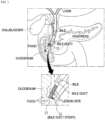
- FIG. 1 is a conceptual diagram illustrating a state in which a bile duct stent according to an embodiment of the present invention is placed.
- FIG. 1 a state in which a bile duct stent 10 according to an embodiment of the present invention is inserted into the bile duct connected to the duodenum is shown.
- the bile duct stent 10 has a cylindrical mesh structure formed using metal wires and has self-elasticity and thus contracts when an external force is applied thereto and expands when the external force is removed.
- the bile duct stent 10 is inserted into a luminal lesion site where a biliary stricture has occurred.
- the bile duct stent 10 expands a lumen by its self-expansile force and maintains the lumen in an expanded state so that the lumen is not narrowed again, and in this way, the bile duct stent 10 serves to facilitate the flow of bile in the duodenum.
- embodiments of the present invention are directed to providing a bile duct stent, in which a backflow-preventing pattern film is formed by weaving a pattern member made of metal wires with a duodenum-side outlet end that is inserted into the bile duct to prevent the backflow of food from the duodenum into the bile duct, and a method of manufacturing the same.
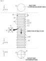
- the metal wires 11 form zigzag patterns by being woven in the circumferential direction X in which the plurality of pins P are disposed at certain intervals, and the stent 10 having the cylindrical body 12 having a mesh structure in which the zigzag patterns formed in the circumferential direction X intersect each other while interfering with each other and are arranged at predetermined intervals W in the longitudinal direction Y is manufactured.
- the cylindrical mesh structure of the stent 10 is shown as having a shape in which rhombic patterns, each with all four sides the same length, are arranged in the circumferential direction X and the longitudinal direction Y of the stent 10.
- the metal wires 11 include first metal wires 11a and second metal wires 11b each of which is able to contract and expand by itself, has flexibility, and is formed to have a unit length.
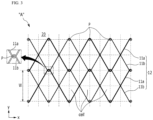
- FIG. 3 a state in which zigzag patterns of the first metal wires 11a and the second metal wires 11b are woven while interfering with each other to form rhombic patterns and are each rotated twice is shown.
- vertical intersection points of a checkerboard shape formed by dotted lines are positions of holes H where the pins P are inserted into the jig 20, and round points at the intersection points indicate a state in which the pins P are installed in the holes H.
- the first metal wires 11a and the second metal wires 11b are woven to manufacture the cylindrical body 12 having the mesh structure.
- first metal wires 11a and the second metal wires 11b are configured to be bent due to the pins P and to only intersect each other without being twisted. In this way, flexibility can be secured, and an easily collapsible structure can be secured upon loading on a catheter afterwards.
- the overall process of manufacturing the stent 10 according to the first configuration not covered by the claimed invention includes a step in which the metal wires 11 are woven through the jig 20 and then heat-treated to form the cylindrical body 12 having elasticity, a step in which the cylindrical body 12 separated from the jig 20 is fitted to a film jig (not illustrated) and coated with a silicone coating solution and then dried to form a silicone film portion 14, and a step in which the threads 15 are woven to the outlet end of the cylindrical body 12 to manufacture the backflow-preventing pattern film 13 having a network structure.
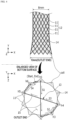
- FIG. 4 illustrates an example of manufacturing a cross-shaped backflow-preventing pattern film using threads according to the first configuration not covered by the claimed invention.
- the stent 10 according to the first configuration not covered by the claimed invention may be manufactured so that a diameter of the outlet end of the cylindrical body (e.g., 10 mm) is greater than a diameter of the central portion thereof (e.g., 8 mm).
- FIG. 4 shows a state in which the silicone film portion 14 is formed on the cylindrical body 12.
- cells made of the metal wires 11 are arranged in a circular shape about the center like petals of a sunflower.
- a hole h is formed in the silicone film portion 14 of each cell formed at the outlet end of the cylindrical body 12.
- the backflow-preventing pattern film 13 may be formed to have a network structure by repeating a process in which the thread 15 fixed by zigzagging to the cell made of the metal wires 11, which is formed in the circumferential direction through any one hole h at a start point, crosses the outlet end one time or more, and passes through another hole h.
- the backflow-preventing pattern film 13 according to the first configuration not covered by the claimed invention is not limited to the cross-shaped backflow-preventing pattern film 13 described above, and backflow-preventing patterns of various other forms may be applied.
- FIG. 5 illustrates an example of implementing various backflow-preventing pattern films using the threads according to the first configuration not covered by the claimed invention.
- the stent 10 may be manufactured to have various backflow-preventing pattern films 13 according to ways in which the thread 15 is utilized and woven to the outlet end (OUT) of the cylindrical body 12.
- the thread 15 forms a network structure of the backflow-preventing pattern.
- the stent 10 has an effect of preventing the backflow of food from the duodenum into the bile duct.
- the backflow-preventing pattern film 13 may be manufactured by stitching and weaving the thread 15 with a needle passing through the silicone film portion 14 formed on the periphery of the outlet end.
- the stent 10 can be easily loaded on a catheter without difficulty of reducing the diameter of the stent 10, and since, during placement of the stent 10, the stent 10 is unfolded especially to have a pattern simultaneously as the cylindrical body 12 develops at a lesion site of the bile duct, the stent 10 has an effect of preventing the backflow of food from the duodenum into the bile duct.
- the pattern member of the backflow-preventing pattern film 13 of the stent 10 can be manufactured by utilizing the metal wires 11 as well as the threads 15, and a method of manufacturing the backflow-preventing pattern film 13 using the metal wires 11 will be described in detail below according to another embodiment.
- FIG. 6 illustrates a state in which a bile duct stent is manufactured using a jig according to a second configuration not covered by the claimed invention.
- a backflow-preventing pattern film 13 using metal wires 11 is formed at the duodenum-side outlet end (OUT) of the cylindrical body 12 that is inserted into the bile duct, and in this way, the backflow of food from the duodenum into the bile duct is prevented.
- the overall process of manufacturing the stent 10 according to the second configuration not covered by the claimed invention is different from that according to the first embodiment in that, in a state in which the metal wires 11 are woven through the jig 20 to form the cylindrical body 12, the backflow-preventing pattern film 13 using the metal wires 11 is formed at the outlet end (OUT) and then heat-treated so that the cylindrical body 12 having elasticity and the backflow-preventing pattern film 13 are simultaneously manufactured. Then, the cylindrical body 12 of the stent 10 that is separated from the jig 20 is fitted to a silicone film jig (not illustrated) and coated with a coating solution and then dried to complete the manufacturing process.
- the backflow-preventing pattern film 13 may be formed as the cross-shaped backflow-preventing pattern film 13#1 in which the metal wires 11 are woven between a pin P and another pin P, which are disposed in the circumferential direction X at one end (that is, a lower end) of the jig 20, and cross the outlet end (OUT) and intersect each other.
- pins P1 to P12 disposed in the circumferential direction X at the lower end of the jig 20 are almost collinear with the outlet end at the one end surface.
- the metal wires 11 are knotted by twisting at least once or more after a first line 13a crossing the outlet end from a first pin P1, which is a start point (Start), is woven on a seventh pin P7 and extends and moves 90° to a tenth pin P10 in the circumferential direction X, and then a second line 13b crossing the outlet end (OUT) from the tenth pin P10 vertically intersects the first line 13a and is woven on a fourth pin P4, which is an end point (End).
- the metal wires 11 may be twisted one time or more with the metal wire 11 forming the outlet end when being woven on each pin P and may be fixed to interfere with each other.
- the backflow-preventing pattern film 13 can be easily manufactured. Further, since it is possible to first manufacture the cylindrical body 12 from the inlet end (IN) to the outlet end (OUT) through the jig 20 and then form the backflow-preventing pattern film 13 using the metal wires 11 at the outlet end (OUT) without a pause, there is an advantage in that the manufacturing process is reduced.
- the stent 10 When the task of weaving the metal wires 11 to the backflow-preventing pattern film 13 is completed on the jig 20 as described above, the stent 10 may be separated from the jig 20 and undergo washing and sterilizing processes and then may be shipped out as a finished product.
- a process of coating the cylindrical body 12 with a coating material and forming the film portion 14 may be further performed on the stent 10, and then the stent 10 may be shipped out as a covered-type metal stent product.
- the film portion 14 may be formed by coating the cylindrical body 12 with a coating solution such as polyurethane in a state in which the stent 10 is heated to a certain temperature.
- the backflow-preventing pattern film 13 using the metal wires 11 according to the second configuration not covered by the claimed invention is not limited to the cross-shaped backflow-preventing pattern film 13#1 described above, and backflow-preventing patterns of various other forms may be applied.
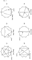
- FIG. 7 illustrates an example of implementing various backflow-preventing pattern films using metal wires according to the configuration not covered by the claimed invention.
- the backflow-preventing pattern film 13 according to the second configuration not covered by the claimed invention is not limited to the cross-shaped backflow-preventing pattern film 13#1 and may also be formed as the zigzag-shaped backflow-preventing pattern film 13#3, the polygonal backflow-preventing pattern film 13#4, and the star-shaped backflow-preventing pattern film 13#5 in which the metal wire 11 is woven between a pin P and another pin P and crosses the outlet end.
- the zigzag-shaped backflow-preventing pattern film 13#3 may be formed by the metal wire 11 being knotted after crossing the outlet end from an eleventh pin P11, which is a start point (Start), and being woven on a third pin P3, and then sequentially crossing the outlet end and being woven on a ninth pin P9, crossing the outlet end and being woven on a fifth pin P5, and crossing the outlet end and being woven on the eleventh pin P11, which is an end point (End).
- the start point (Start) and the end point (End) are the same.
- a triangular backflow-preventing pattern film may be formed by the metal wire 11 being knotted after crossing the outlet end from the first pin P1, which is a start point (Start), and being woven on the ninth pin P9, and then sequentially crossing the outlet end and being woven on the fifth pin P5, and crossing the outlet end and being woven on the first pin P1, which is an end point (End).
- the polygonal backflow-preventing pattern film 13#4 may be formed in various other polygonal shapes such as a quadrangular shape in addition to being formed in a triangular shape, and the start point (Start) and the end point (End) are the same.
- the star-shaped backflow-preventing pattern film 13#5 may be formed by the metal wire 11 being knotted after crossing the outlet end from the first pin P1, which is the start point (Start), and being woven on an eighth pin P8, and then sequentially crossing the outlet end and being woven on the third pin P3, crossing the outlet end and being woven on the eleventh pin P11, crossing the outlet end and being woven on a sixth pin P6, and crossing the outlet end and being woven on the first pin P1, which is the end point (End).
- the stent 10 may be manufactured to have various backflow-preventing pattern films 13 according to ways in which the jig 20 is utilized and the metal wire 11 is woven to the outlet end (OUT) of the cylindrical body 12. Also, during placement of the stent 10, in a state in which the stent 10 is developed at a lesion site in the bile duct, the stent 10 has an effect of, by the backflow-preventing pattern film 13, preventing the backflow of food from the duodenum into the bile duct.
- the stent 10 may be manufactured to have a denser backflow-preventing pattern film 13 with an increase in the number of lines of the metal wire 11 that connect a pin P and another pin P and cross the outlet end (OUT). This will be described next according to a third embodiment.
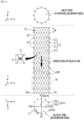
- FIG. 8 illustrates a state in which a bile duct stent is manufactured using a jig having a vertical pin formed thereon according to the present invention.
- the jig 20 includes at least one vertical pin Py formed on a lower surface 21 that corresponds to the outlet end (OUT) of the stent 10.
- the metal wires 11 are sequentially woven between the pins P, which are disposed in the circumferential direction X on the lower end of the jig 20, and the vertical pin Py to form a radial backflow-preventing pattern film 13#6 on the outlet end of the cylindrical body 12.
- the radial backflow-preventing pattern film 13#6 is formed by, in the clockwise direction, the metal wire 11 being woven on the vertical pin Py at the center from a twelfth pin P12 which is a start point (Start) and then being woven on a second pin P2 and extending and moving to the fourth pin P4 in the circumferential direction X (steps S1, S2, and S3), and then being woven on the vertical pin Py at the center from the fourth pin P4 and then being woven on the sixth pin P6 and extending and moving to the eighth pin P8 in the circumferential direction X (steps S4, S5, and S6), and then being woven on the vertical pin Py at the center from the eighth pin P8 and then being woven on the tenth pin P10 which is an end point (End).
- steps S3 and S5 for extending and moving may be omitted according to changes in the manufacturing method, and a triangular line connecting a pair of pins and the vertical pin Py may be independently formed.
- the metal wires 11 having the three reciprocating lines woven through the vertical pin Py may be fixed by intersecting each other in a bent state.
- the backflow-preventing pattern film 13 may be manufactured to be denser with an increase in the number of lines of the metal wire 11 that cross the outlet end (OUT).
- the backflow-preventing pattern film 13 is not limited to the radial backflow-preventing pattern film 13#6 described above and may be manufactured to have other dense radial backflow-preventing patterns according to various modifications.
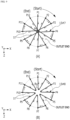
- FIG. 9 illustrates various forms of dense radial backflow-preventing pattern films according to the third embodiment.
- a first radial backflow-preventing pattern film 13#7 which is denser than the above-described radial backflow-preventing pattern film 13#6 due to an increase in the number of lines of the metal wire 11 woven on the vertical pin Py of the jig 20 of the stent 10 is shown.
- the metal wires 11 are more densely sequentially woven between the pins P, which are disposed in the circumferential direction X on the lower end of the jig 20, and the vertical pin Py to form six reciprocating lines that are woven through the vertical pin Py.
- the six reciprocating lines may be woven with each other and fixed.
- a second radial backflow-preventing pattern film 13#8 is shown which is densely formed by a circular array of vertical pins Py being formed around the center of the lower surface 21 of the jig 20 and the metal wires 11 being woven therethrough.
- the metal wires 11 may be sequentially woven between six pins P, which are disposed in the circumferential direction X at the lower end of the jig 20, and the array of vertical pins Py corresponding thereto to form dense the second radial backflow-preventing pattern film 13#8 on the outlet end of the cylindrical body 12.
- the second radial backflow-preventing pattern film 13#8 is not covered by the invention as defined in the appended claims.
- optimal conditions for a bile duct stent in consideration of clinically important physical factors include high flexibility, an excellent radial expansile force, conformability with low axial force to allow the stent to maintain its shape while being bent along the flexion of the bile duct, minimization of a degree of shortening in order to place the stent at a correct position at a lesion site, reduction of a size of a cell between metal wires to reduce growth in a tumor, durability, and a high level of ease of loading the stent on a catheter which is a stent transfer system.
- the ease of loading the stent on a catheter relates to loading the stent 10 in a diameter-reduced state on a catheter to facilitate placement of the stent 10.
- a structure in which it is difficult to physically reduce the diameter of the stent 10 has a disadvantage in that the level of ease of loading is low and a diameter of a catheter is increased, which makes it difficult to insert the catheter into the bile duct and adversely affects the operation carried out by a surgeon.
- the bile duct stent 10 according to the third embodiment of the present invention has a characteristic in that the radial backflow-preventing pattern films 13 of various shapes are formed by the metal wires 11 crossing the outlet end. Since such a characteristic may be disadvantageous for diameter reduction, the level of ease of loading the stent 10 on a catheter may be considered.
- a bile duct stent 10 with a structure in which the level of ease of loading on a catheter is improved will be described next according to a fourth embodiment of the present invention.
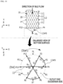
- FIG. 10 illustrates a state in which a bile duct stent is manufactured using a conical jig according to the present invention.
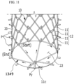
- FIG. 11 is a perspective view illustrating a conical backflow-preventing pattern film according to the present invention.
- the jig 20 includes an outer peripheral surface 22, which is inclined in a conical shape at an outlet end (OUT) of the stent 10, and a vertical pin Py fixed to a vertex of the center of the outer peripheral surface 22.
- a conical backflow-preventing pattern film 13#9 is formed in which the metal wires 11 are sequentially woven between the pins P, which are disposed in the circumferential direction X on the lower end of the jig 20, and the vertical pin Py to form a radial pattern, and the center protrudes due to the outer peripheral surface 22 inclined in the conical shape.
- the process of manufacturing the radial backflow-preventing pattern film 13#6 that has been described above with reference to FIG. 8 may be referenced.
- the conical backflow-preventing pattern film 13#9 may be manufactured to have a denser structure by increasing the number of times the metal wires 11 are woven as in FIG. 9A .
- the lines of the metal wires 11 forming the conical backflow-preventing pattern film 13#9 form a triangular structure as bent portions 11c are formed due to the vertical pin Py and form an inclined structure in which the bent portions 11c intersect and radiate while interfering with each other.
- FIG. 12 illustrates an example in which the stent according to the configuration not covered by the claimed invention is placed at a lesion site of the bile duct.
- FIG. 12A shows a state in which the stent 10 according to the configuration not covered by the claimed invention is in a diameter-reduced state, loaded on a catheter, and moved past a lesion site in the bile duct.
- the conical backflow-preventing pattern film 13#9 is configured so that, when the stent 10 is loaded in an inner diameter of a catheter for stent placement, a diameter of the cylindrical body 12 is reduced due to an external pressure, and simultaneously, the bent portions 11c are folded without any physical resistance. Thus, there is an effect of facilitating loading of the stent 10 on the catheter.
- FIG. 12B shows a state in which the stent 10 exposed due to the catheter retracting is expanded, causing the lesion site in the bile duct to be expanded.
- the conical backflow-preventing pattern film 13#9 is expanded at a duodenum-side passage of the bile duct to prevent the backflow of food from the duodenum into the bile duct and discharge bile, which flows in the bile duct, to the duodenum.
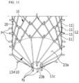
- FIG. 13 is a perspective view illustrating a truncated conical backflow-preventing pattern film according to the configuration not covered by the claimed invention.
- the jig 20 according to the configuration not covered by the claimed invention includes a truncated cone outer peripheral surface 23a, which is inclined, and a truncated cone lower surface 23b formed at an outlet end (OUT) of the stent 10 in order to constitute a truncated conical structure which is broad at the top and gets narrower toward the bottom and also includes a circular array of vertical pins Py formed around the center of the truncated cone lower surface 23b.
- a truncated conical backflow-preventing pattern film 13#10 may be formed on the outlet end of the cylindrical body 12.
- the bent portion 11c may be formed due to the vertical pin Py, and the bent portions 11c may radiate and form an inclined structure without interfering with each other.
- backflow-preventing pattern films of various dense patterns can be easily manufactured with a single line of thread or metal wire on an outlet end of the bile duct stent, and by configuring the backflow-preventing pattern films using nylon threads or metal wires, there is an effect of securing durability.
- the embodiments of the present invention may be implemented through programs for realizing functions corresponding to configurations of the embodiments of the present invention, recording media in which the programs are recorded, etc.
Landscapes
- Health & Medical Sciences (AREA)
- Engineering & Computer Science (AREA)
- General Health & Medical Sciences (AREA)
- Heart & Thoracic Surgery (AREA)
- Vascular Medicine (AREA)
- Biomedical Technology (AREA)
- Veterinary Medicine (AREA)
- Public Health (AREA)
- Life Sciences & Earth Sciences (AREA)
- Animal Behavior & Ethology (AREA)
- Transplantation (AREA)
- Oral & Maxillofacial Surgery (AREA)
- Cardiology (AREA)
- Surgery (AREA)
- Epidemiology (AREA)
- Gastroenterology & Hepatology (AREA)
- Pulmonology (AREA)
- Chemical & Material Sciences (AREA)
- Inorganic Chemistry (AREA)
- Mechanical Engineering (AREA)
- Media Introduction/Drainage Providing Device (AREA)
- Prostheses (AREA)
Claims (5)
- Gallengangstent umfassend:einen zylindrischen Körper (12) mit einer Maschenstruktur, die durch zickzackförmige Anordnung von Metalldrähten (11) aus einer Formgedächtnislegierung auf einer Mehrzahl von Stiften gebildet ist, die jeweils in einer Umfangsrichtung (X) und einer Längsrichtung (Y) einer zylindrischen Spanvorrichtung (20) angeordnet sind; undeinen rückflussverhindernden Musterfilm (13), in dem die Metalldrähte (11) auf Stiften (P) gewebt sind, die in der Umfangsrichtung (X) an einem unteren Ende der Spannvorrichtung (20) angeordnet sind, und die Metalldrähte (11) ein Auslassende des zylindrischen Körpers (12) ein- oder mehrmals kreuzen, um eine Netzwerkstruktur zu bilden,wobei der rückflussverhindernde Musterfilm (13) als ein radialer rückflussverhindernder Musterfilm gebildet ist, in dem die Metalldrähte (11) nacheinander auf den Stiften (P), die in der Umfangsrichtung (X) an einem unteren Ende der Spannvorrichtung (20) angeordnet sind, und auf einem einzelnen vertikalen Stift (Py) gewebt sind, der in der Mitte einer unteren Oberfläche der Spannvorrichtung (20) angeordnet ist.
- Gallengangstent nach Anspruch 1, wobei, in dem radialen rückflussverhindernden Musterfilm, mehrere Reihen von auf dem vertikalen Stift (Py) gewebten Metalldrähten befestigt sind, indem sie sich in einem gebogenen Zustand kreuzen.
- Gallengangstent nach Anspruch 1, wobei der rückflussverhindernde Musterfilm als ein konischer rückflussverhindernder Musterfilm gebildet ist, in dem eine geneigte äußere Umfangsfläche mit einer konischen Form an einer unteren Oberfläche der Spannvorrichtung gebildet ist, der vertikale Stift (Py) an einem Scheitelpunkt in der Mitte der äußeren Umfangsfläche befestigt ist, die Metalldrähte nacheinander zwischen dem vertikalen Stift (Py) und den Stiften (P) gewebt sind, die in der Umfangsrichtung (X) am unteren Ende der Spannvorrichtung angeordnet sind, um ein radiales Muster zu bilden, und die Mitte aufgrund der geneigten äußeren Umfangsfläche mit der konischen Form hervorsteht.
- Verfahren zur Herstellung eines Gallengangstents unter Verwendung einer Spannvorrichtung, wobei das Verfahren umfasst:a) Bilden eines zylindrischen Körpers (12) mit einer Maschenstruktur durch Zickzackanordnung von Metalldrähten (11) aus einem Formgedächtnislegierungsmaterial auf einer Mehrzahl von Stiften, die jeweils in einer Umfangsrichtung (X) und einer Längsrichtung (Y) einer zylindrischen Spannvorrichtung (20) angeordnet sind; undb) Bilden eines rückflussverhindernden Musterfilms (13) mit einer Netzwerkstruktur, indem bewirkt wird, dass ein Musterelement aus Metalldrähten (11) ein Auslassende eines Durchgangs des zylindrischen Körpers (12) ein- oder mehrmals kreuzt,wobei der Schritt b) ein Bilden des rückflussverhindernden Musterfilms als ein konischer rückflussverhindernder Musterfilm (13#9) umfasst, in dem eine untere Oberfläche der Spannvorrichtung (20) eine geneigte äußere Umfangsoberfläche mit einer konischen Form und einem vertikalen Stift (Py), der an einem Scheitelpunkt in der Mitte der äußeren Umfangsoberfläche befestigt ist, und Stifte (P) aufweist, die in der Umfangsrichtung (X) am unteren Ende der Spannvorrichtung (20) angeordnet sind, die Metalldrähte (11) nacheinander zwischen den Stiften (P) und dem vertikalen Stift (Py) verwoben sind, um ein radiales Muster zu bilden, und die Mitte aufgrund der geneigten äußeren Umfangsoberfläche mit der konischen Form hervorsteht.
- Verfahren nach Anspruch 4, wobei der Schritt b) umfasst:einen Schritt, bei dem der Metalldraht von einem ersten Stift (P1), der ein Startpunkt ist, zu dem vertikalen Stift (Py) in der Mitte gewebt wird, um einen gebogenen Abschnitt zu bilden, auf einen zweiten Stift gewebt wird und sich dann in einer Umfangsrichtung zu einem dritten Stift erstreckt und bewegt;einen Schritt, bei dem der Metalldraht von dem dritten Stift zu dem vertikalen Stift (Py) in der Mitte gewebt wird, um einen gebogenen Abschnitt zu bilden, auf einen vierten Stift gewebt wird und sich dann in der Umfangsrichtung zu einem fünften Stift erstreckt und bewegt; undeinen Schritt, bei dem der Metalldraht von dem fünften Stift zu dem vertikalen Stift (Py) in der Mitte gewebt wird, um einen gebogenen Abschnitt zu bilden, auf einen sechsten Stift, der ein Endpunkt ist, gewebt wird und dann durch zumindest einmaliges oder mehrmaliges Verdrehen verknotet wird,wobei der erste Stift bis zum sechsten Stift die Stifte (P) sind, die in der Umfangsrichtung (X) am unteren Ende der Spannvorrichtung angeordnet sind.
Applications Claiming Priority (2)
| Application Number | Priority Date | Filing Date | Title |
|---|---|---|---|
| KR1020200046815A KR102409245B1 (ko) | 2020-04-17 | 2020-04-17 | 담관용 스텐트 및 그 제작 방법 |
| PCT/KR2021/004125 WO2021210821A1 (ko) | 2020-04-17 | 2021-04-02 | 담관용 스텐트 및 그 제작 방법 |
Publications (3)
| Publication Number | Publication Date |
|---|---|
| EP4137101A1 EP4137101A1 (de) | 2023-02-22 |
| EP4137101A4 EP4137101A4 (de) | 2023-09-13 |
| EP4137101B1 true EP4137101B1 (de) | 2024-11-27 |
Family
ID=78085030
Family Applications (1)
| Application Number | Title | Priority Date | Filing Date |
|---|---|---|---|
| EP21788864.3A Active EP4137101B1 (de) | 2020-04-17 | 2021-04-02 | Gallengangstent und herstellungsverfahren davon |
Country Status (6)
| Country | Link |
|---|---|
| US (1) | US20220304796A1 (de) |
| EP (1) | EP4137101B1 (de) |
| JP (1) | JP7385043B2 (de) |
| KR (1) | KR102409245B1 (de) |
| CN (1) | CN114901220B (de) |
| WO (1) | WO2021210821A1 (de) |
Families Citing this family (3)
| Publication number | Priority date | Publication date | Assignee | Title |
|---|---|---|---|---|
| CN115553972B (zh) * | 2022-10-19 | 2023-10-20 | 常州乐奥医疗科技股份有限公司 | 一种胆道支架制造方法及胆道支架 |
| CN115889619A (zh) * | 2022-10-27 | 2023-04-04 | 常州乐奥医疗科技股份有限公司 | 一种胆道支架制造夹具及胆道支架制造方法 |
| CN116350411B (zh) * | 2023-04-11 | 2024-08-09 | 江苏唯德康医疗科技有限公司 | 一种支架编织方法及使用该方法编织的支架 |
Family Cites Families (9)
| Publication number | Priority date | Publication date | Assignee | Title |
|---|---|---|---|---|
| KR0170220B1 (ko) | 1996-08-31 | 1999-03-20 | 김광호 | 역류 방지수단을 갖춘 스텐트 |
| US6790237B2 (en) * | 2001-10-09 | 2004-09-14 | Scimed Life Systems, Inc. | Medical stent with a valve and related methods of manufacturing |
| KR100442330B1 (ko) * | 2002-09-03 | 2004-07-30 | 주식회사 엠아이텍 | 스텐트 및 이 스텐트의 제조방법 |
| KR100561713B1 (ko) * | 2003-05-23 | 2006-03-20 | (주) 태웅메디칼 | 가변상태 유지형 스텐트의 제조방법과 이에 의해 제조된가변상태 유지형 스텐트 |
| KR101006972B1 (ko) | 2009-02-19 | 2011-01-12 | 신경민 | 음식물 역류방지와 체내 분해가 가능한 스텐트 |
| JP5186042B2 (ja) * | 2009-07-10 | 2013-04-17 | テウーン メディカル カンパニー リミティッド | ステント |
| JP6179949B2 (ja) | 2012-01-30 | 2017-08-16 | 川澄化学工業株式会社 | 胆管ステント |
| KR20140094144A (ko) * | 2013-01-21 | 2014-07-30 | 주식회사 엠아이텍 | 이탈 방지용 스텐트, 제조 장치 및 그 제조 방법 |
| KR101996524B1 (ko) * | 2017-08-02 | 2019-07-04 | (주)태웅메디칼 | 담도용 스텐트 |
-
2020
- 2020-04-17 KR KR1020200046815A patent/KR102409245B1/ko active Active
-
2021
- 2021-04-02 EP EP21788864.3A patent/EP4137101B1/de active Active
- 2021-04-02 CN CN202180007500.6A patent/CN114901220B/zh active Active
- 2021-04-02 JP JP2022537361A patent/JP7385043B2/ja active Active
- 2021-04-02 WO PCT/KR2021/004125 patent/WO2021210821A1/ko not_active Ceased
-
2022
- 2022-06-15 US US17/840,626 patent/US20220304796A1/en active Pending
Also Published As
| Publication number | Publication date |
|---|---|
| JP7385043B2 (ja) | 2023-11-21 |
| KR20210128756A (ko) | 2021-10-27 |
| CN114901220A (zh) | 2022-08-12 |
| JP2023508863A (ja) | 2023-03-06 |
| EP4137101A4 (de) | 2023-09-13 |
| US20220304796A1 (en) | 2022-09-29 |
| EP4137101A1 (de) | 2023-02-22 |
| WO2021210821A1 (ko) | 2021-10-21 |
| KR102409245B1 (ko) | 2022-06-15 |
| CN114901220B (zh) | 2025-05-06 |
Similar Documents
| Publication | Publication Date | Title |
|---|---|---|
| US20220304796A1 (en) | Bile duct stent and method of manufacturing the same | |
| RU2452432C2 (ru) | Вживляемое устройство | |
| JP4669699B2 (ja) | 網目状ステントおよびその製造方法 | |
| JP7603160B2 (ja) | 向上した展開特性を有するステント | |
| CN110520076B (zh) | 血管植入物 | |
| EP2344069B1 (de) | Implantierbare prothese mit regionen verringerter dichte | |
| JP2006506168A5 (de) | ||
| CN107106310B (zh) | 具有柔性铰链的支架 | |
| JP2003513748A (ja) | 多部分フィラメント状管腔内ステント | |
| JP2010517703A (ja) | 血管移植片およびそれを加工する方法 | |
| KR102196226B1 (ko) | 스텐트 및 그 제작 방법 | |
| EP4034037B1 (de) | Künstliche herzklappe | |
| JP6688125B2 (ja) | 高柔軟性ステント | |
| US20250213345A1 (en) | Stent with features to reduce food impaction | |
| JP6734097B2 (ja) | 高柔軟性ステント |
Legal Events
| Date | Code | Title | Description |
|---|---|---|---|
| STAA | Information on the status of an ep patent application or granted ep patent |
Free format text: STATUS: THE INTERNATIONAL PUBLICATION HAS BEEN MADE |
|
| PUAI | Public reference made under article 153(3) epc to a published international application that has entered the european phase |
Free format text: ORIGINAL CODE: 0009012 |
|
| STAA | Information on the status of an ep patent application or granted ep patent |
Free format text: STATUS: REQUEST FOR EXAMINATION WAS MADE |
|
| 17P | Request for examination filed |
Effective date: 20220706 |
|
| AK | Designated contracting states |
Kind code of ref document: A1 Designated state(s): AL AT BE BG CH CY CZ DE DK EE ES FI FR GB GR HR HU IE IS IT LI LT LU LV MC MK MT NL NO PL PT RO RS SE SI SK SM TR |
|
| DAV | Request for validation of the european patent (deleted) | ||
| DAX | Request for extension of the european patent (deleted) | ||
| STAA | Information on the status of an ep patent application or granted ep patent |
Free format text: STATUS: EXAMINATION IS IN PROGRESS |
|
| A4 | Supplementary search report drawn up and despatched |
Effective date: 20230810 |
|
| RIC1 | Information provided on ipc code assigned before grant |
Ipc: A61B 17/00 20060101ALN20230804BHEP Ipc: B21F 45/00 20060101ALI20230804BHEP Ipc: A61F 2/00 20060101ALI20230804BHEP Ipc: A61L 31/14 20060101ALI20230804BHEP Ipc: A61L 31/02 20060101ALI20230804BHEP Ipc: A61F 2/04 20130101ALI20230804BHEP Ipc: A61F 2/856 20130101ALI20230804BHEP Ipc: A61F 2/90 20130101AFI20230804BHEP |
|
| 17Q | First examination report despatched |
Effective date: 20230823 |
|
| GRAP | Despatch of communication of intention to grant a patent |
Free format text: ORIGINAL CODE: EPIDOSNIGR1 |
|
| STAA | Information on the status of an ep patent application or granted ep patent |
Free format text: STATUS: GRANT OF PATENT IS INTENDED |
|
| RIC1 | Information provided on ipc code assigned before grant |
Ipc: A61B 17/00 20060101ALN20240620BHEP Ipc: B21F 45/00 20060101ALI20240620BHEP Ipc: A61F 2/00 20060101ALI20240620BHEP Ipc: A61L 31/14 20060101ALI20240620BHEP Ipc: A61L 31/02 20060101ALI20240620BHEP Ipc: A61F 2/04 20130101ALI20240620BHEP Ipc: A61F 2/856 20130101ALI20240620BHEP Ipc: A61F 2/90 20130101AFI20240620BHEP |
|
| INTG | Intention to grant announced |
Effective date: 20240703 |
|
| GRAS | Grant fee paid |
Free format text: ORIGINAL CODE: EPIDOSNIGR3 |
|
| GRAA | (expected) grant |
Free format text: ORIGINAL CODE: 0009210 |
|
| STAA | Information on the status of an ep patent application or granted ep patent |
Free format text: STATUS: THE PATENT HAS BEEN GRANTED |
|
| AK | Designated contracting states |
Kind code of ref document: B1 Designated state(s): AL AT BE BG CH CY CZ DE DK EE ES FI FR GB GR HR HU IE IS IT LI LT LU LV MC MK MT NL NO PL PT RO RS SE SI SK SM TR |
|
| REG | Reference to a national code |
Ref country code: GB Ref legal event code: FG4D |
|
| REG | Reference to a national code |
Ref country code: CH Ref legal event code: EP |
|
| REG | Reference to a national code |
Ref country code: IE Ref legal event code: FG4D |
|
| REG | Reference to a national code |
Ref country code: DE Ref legal event code: R096 Ref document number: 602021022520 Country of ref document: DE |
|
| REG | Reference to a national code |
Ref country code: LT Ref legal event code: MG9D |
|
| REG | Reference to a national code |
Ref country code: NL Ref legal event code: MP Effective date: 20241127 |
|
| PG25 | Lapsed in a contracting state [announced via postgrant information from national office to epo] |
Ref country code: IS Free format text: LAPSE BECAUSE OF FAILURE TO SUBMIT A TRANSLATION OF THE DESCRIPTION OR TO PAY THE FEE WITHIN THE PRESCRIBED TIME-LIMIT Effective date: 20250327 Ref country code: PT Free format text: LAPSE BECAUSE OF FAILURE TO SUBMIT A TRANSLATION OF THE DESCRIPTION OR TO PAY THE FEE WITHIN THE PRESCRIBED TIME-LIMIT Effective date: 20250327 Ref country code: HR Free format text: LAPSE BECAUSE OF FAILURE TO SUBMIT A TRANSLATION OF THE DESCRIPTION OR TO PAY THE FEE WITHIN THE PRESCRIBED TIME-LIMIT Effective date: 20241127 |
|
| PG25 | Lapsed in a contracting state [announced via postgrant information from national office to epo] |
Ref country code: FI Free format text: LAPSE BECAUSE OF FAILURE TO SUBMIT A TRANSLATION OF THE DESCRIPTION OR TO PAY THE FEE WITHIN THE PRESCRIBED TIME-LIMIT Effective date: 20241127 Ref country code: NL Free format text: LAPSE BECAUSE OF FAILURE TO SUBMIT A TRANSLATION OF THE DESCRIPTION OR TO PAY THE FEE WITHIN THE PRESCRIBED TIME-LIMIT Effective date: 20241127 |
|
| REG | Reference to a national code |
Ref country code: AT Ref legal event code: MK05 Ref document number: 1745017 Country of ref document: AT Kind code of ref document: T Effective date: 20241127 |
|
| PG25 | Lapsed in a contracting state [announced via postgrant information from national office to epo] |
Ref country code: BG Free format text: LAPSE BECAUSE OF FAILURE TO SUBMIT A TRANSLATION OF THE DESCRIPTION OR TO PAY THE FEE WITHIN THE PRESCRIBED TIME-LIMIT Effective date: 20241127 |
|
| PG25 | Lapsed in a contracting state [announced via postgrant information from national office to epo] |
Ref country code: ES Free format text: LAPSE BECAUSE OF FAILURE TO SUBMIT A TRANSLATION OF THE DESCRIPTION OR TO PAY THE FEE WITHIN THE PRESCRIBED TIME-LIMIT Effective date: 20241127 |
|
| PG25 | Lapsed in a contracting state [announced via postgrant information from national office to epo] |
Ref country code: NO Free format text: LAPSE BECAUSE OF FAILURE TO SUBMIT A TRANSLATION OF THE DESCRIPTION OR TO PAY THE FEE WITHIN THE PRESCRIBED TIME-LIMIT Effective date: 20250227 |
|
| PG25 | Lapsed in a contracting state [announced via postgrant information from national office to epo] |
Ref country code: LV Free format text: LAPSE BECAUSE OF FAILURE TO SUBMIT A TRANSLATION OF THE DESCRIPTION OR TO PAY THE FEE WITHIN THE PRESCRIBED TIME-LIMIT Effective date: 20241127 Ref country code: GR Free format text: LAPSE BECAUSE OF FAILURE TO SUBMIT A TRANSLATION OF THE DESCRIPTION OR TO PAY THE FEE WITHIN THE PRESCRIBED TIME-LIMIT Effective date: 20250228 Ref country code: AT Free format text: LAPSE BECAUSE OF FAILURE TO SUBMIT A TRANSLATION OF THE DESCRIPTION OR TO PAY THE FEE WITHIN THE PRESCRIBED TIME-LIMIT Effective date: 20241127 |
|
| PG25 | Lapsed in a contracting state [announced via postgrant information from national office to epo] |
Ref country code: PL Free format text: LAPSE BECAUSE OF FAILURE TO SUBMIT A TRANSLATION OF THE DESCRIPTION OR TO PAY THE FEE WITHIN THE PRESCRIBED TIME-LIMIT Effective date: 20241127 |
|
| PG25 | Lapsed in a contracting state [announced via postgrant information from national office to epo] |
Ref country code: RS Free format text: LAPSE BECAUSE OF FAILURE TO SUBMIT A TRANSLATION OF THE DESCRIPTION OR TO PAY THE FEE WITHIN THE PRESCRIBED TIME-LIMIT Effective date: 20250227 |
|
| PG25 | Lapsed in a contracting state [announced via postgrant information from national office to epo] |
Ref country code: SM Free format text: LAPSE BECAUSE OF FAILURE TO SUBMIT A TRANSLATION OF THE DESCRIPTION OR TO PAY THE FEE WITHIN THE PRESCRIBED TIME-LIMIT Effective date: 20241127 |
|
| PGFP | Annual fee paid to national office [announced via postgrant information from national office to epo] |
Ref country code: DE Payment date: 20250417 Year of fee payment: 5 |
|
| PG25 | Lapsed in a contracting state [announced via postgrant information from national office to epo] |
Ref country code: DK Free format text: LAPSE BECAUSE OF FAILURE TO SUBMIT A TRANSLATION OF THE DESCRIPTION OR TO PAY THE FEE WITHIN THE PRESCRIBED TIME-LIMIT Effective date: 20241127 |
|
| PGFP | Annual fee paid to national office [announced via postgrant information from national office to epo] |
Ref country code: GB Payment date: 20250423 Year of fee payment: 5 |
|
| PGFP | Annual fee paid to national office [announced via postgrant information from national office to epo] |
Ref country code: IT Payment date: 20250430 Year of fee payment: 5 |
|
| PG25 | Lapsed in a contracting state [announced via postgrant information from national office to epo] |
Ref country code: EE Free format text: LAPSE BECAUSE OF FAILURE TO SUBMIT A TRANSLATION OF THE DESCRIPTION OR TO PAY THE FEE WITHIN THE PRESCRIBED TIME-LIMIT Effective date: 20241127 |
|
| PGFP | Annual fee paid to national office [announced via postgrant information from national office to epo] |
Ref country code: FR Payment date: 20250428 Year of fee payment: 5 |
|
| PG25 | Lapsed in a contracting state [announced via postgrant information from national office to epo] |
Ref country code: RO Free format text: LAPSE BECAUSE OF FAILURE TO SUBMIT A TRANSLATION OF THE DESCRIPTION OR TO PAY THE FEE WITHIN THE PRESCRIBED TIME-LIMIT Effective date: 20241127 |
|
| PG25 | Lapsed in a contracting state [announced via postgrant information from national office to epo] |
Ref country code: SK Free format text: LAPSE BECAUSE OF FAILURE TO SUBMIT A TRANSLATION OF THE DESCRIPTION OR TO PAY THE FEE WITHIN THE PRESCRIBED TIME-LIMIT Effective date: 20241127 |
|
| PG25 | Lapsed in a contracting state [announced via postgrant information from national office to epo] |
Ref country code: CZ Free format text: LAPSE BECAUSE OF FAILURE TO SUBMIT A TRANSLATION OF THE DESCRIPTION OR TO PAY THE FEE WITHIN THE PRESCRIBED TIME-LIMIT Effective date: 20241127 |
|
| REG | Reference to a national code |
Ref country code: DE Ref legal event code: R097 Ref document number: 602021022520 Country of ref document: DE |
|
| PG25 | Lapsed in a contracting state [announced via postgrant information from national office to epo] |
Ref country code: SE Free format text: LAPSE BECAUSE OF FAILURE TO SUBMIT A TRANSLATION OF THE DESCRIPTION OR TO PAY THE FEE WITHIN THE PRESCRIBED TIME-LIMIT Effective date: 20241127 |
|
| PLBE | No opposition filed within time limit |
Free format text: ORIGINAL CODE: 0009261 |
|
| STAA | Information on the status of an ep patent application or granted ep patent |
Free format text: STATUS: NO OPPOSITION FILED WITHIN TIME LIMIT |
|
| REG | Reference to a national code |
Ref country code: CH Ref legal event code: L10 Free format text: ST27 STATUS EVENT CODE: U-0-0-L10-L00 (AS PROVIDED BY THE NATIONAL OFFICE) Effective date: 20251008 |
|
| 26N | No opposition filed |
Effective date: 20250828 |
|
| REG | Reference to a national code |
Ref country code: CH Ref legal event code: H13 Free format text: ST27 STATUS EVENT CODE: U-0-0-H10-H13 (AS PROVIDED BY THE NATIONAL OFFICE) Effective date: 20251125 |
|
| PG25 | Lapsed in a contracting state [announced via postgrant information from national office to epo] |
Ref country code: LU Free format text: LAPSE BECAUSE OF NON-PAYMENT OF DUE FEES Effective date: 20250402 |
|
| PG25 | Lapsed in a contracting state [announced via postgrant information from national office to epo] |
Ref country code: MC Free format text: LAPSE BECAUSE OF FAILURE TO SUBMIT A TRANSLATION OF THE DESCRIPTION OR TO PAY THE FEE WITHIN THE PRESCRIBED TIME-LIMIT Effective date: 20241127 |
|
| REG | Reference to a national code |
Ref country code: BE Ref legal event code: MM Effective date: 20250430 |
|
| PG25 | Lapsed in a contracting state [announced via postgrant information from national office to epo] |
Ref country code: BE Free format text: LAPSE BECAUSE OF NON-PAYMENT OF DUE FEES Effective date: 20250430 |
|
| PG25 | Lapsed in a contracting state [announced via postgrant information from national office to epo] |
Ref country code: CH Free format text: LAPSE BECAUSE OF NON-PAYMENT OF DUE FEES Effective date: 20250430 |