EP4136992B1 - Heizanordnung, zerstäuber und elektronische zerstäubungsvorrichtung - Google Patents
Heizanordnung, zerstäuber und elektronische zerstäubungsvorrichtung Download PDFInfo
- Publication number
- EP4136992B1 EP4136992B1 EP20933090.1A EP20933090A EP4136992B1 EP 4136992 B1 EP4136992 B1 EP 4136992B1 EP 20933090 A EP20933090 A EP 20933090A EP 4136992 B1 EP4136992 B1 EP 4136992B1
- Authority
- EP
- European Patent Office
- Prior art keywords
- liquid
- heating assembly
- vaporization
- preheating
- preheating portion
- Prior art date
- Legal status (The legal status is an assumption and is not a legal conclusion. Google has not performed a legal analysis and makes no representation as to the accuracy of the status listed.)
- Active
Links
Images


Classifications
-
- A—HUMAN NECESSITIES
- A24—TOBACCO; CIGARS; CIGARETTES; SIMULATED SMOKING DEVICES; SMOKERS' REQUISITES
- A24F—SMOKERS' REQUISITES; MATCH BOXES; SIMULATED SMOKING DEVICES
- A24F40/00—Electrically operated smoking devices; Component parts thereof; Manufacture thereof; Maintenance or testing thereof; Charging means specially adapted therefor
- A24F40/40—Constructional details, e.g. connection of cartridges and battery parts
- A24F40/46—Shape or structure of electric heating means
-
- A—HUMAN NECESSITIES
- A24—TOBACCO; CIGARS; CIGARETTES; SIMULATED SMOKING DEVICES; SMOKERS' REQUISITES
- A24F—SMOKERS' REQUISITES; MATCH BOXES; SIMULATED SMOKING DEVICES
- A24F40/00—Electrically operated smoking devices; Component parts thereof; Manufacture thereof; Maintenance or testing thereof; Charging means specially adapted therefor
- A24F40/10—Devices using liquid inhalable precursors
-
- A—HUMAN NECESSITIES
- A24—TOBACCO; CIGARS; CIGARETTES; SIMULATED SMOKING DEVICES; SMOKERS' REQUISITES
- A24F—SMOKERS' REQUISITES; MATCH BOXES; SIMULATED SMOKING DEVICES
- A24F40/00—Electrically operated smoking devices; Component parts thereof; Manufacture thereof; Maintenance or testing thereof; Charging means specially adapted therefor
- A24F40/40—Constructional details, e.g. connection of cartridges and battery parts
- A24F40/42—Cartridges or containers for inhalable precursors
-
- A—HUMAN NECESSITIES
- A24—TOBACCO; CIGARS; CIGARETTES; SIMULATED SMOKING DEVICES; SMOKERS' REQUISITES
- A24F—SMOKERS' REQUISITES; MATCH BOXES; SIMULATED SMOKING DEVICES
- A24F40/00—Electrically operated smoking devices; Component parts thereof; Manufacture thereof; Maintenance or testing thereof; Charging means specially adapted therefor
- A24F40/40—Constructional details, e.g. connection of cartridges and battery parts
- A24F40/44—Wicks
-
- H—ELECTRICITY
- H05—ELECTRIC TECHNIQUES NOT OTHERWISE PROVIDED FOR
- H05B—ELECTRIC HEATING; ELECTRIC LIGHT SOURCES NOT OTHERWISE PROVIDED FOR; CIRCUIT ARRANGEMENTS FOR ELECTRIC LIGHT SOURCES, IN GENERAL
- H05B3/00—Ohmic-resistance heating
- H05B3/10—Heating elements characterised by the composition or nature of the materials or by the arrangement of the conductor
- H05B3/12—Heating elements characterised by the composition or nature of the materials or by the arrangement of the conductor characterised by the composition or nature of the conductive material
- H05B3/14—Heating elements characterised by the composition or nature of the materials or by the arrangement of the conductor characterised by the composition or nature of the conductive material the material being non-metallic
- H05B3/141—Conductive ceramics, e.g. metal oxides, metal carbides, barium titanate, ferrites, zirconia, vitrous compounds
-
- H—ELECTRICITY
- H05—ELECTRIC TECHNIQUES NOT OTHERWISE PROVIDED FOR
- H05B—ELECTRIC HEATING; ELECTRIC LIGHT SOURCES NOT OTHERWISE PROVIDED FOR; CIRCUIT ARRANGEMENTS FOR ELECTRIC LIGHT SOURCES, IN GENERAL
- H05B6/00—Heating by electric, magnetic or electromagnetic fields
- H05B6/02—Induction heating
- H05B6/10—Induction heating apparatus, other than furnaces, for specific applications
- H05B6/105—Induction heating apparatus, other than furnaces, for specific applications using a susceptor
- H05B6/108—Induction heating apparatus, other than furnaces, for specific applications using a susceptor for heating a fluid
-
- H—ELECTRICITY
- H05—ELECTRIC TECHNIQUES NOT OTHERWISE PROVIDED FOR
- H05B—ELECTRIC HEATING; ELECTRIC LIGHT SOURCES NOT OTHERWISE PROVIDED FOR; CIRCUIT ARRANGEMENTS FOR ELECTRIC LIGHT SOURCES, IN GENERAL
- H05B2203/00—Aspects relating to Ohmic resistive heating covered by group H05B3/00
- H05B2203/021—Heaters specially adapted for heating liquids
Definitions
- the present invention relates to the technical field of electronic cigarettes, and in particular, to a heating assembly, a vaporizer, and an electronic vaporization device.
- An electronic cigarette generally includes an e-liquid storage cavity used for storing e-liquid, a vaporizer configured to vaporize the e-liquid, and a battery component configured to supply power to the vaporizer.
- the vaporizer includes a heating body, and the e-liquid in the e-liquid storage cavity penetrates or is guided to the heating body to be vaporized.
- the vaporizer serves as a core device of the electronic cigarette to generate vaporized gas, and a vaporization effect of the vaporizer determines the quality and taste of vapor.
- the electronic cigarette has a relatively high requirement on the concentration of the e-liquid, but e-liquid with higher concentration also has higher viscosity and poorer penetrability or flowability, and is less likely to penetrate or be guided from the e-liquid storage cavity to the heating body. Therefore, the vaporized e-liquid may be less due to insufficient e-liquid supply.
- the current e-liquid is easily affected by a low temperature. Under a low temperature condition, the e-liquid is less likely to penetrate or be guided to the heating body. Therefore, the current electronic cigarette is often prone to producing less vapor or no vapor each time first inhalation is taken, resulting in poor user experience.
- CN110447966A discloses a heating assembly according to the preamble of claim 1.
- a heating assembly includes a preheating portion and a vaporization portion located on the preheating portion.
- the preheating portion is made of a porous ceramic, the preheating portion is made of a positive temperature coefficient thermosensitive material, and a circuit in which the preheating portion is located is connected in parallel with a circuit in which the vaporization portion is located.
- an electronic vaporization device and a vaporizer including the foregoing heating assembly capable of preheating e-liquid are provided.
- a vaporizer includes:
- Ae electronic vaporization device includes:
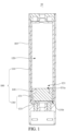
- an electronic vaporization device 10 includes a shell 101 and a vaporizer 100.
- the vaporizer 100 is accommodated in the shell 101, and the vaporizer 100 is configured to vaporize liquid.
- the shape of the shell is not particularly limited, and may be designed according to an actual case, for example, as a column shape, a bar shape, or a square shape.
- the shell 101 may be omitted.
- the electronic vaporization device 10 is an electronic cigarette, and the vaporizer 100 is configured to vaporize e-liquid.
- the electronic vaporization device 10 may also be other devices including the vaporizer 100.
- the electronic vaporization device 10 can vaporize liquid with relatively high viscosity.
- the vaporizer 100 includes a liquid storage container 110, a heating assembly 130, a seal member 140, a connection wiring, and a power supply.
- the liquid storage container 110 includes a liquid storage cavity 120 used for storing liquid (for example, e-liquid) to be vaporized.
- the liquid storage cavity 120 includes a liquid outlet 121.
- the liquid outlet 121 is used for inflow and/or outflow of the liquid to be vaporized.
- the heating assembly 130 is close to the liquid outlet 121.
- the heating assembly 130 is configured to absorb the liquid to be vaporized in the liquid storage cavity 120, and preheat and vaporize the liquid to be vaporized.
- the heating assembly 130 includes a preheating portion 131 and a vaporization portion 133 located on the preheating portion 131.
- the preheating portion 131 is made of a porous ceramic, and the preheating portion 131 is made of a positive temperature coefficient (PTC) thermosensitive material.
- PTC positive temperature coefficient
- the preheating portion 131 includes a liquid inlet surface 131a and a liquid outlet surface 131b opposite to the liquid inlet surface 131a.
- the liquid inlet surface 131a is close to the liquid outlet 121.
- the preheating portion 131 is configured to absorb the liquid to be vaporized in the liquid storage cavity 120, and preheat the liquid to be vaporized absorbed from the liquid storage cavity 120, to improve the flowability of the liquid to be vaporized in the preheating portion 131, so that the liquid to be vaporized in the liquid storage cavity 120 can reach the vaporization portion 133 more quickly to be vaporized into vapor for a user to inhale.
- the preheating portion 131 is made of the porous ceramic, and the porous ceramic enables the preheating portion 131 to absorb the liquid to be vaporized in the liquid storage cavity 120, to provide a liquid guide function.
- the preheating portion 131 is also made of the positive temperature coefficient thermosensitive material, that is, the preheating portion 131 is a thermistor.
- a resistance of the preheating portion 131 increases as the temperature increases, so that the preheating portion 131 can use electric energy to mainly preheat the liquid to be vaporized at an initial stage of energization, and can use the electric energy to mainly vaporize the liquid to be vaporized after the preheating ends. Therefore, the liquid to be vaporized is preheated, and it is avoided that only a small amount of the liquid to be vaporized is vaporized due to the poor flowability of the liquid to be vaporized.
- the preheating portion 131 preheats the liquid to be vaporized through a residual temperature, thereby further realizing energy saving.
- a Curie temperature of the preheating portion 131 does not exceed 200°C. Further, the Curie temperature of the preheating portion 131 is in a range from 100°C to 200°C. The Curie temperature is a temperature at which a PTC resistance begins to increase steeply. The Curie temperature of the preheating portion 131 is set as above, so that the liquid to be vaporized is rapidly preheated. In addition, the Curie temperature of the preheating portion 131 is set as above, which also controls distribution of the electric energy. By controlling the electric energy on the preheating portion 131, excessive electric energy on the preheating portion 131 being converted into heat energy and being wasted is avoided, and the utilization of the electric energy is improved.
- a positive temperature coefficient (PTC) intensity of the preheating portion 131 is greater than 1 ⁇ 10 2 . Further, the PTC intensity of the preheating portion 131 is in a range from 1 ⁇ 10 2 to 1 ⁇ 10 5 . Still further, the PTC intensity of the preheating portion 131 is in a range from 10 3 - to 10 5 .
- the PTC intensity of the preheating portion 131 is set as above, so that the resistance of the preheating portion 131 can be rapidly increased after a temperature range suitable for preheating is reached.
- the resistance of the preheating portion 131 is rapidly increased, so that the circuit in which the preheating portion 131 is located is turned into an open circuit more quickly, and then the current mainly flows to the circuit in which the vaporization portion 133 is located, to realize a rapid transition between the electric energy mainly being used for preheating and the electric energy mainly being used for vaporization.
- a resistivity of the preheating portion 131 under a normal temperature condition is in a range from 0.25 ⁇ /cm to 28 ⁇ /cm. Further, the resistivity of the preheating portion 131 under the normal temperature condition is in a range from 1 ⁇ /cm to 20 ⁇ /cm.
- the resistivity of the preheating portion 131 is set as above, so that the preheating portion 131 generates heat rapidly to heat the liquid to be vaporized in pores of the preheating portion 131.
- the preheating portion 131 is one selected from a BaTiO 3 -based PTC ceramic with a porous structure, a SrTiO 3 -based PTC ceramic with a porous structure, a PbTiO 3 -based PTC ceramic with a porous structure, or a V 2 O 3 -based PTC ceramic with a porous structure.
- the PTC ceramic is a semiconductor ceramic formed by sintering and is mainly composed of barium titanate (or strontium titanate and lead titanate), added with additives such as a small amount of rare earth elements (Y, Nb, Bi, and Sb), acceptor (Mn, Fe) elements, and glass (silicon oxide and aluminum oxide).
- the ceramic PTC has a small resistance below the Curie temperature, and the resistance thereof increases stepwise by a factor of 1,000 times to a million times above the Curie temperature.
- a donor is doped with ions such as La, Y, Nb, and Sb, and an acceptor is doped with 3d group metal elements such as Mn, Cu, and Fe. Through doping, the resistivity of the PTC ceramic under the normal temperature condition is reduced, and the PTC intensity is increased.
- the BaTiO 3 -based PTC ceramic with a porous structure is a porous ceramic made of barium titanate as basic material and doped with other polycrystalline ceramic materials.
- a PTC effect of BaTiO 3 is related to ferroelectricity of BaTiO 3 , and abrupt change of the resistivity of BaTiO 3 corresponds to the Curie temperature.
- a BaTiO 3 single crystal without a grain boundary does not have the PTC effect. Only a BaTiO 3 ceramic whose grains are fully semiconducted and whose grain boundary has proper insulation has the PTC effect.
- the grains are fully semiconducted by using donor doping, and the grain boundary and vicinity of the grain boundary are oxidized by sintering under oxygen atmosphere, to provide proper insulation. Slow cooling also makes the grain boundary fully oxidized, and the PTC effect is enhanced.
- the preheating portion 131 is doped with at least one of La, Y, Nb, or Sb.
- the rare earth elements are doped, so that impedance of the BaTiO 3 -based PTC ceramic under the normal temperature condition is lower, and the PTC intensity thereof is also increased.
- the preheating portion 131 is doped with La, and the doping amount of La is in a range from 0.1% to 1%. Doping La may cause the resistivity of the preheating portion 131 to reach 28 ⁇ /cm, and the PTC intensity thereof to reach 1 ⁇ 10 3.7 .
- the preheating portion 131 is not limited to be the above BaTiO 3 -based PTC ceramic with a porous structure, and may be other PTC ceramics with a porous structure.
- the preheating portion 131 is provided with an end electrode.
- the end electrode of the preheating portion 131 is electrically connected to the power supply.
- the shape of the preheating portion 131 is not particularly limited, for example, may be a bar shape, a cylinder shape, or a step shape.
- the vaporization portion 133 is located between the preheating portion 131 and the liquid outlet 121, and is configured to vaporize the liquid to be vaporized guided by the preheating portion 131. More specifically, the vaporization portion 133 is located on the liquid outlet surface 131b, and the vaporization portion 133 is configured to vaporize the liquid to be vaporized. In a static state, the circuit in which the preheating portion 131 is located and the circuit in which the vaporization portion 133 is located form a parallel circuit. In the illustrated implementation, the vaporization portion 133 is provided on the liquid outlet surface 131b in a contact manner.
- a ratio of a resistance of the vaporization portion 133 to a resistance of the preheating portion 131 is in a range from 1: 0.1 to 2.
- the ratio of the resistance of the vaporization portion 133 to the resistance of the preheating portion 131 is in a range from 1: 0.1 to 1.
- the ratio of the resistance of the vaporization portion 133 to the resistance of the preheating portion 131 is in a range from 1: 0.1 to 0.5.
- the electric energy may be mainly used for the preheating portion 131 to generate heat in the initial stage of energization, to preheat the liquid to be vaporized.
- the vaporization portion 133 is made of at least one selected from the groups consisting of a single metal, an alloy, an NTC ceramic, a carbon fiber, graphite, and combination thereof.
- the single metal may be selected from metals commonly used in the art for generating heat, for example, nickel, aluminum or the like.
- the alloy may be selected from alloys commonly used in the art for generating heat, for example, a nickel alloy, a silver alloy, an aluminum alloy or the like.
- the vaporization portion 133 is made of the NTC ceramic.
- a resistance of the NTC ceramic gradually decreases as the temperature increases.
- the vast majority of NTC ceramics are spinel-type oxides, mainly manganese-containing binary and manganese-containing ternary oxides.
- the manganese-containing binary oxides include MnO-CuO-O 2 -based oxides, MnO-CoO-O 2 -based oxides, MnO-NiO-O 2 -based oxides, etc.
- the manganese-containing ternary oxides include Mn-Co-Ni-based oxides, Mn-Cu-N-based oxides, Mn-Cu-Co-based oxide, etc.
- a MnO-CoO-O 2 -based oxide ceramic contains 23% to 60% (mass fraction) of manganese, and has main crystal phases of a cubic spinel MnCo 2 O 4 and a tetragonal spinel CoMn 2 O 4 , and a main conductive phase of MnCo 2 O 4 .
- the resistance of the vaporization portion 133 is relatively large, and enabling of the vaporization function is relatively delayed, so that the electric energy is mainly concentrated on the preheating portion 131.
- the preheating portion 131 As the preheating portion 131 generates heat continuously, the liquid to be vaporized is preheated, and, part of the heat is also transferred to the vaporization portion 133 so that the resistance of the vaporization portion 133 is reduced, thereby enabling the vaporization function of the vaporization portion 133. Therefore, when the vaporization portion 133 is made of the NTC ceramic, the heating assembly 130 can perform preheating and vaporization more quickly.
- the resistivity of the vaporization portion 133 under the normal temperature condition is in a range from 1 ⁇ 10 1 ⁇ /cm to 1 ⁇ 10 6 ⁇ /cm.
- a resistivity of the vaporization portion 133 under a condition of 60°C to 300°C is in a range from 1 ⁇ 10 -1 ⁇ /cm to 1 ⁇ 10 2 ⁇ /cm.
- the resistivity of the vaporization portion 133 under the normal temperature condition is in a range from 1 ⁇ 10 1 ⁇ /cm to 1 ⁇ 10 5 ⁇ /cm; and/or, the resistivity of the vaporization portion 133 under the condition of 60°C to 300°C is in a range from 1 ⁇ 10 -1 ⁇ /cm to 1 ⁇ 10 1.5 ⁇ /cm.
- the vaporization portion 133 is made of a normal temperature NTC thermistor ceramic. Further, the vaporization portion 133 is doped with at least one of La, Nd, or Ce. Doping at least one of La, Nd, or Ce reduces a thermosensitive constant and the resistivity under the normal temperature condition. In an embodiment, the vaporization portion 133 is doped with La. Further, the doping amount of La is 0.2%.
- the vaporization portion 133 is also provided with an end electrode, and the end electrode of the vaporization portion 133 is electrically connected to the power supply.
- the end electrode of the vaporization portion 133 also forms an ohmic contact with the preheating portion 131.
- the formation of ohmic contact between a metal and a semiconductor means that a pure resistor is located at the contact position, and the resistor is as small as possible, so that when the component operates, most of voltage is applied in an active region and not on a contact surface. Therefore, I-V characteristics of the ohmic contact exhibits a linear relationship. The larger the slope, the smaller the contact resistance of the ohmic contact. The magnitude of the contact resistance directly affects performance index of a device.
- the ohmic contact is widely applied to metal processing, and is achieved mainly by high doping or the introduction of a large number of recombination centers in a semiconductor surface layer.
- the shape of the vaporization portion 133 is not particularly limited, and may adopt a common shape in the art.
- the shape may be a sheet shape, a grid shape, a bar shape or the like.
- the seal member 140 is located between the heating assembly 130 and the liquid storage container 110, and is configured to seal a gap between the heating assembly 130 and the liquid storage container 110, so that the liquid to be vaporized can reach the vaporization portion 133 to be vaporized without flowing out from a liquid guide portion and/or a side wall of the preheating portion 131.
- connection wiring is configured to electrically connect the preheating portion 131 and the vaporization portion 133 to the power supply.
- the preheating portion 131 and the vaporization portion 133 are connected in parallel by the connection wiring, and then connected to the power supply. It may be understood that in some other embodiments, the connection wiring may be omitted.
- the connection wiring When the connection wiring is omitted, the vaporizer 100 during use causes, through the connection wiring provided outside, the power supply to supply power to the preheating portion 131 and the vaporization portion 133 that are connected in parallel.
- the power supply is configured to supply power to the vaporizer 100. Further, the power supply is configured to supply power to the heating assembly 130. In this implementation, the power supply is accommodated in the shell 101. Certainly, in other implementations, the power supply may not be accommodated in the shell 101. In this case, the power supply may be separately accommodated in a housing, or the power supply may be accommodated in a space formed by extending the liquid storage container 110 in an extending direction of the liquid storage container. It may be understood that in some other implementations, the power supply may be omitted. When the power supply is omitted, the vaporizer 100 supplies power to the heating assembly 130 through an external power supply.
- the electronic vaporizer 10 has the following advantages.
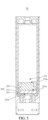
- a structure of the electronic vaporization device 20 is basically the same as that of the electronic vaporization device 10, except a difference lying in that a heating assembly 230 of the electronic vaporization device 20 further includes a liquid guide portion 235.
- the liquid guide portion 235 is located on a side of a preheating portion 231 away from a vaporization portion 233, and the liquid guide portion 235 is made of a porous ceramic. Specifically, the liquid guide portion 235 is located between a liquid outlet 221 and a preheating portion 231, so that liquid to be vaporized reaches the preheating portion 231 through the liquid guide portion 235 after flowing out from the liquid outlet 221.
- the liquid guide portion 235 is located on a liquid inlet surface 231a of the preheating portion 231.
- the liquid guide portion 235 includes a liquid absorbing surface 235a.
- the liquid absorbing surface 235a is far away from the liquid inlet surface 231a.
- the electronic vaporization device 20 has a structure similar to that of the electronic vaporization device 10, and therefore, also has advantages similar to those of the electronic vaporization device 10.
- the electronic vaporization device 20 is provided with the liquid guide portion 235, so that heat generated by the preheating portion 231 mainly heats the liquid to be vaporized in pores of the preheating portion 231, thereby reducing dissipation of the heat generated by the preheating portion 231 and improving preheating efficiency of the preheating portion 231.
- the vaporizer since the vaporizer has a certain requirement on a thickness of an element that provides a liquid guide function, and both the liquid guide portion 235 and the preheating portion 231 have the liquid guide function, the provision of the liquid guide portion 235 is also cost-saving.
Landscapes
- Physics & Mathematics (AREA)
- Electromagnetism (AREA)
- Chemical & Material Sciences (AREA)
- Engineering & Computer Science (AREA)
- Ceramic Engineering (AREA)
- Resistance Heating (AREA)
Claims (14)
- Heizanordnung (130, 230), umfassend:einen Vorwärmabschnitt (131); undeinen Verdampfungsabschnitt (133, 233),wobei ein Stromkreis, in dem sich der Vorwärmabschnitt (131, 231) befindet, parallel mit einem Stromkreis verschaltet ist, in dem sich der Verdampfungsabschnitt (133, 233) befindet;dadurch gekennzeichnet, dass der Vorwärmabschnitt (131) aus einer porösen Keramik hergestellt ist, der Vorwärmabschnitt (131) aus einem wärmeempfindlichen Material mit positivem Temperaturkoeffizienten hergestellt ist und sich der Verdampfungsabschnitt (133, 233) auf dem Vorwärmabschnitt (131, 231) befindet.
- Heizanordnung (130, 230) nach Anspruch 1, wobei unter einer normalen Temperaturbedingung das Verhältnis des Widerstands des Verdampfungsabschnitts (133) zum Widerstand des Vorwärmabschnitts (131) im Bereich von 1:0,1 bis 2 liegt.
- Heizanordnung (130, 230) nach Anspruch 1, wobei die Curie-Temperatur des Vorwärmabschnitts (131) 200 °C nicht überschreitet; und/oder der spezifische Widerstand des Vorwärmabschnitts (131) unter einer normalen Temperaturbedingung im Bereich von 0,25 Ω/cm bis 28 Ω/cm liegt; und/oder die PTC-Intensität des Vorwärmabschnitts (131) im Bereich von 1×10² bis 1×10⁵ liegt.
- Heizanordnung (130, 230) nach Anspruch 1, wobei die Curie-Temperatur des Vorwärmabschnitts (131) im Bereich von 100 °C bis 200 °C liegt; und/oder der spezifische Widerstand des Vorwärmabschnitts (131) unter einer normalen Temperaturbedingung im Bereich von 1 Ω/cm bis 20 Ω/cm liegt; und/oder die PTC-Intensität des Vorwärmabschnitts (131) im Bereich von 1 × 10³ bis 1 × 10⁵ liegt.
- Heizanordnung (130, 230) nach Anspruch 1, wobei der Vorwärmabschnitt (131) einer ist, der aus einer PTC-Keramik auf BaTiO3 -Basis mit einer porösen Struktur, einer PTC-Keramik auf SrTiOs -Basis mit einer porösen Struktur, einer PTC-Keramik auf PbTiOs -Basis mit einer porösen Struktur oder einer PTC-Keramik auf V2O3 -Basis mit einer porösen Struktur ausgewählt ist.
- Heizanordnung (130, 230) nach Anspruch 4, wobei der Vorwärmabschnitt (131) mit mindestens einem von La, Y, Nb oder Sb dotiert ist.
- Heizanordnung (130, 230) nach Anspruch 1, wobei der Vorwärmabschnitt (131) eine Flüssigkeitseinlassfläche (131a) und eine Flüssigkeitsauslassfläche (131b) gegenüber der Flüssigkeitseinlassfläche (131a) umfasst; und sich der Verdampfungsabschnitt (133) auf der Flüssigkeitsauslassfläche (131b) befindet.
- Heizanordnung (130, 230) nach einem der Ansprüche 1 bis 7, wobei der Verdampfungsabschnitt (133) aus mindestens einem hergestellt ist, das aus den Gruppen ausgewählt ist, die aus einem einzelnen Metall, einer Legierung, einer NTC-Keramik, einer Kohlenstofffaser, Graphit und einer Kombination davon bestehen.
- Heizanordnung (130, 230) nach Anspruch 8, wobei der Verdampfungsabschnitt (133) aus der NTC-Keramik hergestellt ist;
der spezifische Widerstand des Verdampfungsabschnitts (133) unter einer normalen Temperaturbedingung im Bereich von 1 × 101 Ω/cm bis 1 × 10⁶ Ω/cm liegt; und/oder der spezifische Widerstand des Verdampfungsabschnitts (133) unter der Bedingung von 60 °C bis 300 °C im Bereich von 1 × 10⁻¹ Ω/cm bis 1 × 10² Ω/cm liegt. - Heizanordnung (130, 230) nach Anspruch 9, wobei der Verdampfungsabschnitt (133) mit mindestens einem von La, Nd oder Ce dotiert ist.
- Heizanordnung (230) nach einem der Ansprüche 1 bis 7, ferner umfassend einen Flüssigkeitsführungsabschnitt (235), wobei sich der Flüssigkeitsführungsabschnitt (235) auf einer Seite des Vorwärmabschnitts (231) entfernt vom Verdampfungsabschnitt (233) befindet und der Flüssigkeitsführungsabschnitt (235) aus einer porösen Keramik hergestellt ist.
- Verdampfer (100), umfassend:einen Flüssigkeitsspeicherbehälter (110), umfassend einen Flüssigkeitsspeicherhohlraum (120), der zum Speichern einer zu verdampfenden Flüssigkeit konfiguriert ist, wobei der Flüssigkeitsspeicherhohlraum (120) mit einem Flüssigkeitsauslass (121) versehen ist; undeine Heizanordnung, die zum Verdampfen der zu verdampfenden Flüssigkeit konfiguriert ist, wobei die Heizanordnung die Heizanordnung (130, 230) nach einem der Ansprüche 1 bis 11 ist und sich der Vorwärmabschnitt (131) nahe dem Flüssigkeitsauslass (121) befindet.
- Verdampfer (100) nach Anspruch 12, wobei sich der Vorwärmabschnitt (131) zwischen dem Verdampfungsabschnitt (133) und dem Flüssigkeitsauslass (121) befindet und der Verdampfungsabschnitt (133) zum Verdampfen der zu verdampfenden Flüssigkeit konfiguriert ist, die vom Vorwärmabschnitt (131) geführt wird.
- Elektronische Verdampfungsvorrichtung (10, 20), umfassend:
einen Verdampfer (100), wobei der Verdampfer (100) umfasst:einen Flüssigkeitsspeicherbehälter (110), umfassend einen Flüssigkeitsspeicherhohlraum (120), der zum Speichern einer zu verdampfenden Flüssigkeit konfiguriert ist, wobei der Flüssigkeitsspeicherhohlraum (120) mit einem Flüssigkeitsauslass (121) versehen ist; undeine Heizanordnung, die zum Verdampfen der zu verdampfenden Flüssigkeit konfiguriert ist, wobei die Heizanordnung die Heizanordnung (130, 230) nach einem der Ansprüche 1 bis 11 ist und sich der Vorwärmabschnitt (131) nahe dem Flüssigkeitsauslass (121) befindet; undeine Stromversorgung, die zum Versorgen des Verdampfers (100) mit Strom konfiguriert ist.
Applications Claiming Priority (1)
| Application Number | Priority Date | Filing Date | Title |
|---|---|---|---|
| PCT/CN2020/086971 WO2021217292A1 (zh) | 2020-04-26 | 2020-04-26 | 发热组件、雾化器和电子雾化装置 |
Publications (3)
| Publication Number | Publication Date |
|---|---|
| EP4136992A1 EP4136992A1 (de) | 2023-02-22 |
| EP4136992A4 EP4136992A4 (de) | 2024-01-10 |
| EP4136992B1 true EP4136992B1 (de) | 2024-11-13 |
Family
ID=78373211
Family Applications (1)
| Application Number | Title | Priority Date | Filing Date |
|---|---|---|---|
| EP20933090.1A Active EP4136992B1 (de) | 2020-04-26 | 2020-04-26 | Heizanordnung, zerstäuber und elektronische zerstäubungsvorrichtung |
Country Status (3)
| Country | Link |
|---|---|
| US (1) | US20230057645A1 (de) |
| EP (1) | EP4136992B1 (de) |
| WO (1) | WO2021217292A1 (de) |
Families Citing this family (5)
| Publication number | Priority date | Publication date | Assignee | Title |
|---|---|---|---|---|
| CN217509914U (zh) * | 2022-04-06 | 2022-09-30 | 海南摩尔兄弟科技有限公司 | 雾化芯及电子雾化装置 |
| WO2023216263A1 (zh) * | 2022-05-13 | 2023-11-16 | 深圳麦克韦尔科技有限公司 | 发热体、雾化组件及电子雾化装置 |
| CN117223908A (zh) * | 2022-06-06 | 2023-12-15 | 比亚迪精密制造有限公司 | 一种雾化芯和电子雾化装置 |
| CN116210978B (zh) * | 2023-02-28 | 2025-08-01 | 爱奇迹(深圳)创新科技有限公司 | 雾化芯及其制备方法、雾化装置 |
| EP4489519A1 (de) * | 2023-07-05 | 2025-01-08 | JT International SA | Dampferzeugungseinheit |
Family Cites Families (9)
| Publication number | Priority date | Publication date | Assignee | Title |
|---|---|---|---|---|
| AT507187B1 (de) * | 2008-10-23 | 2010-03-15 | Helmut Dr Buchberger | Inhalator |
| GB201701102D0 (en) * | 2017-01-23 | 2017-03-08 | Nicoventures Holdings Ltd | Electronic vapour provision system |
| CN108926039A (zh) * | 2017-05-23 | 2018-12-04 | 深圳市康尔科技有限公司 | 一种容量可调储液装置以及具有容量可调储液装置的电子烟 |
| JP2020058237A (ja) * | 2018-10-04 | 2020-04-16 | 日本たばこ産業株式会社 | 吸引成分生成装置、制御回路、吸引成分生成装置の制御方法および制御プログラム |
| CN109288140B (zh) * | 2018-12-06 | 2021-08-27 | 广东国研新材料有限公司 | 一种电子烟用多孔陶瓷发热体及其制备方法 |
| CN110269280B (zh) * | 2019-06-21 | 2024-01-02 | 东莞市阿尔法电子科技有限公司 | 电子烟及烟弹识别方法 |
| CN110447966B (zh) * | 2019-08-12 | 2025-02-18 | 深圳麦克韦尔科技有限公司 | 发热体、雾化器和电子雾化装置 |
| CN110584212B (zh) * | 2019-09-16 | 2024-10-15 | 深圳麦克韦尔科技有限公司 | 雾化芯、雾化器及电子雾化装置 |
| CN110786552B (zh) * | 2019-11-21 | 2020-10-23 | 深圳市吉迩科技有限公司 | 一种雾化装置、雾化方法及电子烟 |
-
2020
- 2020-04-26 EP EP20933090.1A patent/EP4136992B1/de active Active
- 2020-04-26 WO PCT/CN2020/086971 patent/WO2021217292A1/zh not_active Ceased
-
2022
- 2022-10-12 US US18/046,086 patent/US20230057645A1/en active Pending
Also Published As
| Publication number | Publication date |
|---|---|
| WO2021217292A1 (zh) | 2021-11-04 |
| EP4136992A1 (de) | 2023-02-22 |
| US20230057645A1 (en) | 2023-02-23 |
| EP4136992A4 (de) | 2024-01-10 |
Similar Documents
| Publication | Publication Date | Title |
|---|---|---|
| EP4136992B1 (de) | Heizanordnung, zerstäuber und elektronische zerstäubungsvorrichtung | |
| CN102403077B (zh) | 陶瓷层叠ptc热敏电阻 | |
| CN212814273U (zh) | 发热组件、雾化器和电子雾化装置 | |
| CN113053604B (zh) | Ntc陶瓷、用于接通电流限制的电子器件以及用于制造电子器件的方法 | |
| US20090015367A1 (en) | Nonlinear resistor ceramic composition, electronic component, and multilayer chip varistor | |
| CN113545529B (zh) | 发热组件、雾化器和电子雾化装置 | |
| JPH0719645B2 (ja) | 自己温度制御型発熱装置 | |
| JPS59153027A (ja) | グロ−プラグ | |
| KR102335014B1 (ko) | 고체 산화물 연료전지용 전극 재료 및 그의 제조방법 | |
| CN100405509C (zh) | 层叠型正特性热敏电阻 | |
| JPH09208310A (ja) | 半導体磁器組成物とそれを用いた半導体磁器素子 | |
| JP2000156328A (ja) | キャパシタまたは電池に使用される集電体の製造方法 | |
| CN101268527B (zh) | 层叠型正特性热敏电阻 | |
| JP5626204B2 (ja) | 半導体磁器組成物、発熱体及び発熱モジュール | |
| JP2008159965A (ja) | 電子部品及びその製造方法 | |
| JP3087012B2 (ja) | セラミックヒーター | |
| JP5263668B2 (ja) | 半導体磁器組成物 | |
| JP2012046372A (ja) | Ptc素子および発熱モジュール | |
| US3148271A (en) | Circuit arrangement for automatically stabilizing the temperature of an electrical heating appliance | |
| WO2011007664A1 (ja) | セラミックヒーター | |
| JP4780306B2 (ja) | 積層型サーミスタ及びその製造方法 | |
| JP2012209292A (ja) | 正特性サーミスタ | |
| US20080266755A1 (en) | NbO Capacitors With Improved Performance and Higher Working Voltages | |
| CN219370808U (zh) | 支撑结构 | |
| JP3425097B2 (ja) | 抵抗素子 |
Legal Events
| Date | Code | Title | Description |
|---|---|---|---|
| STAA | Information on the status of an ep patent application or granted ep patent |
Free format text: STATUS: THE INTERNATIONAL PUBLICATION HAS BEEN MADE |
|
| PUAI | Public reference made under article 153(3) epc to a published international application that has entered the european phase |
Free format text: ORIGINAL CODE: 0009012 |
|
| STAA | Information on the status of an ep patent application or granted ep patent |
Free format text: STATUS: REQUEST FOR EXAMINATION WAS MADE |
|
| 17P | Request for examination filed |
Effective date: 20221115 |
|
| AK | Designated contracting states |
Kind code of ref document: A1 Designated state(s): AL AT BE BG CH CY CZ DE DK EE ES FI FR GB GR HR HU IE IS IT LI LT LU LV MC MK MT NL NO PL PT RO RS SE SI SK SM TR |
|
| DAV | Request for validation of the european patent (deleted) | ||
| DAX | Request for extension of the european patent (deleted) | ||
| REG | Reference to a national code |
Ref country code: DE Ref legal event code: R079 Free format text: PREVIOUS MAIN CLASS: A24F0047000000 Ipc: A24F0040460000 Ref document number: 602020041500 Country of ref document: DE |
|
| A4 | Supplementary search report drawn up and despatched |
Effective date: 20231213 |
|
| RIC1 | Information provided on ipc code assigned before grant |
Ipc: H05B 3/14 20060101ALI20231207BHEP Ipc: A24F 40/46 20200101AFI20231207BHEP |
|
| GRAP | Despatch of communication of intention to grant a patent |
Free format text: ORIGINAL CODE: EPIDOSNIGR1 |
|
| STAA | Information on the status of an ep patent application or granted ep patent |
Free format text: STATUS: GRANT OF PATENT IS INTENDED |
|
| RIC1 | Information provided on ipc code assigned before grant |
Ipc: H05B 3/14 20060101ALI20240717BHEP Ipc: A24F 40/46 20200101AFI20240717BHEP |
|
| INTG | Intention to grant announced |
Effective date: 20240726 |
|
| GRAS | Grant fee paid |
Free format text: ORIGINAL CODE: EPIDOSNIGR3 |
|
| P01 | Opt-out of the competence of the unified patent court (upc) registered |
Free format text: CASE NUMBER: APP_50245/2024 Effective date: 20240904 |
|
| GRAA | (expected) grant |
Free format text: ORIGINAL CODE: 0009210 |
|
| STAA | Information on the status of an ep patent application or granted ep patent |
Free format text: STATUS: THE PATENT HAS BEEN GRANTED |
|
| RAP3 | Party data changed (applicant data changed or rights of an application transferred) |
Owner name: SHENZHEN SMOORE TECHNOLOGY LIMITED |
|
| AK | Designated contracting states |
Kind code of ref document: B1 Designated state(s): AL AT BE BG CH CY CZ DE DK EE ES FI FR GB GR HR HU IE IS IT LI LT LU LV MC MK MT NL NO PL PT RO RS SE SI SK SM TR |
|
| REG | Reference to a national code |
Ref country code: GB Ref legal event code: FG4D |
|
| REG | Reference to a national code |
Ref country code: CH Ref legal event code: EP |
|
| REG | Reference to a national code |
Ref country code: IE Ref legal event code: FG4D |
|
| REG | Reference to a national code |
Ref country code: DE Ref legal event code: R096 Ref document number: 602020041500 Country of ref document: DE |
|
| REG | Reference to a national code |
Ref country code: LT Ref legal event code: MG9D |
|
| REG | Reference to a national code |
Ref country code: NL Ref legal event code: MP Effective date: 20241113 |
|
| PG25 | Lapsed in a contracting state [announced via postgrant information from national office to epo] |
Ref country code: HR Free format text: LAPSE BECAUSE OF FAILURE TO SUBMIT A TRANSLATION OF THE DESCRIPTION OR TO PAY THE FEE WITHIN THE PRESCRIBED TIME-LIMIT Effective date: 20241113 Ref country code: IS Free format text: LAPSE BECAUSE OF FAILURE TO SUBMIT A TRANSLATION OF THE DESCRIPTION OR TO PAY THE FEE WITHIN THE PRESCRIBED TIME-LIMIT Effective date: 20250313 Ref country code: PT Free format text: LAPSE BECAUSE OF FAILURE TO SUBMIT A TRANSLATION OF THE DESCRIPTION OR TO PAY THE FEE WITHIN THE PRESCRIBED TIME-LIMIT Effective date: 20250313 |
|
| PG25 | Lapsed in a contracting state [announced via postgrant information from national office to epo] |
Ref country code: FI Free format text: LAPSE BECAUSE OF FAILURE TO SUBMIT A TRANSLATION OF THE DESCRIPTION OR TO PAY THE FEE WITHIN THE PRESCRIBED TIME-LIMIT Effective date: 20241113 Ref country code: NL Free format text: LAPSE BECAUSE OF FAILURE TO SUBMIT A TRANSLATION OF THE DESCRIPTION OR TO PAY THE FEE WITHIN THE PRESCRIBED TIME-LIMIT Effective date: 20241113 |
|
| REG | Reference to a national code |
Ref country code: AT Ref legal event code: MK05 Ref document number: 1740921 Country of ref document: AT Kind code of ref document: T Effective date: 20241113 |
|
| PG25 | Lapsed in a contracting state [announced via postgrant information from national office to epo] |
Ref country code: BG Free format text: LAPSE BECAUSE OF FAILURE TO SUBMIT A TRANSLATION OF THE DESCRIPTION OR TO PAY THE FEE WITHIN THE PRESCRIBED TIME-LIMIT Effective date: 20241113 |
|
| PG25 | Lapsed in a contracting state [announced via postgrant information from national office to epo] |
Ref country code: ES Free format text: LAPSE BECAUSE OF FAILURE TO SUBMIT A TRANSLATION OF THE DESCRIPTION OR TO PAY THE FEE WITHIN THE PRESCRIBED TIME-LIMIT Effective date: 20241113 |
|
| PG25 | Lapsed in a contracting state [announced via postgrant information from national office to epo] |
Ref country code: NO Free format text: LAPSE BECAUSE OF FAILURE TO SUBMIT A TRANSLATION OF THE DESCRIPTION OR TO PAY THE FEE WITHIN THE PRESCRIBED TIME-LIMIT Effective date: 20250213 |
|
| PG25 | Lapsed in a contracting state [announced via postgrant information from national office to epo] |
Ref country code: GR Free format text: LAPSE BECAUSE OF FAILURE TO SUBMIT A TRANSLATION OF THE DESCRIPTION OR TO PAY THE FEE WITHIN THE PRESCRIBED TIME-LIMIT Effective date: 20250214 Ref country code: LV Free format text: LAPSE BECAUSE OF FAILURE TO SUBMIT A TRANSLATION OF THE DESCRIPTION OR TO PAY THE FEE WITHIN THE PRESCRIBED TIME-LIMIT Effective date: 20241113 Ref country code: AT Free format text: LAPSE BECAUSE OF FAILURE TO SUBMIT A TRANSLATION OF THE DESCRIPTION OR TO PAY THE FEE WITHIN THE PRESCRIBED TIME-LIMIT Effective date: 20241113 |
|
| PG25 | Lapsed in a contracting state [announced via postgrant information from national office to epo] |
Ref country code: PL Free format text: LAPSE BECAUSE OF FAILURE TO SUBMIT A TRANSLATION OF THE DESCRIPTION OR TO PAY THE FEE WITHIN THE PRESCRIBED TIME-LIMIT Effective date: 20241113 |
|
| PG25 | Lapsed in a contracting state [announced via postgrant information from national office to epo] |
Ref country code: RS Free format text: LAPSE BECAUSE OF FAILURE TO SUBMIT A TRANSLATION OF THE DESCRIPTION OR TO PAY THE FEE WITHIN THE PRESCRIBED TIME-LIMIT Effective date: 20250213 |
|
| RAP4 | Party data changed (patent owner data changed or rights of a patent transferred) |
Owner name: SHENZHEN SMOORE TECHNOLOGY LIMITED |
|
| PG25 | Lapsed in a contracting state [announced via postgrant information from national office to epo] |
Ref country code: SM Free format text: LAPSE BECAUSE OF FAILURE TO SUBMIT A TRANSLATION OF THE DESCRIPTION OR TO PAY THE FEE WITHIN THE PRESCRIBED TIME-LIMIT Effective date: 20241113 |
|
| PGFP | Annual fee paid to national office [announced via postgrant information from national office to epo] |
Ref country code: DE Payment date: 20250411 Year of fee payment: 6 |
|
| PG25 | Lapsed in a contracting state [announced via postgrant information from national office to epo] |
Ref country code: DK Free format text: LAPSE BECAUSE OF FAILURE TO SUBMIT A TRANSLATION OF THE DESCRIPTION OR TO PAY THE FEE WITHIN THE PRESCRIBED TIME-LIMIT Effective date: 20241113 |
|
| PGFP | Annual fee paid to national office [announced via postgrant information from national office to epo] |
Ref country code: GB Payment date: 20250417 Year of fee payment: 6 |
|
| PG25 | Lapsed in a contracting state [announced via postgrant information from national office to epo] |
Ref country code: EE Free format text: LAPSE BECAUSE OF FAILURE TO SUBMIT A TRANSLATION OF THE DESCRIPTION OR TO PAY THE FEE WITHIN THE PRESCRIBED TIME-LIMIT Effective date: 20241113 |
|
| PGFP | Annual fee paid to national office [announced via postgrant information from national office to epo] |
Ref country code: FR Payment date: 20250430 Year of fee payment: 6 |
|
| PG25 | Lapsed in a contracting state [announced via postgrant information from national office to epo] |
Ref country code: RO Free format text: LAPSE BECAUSE OF FAILURE TO SUBMIT A TRANSLATION OF THE DESCRIPTION OR TO PAY THE FEE WITHIN THE PRESCRIBED TIME-LIMIT Effective date: 20241113 |
|
| PG25 | Lapsed in a contracting state [announced via postgrant information from national office to epo] |
Ref country code: SK Free format text: LAPSE BECAUSE OF FAILURE TO SUBMIT A TRANSLATION OF THE DESCRIPTION OR TO PAY THE FEE WITHIN THE PRESCRIBED TIME-LIMIT Effective date: 20241113 |
|
| PG25 | Lapsed in a contracting state [announced via postgrant information from national office to epo] |
Ref country code: CZ Free format text: LAPSE BECAUSE OF FAILURE TO SUBMIT A TRANSLATION OF THE DESCRIPTION OR TO PAY THE FEE WITHIN THE PRESCRIBED TIME-LIMIT Effective date: 20241113 |
|
| PG25 | Lapsed in a contracting state [announced via postgrant information from national office to epo] |
Ref country code: IT Free format text: LAPSE BECAUSE OF FAILURE TO SUBMIT A TRANSLATION OF THE DESCRIPTION OR TO PAY THE FEE WITHIN THE PRESCRIBED TIME-LIMIT Effective date: 20241113 |
|
| REG | Reference to a national code |
Ref country code: DE Ref legal event code: R097 Ref document number: 602020041500 Country of ref document: DE |
|
| PG25 | Lapsed in a contracting state [announced via postgrant information from national office to epo] |
Ref country code: SE Free format text: LAPSE BECAUSE OF FAILURE TO SUBMIT A TRANSLATION OF THE DESCRIPTION OR TO PAY THE FEE WITHIN THE PRESCRIBED TIME-LIMIT Effective date: 20241113 |
|
| PLBE | No opposition filed within time limit |
Free format text: ORIGINAL CODE: 0009261 |
|
| STAA | Information on the status of an ep patent application or granted ep patent |
Free format text: STATUS: NO OPPOSITION FILED WITHIN TIME LIMIT |
|
| 26N | No opposition filed |
Effective date: 20250814 |
|
| REG | Reference to a national code |
Ref country code: CH Ref legal event code: H13 Free format text: ST27 STATUS EVENT CODE: U-0-0-H10-H13 (AS PROVIDED BY THE NATIONAL OFFICE) Effective date: 20251125 |
|
| PG25 | Lapsed in a contracting state [announced via postgrant information from national office to epo] |
Ref country code: LU Free format text: LAPSE BECAUSE OF NON-PAYMENT OF DUE FEES Effective date: 20250426 |
|
| PG25 | Lapsed in a contracting state [announced via postgrant information from national office to epo] |
Ref country code: MC Free format text: LAPSE BECAUSE OF FAILURE TO SUBMIT A TRANSLATION OF THE DESCRIPTION OR TO PAY THE FEE WITHIN THE PRESCRIBED TIME-LIMIT Effective date: 20241113 |
|
| REG | Reference to a national code |
Ref country code: BE Ref legal event code: MM Effective date: 20250430 |
|
| PG25 | Lapsed in a contracting state [announced via postgrant information from national office to epo] |
Ref country code: BE Free format text: LAPSE BECAUSE OF NON-PAYMENT OF DUE FEES Effective date: 20250430 |
|
| PG25 | Lapsed in a contracting state [announced via postgrant information from national office to epo] |
Ref country code: CH Free format text: LAPSE BECAUSE OF NON-PAYMENT OF DUE FEES Effective date: 20250430 |