EP4134645B1 - Temperatursensormodul und temperaturmesssystem damit - Google Patents
Temperatursensormodul und temperaturmesssystem damit Download PDFInfo
- Publication number
- EP4134645B1 EP4134645B1 EP22177418.5A EP22177418A EP4134645B1 EP 4134645 B1 EP4134645 B1 EP 4134645B1 EP 22177418 A EP22177418 A EP 22177418A EP 4134645 B1 EP4134645 B1 EP 4134645B1
- Authority
- EP
- European Patent Office
- Prior art keywords
- heat
- extension
- temperature
- region
- patterned portion
- Prior art date
- Legal status (The legal status is an assumption and is not a legal conclusion. Google has not performed a legal analysis and makes no representation as to the accuracy of the status listed.)
- Active
Links
Images




Classifications
-
- G—PHYSICS
- G01—MEASURING; TESTING
- G01K—MEASURING TEMPERATURE; MEASURING QUANTITY OF HEAT; THERMALLY-SENSITIVE ELEMENTS NOT OTHERWISE PROVIDED FOR
- G01K7/00—Measuring temperature based on the use of electric or magnetic elements directly sensitive to heat ; Power supply therefor, e.g. using thermoelectric elements
- G01K7/02—Measuring temperature based on the use of electric or magnetic elements directly sensitive to heat ; Power supply therefor, e.g. using thermoelectric elements using thermoelectric elements, e.g. thermocouples
- G01K7/04—Measuring temperature based on the use of electric or magnetic elements directly sensitive to heat ; Power supply therefor, e.g. using thermoelectric elements using thermoelectric elements, e.g. thermocouples the object to be measured not forming one of the thermoelectric materials
-
- G—PHYSICS
- G01—MEASURING; TESTING
- G01K—MEASURING TEMPERATURE; MEASURING QUANTITY OF HEAT; THERMALLY-SENSITIVE ELEMENTS NOT OTHERWISE PROVIDED FOR
- G01K1/00—Details of thermometers not specially adapted for particular types of thermometer
- G01K1/16—Special arrangements for conducting heat from the object to the sensitive element
-
- G—PHYSICS
- G01—MEASURING; TESTING
- G01K—MEASURING TEMPERATURE; MEASURING QUANTITY OF HEAT; THERMALLY-SENSITIVE ELEMENTS NOT OTHERWISE PROVIDED FOR
- G01K7/00—Measuring temperature based on the use of electric or magnetic elements directly sensitive to heat ; Power supply therefor, e.g. using thermoelectric elements
- G01K7/02—Measuring temperature based on the use of electric or magnetic elements directly sensitive to heat ; Power supply therefor, e.g. using thermoelectric elements using thermoelectric elements, e.g. thermocouples
Definitions
- the present invention generally relates to a temperature sensor module and a temperature measurement system including the same.
- the present invention relates to a temperature sensor module which can be installed in a compact manner in a high-temperature facility not allowing temperature measurement due to inaccessibility to an operator or an external environment thereof, and can quickly and accurately measure the temperature of the high-temperature facility, and a temperature measurement system including the same.
- Temperature control of a battery in an electric vehicle is very important since the temperature of the battery is directly related to an operating condition and safety of the vehicle. Further, it is very important to control the temperature of a fire-resistant structure used in a high temperature environment, such as a melting furnace that produces molten iron by melting raw materials, such as iron ore and the like, since the operating temperature of the fire-resistant structure is directly related to quality of products.
- a fire-resistant structure used in a high temperature environment such as a melting furnace that produces molten iron by melting raw materials, such as iron ore and the like
- a temperature sensor is used to provide real-time measurement of the temperature of a sensing target exposed to a high-temperature environment, such as a battery or a fire-resistant structure, in order to maintain an optimal operating environment for the sensing target or to reduce the risk of accidents, such as fire.
- thermosensor In a sensing target exposed to a high-temperature environment, such as a melting furnace, due to inaccessibility to an operator or a high-temperature environment.
- conventional temperature sensors are mostly point temperature sensors that measure the temperature of a specific point on a sensing target, and thus have difficulty in accurately measuring the temperature of a large-area sensing target such as a melting furnace.
- this method has a problem in that it is structurally difficult to install a large number of temperature sensors on the sensing target, and in that it is also structurally difficult to collect sensing results from such a large number of temperature sensors and to process the collected sensing results.
- Korean Patent Laid-open Publication No. 2006-0063405 ( Issue Date: 2006.06.12 ) discloses a probe capable of measuring temperature inside of blast furnace.
- US 8 801 283 B2 discloses an electric circuit body for measuring a temperature of a battery of an electric vehicle.
- DE 10 2010 030769 A1 discloses a sensor for determining a signal proportional to the temperature of a motor vehicle interior.
- the invention is defined by claim 1.
- Embodiments of the present invention are conceived to solve such problems in the art and it is an object of the present invention to provide a temperature sensor module which can be installed in a compact manner in a high-temperature facility, which does not allow temperature measurement due to inaccessibility to an operator or an external environment thereof, and can quickly and accurately measure the temperature of the high-temperature facility, and a temperature measurement system including the same.
- a temperature sensor module includes: a sensor unit having a sensing end for measurement of a temperature of a heat source; a heat conduction panel formed of a thermally conductive material and having a temperature measurement region connected to the sensing end and exposed to the heat source such that heat transferred from the heat source to the temperature measurement region is transferred to the sensing end along a surface of the temperature measurement region; and a heat insulation panel disposed opposite the heat source with respect to the heat conduction panel to prevent heat generated from the heat source or heat transferred to the heat conduction panel from being discharged to an outside of the temperature sensor module or to prevent external heat from being transferred to the heat conduction panel.
- the heat conduction panel includes a patterned portion forming at least a portion of the temperature measurement region.
- the patterned portion includes: a first patterned portion having a first inner region connected to the sensing end, a first outer region separated a first linear distance from the first inner region, and a first extension connecting the first inner region to the first outer region; and a second patterned portion having a second inner region connected to the sensing end, a second outer region separated from the second inner region by a second linear distance longer than the first linear distance, and a second extension connecting the second inner region to the second outer region.
- first extension and the second extension may have the same length.
- first extension and the second extension may have different lengths, wherein the first extension may have a first heat conductivity and the second extension may have a second heat conductivity greater than the first heat conductivity.
- first extension and the second extension may have different lengths, wherein the first extension may have a first area and the second extension may have a second area larger than the first area.
- the heat conduction panel may further include: a heat collecting portion disposed in the first outer region or the second outer region to collect heat transferred from the heat source, wherein the heat collecting portion may be formed of a material having greater heat conductivity than the first patterned portion and the second patterned portion.
- the sensor unit may include: a thermocouple having the sensing end as a hot junction; and a processor connected to a cold junction of the thermocouple and performing temperature calculation from thermoelectromotive force depending on a temperature of the thermocouple.
- a temperature measurement system including: the temperature sensor module set forth above; and a management module receiving temperature information measured and processed by the temperature sensor module and displaying a temperature of the temperature measurement region.
- the temperature sensor module With the heat conduction panel connected to the sensing end and extending parallel to the surface of the temperature measurement region, the temperature sensor module according to the present invention can quickly and accurately measure and process information about the temperature of a heat source or a structure filled with the heat source, thereby allowing stable and systematic management of the heat source or the structure filled with the heat source based on the acquired temperature information.
- FIG. 1 is a schematic perspective view of a temperature sensor module according to one embodiment of the present invention
- FIG. 2 is a plan view of a temperature measurement region of a heat conduction panel of FIG. 1 .
- the temperature sensor module 10 may include a sensor unit 100, a heat conduction panel 200, and a heat insulation panel 300.
- a heat source that generates heat may be in any state, that is, may be a liquid, gas, or solid.
- the heat source may be a battery of an electric vehicle, a fire-resistant structure of a melting furnace that produces molten iron by melting a raw material, or a hot gas with which the fire-resistant structure of the melting furnace is filled.
- the sensor unit 100 may have a sensing end 110 (see FIG. 3 ) for measurement of the temperature of the heat source.
- One sensing end 110 may be disposed in each temperature measurement region 200A.
- the sensor unit 100 may include a thermocouple having the sensing end 110 as a hot junction and a processor connected to a cold junction of the thermocouple and performing temperature calculation from thermoelectromotive force depending on the temperature of the thermocouple.
- thermocouple consists of two wires of different metals joined at both ends such that current flows between the wires due to a temperature difference between a hot junction (a junction at the temperature to be measured), which is one contact point between the wires, and a cold junction (a junction at a fixed temperature), which is the other contact point between the wires.
- a hot junction a junction at the temperature to be measured
- a cold junction a junction at a fixed temperature
- the hot junction of the thermocouple may correspond to the sensing end 110.
- the thermocouple including the hot junction may be embedded in and protected by a cover member such as a tube.
- the processor may acquire information about an actual temperature at the hot junction from relation between thermoelectromotive force generated by the thermocouple and a temperature difference between the hot junction and the cold junction of the thermocouple.
- a voltmeter may be used as the processor. It should be understood that the present invention is not limited thereto and the sensor unit 100 may include various other well-known temperature sensors apart from the thermocouple depending on the type of heat source to be measured.
- the sensor unit 100 may further include a first communication unit.
- the first communication unit may transmit the temperature information measured and processed by the sensor unit 100 to an external management module 20 (see FIG. 9 ) and may receive a control signal from the management module 20.
- the heat conduction panel 200 may be formed of a thermally conductive material.
- the heat conduction panel 200 may have a temperature measurement region 200A connected to the sensing end 110 of the sensor unit 100 to be exposed to the heat source.
- the heat conduction panel 200 collects heat transferred from the heat source to the temperature measurement region 200A and transmits the collected heat to the sensing end 110 of the sensor unit 100 along a surface of the temperature measurement region 200A.
- the temperature measurement region 200A may be a region defined by a virtual outline extending along an edge of the heat conduction panel 200.
- the temperature measurement region 200A of the heat conduction panel 200 may be divided into multiple temperature measurement regions 200A by virtual division lines.
- the heat conduction panel 200 may have a patterned portion.
- the patterned portion may have a generally uniform pattern centered on the sensing end 110 and extending to an edge of the temperature measurement region 200A.
- the patterned portion may form at least a portion of the temperature measurement region 200A. That is, the heat conduction panel 200 may completely cover the heat insulation panel 300 described below in plan view, wherein the patterned portion may cover only a portion of the heat insulation panel 300.
- the patterned portion may include an inner region connected to the sensing end 110 of the sensor unit 100, an outer region spaced apart from the inner region, and an extension connecting the inner region to the outer region.
- the inner region may correspond to a region relatively close to the sensing end 110 and the outer region may correspond to the edge of the temperature measurement region 200A.
- the patterned portion will be described in detail further below.
- the heat conduction panel 200 may further include a heat collecting portion 214.
- the heat collecting portion 214 may be formed of a material having a different heat conductivity than the patterned portion, and may have greater heat conductivity than the patterned portion.
- the heat collecting portion 214 may be disposed in the outer region of the patterned portion. Accordingly, heat generated from the heat source can be transferred more quickly to the outer region of the patterned portion, in which the heat collecting unit 214 is disposed.
- the heat insulation panel 300 may be disposed on the other surface of the heat conduction panel 200 and may be located opposite the heat source with respect to the heat conduction panel 200.
- This heat insulation panel 300 prevents heat generated from the heat source or heat transferred to the heat conduction panel 200 from being discharged to the outside of the heat insulation panel 300 while preventing external heat from being transferred to the heat conduction panel 200 and the sensing end 110. As such, the heat insulation panel 300 can increase accuracy of temperature measurement by blocking transfer of external heat to the sensing end 110 and the heat conduction panel 200.
- the temperature sensor module 10 may further include a panel support plate 400.
- the panel support plate 400 may be disposed on one surface of the heat insulation panel 300 and may securely support the heat insulation panel 300.
- the panel support plate 400, the heat insulation panel 300, and the heat conduction panel 200 may form a stack structure.
- the stack structure of the panel support plate 400, the heat insulation panel 300, and the heat conduction panel 200 may be a part of a structure housing the heat source.
- the stack structure of the panel support plate 400, the heat insulation panel 300, and the heat conduction panel 200 may have a flat or curved shape corresponding to the shape of the structure housing the heat source.
- the stack structure of the panel support plate 400, the heat insulation panel 300, and the heat conduction panel 200 may be formed of a flexible material.
- the temperature sensor module 10 can quickly and accurately measure the temperature of the temperature measurement region 200A.
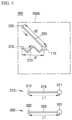
- FIG. 3 is a plan view of a patterned portion of the heat conduction panel according to a first embodiment of the present invention.
- the heat conduction panel 200 may include a patterned portion.
- the patterned portion may include a first patterned portion 210 and a second patterned portion 220.
- the first patterned portion 210 may have a first inner region 211, a first outer region 212, and a first extension 213.
- the first inner region 211 may be disposed at a center of the temperature measurement region 200A, and may be connected to the sensing end 110 of the sensor unit 100.
- the first outer region 212 may be disposed at an outer edge of the temperature measurement region 200A, and may be separated from the first inner region 211 by a first linear distance d1.
- the first extension 213 may connect the first inner region 211 to the first outer region 212.
- the first extension 213 may have a longer length than a distance between the first outer region 212 and the first inner region 211, that is, the first linear distance d1.
- the first extension 213 may extend from the first inner region 211 to the first outer region 212 in an irregular shape such as a zigzag shape or an arc shape in plan view.
- the second patterned portion 220 may have a second inner region 221, a second outer region 222, and a second extension 223.
- the second inner region 221 may be disposed at the center of the temperature measurement region 200A, and may be connected to the sensing end 110 of the sensor unit 100.
- the second outer region 222 may be disposed at the outer edge of the temperature measurement region 200A, and may be separated from the second inner region 221 by a second linear distance d2.
- the second linear distance d2 may be longer than the first linear distance d1.
- the second extension 223 may connect the second inner region 221 to the second outer region 222.
- the second extension 223 may have a longer length than the second linear distance d2.
- the second extension 223 may extend from the second inner region 221 to the second outer region 222 in an irregular shape such as a zigzag shape or an arc shape in plan view.
- the first extension 213 and the second extension 223 may have the same length L1. That is, since there is a difference between the first linear distance d1 and the second linear distance d2, the first extension 213 and the second extension 223 extend in different shapes to have the same length L1, as shown in FIG. 3 .
- the heat transfer rate means the amount of heat transferred per unit time.
- heat transferred from the heat source to the first outer region 212 and heat transferred from the heat source to the second outer region 222 can reach the sensing end 110 at the same time after moving along the first extension 213 and the second extension 223, respectively. Accordingly, the sensor unit 100 can quickly and accurately measure the temperature of the temperature measurement region 200A in a specific amount of time.
- heat transferred to a side of the temperature measurement region, which is relatively close to the sensing end 110, and heat transferred to a corner of the temperature measurement region, which is relatively far from the sensing end 110, can reach the sensing end 110 at the same time after moving along the first extension 213 and the second extension 223, respectively.
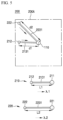
- FIG. 4 is a plan view of a modification of the patterned portion of FIG. 3 .
- an interference structure ST may be disposed at a center of the temperature measurement region 200A defined by the heat conduction panel 200 depending on the type of heat source or the condition of a fire-resistant structure filled with the heat source. Accordingly, the sensing end 110 of the sensor unit 100 needs to be disposed offset from the center of the temperature measurement region 200A.
- the sensing end 110 of the sensor unit 100 is disposed offset from the center of the temperature measurement region 200A, heat transferred to the first outer region 212 separated the first linear distance d1 from the sensing end 110 and heat transferred to the second outer region 212 separated the second linear distance d2 from the sensing end 110 can reach the sensing end 110 at the same time after moving along a first extension 2130 and a second extension 2230, respectively. Accordingly, the sensor unit 100 can quickly and accurately measure the temperature of the temperature measurement region 200A in a specific amount of time.
- FIG. 5 is a plan view of a patterned portion of the heat conduction panel according to a second embodiment of the present invention.
- the patterned portion may include a first patterned portion 210 and a second patterned portion 220, like the patterned portion described above.
- the first patterned portion 210 may have a first inner region 211, a first outer region 212, and a first extension 2131
- the second patterned portion 220 may have a second inner region 221, a second outer region 222, and a second extension 2231. Repeated description thereof will be omitted.
- the first extension 2131 and the second extension 2231 have different lengths corresponding to the difference between the first linear distance d1 and the second linear distance d2.
- the first extension 2131 and the second extension 2231 may be formed of different materials having different heat conductivities. That is, the first extension 2131 may have a first heat conductivity ⁇ 1 and the second extension 2231 may have a second heat conductivity ⁇ 2 greater than the first heat conductivity ⁇ 1.
- FIG. 6 is a plan view of a patterned portion of the heat conduction panel according to a third embodiment of the present invention.
- the patterned portion may include a first patterned portion 210 and a second patterned portion 220, like the patterned portion described above.
- the first patterned portion 210 may have a first inner region 211, a first outer region 212, and a first extension 2132
- the second patterned portion 220 may have a second inner region 221, a second outer region 222, and a second extension 2232. Repeated description thereof will be omitted.
- the first extension 2132 and the second extension 2232 may have different lengths corresponding to the difference between the first linear distance d1 and the second linear distance d2.
- the first extension 2132 and the second extension 2232 may have different areas. That is, the first extension 2132 may have a first area A1 and the second extension 2232 may have a second area A2 larger than the first area A1.
- FIG. 7 is a plan view of a patterned portion of the heat conduction panel according to a fourth embodiment of the present invention.
- the patterned portion may include a first patterned portion 210 and a second patterned portion 220, like the patterned portion described above.
- the first patterned portion 210 may have a first inner region 211, a first outer region 212, and a first extension 2133
- the second patterned portion 220 may have a second inner region 221, a second outer region 221, and a second extension 2233.
- the first patterned portion 210 may further have a first heat collecting portion 214 disposed in the first outer region 212
- the second patterned portion 220 may further have a second heat collecting portion 224 disposed in the second outer region 222.
- the first extension 2133 and the second extension 2233 may have different lengths corresponding to the difference between the first linear distance d1 and the second linear distance d2.
- the first heat collecting portion 214 and the second heat collecting portion 224 may be formed of different materials having different heat conductivities. That is, the first heat collecting portion 214 may have a third heat conductivity and the second heat collecting portion 224 may have a fourth heat conductivity greater than the third heat conductivity.
- heat generated from the heat source can be quickly transferred to the outer region of the heat conduction panel 200 and thus takes less time to reach the sensing end 110.
- settings for the lengths, heat conductivities, and areas of the first extension and the second extension are described as being regulated individually during formation of the first patterned portion 210 and the second patterned portion 220.
- the present invention is not limited thereto and compensation for the difference between heat transfer rates through the first extension and the second extension may be achieved by regulating at least one of the settings for the lengths, heat conductivities, and areas of the first extension and the second extension during formation of the first patterned portion 210 and the second patterned portion 220.
- the settings for the lengths, heat conductivities, and areas of the patterned portions of the heat conduction panel 200 may be appropriately varied depending on the type of heat source, the type of structure filled with the heat source, and the installation position of the sensing end 110.
- FIG. 8 is a plan view of a heat conduction panel without any patterned portion according to a fifth embodiment of the present invention.
- the heat conduction panel 200 does not have any patterned portion, and may be in the form of a flat plate corresponding in shape to a temperature measurement region 200A.
- the temperature measurement region 200A may have a circular shape, wherein the sensing end 110 of the sensor unit 100 may be disposed at a center of the temperature measurement region 200A.
- the heat conduction panel 200 may have a circular shape having a constant radius R1 about the sensing end 110, corresponding to the circular temperature measurement region 200A.
- the circular heat conduction panel 200 having a constant radius R1 about the sensing end 110 can ensure a uniform heat transfer rate from an outer region of the heat conduction panel 200 to the sensing end 110.
- heat transferred from the heat source to different points of the outer region of the heat conduction panel 200 can reach an inner region connected to the sensing end 110 at the same time.
- the present invention is not limited thereto and the circular heat conduction panel 200 having a constant radius R1 about the sensing end 110 may also have a patterned portion.
- the patterned portion may have a radial pattern consisting of multiple sections extending from the inner region connected to the sensing end 110 to the outer region and having the same length, area, and heat conductivity. Accordingly, heat transferred from the heat source to the outer region of the heat conduction panel 200 can more quickly reach the inner region connected to the sensing end 110.
- FIG. 9 is a block diagram of a temperature measurement system according to one embodiment of the present invention.
- the temperature measuring system may include a temperature sensor module 10 and a management module 20.
- the temperature sensor module As the temperature sensor module, the temperature sensor module 10 described above may be used.
- the management module 20 may include a second communication unit.
- the second communication unit may receive temperature information measured and processed by the sensor unit 100 and may transmit a control signal to the sensor unit 100.
- management module 20 may process the temperature information measured and processed by the temperature sensor module 10 and may display information about the temperature of the temperature measurement region 200A in the form of various outputs.
- a manager who operates the management module 20 can effectively manage the operating state of a heat source or a fire-resistant structure filled with the heat source through monitoring of the temperature of the temperature measurement region 200A displayed on the management module 20.
- the management module 20 may be a computer, or may be a tablet PC or smartphone that a manager can carry.
Landscapes
- Physics & Mathematics (AREA)
- General Physics & Mathematics (AREA)
- Measuring Temperature Or Quantity Of Heat (AREA)
Claims (7)
- Temperatursensormodul (10), aufweisend:eine Sensoreinheit (100) mit einem Erfassungsende (110) zur Messung der Temperatur einer Wärmequelle;eine Wärmeleitplatte (200), die aus einem wärmeleitenden Material gebildet ist und einen Temperaturmessbereich (200A) aufweist, der mit dem Erfassungsende (110) verbunden und der Wärmequelle ausgesetzt ist, so dass von der Wärmequelle auf den Temperaturmessbereich (200A) übertragene Wärme entlang einer Oberfläche des Temperaturmessbereichs (200A) zum Erfassungsende (110) hin übertragen wird; undeine Wärmeisolierplatte (300), die in Bezug auf die Wärmeleitplatte (200) der Wärmequelle gegenüberliegend angeordnet ist, um zu verhindern, dass von der Wärmequelle erzeugte Wärme oder auf die Wärmeleitplatte (200) übertragene Wärme an eine Außenseite der Wärmeisolierplatte (300) abgeleitet wird oder um zu verhindern, dass externe Wärme auf die Wärmeleitplatte (200) übertragen wird,wobei die Wärmeleitplatte (200) einen strukturierten Abschnitt aufweist, der zumindest einen Teil des Temperaturmessbereichs (200A) bildet,dadurch gekennzeichnet, dass der strukturierte Abschnitt umfasst:einen ersten strukturierten Abschnitt (210) mit einem ersten inneren Bereich (211), der mit dem Erfassungsende (110) verbunden ist, einem ersten äußeren Bereich (212), der von dem ersten inneren Bereich (211) durch einen ersten linearen Abstand getrennt ist, und einem ersten Fortsatz (2130, 2131, 2132), der den ersten inneren Bereich (211) mit dem ersten äußeren Bereich (212) verbindet; undeinen zweiten strukturierten Abschnitt (220) mit einem zweiten inneren Bereich (221), der mit dem Erfassungsende (110) verbunden ist, einem zweiten äußeren Bereich (222), der von dem zweiten inneren Bereich (221) durch einen zweiten linearen Abstand getrennt ist, der länger als der erste lineare Abstand ist, und einem zweiten Fortsatz (2230, 2231, 2232), der den zweiten inneren Bereich (221) mit dem zweiten äußeren Bereich (222) verbindet.
- Temperatursensormodul (10) nach Anspruch 1, wobei der erste Fortsatz (2130) und der zweite Fortsatz (2230) die gleiche Länge haben.
- Temperatursensormodul (10) nach Anspruch 1, wobei der erste Fortsatz (2131) und der zweite Fortsatz (2231) unterschiedliche Längen aufweisen, wobei der erste Fortsatz (2131) eine erste Wärmeleitfähigkeit aufweist und der zweite Fortsatz (2231) eine zweite Wärmeleitfähigkeit aufweist, die höher ist als die erste Wärmeleitfähigkeit.
- Temperatursensormodul (10) nach Anspruch 1, wobei der erste Fortsatz (2132) und der zweite Fortsatz (2232) unterschiedliche Längen aufweisen, wobei der erste Fortsatz (2132) eine erste Fläche aufweist und der zweite Fortsatz (2232) eine zweite Fläche aufweist, die größer als die erste Fläche ist.
- Temperatursensormodul (10) nach einem der Ansprüche 1 bis 4, wobei die Wärmeleitplatte (200) ferner umfasst: einen Wärmeaufnahmeabschnitt (214), der in dem ersten äußeren Bereich oder dem zweiten äußeren Bereich angeordnet ist, um von der Wärmequelle übertragene Wärme aufzunehmen, wobei der Wärmeaufnahmeabschnitt (214) aus einem Material gebildet ist, das eine höhere Wärmeleitfähigkeit aufweist als der erste strukturierte Abschnitt (210) und der zweite strukturierte Abschnitt (220).
- Temperatursensormodul (10) nach einem der Ansprüche 1 bis 5, wobei die Sensoreinheit ein Thermoelement mit dem Erfassungsende (110) als heißem Übergang und einen Prozessor umfasst, der mit einem kalten Übergang des Thermoelements verbunden ist und eine Temperaturberechnung aus der Thermospannung in Abhängigkeit von einer Temperatur des Thermoelements durchführt.
- Temperaturmesssystem, aufweisend:das Temperatursensormodul (10) nach einem der Ansprüche 1 bis 6; undein Managementmodul (20), das von dem Temperatursensormodul (10) gemessene und verarbeitete Temperaturinformationen empfängt und eine Temperatur des Temperaturmessbereichs (200A) anzeigt.
Applications Claiming Priority (2)
| Application Number | Priority Date | Filing Date | Title |
|---|---|---|---|
| KR20210105371 | 2021-08-10 | ||
| KR1020220024721A KR102781892B1 (ko) | 2021-08-10 | 2022-02-24 | 온도 측정 센서모듈 및 이를 포함하는 온도 측정 시스템 |
Publications (2)
| Publication Number | Publication Date |
|---|---|
| EP4134645A1 EP4134645A1 (de) | 2023-02-15 |
| EP4134645B1 true EP4134645B1 (de) | 2024-07-31 |
Family
ID=82020979
Family Applications (1)
| Application Number | Title | Priority Date | Filing Date |
|---|---|---|---|
| EP22177418.5A Active EP4134645B1 (de) | 2021-08-10 | 2022-06-07 | Temperatursensormodul und temperaturmesssystem damit |
Country Status (5)
| Country | Link |
|---|---|
| US (1) | US12379259B2 (de) |
| EP (1) | EP4134645B1 (de) |
| JP (1) | JP7539716B2 (de) |
| CN (1) | CN115704716B (de) |
| WO (1) | WO2023017951A1 (de) |
Family Cites Families (15)
| Publication number | Priority date | Publication date | Assignee | Title |
|---|---|---|---|---|
| JPS58160324U (ja) | 1982-04-21 | 1983-10-25 | 株式会社日立製作所 | 食品温度検出器 |
| JPH09119872A (ja) * | 1995-10-26 | 1997-05-06 | Toshiba Corp | 温度測定センサ |
| KR20060063405A (ko) | 2004-12-07 | 2006-06-12 | 주식회사 포스코 | 고로의 내부 온도를 측정할 수 있는 다점식 온도 측정용프루브 |
| JP2007157456A (ja) * | 2005-12-02 | 2007-06-21 | Harison Toshiba Lighting Corp | セラミックヒータ、加熱装置、画像形成装置 |
| JP5027573B2 (ja) * | 2006-07-06 | 2012-09-19 | 株式会社小松製作所 | 温度センサおよび温調装置 |
| JP4946484B2 (ja) * | 2007-02-13 | 2012-06-06 | 日本精工株式会社 | 温度センサ及び車両 |
| JP5248360B2 (ja) * | 2009-02-10 | 2013-07-31 | 矢崎総業株式会社 | 温度検出用回路体構造 |
| JP5046198B2 (ja) * | 2010-04-30 | 2012-10-10 | Tdk株式会社 | 温度センサ |
| DE102010030769B4 (de) * | 2010-06-30 | 2013-02-07 | Preh Gmbh | Temperaturfühler zur Messung einer Fahrzeuginnentemperatur |
| JP6160381B2 (ja) * | 2013-09-11 | 2017-07-12 | Tdk株式会社 | 温度センサ |
| JP6314413B2 (ja) | 2013-10-15 | 2018-04-25 | Tdk株式会社 | 温度センサ |
| JP6656284B2 (ja) * | 2018-03-22 | 2020-03-04 | 本田技研工業株式会社 | 車両の電池温度表示装置 |
| JP2020003268A (ja) * | 2018-06-26 | 2020-01-09 | 株式会社オートネットワーク技術研究所 | 基板構造体 |
| KR102704920B1 (ko) * | 2018-10-31 | 2024-09-10 | 주식회사 아모센스 | 패치형 체온계 및 그 시스템 |
| JP7444491B2 (ja) * | 2021-02-25 | 2024-03-06 | エクセロ カンパニー,リミテッド | 送風支管、送風支管の製造方法及び溶解炉送風システム |
-
2022
- 2022-04-12 WO PCT/KR2022/005256 patent/WO2023017951A1/ko not_active Ceased
- 2022-06-07 EP EP22177418.5A patent/EP4134645B1/de active Active
- 2022-06-09 US US17/836,999 patent/US12379259B2/en active Active
- 2022-06-13 CN CN202210666061.6A patent/CN115704716B/zh active Active
- 2022-06-20 JP JP2022098759A patent/JP7539716B2/ja active Active
Also Published As
| Publication number | Publication date |
|---|---|
| CN115704716B (zh) | 2026-01-06 |
| US12379259B2 (en) | 2025-08-05 |
| CN115704716A (zh) | 2023-02-17 |
| US20230047904A1 (en) | 2023-02-16 |
| WO2023017951A1 (ko) | 2023-02-16 |
| JP7539716B2 (ja) | 2024-08-26 |
| EP4134645A1 (de) | 2023-02-15 |
| JP2023025664A (ja) | 2023-02-22 |
Similar Documents
| Publication | Publication Date | Title |
|---|---|---|
| US3018663A (en) | Furnace lining temperature-thickness measuring apparatus | |
| EP2142898B1 (de) | Temperaturerfassungsvorrichtung | |
| CN101343676B (zh) | 高炉炉腔温度在线检测装置及检测方法 | |
| JP2013537486A (ja) | 連鋳鋳型の物理パラメータを測定するための装置 | |
| SE445258B (sv) | Sett att overvaka avnotning av eldfasta veggar i en masugn | |
| ITUB20150948A1 (it) | Elemento di fissaggio, uso di un sensore integrato nell'elemento di fissaggio e metodo per rilevare un flusso termico all'interno di organi meccanici | |
| EP4134645B1 (de) | Temperatursensormodul und temperaturmesssystem damit | |
| JP2769225B2 (ja) | ヒートストリーク発生の予測方法及び温度センサーロール | |
| US12291756B2 (en) | Tuyere stock, method of fabricating the same, and air blast system for melting furnace | |
| CN102401699B (zh) | 温度传感器 | |
| KR102781892B1 (ko) | 온도 측정 센서모듈 및 이를 포함하는 온도 측정 시스템 | |
| JP2000055743A (ja) | 多点計測平均温度計 | |
| US3024657A (en) | Means for determining defects in furnace walls | |
| KR20180066261A (ko) | 용융로에서 전극의 길이 결정 | |
| JP2002339408A5 (de) | ||
| KR102746424B1 (ko) | 송풍지관, 송풍지관의 제조방법 및 용해로 송풍시스템 | |
| JPH0656337B2 (ja) | 金属走行体の温度測定方法およびその装置 | |
| JPS6130012B2 (de) | ||
| JPH10324925A (ja) | 金属帯熱処理炉の異常予測方法及びその装置 | |
| KR20000043425A (ko) | 열유속 측정을 통한 노저 연와두께 측정방법 및 그 장치 | |
| EP3910307A1 (de) | Sensor und system | |
| JPH02118007A (ja) | 高炉炉熱低下予測方法 | |
| JP2008101933A (ja) | 鋼構造物の表面温度測定方法 | |
| JPH0375494A (ja) | 耐火物監視用温度センサ | |
| JPS63312910A (ja) | 高炉炉熱低下予測方法 |
Legal Events
| Date | Code | Title | Description |
|---|---|---|---|
| PUAI | Public reference made under article 153(3) epc to a published international application that has entered the european phase |
Free format text: ORIGINAL CODE: 0009012 |
|
| STAA | Information on the status of an ep patent application or granted ep patent |
Free format text: STATUS: REQUEST FOR EXAMINATION WAS MADE |
|
| 17P | Request for examination filed |
Effective date: 20220607 |
|
| AK | Designated contracting states |
Kind code of ref document: A1 Designated state(s): AL AT BE BG CH CY CZ DE DK EE ES FI FR GB GR HR HU IE IS IT LI LT LU LV MC MK MT NL NO PL PT RO RS SE SI SK SM TR |
|
| RBV | Designated contracting states (corrected) |
Designated state(s): AL AT BE BG CH CY CZ DE DK EE ES FI FR GB GR HR HU IE IS IT LI LT LU LV MC MK MT NL NO PL PT RO RS SE SI SK SM TR |
|
| RAP1 | Party data changed (applicant data changed or rights of an application transferred) |
Owner name: PARK, SEUNG JAE Owner name: EXCELLO CO., LTD. |
|
| GRAP | Despatch of communication of intention to grant a patent |
Free format text: ORIGINAL CODE: EPIDOSNIGR1 |
|
| STAA | Information on the status of an ep patent application or granted ep patent |
Free format text: STATUS: GRANT OF PATENT IS INTENDED |
|
| RIC1 | Information provided on ipc code assigned before grant |
Ipc: G01K 7/02 20210101ALI20240402BHEP Ipc: G01K 1/16 20060101AFI20240402BHEP |
|
| INTG | Intention to grant announced |
Effective date: 20240430 |
|
| GRAS | Grant fee paid |
Free format text: ORIGINAL CODE: EPIDOSNIGR3 |
|
| GRAA | (expected) grant |
Free format text: ORIGINAL CODE: 0009210 |
|
| STAA | Information on the status of an ep patent application or granted ep patent |
Free format text: STATUS: THE PATENT HAS BEEN GRANTED |
|
| AK | Designated contracting states |
Kind code of ref document: B1 Designated state(s): AL AT BE BG CH CY CZ DE DK EE ES FI FR GB GR HR HU IE IS IT LI LT LU LV MC MK MT NL NO PL PT RO RS SE SI SK SM TR |
|
| REG | Reference to a national code |
Ref country code: CH Ref legal event code: EP Ref country code: GB Ref legal event code: FG4D |
|
| REG | Reference to a national code |
Ref country code: DE Ref legal event code: R096 Ref document number: 602022004905 Country of ref document: DE |
|
| REG | Reference to a national code |
Ref country code: IE Ref legal event code: FG4D |
|
| REG | Reference to a national code |
Ref country code: NL Ref legal event code: FP |
|
| REG | Reference to a national code |
Ref country code: LT Ref legal event code: MG9D |
|
| PG25 | Lapsed in a contracting state [announced via postgrant information from national office to epo] |
Ref country code: PT Free format text: LAPSE BECAUSE OF FAILURE TO SUBMIT A TRANSLATION OF THE DESCRIPTION OR TO PAY THE FEE WITHIN THE PRESCRIBED TIME-LIMIT Effective date: 20241202 |
|
| REG | Reference to a national code |
Ref country code: AT Ref legal event code: MK05 Ref document number: 1708878 Country of ref document: AT Kind code of ref document: T Effective date: 20240731 |
|
| PG25 | Lapsed in a contracting state [announced via postgrant information from national office to epo] |
Ref country code: PT Free format text: LAPSE BECAUSE OF FAILURE TO SUBMIT A TRANSLATION OF THE DESCRIPTION OR TO PAY THE FEE WITHIN THE PRESCRIBED TIME-LIMIT Effective date: 20241202 |
|
| PG25 | Lapsed in a contracting state [announced via postgrant information from national office to epo] |
Ref country code: NO Free format text: LAPSE BECAUSE OF FAILURE TO SUBMIT A TRANSLATION OF THE DESCRIPTION OR TO PAY THE FEE WITHIN THE PRESCRIBED TIME-LIMIT Effective date: 20241031 |
|
| PG25 | Lapsed in a contracting state [announced via postgrant information from national office to epo] |
Ref country code: FI Free format text: LAPSE BECAUSE OF FAILURE TO SUBMIT A TRANSLATION OF THE DESCRIPTION OR TO PAY THE FEE WITHIN THE PRESCRIBED TIME-LIMIT Effective date: 20240731 Ref country code: PL Free format text: LAPSE BECAUSE OF FAILURE TO SUBMIT A TRANSLATION OF THE DESCRIPTION OR TO PAY THE FEE WITHIN THE PRESCRIBED TIME-LIMIT Effective date: 20240731 Ref country code: GR Free format text: LAPSE BECAUSE OF FAILURE TO SUBMIT A TRANSLATION OF THE DESCRIPTION OR TO PAY THE FEE WITHIN THE PRESCRIBED TIME-LIMIT Effective date: 20241101 |
|
| PG25 | Lapsed in a contracting state [announced via postgrant information from national office to epo] |
Ref country code: BG Free format text: LAPSE BECAUSE OF FAILURE TO SUBMIT A TRANSLATION OF THE DESCRIPTION OR TO PAY THE FEE WITHIN THE PRESCRIBED TIME-LIMIT Effective date: 20240731 |
|
| PG25 | Lapsed in a contracting state [announced via postgrant information from national office to epo] |
Ref country code: LV Free format text: LAPSE BECAUSE OF FAILURE TO SUBMIT A TRANSLATION OF THE DESCRIPTION OR TO PAY THE FEE WITHIN THE PRESCRIBED TIME-LIMIT Effective date: 20240731 |
|
| PG25 | Lapsed in a contracting state [announced via postgrant information from national office to epo] |
Ref country code: AT Free format text: LAPSE BECAUSE OF FAILURE TO SUBMIT A TRANSLATION OF THE DESCRIPTION OR TO PAY THE FEE WITHIN THE PRESCRIBED TIME-LIMIT Effective date: 20240731 Ref country code: IS Free format text: LAPSE BECAUSE OF FAILURE TO SUBMIT A TRANSLATION OF THE DESCRIPTION OR TO PAY THE FEE WITHIN THE PRESCRIBED TIME-LIMIT Effective date: 20241130 |
|
| PG25 | Lapsed in a contracting state [announced via postgrant information from national office to epo] |
Ref country code: HR Free format text: LAPSE BECAUSE OF FAILURE TO SUBMIT A TRANSLATION OF THE DESCRIPTION OR TO PAY THE FEE WITHIN THE PRESCRIBED TIME-LIMIT Effective date: 20240731 |
|
| PG25 | Lapsed in a contracting state [announced via postgrant information from national office to epo] |
Ref country code: ES Free format text: LAPSE BECAUSE OF FAILURE TO SUBMIT A TRANSLATION OF THE DESCRIPTION OR TO PAY THE FEE WITHIN THE PRESCRIBED TIME-LIMIT Effective date: 20240731 Ref country code: RS Free format text: LAPSE BECAUSE OF FAILURE TO SUBMIT A TRANSLATION OF THE DESCRIPTION OR TO PAY THE FEE WITHIN THE PRESCRIBED TIME-LIMIT Effective date: 20241031 |
|
| PG25 | Lapsed in a contracting state [announced via postgrant information from national office to epo] |
Ref country code: RS Free format text: LAPSE BECAUSE OF FAILURE TO SUBMIT A TRANSLATION OF THE DESCRIPTION OR TO PAY THE FEE WITHIN THE PRESCRIBED TIME-LIMIT Effective date: 20241031 Ref country code: PL Free format text: LAPSE BECAUSE OF FAILURE TO SUBMIT A TRANSLATION OF THE DESCRIPTION OR TO PAY THE FEE WITHIN THE PRESCRIBED TIME-LIMIT Effective date: 20240731 Ref country code: NO Free format text: LAPSE BECAUSE OF FAILURE TO SUBMIT A TRANSLATION OF THE DESCRIPTION OR TO PAY THE FEE WITHIN THE PRESCRIBED TIME-LIMIT Effective date: 20241031 Ref country code: LV Free format text: LAPSE BECAUSE OF FAILURE TO SUBMIT A TRANSLATION OF THE DESCRIPTION OR TO PAY THE FEE WITHIN THE PRESCRIBED TIME-LIMIT Effective date: 20240731 Ref country code: IS Free format text: LAPSE BECAUSE OF FAILURE TO SUBMIT A TRANSLATION OF THE DESCRIPTION OR TO PAY THE FEE WITHIN THE PRESCRIBED TIME-LIMIT Effective date: 20241130 Ref country code: HR Free format text: LAPSE BECAUSE OF FAILURE TO SUBMIT A TRANSLATION OF THE DESCRIPTION OR TO PAY THE FEE WITHIN THE PRESCRIBED TIME-LIMIT Effective date: 20240731 Ref country code: GR Free format text: LAPSE BECAUSE OF FAILURE TO SUBMIT A TRANSLATION OF THE DESCRIPTION OR TO PAY THE FEE WITHIN THE PRESCRIBED TIME-LIMIT Effective date: 20241101 Ref country code: FI Free format text: LAPSE BECAUSE OF FAILURE TO SUBMIT A TRANSLATION OF THE DESCRIPTION OR TO PAY THE FEE WITHIN THE PRESCRIBED TIME-LIMIT Effective date: 20240731 Ref country code: ES Free format text: LAPSE BECAUSE OF FAILURE TO SUBMIT A TRANSLATION OF THE DESCRIPTION OR TO PAY THE FEE WITHIN THE PRESCRIBED TIME-LIMIT Effective date: 20240731 Ref country code: BG Free format text: LAPSE BECAUSE OF FAILURE TO SUBMIT A TRANSLATION OF THE DESCRIPTION OR TO PAY THE FEE WITHIN THE PRESCRIBED TIME-LIMIT Effective date: 20240731 Ref country code: AT Free format text: LAPSE BECAUSE OF FAILURE TO SUBMIT A TRANSLATION OF THE DESCRIPTION OR TO PAY THE FEE WITHIN THE PRESCRIBED TIME-LIMIT Effective date: 20240731 |
|
| PG25 | Lapsed in a contracting state [announced via postgrant information from national office to epo] |
Ref country code: SM Free format text: LAPSE BECAUSE OF FAILURE TO SUBMIT A TRANSLATION OF THE DESCRIPTION OR TO PAY THE FEE WITHIN THE PRESCRIBED TIME-LIMIT Effective date: 20240731 Ref country code: RO Free format text: LAPSE BECAUSE OF FAILURE TO SUBMIT A TRANSLATION OF THE DESCRIPTION OR TO PAY THE FEE WITHIN THE PRESCRIBED TIME-LIMIT Effective date: 20240731 Ref country code: DK Free format text: LAPSE BECAUSE OF FAILURE TO SUBMIT A TRANSLATION OF THE DESCRIPTION OR TO PAY THE FEE WITHIN THE PRESCRIBED TIME-LIMIT Effective date: 20240731 |
|
| PG25 | Lapsed in a contracting state [announced via postgrant information from national office to epo] |
Ref country code: EE Free format text: LAPSE BECAUSE OF FAILURE TO SUBMIT A TRANSLATION OF THE DESCRIPTION OR TO PAY THE FEE WITHIN THE PRESCRIBED TIME-LIMIT Effective date: 20240731 |
|
| PG25 | Lapsed in a contracting state [announced via postgrant information from national office to epo] |
Ref country code: CZ Free format text: LAPSE BECAUSE OF FAILURE TO SUBMIT A TRANSLATION OF THE DESCRIPTION OR TO PAY THE FEE WITHIN THE PRESCRIBED TIME-LIMIT Effective date: 20240731 |
|
| PG25 | Lapsed in a contracting state [announced via postgrant information from national office to epo] |
Ref country code: SK Free format text: LAPSE BECAUSE OF FAILURE TO SUBMIT A TRANSLATION OF THE DESCRIPTION OR TO PAY THE FEE WITHIN THE PRESCRIBED TIME-LIMIT Effective date: 20240731 |
|
| REG | Reference to a national code |
Ref country code: DE Ref legal event code: R097 Ref document number: 602022004905 Country of ref document: DE |
|
| PLBE | No opposition filed within time limit |
Free format text: ORIGINAL CODE: 0009261 |
|
| STAA | Information on the status of an ep patent application or granted ep patent |
Free format text: STATUS: NO OPPOSITION FILED WITHIN TIME LIMIT |
|
| 26N | No opposition filed |
Effective date: 20250501 |
|
| PGFP | Annual fee paid to national office [announced via postgrant information from national office to epo] |
Ref country code: LU Payment date: 20250624 Year of fee payment: 4 Ref country code: NL Payment date: 20250624 Year of fee payment: 4 |
|
| PGFP | Annual fee paid to national office [announced via postgrant information from national office to epo] |
Ref country code: FR Payment date: 20250623 Year of fee payment: 4 |
|
| PG25 | Lapsed in a contracting state [announced via postgrant information from national office to epo] |
Ref country code: SE Free format text: LAPSE BECAUSE OF FAILURE TO SUBMIT A TRANSLATION OF THE DESCRIPTION OR TO PAY THE FEE WITHIN THE PRESCRIBED TIME-LIMIT Effective date: 20240731 |
|
| PGFP | Annual fee paid to national office [announced via postgrant information from national office to epo] |
Ref country code: DE Payment date: 20250630 Year of fee payment: 4 |
|
| PGFP | Annual fee paid to national office [announced via postgrant information from national office to epo] |
Ref country code: IT Payment date: 20250630 Year of fee payment: 4 |
|
| REG | Reference to a national code |
Ref country code: CH Ref legal event code: H13 Free format text: ST27 STATUS EVENT CODE: U-0-0-H10-H13 (AS PROVIDED BY THE NATIONAL OFFICE) Effective date: 20260127 |
|
| PG25 | Lapsed in a contracting state [announced via postgrant information from national office to epo] |
Ref country code: MC Free format text: LAPSE BECAUSE OF FAILURE TO SUBMIT A TRANSLATION OF THE DESCRIPTION OR TO PAY THE FEE WITHIN THE PRESCRIBED TIME-LIMIT Effective date: 20240731 |
|
| REG | Reference to a national code |
Ref country code: BE Ref legal event code: MM Effective date: 20250630 |
|
| PG25 | Lapsed in a contracting state [announced via postgrant information from national office to epo] |
Ref country code: IE Free format text: LAPSE BECAUSE OF NON-PAYMENT OF DUE FEES Effective date: 20250607 |
|
| PG25 | Lapsed in a contracting state [announced via postgrant information from national office to epo] |
Ref country code: BE Free format text: LAPSE BECAUSE OF NON-PAYMENT OF DUE FEES Effective date: 20250630 |
|
| PG25 | Lapsed in a contracting state [announced via postgrant information from national office to epo] |
Ref country code: CH Free format text: LAPSE BECAUSE OF NON-PAYMENT OF DUE FEES Effective date: 20250630 |