EP4134510A1 - Flachbaulüftungstür-fenster-konstruktion - Google Patents
Flachbaulüftungstür-fenster-konstruktion Download PDFInfo
- Publication number
- EP4134510A1 EP4134510A1 EP21807542.2A EP21807542A EP4134510A1 EP 4134510 A1 EP4134510 A1 EP 4134510A1 EP 21807542 A EP21807542 A EP 21807542A EP 4134510 A1 EP4134510 A1 EP 4134510A1
- Authority
- EP
- European Patent Office
- Prior art keywords
- movable sash
- flat
- window structure
- type ventilation
- ventilation door
- Prior art date
- Legal status (The legal status is an assumption and is not a legal conclusion. Google has not performed a legal analysis and makes no representation as to the accuracy of the status listed.)
- Pending
Links
- 238000009423 ventilation Methods 0.000 title claims abstract description 24
- 230000001105 regulatory effect Effects 0.000 claims description 2
- XLYOFNOQVPJJNP-UHFFFAOYSA-N water Substances O XLYOFNOQVPJJNP-UHFFFAOYSA-N 0.000 abstract description 6
- 238000009413 insulation Methods 0.000 abstract description 4
- 238000005096 rolling process Methods 0.000 description 8
- 241000255925 Diptera Species 0.000 description 2
- 238000004140 cleaning Methods 0.000 description 1
- 238000009434 installation Methods 0.000 description 1
- 238000007789 sealing Methods 0.000 description 1
Images


Classifications
-
- E—FIXED CONSTRUCTIONS
- E06—DOORS, WINDOWS, SHUTTERS, OR ROLLER BLINDS IN GENERAL; LADDERS
- E06B—FIXED OR MOVABLE CLOSURES FOR OPENINGS IN BUILDINGS, VEHICLES, FENCES OR LIKE ENCLOSURES IN GENERAL, e.g. DOORS, WINDOWS, BLINDS, GATES
- E06B3/00—Window sashes, door leaves, or like elements for closing wall or like openings; Layout of fixed or moving closures, e.g. windows in wall or like openings; Features of rigidly-mounted outer frames relating to the mounting of wing frames
- E06B3/32—Arrangements of wings characterised by the manner of movement; Arrangements of movable wings in openings; Features of wings or frames relating solely to the manner of movement of the wing
- E06B3/50—Arrangements of wings characterised by the manner of movement; Arrangements of movable wings in openings; Features of wings or frames relating solely to the manner of movement of the wing with more than one kind of movement
- E06B3/5054—Arrangements of wings characterised by the manner of movement; Arrangements of movable wings in openings; Features of wings or frames relating solely to the manner of movement of the wing with more than one kind of movement where the sliding and rotating movements are independent of each other
- E06B3/5063—Arrangements of wings characterised by the manner of movement; Arrangements of movable wings in openings; Features of wings or frames relating solely to the manner of movement of the wing with more than one kind of movement where the sliding and rotating movements are independent of each other the vertical sliding wings having the possibility of an additional rotational movement
-
- E—FIXED CONSTRUCTIONS
- E05—LOCKS; KEYS; WINDOW OR DOOR FITTINGS; SAFES
- E05D—HINGES OR SUSPENSION DEVICES FOR DOORS, WINDOWS OR WINGS
- E05D15/00—Suspension arrangements for wings
- E05D15/16—Suspension arrangements for wings for wings sliding vertically more or less in their own plane
- E05D15/18—Suspension arrangements for wings for wings sliding vertically more or less in their own plane consisting of two or more independent parts, movable each in its own guides
-
- E—FIXED CONSTRUCTIONS
- E05—LOCKS; KEYS; WINDOW OR DOOR FITTINGS; SAFES
- E05D—HINGES OR SUSPENSION DEVICES FOR DOORS, WINDOWS OR WINGS
- E05D15/00—Suspension arrangements for wings
- E05D15/16—Suspension arrangements for wings for wings sliding vertically more or less in their own plane
- E05D15/20—Suspension arrangements for wings for wings sliding vertically more or less in their own plane movable out of one plane into a second parallel plane
-
- E—FIXED CONSTRUCTIONS
- E05—LOCKS; KEYS; WINDOW OR DOOR FITTINGS; SAFES
- E05D—HINGES OR SUSPENSION DEVICES FOR DOORS, WINDOWS OR WINGS
- E05D15/00—Suspension arrangements for wings
- E05D15/16—Suspension arrangements for wings for wings sliding vertically more or less in their own plane
- E05D15/22—Suspension arrangements for wings for wings sliding vertically more or less in their own plane allowing an additional movement
-
- E—FIXED CONSTRUCTIONS
- E05—LOCKS; KEYS; WINDOW OR DOOR FITTINGS; SAFES
- E05F—DEVICES FOR MOVING WINGS INTO OPEN OR CLOSED POSITION; CHECKS FOR WINGS; WING FITTINGS NOT OTHERWISE PROVIDED FOR, CONCERNED WITH THE FUNCTIONING OF THE WING
- E05F17/00—Special devices for shifting a plurality of wings operated simultaneously
-
- E—FIXED CONSTRUCTIONS
- E06—DOORS, WINDOWS, SHUTTERS, OR ROLLER BLINDS IN GENERAL; LADDERS
- E06B—FIXED OR MOVABLE CLOSURES FOR OPENINGS IN BUILDINGS, VEHICLES, FENCES OR LIKE ENCLOSURES IN GENERAL, e.g. DOORS, WINDOWS, BLINDS, GATES
- E06B3/00—Window sashes, door leaves, or like elements for closing wall or like openings; Layout of fixed or moving closures, e.g. windows in wall or like openings; Features of rigidly-mounted outer frames relating to the mounting of wing frames
- E06B3/32—Arrangements of wings characterised by the manner of movement; Arrangements of movable wings in openings; Features of wings or frames relating solely to the manner of movement of the wing
- E06B3/34—Arrangements of wings characterised by the manner of movement; Arrangements of movable wings in openings; Features of wings or frames relating solely to the manner of movement of the wing with only one kind of movement
- E06B3/42—Sliding wings; Details of frames with respect to guiding
- E06B3/44—Vertically-sliding wings
- E06B3/4415—Double-hung, i.e. with two vertical sliding panels
-
- E—FIXED CONSTRUCTIONS
- E05—LOCKS; KEYS; WINDOW OR DOOR FITTINGS; SAFES
- E05Y—INDEXING SCHEME ASSOCIATED WITH SUBCLASSES E05D AND E05F, RELATING TO CONSTRUCTION ELEMENTS, ELECTRIC CONTROL, POWER SUPPLY, POWER SIGNAL OR TRANSMISSION, USER INTERFACES, MOUNTING OR COUPLING, DETAILS, ACCESSORIES, AUXILIARY OPERATIONS NOT OTHERWISE PROVIDED FOR, APPLICATION THEREOF
- E05Y2201/00—Constructional elements; Accessories therefor
- E05Y2201/60—Suspension or transmission members; Accessories therefor
- E05Y2201/622—Suspension or transmission members elements
- E05Y2201/644—Flexible elongated pulling elements
- E05Y2201/654—Cables
-
- E—FIXED CONSTRUCTIONS
- E05—LOCKS; KEYS; WINDOW OR DOOR FITTINGS; SAFES
- E05Y—INDEXING SCHEME ASSOCIATED WITH SUBCLASSES E05D AND E05F, RELATING TO CONSTRUCTION ELEMENTS, ELECTRIC CONTROL, POWER SUPPLY, POWER SIGNAL OR TRANSMISSION, USER INTERFACES, MOUNTING OR COUPLING, DETAILS, ACCESSORIES, AUXILIARY OPERATIONS NOT OTHERWISE PROVIDED FOR, APPLICATION THEREOF
- E05Y2201/00—Constructional elements; Accessories therefor
- E05Y2201/60—Suspension or transmission members; Accessories therefor
- E05Y2201/622—Suspension or transmission members elements
- E05Y2201/658—Members cooperating with flexible elongated pulling elements
- E05Y2201/672—Tensioners, tension sensors
-
- E—FIXED CONSTRUCTIONS
- E05—LOCKS; KEYS; WINDOW OR DOOR FITTINGS; SAFES
- E05Y—INDEXING SCHEME ASSOCIATED WITH SUBCLASSES E05D AND E05F, RELATING TO CONSTRUCTION ELEMENTS, ELECTRIC CONTROL, POWER SUPPLY, POWER SIGNAL OR TRANSMISSION, USER INTERFACES, MOUNTING OR COUPLING, DETAILS, ACCESSORIES, AUXILIARY OPERATIONS NOT OTHERWISE PROVIDED FOR, APPLICATION THEREOF
- E05Y2900/00—Application of doors, windows, wings or fittings thereof
- E05Y2900/10—Application of doors, windows, wings or fittings thereof for buildings or parts thereof
- E05Y2900/13—Type of wing
- E05Y2900/148—Windows
Definitions
- the present invention relates to a door-window, in particular a flat-type ventilation door-window structure with ventilation and improved sound and water tightness.
- a flat-type ventilation door-window structure includes a frame, a first movable sash and a second movable sash.
- the first movable sash and/or the second movable sash can slide up and down in an opening of the frame.
- a first guide device and a second guide device are respectively provided between the first movable sash or the second movable sash and the frame. The first guide device and the second guide device can guide the first movable sash or the second movable sash to change the sliding path.
- the advantage of the present invention is as follows.
- the main object of the present invention is providing a flat-type ventilation door-window structure, which can prevent the sound, rain and air from entering into room through the gaps between the first or second movable sash and the frame by overlapping up and down the first and second sashes.
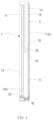
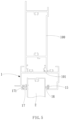
- the flat-type ventilation door-window structure includes a frame 1, a first movable sash 2, a second movable sash 3 and at least one linkage device 4.
- the frame 1 comprises an opening 11 in which the first movable sash 2 and the second movable sash 3 are housed.
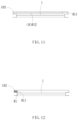
- the bottom surface 21 of the first movable sash 2 and the top surface 31 of the second movable sash 3 are opposite to each other and are planar (as shown in Fig.1 ).
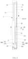
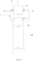
- the Linkage device 4 is provided between the frame 1, the first movable sash 2 and the second movable sash 3, so that when one sash moves up and down, the other sash is made to move up and down in opposite direction in the opening 11 of the frame 1, as shown in Fig.2 ;
- the frame 1 is provided with a first sliding groove 12, a second sliding groove 13 and a third chute (14) arranged between the first sliding groove 12and the second groove 13 on at least one side, wherein the first movable sash 2 and the second movable sash 3 slides in the first sliding groove 12 and the second sliding groove 13 respectively.
- the linkage device 4 has at least a wheel 41 and a cord 42.
- the wheel 41 is arranged in the first sliding groove 12 of the frame 1.
- the two ends of the cord 42 pass around the wheel 41 and are arranged on the sides of the first movable sash 2 and the second movable sash 3 respectively opposite to the inner edge of the frame 1.
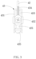
- a cord tightness regulator 43 is provided at where the cord 42 is connected with the first movable sash 2 and includes at least a body 431 having a recessed slot 433 and an adjusting seat 432 housed in the recessed slot 433, and the adjusting seat 432 is provided with a cord fixing element 434 on which said cord 42 is fixed, and with a regulating screw 435 which passes through the said body 431, so that the user can adjust the tightness of the cord 42 directly from outside of the body 431.
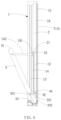
- the second movable sash 3 is provided with a first guide device 300 and a second guide device 400 near the inner edge of the frame 1.
- the first guide device 300 has at least a first guide protrusion 32 and a first guide groove 331.
- the second guide device 400 comprises a second guide protrusion 44 and a second guide groove 332.
- a pivoting tab 321 is provided between the first protrusion 32 and the second guide protrusion.
- the other end of the cord 42 is fixed on the second guide protrusion 44.
- At least one guide block 33 is provided at a side of the frame 1 opposite to the first guide protrusion 32 of the second movable sash 3.
- the guide block 33 is provided with the first guide groove 331 and the second guide groove 332, wherein the tops of the slots of the first guide groove 331 and the second guide groove 332 are respectively communicated with the second sliding groove 13 and the first sliding groove 12.
- the first guide groove 331 and the second guide groove 332 are slots formed by curving of the top of the block 33 towards the inside of the opening 11.
- the first guide protrusion 32 of the second movable sash 3 slides in the first guiding groove 331 of the guide block 33, so that when slide upward, the second movable sash 3 can obliquely moves up along the first guiding groove 331 without contacting the first movable sash 2, and when slide downward, the sliding speed of the second movable sash 3 can be slowed down, due to the arcing action of the second guiding groove 332.
- the second guide protrusion 44 of the second movable sash 3 slides in the second guiding groove 332 of the guide block 33, the speed of sliding down of the second movable sash 3 can also be slowed down by the arcing action of the second guiding groove 332.
- the first sliding groove 12 of the frame 1 is provided with a slot 121 recessed inwardly at a side wall which slides up and down with respect to the second guide protrusion 44.
- a partial wheel of the second guide protrusion 44 is limited in the first sliding groove 12 by the slot 121, so that the stability of the sliding movement of the second movable sash 3 in the second sliding groove 13 is increased, and without risk of shifting or sliding out of the second sliding groove 13.
- the third sliding groove 14 is provided with a sliding block 141 including a connecting rod 142, and one end of the connecting rod 142 is connected to the second movable sash3.
- the inner edge of the frame 1 is provided with a first extension 15 at one side relative to the first movable sash 2 and the second movable sash 3 and a first seal member 16 is provided on the first extension 15.
- a plurality of first pushing members 17 are provided on the inner edge of the frame 1 at a distance from the first seal member 16.
- the first pushing member 17 is provided with a slope 171, when the first movable sash 2 and/or the second movable sash 3 are reached to the first pushing member 17, the two sashes can be pushed towards the first seal member 16 along the slope 171, so that the first movable sash 2 and/or the second movable sash 3 can be fitted tightly with the first seal member 16, thus, an excellent sound insulation, water tightness and air tightness can be got between the first movable sash 2, the second movable sash 3 and the frame 1. As shown in Fig.
- the frame 1 when the frame 1 is implemented on the door, the frame 1 further comprises an outer rim 100, and at least a third sealing strip 101 is provided between the frame 1 and the outer rim 100, so that the present embodiment may not have problems of reducing the water tightness, air tightness and sound insulation.
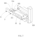
- At least one positioning device 5 is provided on the top surface 31 of the second movable sash 3, and the positioning device 5 including at least a base 51 and a positioning member 52.
- the base 51 is provided on the top surface 31 of the second movable sash 3 near the second sliding groove 13 of the frame 1, and is provided with a slide rail 511 on the top surface.
- the positioning member 52 is placed in the slide rail 511 and can slide in it.
- the positioning member 52 is provided with a receiving groove 521, and a first stopping portion 512 and a second stopping portion 513 protrude from the seat 51 at a position opposite to the receiving groove 521.
- An elastic member 522 is provided between the first stopping portion 512 and the wall of the receiving groove 521.
- An abutment is formed by the second stopping portion 513 and the receiving groove 521.
- One end of positioning member 52 near the side of the frame 1 forms a positioning portion 523, and the other end is a fixing rod 524 arranged with a snap hole 525, and the base 51 is arranged with a snap protrusion 514 opposite to the snap hole 525.
- the fixing rod 524 can be toggled upwards, so that the snap protrusion 514 can depart from the snap hole 525, and make the positioning portion 523 abut against the second sliding groove 13 of the frame 1 by the elastic force of the elastic member 522, and just form and abutment between the positioning portion 523 and the the second sliding groove 13 of the frame 1 .
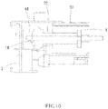
- At least one forcing means 6 is further provided on the top surface 31 of the second movable sash 3.
- the forcing device 6 has at least a lever 61, a lead 62 and a connecting lever 63 connected between the lever 61 and the lead 62.
- the lead 62 is arranged inside the top surface 31 of the second movable sash 3 and the connecting lever 63 is in a shape of L.
- a second resilient pushing member 18 is provided at the inner edge of the frame 1 near one end of the lever 61.
- the second pushing member 18 can move the lever 61, and make the second movable sash 3 move toward the second extension 22 of the first movable sash 2, as indicated by the imaginary line in Fig.10 , thus, allows the second seal member 23 to more closely conform to the second movable sash 3 and the second extension 22 of the first movable sash 2, thereby increase the water tightness and air tightness between the first movable sash 2 and the second movable sash 3.
- the first seal member 16 and the second seal member 23 are rubber strips, but not limited to the foregoing, all structures having sound insulation, air tightness and air tightness are falling within the scope of this application.
- the frame 1 is provided with a screen 7 and/or an antiriot net 9 at one side, so that the present embodiment can prevent the external mosquitoes from entering into the room and/or prevent anyone from intrusion.
- the screen 7 and/or the antiriot net 9 may be a hidden screen 8, such as a folding screen 81 or a rolling bar screen 82, so that the user can pull down the hidden screen 8 to prevent light and mosquitoes from entering into room.
- the folding screen 81 has at least a movable frame 811 and a screen 812, and both sides of the screen 812 are mounted on the movable frame 811 and the side of the frame 1 respectively, or one end of the screen 812 is provided with a fixing member (not shown) to facilitate the mounting of the end on the side of the frame 1.
- the rolling bar screen 82 has at least a rolling bar 821, a screen 822 and a movable frame 823, wherein the rolling bar 821 is provided on the side of the frame 1, and the ends of the screen 822 are provided on the rolling bar 821 and movable frame 823 respectively.
- the screen 822 can extend or retract by pulling the movable frame 823.
- the frame 1 is provided with a recessed slot 102 at the position where the hidden screen 8 is housed, and the folding screen 81 and rolling bar screen 82 can be completely hidden in the recessed slot 102.
Landscapes
- Engineering & Computer Science (AREA)
- Civil Engineering (AREA)
- Structural Engineering (AREA)
- Mechanical Engineering (AREA)
- Specific Sealing Or Ventilating Devices For Doors And Windows (AREA)
- Window Of Vehicle (AREA)
- Wing Frames And Configurations (AREA)
- Refrigerator Housings (AREA)
- Seal Device For Vehicle (AREA)
Applications Claiming Priority (3)
| Application Number | Priority Date | Filing Date | Title |
|---|---|---|---|
| TW108118309 | 2019-05-24 | ||
| CN202010424312.0A CN111980556B (zh) | 2019-05-24 | 2020-05-19 | 兼具通风及可提升隔音水气密的平面式通风门窗结构 |
| PCT/CN2021/081511 WO2021232917A1 (zh) | 2019-05-24 | 2021-03-18 | 平面式通风门窗结构 |
Publications (2)
| Publication Number | Publication Date |
|---|---|
| EP4134510A1 true EP4134510A1 (de) | 2023-02-15 |
| EP4134510A4 EP4134510A4 (de) | 2023-11-15 |
Family
ID=74668347
Family Applications (1)
| Application Number | Title | Priority Date | Filing Date |
|---|---|---|---|
| EP21807542.2A Pending EP4134510A4 (de) | 2019-05-24 | 2021-03-18 | Flachbaulüftungstür-fenster-konstruktion |
Country Status (6)
| Country | Link |
|---|---|
| US (1) | US11898398B2 (de) |
| EP (1) | EP4134510A4 (de) |
| JP (1) | JP2023527277A (de) |
| AU (1) | AU2021274437B2 (de) |
| TW (1) | TWI820269B (de) |
| WO (1) | WO2021232917A1 (de) |
Family Cites Families (27)
| Publication number | Priority date | Publication date | Assignee | Title |
|---|---|---|---|---|
| US1533048A (en) * | 1922-01-30 | 1925-04-07 | Sustarsic Mike | Sliding and swinging window sashes |
| DE2503802C2 (de) * | 1975-01-30 | 1986-01-30 | Götz Metallbau GmbH, 8360 Deggendorf | Vertikalschiebefenster |
| DE2601969C3 (de) * | 1976-01-20 | 1979-10-04 | Eltreva Ag, Aesch (Schweiz) | Vertikalschiebefenster |
| DE2724149C2 (de) * | 1977-05-27 | 1987-04-16 | Götz Metallbau GmbH, 8360 Deggendorf | Vertikalschiebefenster |
| CA2011239C (en) * | 1990-03-01 | 2000-10-17 | Dominique Dallaire | Construction kit for horizontally and vertically sliding window assemblies |
| US5222541A (en) * | 1992-07-22 | 1993-06-29 | Kelley Company, Inc. | Industrial door having releasable beam and tension bracket retention mechanism |
| DE4402464C1 (de) * | 1994-01-28 | 1995-05-04 | Goetz Entwicklung & Lizenz | Horizontalschiebefenster mit mindestens einem quer zur Rahmenebene bewegbaren Schiebeflügel |
| GB9415390D0 (en) * | 1994-07-29 | 1994-09-21 | Bkl Extrusions Ltd | Window structure |
| TW498924U (en) | 2001-11-23 | 2002-08-11 | Ming-Huang Jang | Door panel structure able for improving air current |
| HU223805B1 (hu) * | 2002-02-14 | 2005-01-28 | Mária Rónay | Csúszó ablakszerkezet |
| TWM250028U (en) | 2003-12-12 | 2004-11-11 | Ming-Huang Chang | Door panel structure able to promote air ventilation |
| TWM274437U (en) | 2005-04-06 | 2005-09-01 | Ming-Huang Jang | Door plank structure allowing enhancing air convection rate |
| TWI263731B (en) * | 2005-10-27 | 2006-10-11 | Ruei-Wen Wang | Air-tight windows of horizontally sliding type |
| US7571568B2 (en) * | 2006-01-10 | 2009-08-11 | Ykk Corporation Of America | Sash windows |
| CN101553376B (zh) * | 2006-10-30 | 2012-01-04 | 皮尔金顿北美公司 | 带有水平滑动件的车辆窗户组件及制造该组件的方法 |
| ES2311418B1 (es) * | 2007-07-27 | 2010-01-05 | Enrique Lago Palacios | Ventana de guillotina perfeccionada. |
| US8220846B2 (en) * | 2008-08-15 | 2012-07-17 | Vision Industries Group, Inc. | Latch for tiltable sash windows |
| JP5384433B2 (ja) * | 2010-06-14 | 2014-01-08 | 株式会社Lixil | 上げ下げ窓 |
| US8631850B2 (en) * | 2011-02-08 | 2014-01-21 | Lake City Windows | Window assembly |
| GB2490525B (en) * | 2011-05-04 | 2016-10-19 | Caldwell Hardware (Uk) Ltd | Window restrictor |
| CN102486072B (zh) * | 2011-11-22 | 2014-06-04 | 厦门明昌兴金属工业有限公司 | 自重双动式活动窗 |
| US8978303B1 (en) * | 2012-10-18 | 2015-03-17 | Hughes Supply And Mfg. Co. Of Thomasville, Inc. | Window sash tilt latch and method |
| TWI678458B (zh) * | 2015-12-25 | 2019-12-01 | 日商綿半解決方案股份有限公司 | 大開口窗框 |
| US10443283B2 (en) * | 2017-06-29 | 2019-10-15 | Veka, Inc. | Single hung window construction with an upper fixed lite of glass and a movable bottom sash being generally coplanar |
| US11193318B2 (en) * | 2017-09-21 | 2021-12-07 | Amesbury Group, Inc. | Window balance shoes for a pivotable window |
| CN109339651B (zh) * | 2018-10-29 | 2023-09-29 | 辽宁雨虹门窗有限公司 | 一种多方位开启的自动窗 |
| CN111980556B (zh) * | 2019-05-24 | 2022-12-06 | 清展科技股份有限公司 | 兼具通风及可提升隔音水气密的平面式通风门窗结构 |
-
2019
- 2019-12-11 TW TW108145735A patent/TWI820269B/zh active
-
2021
- 2021-03-18 WO PCT/CN2021/081511 patent/WO2021232917A1/zh not_active Ceased
- 2021-03-18 JP JP2022569269A patent/JP2023527277A/ja active Pending
- 2021-03-18 US US17/924,097 patent/US11898398B2/en active Active
- 2021-03-18 AU AU2021274437A patent/AU2021274437B2/en active Active
- 2021-03-18 EP EP21807542.2A patent/EP4134510A4/de active Pending
Also Published As
| Publication number | Publication date |
|---|---|
| US20230175313A1 (en) | 2023-06-08 |
| AU2021274437B2 (en) | 2024-09-26 |
| WO2021232917A1 (zh) | 2021-11-25 |
| JP2023527277A (ja) | 2023-06-28 |
| TWI820269B (zh) | 2023-11-01 |
| TW202043603A (zh) | 2020-12-01 |
| US11898398B2 (en) | 2024-02-13 |
| AU2021274437A1 (en) | 2023-01-19 |
| EP4134510A4 (de) | 2023-11-15 |
Similar Documents
| Publication | Publication Date | Title |
|---|---|---|
| US10520206B2 (en) | Window air conditioner | |
| KR102012013B1 (ko) | 단열형 창호 구조물 | |
| KR102602235B1 (ko) | 완충장치 및 이를 포함하는 창호 | |
| US9890586B2 (en) | Sunshade structure | |
| KR20110090253A (ko) | 방화문의 가스켓 오토씰링 장치 | |
| WO2016000498A1 (zh) | 一种门窗 | |
| KR20180015197A (ko) | 창문 개폐 정도에 따라 기밀성이 조절되는 창호 구조체 | |
| JP5760141B2 (ja) | エアシールドウィンドウ | |
| KR102633856B1 (ko) | 레일 조립식 미서기 창호 | |
| US11898398B2 (en) | Flat-type ventilation door-window structure | |
| JP2021001510A (ja) | 建具 | |
| KR102599548B1 (ko) | 창호의 기밀장치 및 이를 포함한 창호 | |
| CN104963615A (zh) | 门缝密封装置 | |
| KR101472225B1 (ko) | 창호용 방풍부재, 이를 가지는 창호 프레임 및 방풍부재의 시공방법 | |
| JP6463148B2 (ja) | ドアセット | |
| KR101868960B1 (ko) | 단열복합창용 단열 방풍장치 | |
| KR20200137415A (ko) | 창호용 틈새 방지구 | |
| JP6711648B2 (ja) | 引違いサッシの断熱構造 | |
| KR101606751B1 (ko) | 풍지 겸용 추락방지 구조를 구비한 미서기창호 | |
| KR20190071306A (ko) | 창호 시스템 | |
| KR20190068783A (ko) | 기밀커버 | |
| KR101819888B1 (ko) | 창문과 창틀의 기밀결합구조 | |
| KR100908605B1 (ko) | 개폐기용 가이드 브라켓 | |
| KR102735725B1 (ko) | 창호용 방충부재 | |
| KR101991060B1 (ko) | 기밀유지장치 |
Legal Events
| Date | Code | Title | Description |
|---|---|---|---|
| STAA | Information on the status of an ep patent application or granted ep patent |
Free format text: STATUS: THE INTERNATIONAL PUBLICATION HAS BEEN MADE |
|
| PUAI | Public reference made under article 153(3) epc to a published international application that has entered the european phase |
Free format text: ORIGINAL CODE: 0009012 |
|
| STAA | Information on the status of an ep patent application or granted ep patent |
Free format text: STATUS: REQUEST FOR EXAMINATION WAS MADE |
|
| 17P | Request for examination filed |
Effective date: 20221111 |
|
| AK | Designated contracting states |
Kind code of ref document: A1 Designated state(s): AL AT BE BG CH CY CZ DE DK EE ES FI FR GB GR HR HU IE IS IT LI LT LU LV MC MK MT NL NO PL PT RO RS SE SI SK SM TR |
|
| DAV | Request for validation of the european patent (deleted) | ||
| DAX | Request for extension of the european patent (deleted) | ||
| A4 | Supplementary search report drawn up and despatched |
Effective date: 20231016 |
|
| RIC1 | Information provided on ipc code assigned before grant |
Ipc: E06B 3/44 20060101ALI20231010BHEP Ipc: E06B 3/42 20060101ALI20231010BHEP Ipc: E05D 15/22 20060101ALI20231010BHEP Ipc: E05D 15/48 20060101ALI20231010BHEP Ipc: E06B 3/50 20060101AFI20231010BHEP |