EP4130210B1 - Schmierfettzusammensetzung - Google Patents
Schmierfettzusammensetzung Download PDFInfo
- Publication number
- EP4130210B1 EP4130210B1 EP21780915.1A EP21780915A EP4130210B1 EP 4130210 B1 EP4130210 B1 EP 4130210B1 EP 21780915 A EP21780915 A EP 21780915A EP 4130210 B1 EP4130210 B1 EP 4130210B1
- Authority
- EP
- European Patent Office
- Prior art keywords
- grease composition
- mass
- base oil
- viscosity
- composition according
- Prior art date
- Legal status (The legal status is an assumption and is not a legal conclusion. Google has not performed a legal analysis and makes no representation as to the accuracy of the status listed.)
- Active
Links
Images

Classifications
-
- C—CHEMISTRY; METALLURGY
- C10—PETROLEUM, GAS OR COKE INDUSTRIES; TECHNICAL GASES CONTAINING CARBON MONOXIDE; FUELS; LUBRICANTS; PEAT
- C10M—LUBRICATING COMPOSITIONS; USE OF CHEMICAL SUBSTANCES EITHER ALONE OR AS LUBRICATING INGREDIENTS IN A LUBRICATING COMPOSITION
- C10M169/00—Lubricating compositions characterised by containing as components a mixture of at least two types of ingredient selected from base-materials, thickeners or additives, covered by the preceding groups, each of these compounds being essential
- C10M169/02—Mixtures of base-materials and thickeners
-
- C—CHEMISTRY; METALLURGY
- C10—PETROLEUM, GAS OR COKE INDUSTRIES; TECHNICAL GASES CONTAINING CARBON MONOXIDE; FUELS; LUBRICANTS; PEAT
- C10M—LUBRICATING COMPOSITIONS; USE OF CHEMICAL SUBSTANCES EITHER ALONE OR AS LUBRICATING INGREDIENTS IN A LUBRICATING COMPOSITION
- C10M101/00—Lubricating compositions characterised by the base-material being a mineral or fatty oil
- C10M101/02—Petroleum fractions
-
- C—CHEMISTRY; METALLURGY
- C10—PETROLEUM, GAS OR COKE INDUSTRIES; TECHNICAL GASES CONTAINING CARBON MONOXIDE; FUELS; LUBRICANTS; PEAT
- C10M—LUBRICATING COMPOSITIONS; USE OF CHEMICAL SUBSTANCES EITHER ALONE OR AS LUBRICATING INGREDIENTS IN A LUBRICATING COMPOSITION
- C10M105/00—Lubricating compositions characterised by the base-material being a non-macromolecular organic compound
- C10M105/02—Well-defined hydrocarbons
- C10M105/04—Well-defined hydrocarbons aliphatic
-
- C—CHEMISTRY; METALLURGY
- C10—PETROLEUM, GAS OR COKE INDUSTRIES; TECHNICAL GASES CONTAINING CARBON MONOXIDE; FUELS; LUBRICANTS; PEAT
- C10M—LUBRICATING COMPOSITIONS; USE OF CHEMICAL SUBSTANCES EITHER ALONE OR AS LUBRICATING INGREDIENTS IN A LUBRICATING COMPOSITION
- C10M107/00—Lubricating compositions characterised by the base-material being a macromolecular compound
- C10M107/02—Hydrocarbon polymers; Hydrocarbon polymers modified by oxidation
-
- C—CHEMISTRY; METALLURGY
- C10—PETROLEUM, GAS OR COKE INDUSTRIES; TECHNICAL GASES CONTAINING CARBON MONOXIDE; FUELS; LUBRICANTS; PEAT
- C10M—LUBRICATING COMPOSITIONS; USE OF CHEMICAL SUBSTANCES EITHER ALONE OR AS LUBRICATING INGREDIENTS IN A LUBRICATING COMPOSITION
- C10M111/00—Lubrication compositions characterised by the base-material being a mixture of two or more compounds covered by more than one of the main groups C10M101/00 - C10M109/00, each of these compounds being essential
- C10M111/04—Lubrication compositions characterised by the base-material being a mixture of two or more compounds covered by more than one of the main groups C10M101/00 - C10M109/00, each of these compounds being essential at least one of them being a macromolecular organic compound
-
- C—CHEMISTRY; METALLURGY
- C10—PETROLEUM, GAS OR COKE INDUSTRIES; TECHNICAL GASES CONTAINING CARBON MONOXIDE; FUELS; LUBRICANTS; PEAT
- C10M—LUBRICATING COMPOSITIONS; USE OF CHEMICAL SUBSTANCES EITHER ALONE OR AS LUBRICATING INGREDIENTS IN A LUBRICATING COMPOSITION
- C10M115/00—Lubricating compositions characterised by the thickener being a non-macromolecular organic compound other than a carboxylic acid or salt thereof
- C10M115/08—Lubricating compositions characterised by the thickener being a non-macromolecular organic compound other than a carboxylic acid or salt thereof containing nitrogen
-
- C—CHEMISTRY; METALLURGY
- C10—PETROLEUM, GAS OR COKE INDUSTRIES; TECHNICAL GASES CONTAINING CARBON MONOXIDE; FUELS; LUBRICANTS; PEAT
- C10M—LUBRICATING COMPOSITIONS; USE OF CHEMICAL SUBSTANCES EITHER ALONE OR AS LUBRICATING INGREDIENTS IN A LUBRICATING COMPOSITION
- C10M135/00—Lubricating compositions characterised by the additive being an organic non-macromolecular compound containing sulfur, selenium or tellurium
- C10M135/12—Thio-acids; Thiocyanates; Derivatives thereof
- C10M135/14—Thio-acids; Thiocyanates; Derivatives thereof having a carbon-to-sulfur double bond
- C10M135/18—Thio-acids; Thiocyanates; Derivatives thereof having a carbon-to-sulfur double bond thiocarbamic type, e.g. containing the groups
-
- C—CHEMISTRY; METALLURGY
- C10—PETROLEUM, GAS OR COKE INDUSTRIES; TECHNICAL GASES CONTAINING CARBON MONOXIDE; FUELS; LUBRICANTS; PEAT
- C10M—LUBRICATING COMPOSITIONS; USE OF CHEMICAL SUBSTANCES EITHER ALONE OR AS LUBRICATING INGREDIENTS IN A LUBRICATING COMPOSITION
- C10M137/00—Lubricating compositions characterised by the additive being an organic non-macromolecular compound containing phosphorus
- C10M137/02—Lubricating compositions characterised by the additive being an organic non-macromolecular compound containing phosphorus having no phosphorus-to-carbon bond
- C10M137/04—Phosphate esters
- C10M137/08—Ammonium or amine salts
-
- C—CHEMISTRY; METALLURGY
- C10—PETROLEUM, GAS OR COKE INDUSTRIES; TECHNICAL GASES CONTAINING CARBON MONOXIDE; FUELS; LUBRICANTS; PEAT
- C10M—LUBRICATING COMPOSITIONS; USE OF CHEMICAL SUBSTANCES EITHER ALONE OR AS LUBRICATING INGREDIENTS IN A LUBRICATING COMPOSITION
- C10M137/00—Lubricating compositions characterised by the additive being an organic non-macromolecular compound containing phosphorus
- C10M137/02—Lubricating compositions characterised by the additive being an organic non-macromolecular compound containing phosphorus having no phosphorus-to-carbon bond
- C10M137/04—Phosphate esters
- C10M137/10—Thio derivatives
- C10M137/105—Thio derivatives not containing metal
-
- C—CHEMISTRY; METALLURGY
- C10—PETROLEUM, GAS OR COKE INDUSTRIES; TECHNICAL GASES CONTAINING CARBON MONOXIDE; FUELS; LUBRICANTS; PEAT
- C10M—LUBRICATING COMPOSITIONS; USE OF CHEMICAL SUBSTANCES EITHER ALONE OR AS LUBRICATING INGREDIENTS IN A LUBRICATING COMPOSITION
- C10M141/00—Lubricating compositions characterised by the additive being a mixture of two or more compounds covered by more than one of the main groups C10M125/00 - C10M139/00, each of these compounds being essential
- C10M141/10—Lubricating compositions characterised by the additive being a mixture of two or more compounds covered by more than one of the main groups C10M125/00 - C10M139/00, each of these compounds being essential at least one of them being an organic phosphorus-containing compound
-
- C—CHEMISTRY; METALLURGY
- C10—PETROLEUM, GAS OR COKE INDUSTRIES; TECHNICAL GASES CONTAINING CARBON MONOXIDE; FUELS; LUBRICANTS; PEAT
- C10M—LUBRICATING COMPOSITIONS; USE OF CHEMICAL SUBSTANCES EITHER ALONE OR AS LUBRICATING INGREDIENTS IN A LUBRICATING COMPOSITION
- C10M2203/00—Organic non-macromolecular hydrocarbon compounds and hydrocarbon fractions as ingredients in lubricant compositions
- C10M2203/003—Organic non-macromolecular hydrocarbon compounds and hydrocarbon fractions as ingredients in lubricant compositions used as base material
-
- C—CHEMISTRY; METALLURGY
- C10—PETROLEUM, GAS OR COKE INDUSTRIES; TECHNICAL GASES CONTAINING CARBON MONOXIDE; FUELS; LUBRICANTS; PEAT
- C10M—LUBRICATING COMPOSITIONS; USE OF CHEMICAL SUBSTANCES EITHER ALONE OR AS LUBRICATING INGREDIENTS IN A LUBRICATING COMPOSITION
- C10M2203/00—Organic non-macromolecular hydrocarbon compounds and hydrocarbon fractions as ingredients in lubricant compositions
- C10M2203/10—Petroleum or coal fractions, e.g. tars, solvents, bitumen
- C10M2203/1006—Petroleum or coal fractions, e.g. tars, solvents, bitumen used as base material
-
- C—CHEMISTRY; METALLURGY
- C10—PETROLEUM, GAS OR COKE INDUSTRIES; TECHNICAL GASES CONTAINING CARBON MONOXIDE; FUELS; LUBRICANTS; PEAT
- C10M—LUBRICATING COMPOSITIONS; USE OF CHEMICAL SUBSTANCES EITHER ALONE OR AS LUBRICATING INGREDIENTS IN A LUBRICATING COMPOSITION
- C10M2203/00—Organic non-macromolecular hydrocarbon compounds and hydrocarbon fractions as ingredients in lubricant compositions
- C10M2203/10—Petroleum or coal fractions, e.g. tars, solvents, bitumen
- C10M2203/102—Aliphatic fractions
- C10M2203/1025—Aliphatic fractions used as base material
-
- C—CHEMISTRY; METALLURGY
- C10—PETROLEUM, GAS OR COKE INDUSTRIES; TECHNICAL GASES CONTAINING CARBON MONOXIDE; FUELS; LUBRICANTS; PEAT
- C10M—LUBRICATING COMPOSITIONS; USE OF CHEMICAL SUBSTANCES EITHER ALONE OR AS LUBRICATING INGREDIENTS IN A LUBRICATING COMPOSITION
- C10M2203/00—Organic non-macromolecular hydrocarbon compounds and hydrocarbon fractions as ingredients in lubricant compositions
- C10M2203/10—Petroleum or coal fractions, e.g. tars, solvents, bitumen
- C10M2203/108—Residual fractions, e.g. bright stocks
- C10M2203/1085—Residual fractions, e.g. bright stocks used as base material
-
- C—CHEMISTRY; METALLURGY
- C10—PETROLEUM, GAS OR COKE INDUSTRIES; TECHNICAL GASES CONTAINING CARBON MONOXIDE; FUELS; LUBRICANTS; PEAT
- C10M—LUBRICATING COMPOSITIONS; USE OF CHEMICAL SUBSTANCES EITHER ALONE OR AS LUBRICATING INGREDIENTS IN A LUBRICATING COMPOSITION
- C10M2205/00—Organic macromolecular hydrocarbon compounds or fractions, whether or not modified by oxidation as ingredients in lubricant compositions
- C10M2205/003—Organic macromolecular hydrocarbon compounds or fractions, whether or not modified by oxidation as ingredients in lubricant compositions used as base material
-
- C—CHEMISTRY; METALLURGY
- C10—PETROLEUM, GAS OR COKE INDUSTRIES; TECHNICAL GASES CONTAINING CARBON MONOXIDE; FUELS; LUBRICANTS; PEAT
- C10M—LUBRICATING COMPOSITIONS; USE OF CHEMICAL SUBSTANCES EITHER ALONE OR AS LUBRICATING INGREDIENTS IN A LUBRICATING COMPOSITION
- C10M2215/00—Organic non-macromolecular compounds containing nitrogen as ingredients in lubricant Compositions
- C10M2215/10—Amides of carbonic or haloformic acids
- C10M2215/102—Ureas; Semicarbazides; Allophanates
- C10M2215/1026—Ureas; Semicarbazides; Allophanates used as thickening material
-
- C—CHEMISTRY; METALLURGY
- C10—PETROLEUM, GAS OR COKE INDUSTRIES; TECHNICAL GASES CONTAINING CARBON MONOXIDE; FUELS; LUBRICANTS; PEAT
- C10M—LUBRICATING COMPOSITIONS; USE OF CHEMICAL SUBSTANCES EITHER ALONE OR AS LUBRICATING INGREDIENTS IN A LUBRICATING COMPOSITION
- C10M2219/00—Organic non-macromolecular compounds containing sulfur, selenium or tellurium as ingredients in lubricant compositions
- C10M2219/06—Thio-acids; Thiocyanates; Derivatives thereof
- C10M2219/062—Thio-acids; Thiocyanates; Derivatives thereof having carbon-to-sulfur double bonds
- C10M2219/066—Thiocarbamic type compounds
-
- C—CHEMISTRY; METALLURGY
- C10—PETROLEUM, GAS OR COKE INDUSTRIES; TECHNICAL GASES CONTAINING CARBON MONOXIDE; FUELS; LUBRICANTS; PEAT
- C10M—LUBRICATING COMPOSITIONS; USE OF CHEMICAL SUBSTANCES EITHER ALONE OR AS LUBRICATING INGREDIENTS IN A LUBRICATING COMPOSITION
- C10M2223/00—Organic non-macromolecular compounds containing phosphorus as ingredients in lubricant compositions
- C10M2223/02—Organic non-macromolecular compounds containing phosphorus as ingredients in lubricant compositions having no phosphorus-to-carbon bonds
- C10M2223/04—Phosphate esters
- C10M2223/043—Ammonium or amine salts thereof
-
- C—CHEMISTRY; METALLURGY
- C10—PETROLEUM, GAS OR COKE INDUSTRIES; TECHNICAL GASES CONTAINING CARBON MONOXIDE; FUELS; LUBRICANTS; PEAT
- C10M—LUBRICATING COMPOSITIONS; USE OF CHEMICAL SUBSTANCES EITHER ALONE OR AS LUBRICATING INGREDIENTS IN A LUBRICATING COMPOSITION
- C10M2223/00—Organic non-macromolecular compounds containing phosphorus as ingredients in lubricant compositions
- C10M2223/02—Organic non-macromolecular compounds containing phosphorus as ingredients in lubricant compositions having no phosphorus-to-carbon bonds
- C10M2223/04—Phosphate esters
- C10M2223/047—Thioderivatives not containing metallic elements
-
- C—CHEMISTRY; METALLURGY
- C10—PETROLEUM, GAS OR COKE INDUSTRIES; TECHNICAL GASES CONTAINING CARBON MONOXIDE; FUELS; LUBRICANTS; PEAT
- C10N—INDEXING SCHEME ASSOCIATED WITH SUBCLASS C10M RELATING TO LUBRICATING COMPOSITIONS
- C10N2020/00—Specified physical or chemical properties or characteristics, i.e. function, of component of lubricating compositions
- C10N2020/01—Physico-chemical properties
- C10N2020/02—Viscosity; Viscosity index
-
- C—CHEMISTRY; METALLURGY
- C10—PETROLEUM, GAS OR COKE INDUSTRIES; TECHNICAL GASES CONTAINING CARBON MONOXIDE; FUELS; LUBRICANTS; PEAT
- C10N—INDEXING SCHEME ASSOCIATED WITH SUBCLASS C10M RELATING TO LUBRICATING COMPOSITIONS
- C10N2020/00—Specified physical or chemical properties or characteristics, i.e. function, of component of lubricating compositions
- C10N2020/01—Physico-chemical properties
- C10N2020/04—Molecular weight; Molecular weight distribution
-
- C—CHEMISTRY; METALLURGY
- C10—PETROLEUM, GAS OR COKE INDUSTRIES; TECHNICAL GASES CONTAINING CARBON MONOXIDE; FUELS; LUBRICANTS; PEAT
- C10N—INDEXING SCHEME ASSOCIATED WITH SUBCLASS C10M RELATING TO LUBRICATING COMPOSITIONS
- C10N2020/00—Specified physical or chemical properties or characteristics, i.e. function, of component of lubricating compositions
- C10N2020/01—Physico-chemical properties
- C10N2020/055—Particles related characteristics
- C10N2020/06—Particles of special shape or size
-
- C—CHEMISTRY; METALLURGY
- C10—PETROLEUM, GAS OR COKE INDUSTRIES; TECHNICAL GASES CONTAINING CARBON MONOXIDE; FUELS; LUBRICANTS; PEAT
- C10N—INDEXING SCHEME ASSOCIATED WITH SUBCLASS C10M RELATING TO LUBRICATING COMPOSITIONS
- C10N2030/00—Specified physical or chemical properties which is improved by the additive characterising the lubricating composition, e.g. multifunctional additives
- C10N2030/06—Oiliness; Film-strength; Anti-wear; Resistance to extreme pressure
-
- C—CHEMISTRY; METALLURGY
- C10—PETROLEUM, GAS OR COKE INDUSTRIES; TECHNICAL GASES CONTAINING CARBON MONOXIDE; FUELS; LUBRICANTS; PEAT
- C10N—INDEXING SCHEME ASSOCIATED WITH SUBCLASS C10M RELATING TO LUBRICATING COMPOSITIONS
- C10N2040/00—Specified use or application for which the lubricating composition is intended
- C10N2040/04—Oil-bath; Gear-boxes; Automatic transmissions; Traction drives
-
- C—CHEMISTRY; METALLURGY
- C10—PETROLEUM, GAS OR COKE INDUSTRIES; TECHNICAL GASES CONTAINING CARBON MONOXIDE; FUELS; LUBRICANTS; PEAT
- C10N—INDEXING SCHEME ASSOCIATED WITH SUBCLASS C10M RELATING TO LUBRICATING COMPOSITIONS
- C10N2050/00—Form in which the lubricant is applied to the material being lubricated
- C10N2050/10—Form in which the lubricant is applied to the material being lubricated semi-solid; greasy
-
- Y—GENERAL TAGGING OF NEW TECHNOLOGICAL DEVELOPMENTS; GENERAL TAGGING OF CROSS-SECTIONAL TECHNOLOGIES SPANNING OVER SEVERAL SECTIONS OF THE IPC; TECHNICAL SUBJECTS COVERED BY FORMER USPC CROSS-REFERENCE ART COLLECTIONS [XRACs] AND DIGESTS
- Y02—TECHNOLOGIES OR APPLICATIONS FOR MITIGATION OR ADAPTATION AGAINST CLIMATE CHANGE
- Y02E—REDUCTION OF GREENHOUSE GAS [GHG] EMISSIONS, RELATED TO ENERGY GENERATION, TRANSMISSION OR DISTRIBUTION
- Y02E10/00—Energy generation through renewable energy sources
- Y02E10/70—Wind energy
- Y02E10/72—Wind turbines with rotation axis in wind direction
Definitions
- the present invention relates to a grease composition.
- a grease composition is easy to achieve sealing as compared with lubricating oils and is able to achieve downsizing and weight reduction of a machine to be applied. Accordingly, the grease composition has hitherto been widely used for lubrication of a variety of sliding portions of automobiles, electrical machinery and appliances, industrial machinery, industrial machines, and the like.
- a grease is also used in a reduction gear or a step-up gear to be used for industrial robots or the like, a reduction gear or a step-up gear to be used for wind turbine generator systems, etc., and the like.
- a grease composition having a long lubricating life is required from the viewpoint of continuously and stably operating a reduction gear or the like for a long period of time and reducing a frequency of maintenance for replenishing the grease composition.
- PTL 1 describes a grease composition that contains a base oil, a thickener, molybdenum dithiophosphate, and a calcium salt, such as calcium sulfonate, and that has a long lubricating life under a high-temperature environment.
- PTL 2 describes a grease composition comprising a lube base oil, ethylene-alpha-olefin copolymer and thickening agent, which also addresses the problematic of low temperature torque.
- an object of the present invention is to provide a grease composition capable of achieving both low-temperature characteristics and a lubricating life.
- the present inventor has paid attention to, in a grease composition containing a base oil and a urea-based thickener, a particle diameter of particles containing the urea-based thickener in the grease composition. It has been found that a grease composition in which the particles are adjusted such that an arithmetic average particle diameter on an area basis as measured by a laser diffraction and scattering method falls within a specified range, and a specific base oil is used can solve the above problem, thereby leading to accomplishment of the present invention.
- the present invention relates to the following [1] to [14].
- a lower limit value and an upper limit value that are expressed in stages can be combined each independently.
- a suitable range can also be conceived as "10 to 60".
- the numerical value in Examples is a numerical value used as an upper limit value or a lower limit value.
- a grease composition according to the present invention contains a base oil (A) and a urea-based thickener (B). Particles containing the urea-based thickener (B) in the grease composition satisfy the following requirement (I).
- the base oil (A) is a mixed base oil containing a high-viscosity base oil (A1) having a kinematic viscosity at 40°C of 250 mm 2 /s to 550 mm 2 /s, a low-viscosity base oil (A2) having a kinematic viscosity at 40°C of 5.0 mm 2 /s to 110 mm 2 /s, and an ultra-high viscosity hydrocarbon-based synthetic oil (A3) having a number average molecular weight (Mn) of 2,500 to 4,500 and a kinematic viscosity at 40°C of 25,000 mm 2 /s to 50,000 mm 2 /s.
- the base oil (A) has a kinematic visco
- the grease composition according to one embodiment of the present invention preferably contains a sulfur-phosphorus-based extreme pressure agent (C) in addition to the base oil (A) and the urea-based thickener (B).
- C sulfur-phosphorus-based extreme pressure agent
- base oil (A) the "urea-based thickener (B)", and the “sulfur-phosphorus-based extreme pressure agent (C)" are also referred to as a “component (A)”, a “component (B)”, and a “component (C)", respectively.
- the total content of the components (A) and (B) is preferably 60% by mass or more, more preferably 70% by mass or more, still more preferably 80% by mass or more, and yet still more preferably 90% by mass or more, based on the total amount (100% by mass) of the grease composition.
- the total content of the components (A) and (B) is typically 100% by mass or less, preferably less than 100% by mass, more preferably 99% by mass or less, and still more preferably 98% by mass or less.
- the total content of the components (A), (B), and (C) is preferably 65% by mass or more, more preferably 75% by mass or more, still more preferably 85% by mass or more, yet still more preferably 90% by mass or more, and even still more preferably 95% by mass or more.
- the total content of the components (A), (B), and (C) is typically 100% by mass or less, preferably less than 100% by mass, more preferably 99% by mass or less, and still more preferably 98% by mass or less.
- the grease composition according to the embodiment of the present invention may contain components other than the components (A), (B), and (C) within a range in which the effects of the present invention are not impaired.
- the particles containing the urea-based thickener (B) in the grease composition satisfy the following requirement (I):
- the requirement (I) can also be said to be a parameter expressing a state of aggregation of the urea-based thickener (B) in the grease composition.
- particles containing the urea-based thickener (B) as a measurement target by the laser diffraction and scattering method refers to particles in which the urea-based thickener (B) contained in the grease composition aggregates.
- the particle diameter prescribed in the requirement (I) can be obtained through measurement by the laser diffraction and scattering method for a grease composition prepared under the same conditions without being blended with the additive.
- the additive is liquid at room temperature (25°C), or in a case in which the additive is dissolved in the base oil (A), it does not matter if a grease composition containing the additive blended therein is the measurement target.
- the urea-based thickener (B) is typically obtained by reacting an isocyanate compound with a monoamine.
- the urea-based thickener (B) aggregates, and large particles (micelle particles, so-called "lumps") are liable to be formed in excess.
- micelle particles so-called "lumps”
- the base oil (A) is spread well in a lubricating site (frictional surface) in a reduction gear or a step-up gear, and accompanying this, an action to spread well the sulfur-phosphorus-based extreme pressure agent (C) at the lubricating site is improved, whereby an extreme pressure performance is improved.
- the particle diameter prescribed in the requirement (I) is preferably 1.5 pm or less, more preferably 1.0 pm or less, still more preferably 0.9 pm or less, yet still more preferably 0.8 pm or less, even still more preferably 0.7 pm or less, further more preferably 0.6 pm or less, yet further more preferably 0.5 pm or less, and even further more preferably 0.4 pm or less.
- the particle diameter is typically 0.01 pm or more.
- the grease composition according to the embodiment of the present invention further satisfies the following requirement (II):
- the specific surface area prescribed in the requirement (II) is a secondary index expressing a state of miniaturization of the particles containing the urea-based thickener (B) in the grease composition and the presence of large particles (lumps). That is, by satisfying the requirement (I) and further satisfying the requirement (II), it is revealed that the state of miniaturization of the particles containing the urea-based thickener (B) in the grease composition is more favorable, and the amount of the large particles (lumps) are further reduced. Therefore, it is possible to provide a grease composition which is excellent in low-temperature characteristics and in which the effect of the sulfur-phosphorus-based extreme pressure agent (C) is readily exhibited.
- the specific surface area prescribed in the requirement (II) is preferably 0.7 ⁇ 10 5 cm 2 /cm 3 or more, more preferably 0.8 ⁇ 10 5 cm 2 /cm 3 or more, still more preferably 1.2 ⁇ 10 5 cm 2 /cm 3 or more, yet still more preferably 1.5 ⁇ 10 5 cm 2 /cm 3 or more, even still more preferably 1.8 ⁇ 10 5 cm 2 /cm 3 or more, and further more preferably 2.0 ⁇ 10 5 cm 2 /cm 3 or more.
- the specific surface area is typically 1.0 ⁇ 10 6 cm 2 /cm 3 or less.
- the values prescribed in the requirement (I) and further the requirement (II) are values measured by methods described in Examples to be described later.
- the values prescribed in the requirement (I) and further the requirement (II) are able to be adjusted by chiefly adjusting production conditions of the urea-based thickener (B).
- the base oil (A) contained in the grease composition according to the present invention is a mixed base oil containing the high-viscosity base oil (A1) having a kinematic viscosity at 40°C of 250 mm 2 /s to 550 mm 2 /s, the low-viscosity base oil (A2) having a kinematic viscosity at 40°C of 5.0 mm 2 /s to 110 mm 2 /s, and the ultra-high viscosity hydrocarbon-based synthetic oil (A3) having a number average molecular weight (Mn) of 2,500 to 4,500 and a kinematic viscosity at 40°C of 25,000 mm 2 /s to 50,000 mm 2 /s.
- Mn number average molecular weight
- the base oil (A) needs to have a kinematic viscosity at 40°C of 25 mm 2 /s to 105 mm 2 /s.
- the kinematic viscosity at 40°C of the base oil (A) is less than 25 mm 2 /s, the lubricating life of the grease composition is shortened.
- the kinematic viscosity at 40°C of the base oil (A) is more than 105 mm 2 /s, a low-temperature torque (starting torque and rotational torque) is large, and the low-temperature characteristics are insufficient.
- the kinematic viscosity at 40°C of the base oil (A) is preferably 25 mm 2 /s to 103 mm 2 /s, more preferably 35 mm 2 /s to 85 mm 2 /s, and still more preferably 45 mm 2 /s to 75 mm 2 /s.
- the kinematic viscosity at 40°C of the base oil (A) that is a mixed base oil satisfies the above range, and the kinematic viscosity at 40°C of each base oil constituting the mixed base oil may not fall within the above range.
- the base oil (A) needs to have a viscosity index of 120 or more.
- the viscosity index of the base oil (A) of the present invention is preferably 125 or more, more preferably 140 or more, and still more preferably 150 or more, from the viewpoint of more readily exhibiting the effects of the present invention.
- a kinematic viscosity at -10°C of the base oil (A) is preferably 500 mm 2 /s to 3,000 mm 2 /s, more preferably 750 mm 2 /s to 2,500 mm 2 /s, and still more preferably 1,000 mm 2 /s to 2,000 mm 2 /s, from the viewpoint of more readily exhibiting the effects of the present invention.
- a kinematic viscosity at 100°C of the base oil (A) is preferably 2 mm 2 /s to 25 mm 2 /s, more preferably 5 mm 2 /s to 20 mm 2 /s, and still more preferably 8 mm 2 /s to 16 mm 2 /s, from the viewpoint of more readily exhibiting the effects of the present invention.
- the kinematic viscosity at -10°C means a value calculated in conformity with JIS K2283:2000.
- the kinematic viscosity at 40°C, the kinematic viscosity at 100°C, and the viscosity index mean values measured or calculated in conformity with JIS K2283:2000.
- the high-viscosity base oil (A1) contributes to the improvement of wear resistance, a fatigue life, and the like of the grease composition by maintaining a high kinematic viscosity of the base oil (A).
- the kinematic viscosity at 40°C of the high-viscosity base oil (A1) (hereinafter also referred to as a "kinematic viscosity at 40°C") is 250 mm 2 /s or more and 550 mm 2 /s or less, preferably 300 mm 2 /s or more and 500 mm 2 /s or less, more preferably 350 mm 2 /s or more and 450 mm 2 /s or less, and still more preferably 380 mm 2 /s or more and 420 mm 2 /s or less.
- any base oil hitherto used as a lubricant base oil can be used without particular limitation as long as the kinematic viscosity at 40°C satisfies 250 mm 2 /s or more and 550 mm 2 /s or less, and for example, one or more selected from the group consisting of a mineral oil and a synthetic oil can be used.
- Examples of the mineral oil include: a atmospheric residual oil obtained by subjecting a crude oil such as a paraffinic crude oil, an intermediate base crude oil, or a naphthenic crude oil to atmospheric distillation; a distillate oil obtained by subjecting the atmospheric residual oil to vacuum distillation; and a mineral oil obtained by subjecting the distillate oil to one or more refining treatments such as solvent deasphaltation, solvent extraction, hydrocracking, solvent dewaxing, catalytic dewaxing, and hydrorefining.
- a crude oil such as a paraffinic crude oil, an intermediate base crude oil, or a naphthenic crude oil to atmospheric distillation
- a distillate oil obtained by subjecting the atmospheric residual oil to vacuum distillation and a mineral oil obtained by subjecting the distillate oil to one or more refining treatments such as solvent deasphaltation, solvent extraction, hydrocracking, solvent dewaxing, catalytic dewaxing, and hydrorefining.
- the mineral oil may be used alone or may be used in combination of two or more thereof.
- the mineral oil is preferably a bright stock.
- the bright stock refers to a high-viscosity base oil produced by subjecting a vacuum distillation residue oil of a crude oil to a treatment selected from solvent deasphaltation, solvent extraction, solvent dewaxing, hydrorefining, and the like.
- the crude oil for producing the bright stock is not particularly limited, and examples thereof include a paraffinic crude oil and a naphthenic crude oil.
- Examples of the synthetic oil include a hydrocarbon-based oil, an aromatic oil, an ester-based oil, and an ether-based oil.
- the synthetic oil may be used alone or may be used in combination of two or more thereof.
- a kinematic viscosity at 100°C of the high-viscosity base oil (A1) is preferably 1.0 mm 2 /s to 50.0 mm 2 /s, and more preferably 10.0 mm 2 /s to 40.0 mm 2 /s, from the viewpoint of more readily exhibiting the effects of the present invention.
- the viscosity index is preferably 80 or more, and more preferably 100 or more.
- the viscosity index is preferably 300 or less, more preferably 250 or less, still more preferably 150 or less, and yet still more preferably 120 or less.
- a content of the high-viscosity base oil (A1) is preferably 10% by mass to 50% by mass, more preferably 10% by mass to 40% by mass, and still more preferably 10% by mass to 36% by mass, based on the total amount of the base oil (A).
- the content of the high-viscosity base oil (A1) is preferably 5.0% by mass to 50% by mass, more preferably 7.0% by mass to 50% by mass, still more preferably 10% by mass to 40% by mass, and yet still more preferably 10% by mass to 30% by mass, based on the total amount of the grease composition.
- the content of the high-viscosity base oil (A1) is in the above range, the kinematic viscosity of the grease composition can be readily maintained high, and a grease composition excellent in wear resistance and fatigue life can be readily prepared.
- the high-viscosity base oil (A1) may be used alone or may be used in combination of two or more thereof.
- the low-viscosity base oil (A2) contributes to ensuring the low-temperature characteristics of the grease composition.
- the kinematic viscosity at 40°C of the low-viscosity base oil (A2) is 5.0 mm 2 /s to 110 mm 2 /s, preferably 6.0 mm 2 /s to 90.0 mm 2 /s, more preferably 7.0 mm 2 /s to 80.0 mm 2 /s, still more preferably 8.0 mm 2 /s to 75.0 mm 2 /s, yet still more preferably 10.0 mm 2 /s to 50.0 mm 2 /s, even still more preferably 15.0 mm 2 /s to 40.0 mm 2 /s, and further more preferably 17.0 mm 2 /s to 30.0 mm 2 /s.
- any base oil hitherto used as a lubricant base oil can be used without particular limitation as long as the kinematic viscosity at 40°C satisfies the above range, and for example, one or more selected from the group consisting of a mineral oil and a synthetic oil can be used.
- the low-viscosity base oil (A2) for example, a base oil belonging to Group II or Group III in the American Petroleum Institute (API) base oil category is preferably used.
- API American Petroleum Institute
- gas-to-liquids (GTL) base oils obtained by isomerizing a wax produced from a natural gas by a Fischer-Tropsch process or the like are also suitably used.
- a kinematic viscosity at 100°C of the low-viscosity base oil (A2) is preferably 1.0 mm 2 /s to 10.0 mm 2 /s, and more preferably 3.0 mm 2 /s to 5.0 mm 2 /s, from the viewpoint of more readily exhibiting the effects of the present invention.
- the viscosity index of the low-viscosity base oil (A2) is preferably 80 or more, more preferably 90 or more, still more preferably 100 or more, yet still more preferably 110 or more, and even still more preferably 120 or more, and an upper limit value thereof is not particularly limited, and is, for example, 200.
- a content of the low-viscosity base oil (A2) is preferably 40% by mass to 89% by mass, more preferably 60% by mass to 80% by mass, and still more preferably 65% by mass to 75% by mass, based on the total amount of the base oil (A).
- the content of the low-viscosity base oil (A2) is preferably 40% by mass to 87% by mass, more preferably 45% by mass to 87% by mass, still more preferably 55% by mass to 80% by mass, and yet still more preferably 60% by mass to 75% by mass, based on the total amount of the grease composition.
- ultra-high viscosity hydrocarbon-based synthetic oil refers to a base oil having a number average molecular weight (Mn) of 2,500 to 4,500 and a kinematic viscosity at 40°C of 25,000 mm 2 /s to 50,000 mm 2 /s.
- the number average molecular weight (Mn) of the ultra-high viscosity hydrocarbon-based synthetic oil (A3) is preferably 2,800 to 4,500, more preferably 3,000 to 4,250, and still more preferably 3,500 to 4,000.
- the number average molecular weight (Mn) is a value in terms of standard polystyrene measured by a gel permeation chromatography (GPC) method, and specifically means a value measured by the method described in Examples.
- the kinematic viscosity at 40°C of the ultra-high viscosity hydrocarbon-based synthetic oil (A3) is 25,000 mm 2 /s to 50,000 mm 2 /s, preferably 30,000 mm 2 /s to 45,000 mm 2 /s, and more preferably 35,000 mm 2 /s to 40,000 mm 2 /s.
- ultra-high viscosity hydrocarbon-based synthetic oil examples include poly- ⁇ -olefins (PAO) such as polybutene, polyisobutylene, a 1-decene oligomer, and an ethylene-propylene copolymer, and hydrides thereof.
- PAO poly- ⁇ -olefins
- a kinematic viscosity at 100°C of the ultra-high viscosity hydrocarbon-based synthetic oil (A3) is preferably 1,000 mm 2 /s to 3,000 mm 2 /s, and more preferably 1,500 mm 2 /s to 2,500 mm 2 /s.
- the viscosity index of the ultra-high viscosity hydrocarbon-based synthetic oil (A3) is preferably 150 or more, more preferably 200 or more, and still more preferably 250 or more.
- a content of the ultra-high viscosity hydrocarbon-based synthetic oil (A3) is preferably 1% by mass to 12% by mass, more preferably 3% by mass to 9% by mass, and still more preferably 5% by mass to 7% by mass, based on the total amount of the base oil (A).
- the content of the ultra-high viscosity hydrocarbon-based synthetic oil (A3) is preferably 2% by mass to 10% by mass, more preferably 3% by mass to 8% by mass, and still more preferably 4% by mass to 6% by mass, based on the total amount of the grease composition.
- a content ratio [(A2)/(A1)] of the low-viscosity base oil (A2) to the high-viscosity base oil (A1) is preferably 1.0 to 8.7, more preferably 1.5 to 6.5, and still more preferably 2.0 to 4.0 in terms of a mass ratio.
- a content ratio [(A2)/(A3)] of the low-viscosity base oil (A2) to the ultra-high viscosity hydrocarbon-based synthetic oil (A3) is preferably 4.0 to 43.5, more preferably 5.0 to 40.0, still more preferably 7.5 to 35.0, and yet still more preferably 8.0 to 15.0 in terms of a mass ratio.
- a content ratio [(A1)/(A3)] of the high-viscosity base oil (A1) to the ultra-high viscosity hydrocarbon-based synthetic oil (A3) is preferably 1.0 to 30.0, more preferably 1.0 to 20.0, still more preferably 2.0 to 20.0, yet still more preferably 3.0 to 10.0, and even still more preferably 4.0 to 5.0 in terms of a mass ratio.
- the total content of the high-viscosity base oil (A1), the low-viscosity base oil (A2), and the ultra-high viscosity hydrocarbon-based synthetic oil (A3) is preferably 80% by mass to 100% by mass, more preferably 90% by mass to 100% by mass, still more preferably 95% by mass to 100% by mass, and yet still more preferably 100% by mass, based on the total amount of the base oil (A).
- a content of the base oil (A) is preferably 50% by mass or more, more preferably 55% by mass or more, still more preferably 60% by mass or more, and yet still more preferably 65% by mass or more, and is preferably 98.5% by mass or less, more preferably 97% by mass or less, still more preferably 95% by mass or less, and yet still more preferably 93% by mass or less, based on the total amount (100% by mass) of grease composition.
- the urea-based thickener (B) contained in the grease composition of the present invention is a compound having a urea bond, and a diurea compound having two urea bonds is preferred, and a diurea compound represented by the following general formula (b1) is more preferred.
- the urea-based thickener (B) used in the embodiment of the present invention may be one type or a mixture of two or more types.
- R 1 and R 2 each independently represent a monovalent hydrocarbon group having 6 to 24 carbon atoms
- R 1 and R 2 may be the same as or different from each other
- R 3 represents a divalent aromatic hydrocarbon group having 6 to 18 carbon atoms.
- the number of carbon atoms in the monovalent hydrocarbon group which can be selected as R 1 and R 2 in the general formula (b1) is 6 to 24, preferably 6 to 20, and more preferably 6 to 18.
- Examples of the monovalent hydrocarbon group which can be selected as R 1 and R 2 include a saturated or unsaturated monovalent chain hydrocarbon group, a saturated or unsaturated monovalent alicyclic hydrocarbon group, and a monovalent aromatic hydrocarbon group.
- R 1 and R 2 in the general formula (b1) when a content rate of the chain hydrocarbon group is designated as an X molar equivalent, a content rate of the alicyclic hydrocarbon group is designated as a Y molar equivalent, and a content rate of the aromatic hydrocarbon group is designated as a Z molar equivalent, it is preferred that the following requirements (a) and (b) are satisfied.
- the alicyclic hydrocarbon group, the chain hydrocarbon group, and the aromatic hydrocarbon group are each a group to be selected as R 1 and R 2 in the general formula (b1)
- the sum total of the X, Y, and Z values is 2 molar equivalents per mol of the compound represented by the general formula (b1).
- the values of the requirements (a) and (b) each mean an average value relative to the total amount of the group of the compounds represented by the general formula (b1) contained in the grease composition.
- the X, Y, and Z values can be calculated based on a molar equivalent of each amine used as a raw material.
- Examples of the saturated monovalent chain hydrocarbon group include a linear or branched alkyl group having 6 to 24 carbon atoms. Specific examples thereof include a hexyl group, a heptyl group, an octyl group, a nonyl group, a decyl group, an undecyl group, a dodecyl group, a tridecyl group, a tetradecyl group, a pentadecyl group, a hexadecyl group, a heptadecyl group, an octadecyl group, an octadecenyl group, a nonadecyl group, and an eicosyl group.
- Examples of the unsaturated monovalent chain hydrocarbon group include a linear or branched alkenyl group having 6 to 24 carbon atoms. Specific examples thereof include a hexenyl group, a heptenyl group, an octenyl group, a nonenyl group, a decenyl group, a undecenyl group, a dodecenyl group, a tridecenyl group, a tetradecenyl group, a pentadecenyl group, a hexadecenyl group, a heptadecenyl group, an octadecenyl group, a nonadecenyl group, an eicosenyl group, an oleyl group, a geranyl group, a farnesyl group, and a linoleyl group.
- the saturated monovalent chain hydrocarbon group and the unsaturated monovalent chain hydrocarbon group each may be a linear or a branched.
- saturated monovalent alicyclic hydrocarbon group examples include: a cycloalkyl group such as a cyclohexyl group, a cycloheptyl group, a cyclooctyl group, and a cyclononyl group; and a cycloalkyl group substituted with an alkyl group having 1 to 6 carbon atoms, such as a methylcyclohexyl group, a dimethylcyclohexyl group, an ethylcyclohexyl group, a diethylcyclohexyl group, a propylcyclohexyl group, an isopropylcyclohexyl group, a 1-methyl-propylcyclohexyl group, a butylcyclohexyl group, a pentylcyclohexyl group, a pentyl-methylcyclohexyl group, and a hexylcyclohexyl group (preferably
- Examples of the unsaturated monovalent alicyclic hydrocarbon group include: a cycloalkenyl group such as a cyclohexenyl group, a cycloheptenyl group, and a cyclooctenyl group; and a cycloalkenyl group substituted with an alkyl group having 1 to 6 carbon atoms such as a methylcyclohexenyl group, a dimethylcyclohexenyl group, an ethylcyclohexenyl group, a diethylcyclohexenyl group, and a propylcyclohexenyl group (preferably a cyclohexenyl group substituted with an alkyl group having 1 to 6 carbon atoms).
- a cycloalkenyl group such as a cyclohexenyl group, a cycloheptenyl group, and a cyclooctenyl group
- Examples of the monovalent aromatic hydrocarbon group include a phenyl group, a biphenyl group, a terphenyl group, a naphthyl group, a diphenylmethyl group, a diphenylethyl group, a diphenylpropyl group, a methylphenyl group, a dimethylphenyl group, an ethylphenyl group, and a propylphenyl group.
- the number of carbon atoms in the divalent aromatic hydrocarbon group which can be selected as R 3 in the general formula (b1) is 6 to 18, preferably 6 to 15, and more preferably 6 to 13.
- Examples of the divalent aromatic hydrocarbon group which can be selected as R 3 include a phenylene group, a diphenylmethylene group, a diphenylethylene group, a diphenylpropylene group, a methylphenylene group, a dimethylphenylene group, and an ethylphenylene group.
- a phenylene group, a diphenylmethylene group, a diphenylethylene group, or a diphenylpropylene group is preferred, and a diphenylmethylene group is more preferred.
- a content of the component (B) is preferably 1.0% by mass to 15.0% by mass, more preferably 1.5% by mass to 13.0% by mass, still more preferably 2.0% by mass to 10.0% by mass, yet still more preferably 2.5% by mass to 8.0% by mass, and even still more preferably 2.5% by mass to 6.0% by mass, based on the total amount (100% by mass) of the grease composition.
- the resulting grease composition can be adjusted to be soft, and therefore, it is easy to make the lubricating properties favorable, and the low-temperature characteristics are readily improved.
- the urea-based thickener (B) can be typically obtained by reacting an isocyanate compound with a monoamine.
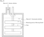
- the reaction is preferably performed by a method of adding a solution ⁇ obtained by dissolving a monoamine in the base oil (A) to a heated solution ⁇ obtained by dissolving an isocyanate compound in the base oil (A).
- a diisocyanate having a group corresponding to the divalent aromatic hydrocarbon group represented by R 3 in the general formula (b 1) is used as the isocyanate compound, and an amine having a group corresponding to the monovalent hydrocarbon group represented by R 1 and R 2 is used as the monoamine, whereby a desired urea-based thickener (B) can be synthesized according to the method.
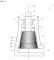
- Fig. 1 is a schematic cross-sectional view of the grease production apparatus in the above [1] that can be used in the embodiment of the present invention.
- a grease production apparatus 1 shown in Fig. 1 includes a container body 2 for introducing a grease raw material into the inside thereof, and a rotor 3 having a rotation axis 12 on a central axis line of an inner periphery of the container body 2 and rotating around the rotation axis 12 as a center axis.
- the rotor 3 rotates at a high speed around the rotation axis 12 as a center axis to impart a high shearing force to the grease raw material inside the container body 2. Accordingly, a grease containing the urea-based thickener (B) is produced.
- the container body 2 is preferably partitioned into an introduction portion 4, a retention portion 5, a first inner peripheral surface 6, a second inner peripheral surface 7, and a discharge portion 8 in this order from an upstream side.
- the container body 2 has an inner peripheral surface forming a truncated cone shape whose inner diameter gradually increases from the introduction portion 4 toward the discharge portion 8.
- the introduction portion 4 serving as one end of the container body 2 is provided with a plurality of solution introducing pipes 4A and 4B for introducing a grease raw material from the outside of the container body 2.
- the retention portion 5 is disposed downstream of the introduction portion 4, and is a space for temporarily retaining the grease raw material introduced from the introduction portion 4.
- the grease adhered to an inner peripheral surface of the retention portion 5 forms a large lump, so that it is preferred to transport the grease raw material to the first inner peripheral surface 6 in a downstream side in the shortest possible time. More preferably, it is preferred to transport the grease raw material directly to the first inner peripheral surface 6 without passing through the retention portion 5.
- the first inner peripheral surface 6 is disposed in a downstream portion adjacent to the retention portion 5, and the second inner peripheral surface 7 is disposed in a downstream portion adjacent to the first inner peripheral surface 6.
- the discharge portion 8 serving as the other end of the container body 2 is a portion for discharging the grease stirred by the first inner peripheral surface 6 and the second inner peripheral surface 7, and is provided with a discharge port 11 for discharging the grease.
- the discharge port 11 is formed in a direction orthogonal or approximately orthogonal to the rotation axis 12. Accordingly, the grease is discharged from the discharge port 11 to the direction orthogonal or approximately orthogonal to the rotation axis 12.
- the discharge port 11 does not necessarily have to be orthogonal to the rotation axis 12, and may be formed in a direction parallel or approximately parallel to the rotation axis 12.
- the rotor 3 is provided rotatably on a center axis line of the inner peripheral surface of the container body 2, which has a truncated cone shape, as the rotation axis 12, and rotates counterclockwise when the container body 2 is viewed from an upstream portion to a downstream portion as shown in Fig. 1 .
- the rotor 3 has an outer peripheral surface that expands in accordance with the enlargement of the inner diameter of the truncated cone of the container body 2, and the outer peripheral surface of the rotor 3 and the truncated cone-shaped inner peripheral surface of the container body 2 are maintained at a constant interval.
- the outer peripheral surface of the rotor 3 is provided with a first concave-convex portion 13 of the rotor in which concave and convex are alternately provided along a surface of the rotor 3.
- the first concave-convex portion 13 of the rotor is inclined to the rotation axis 12 of the rotor 3 in a direction from the introduction portion 4 to the discharge portion 8, and has a feeding ability in the direction from the introduction portion 4 to the discharge portion 8. That is, the first concave-convex portion 13 of the rotor is inclined in a direction in which a solution is pushed toward a downstream side when the rotor 3 rotates in the direction shown in Fig. 1 .
- a step difference between a concave portion 13A and a convex portion 13B in the first concave-convex portion 13 of the rotor is preferably 0.3 to 30, more preferably 0.5 to 15, and still more preferably 2 to 7, when a diameter of the concave portion 13A on the outer peripheral surface of the rotor 3 is 100.
- the number of convex portions 13B in the first concave-convex portion 13 of the rotor in a circumferential direction is preferably 2 to 1,000, more preferably 6 to 500, and still more preferably 12 to 200.
- a ratio of a width of the convex portion 13B to a width of the concave portion 13A in the first concave-convex portion 13 of the rotor [(width of convex portion)/(width of concave portion)] in a cross section orthogonal to the rotation axis 12 of the rotor 3 is preferably 0.01 to 100, more preferably 0.1 to 10, and still more preferably 0.5 to 2.
- An inclination angle of the first concave-convex portion 13 of the rotor to the rotation axis 12 is preferably 2° to 85°, more preferably 3° to 45°, and still more preferably 5° to 20°.
- the first inner peripheral surface 6 of the container body 2 is provided with the first concave-convex portion 9 formed with a plurality of concave and convex along the inner peripheral surface thereof.
- the concave and the convex of the first concave-convex portion 9 on a container body 2 side are inclined in a direction opposite to the first concave-convex portion 13 of the rotor.
- the plurality of concave and convex in the first concave-convex portion 9 on the container body 2 side are inclined in the direction in which the solution is pushed toward the downstream side when the rotation axis 12 of the rotor 3 rotates in the direction shown in Fig. 1 .
- a stirring ability and a discharge ability are further enhanced by the first concave-convex portion 9 having the plurality of concave and convex provided on the first inner peripheral surface 6 of the container body 2.
- a depth of the concave and the convex in the first concave-convex portion 9 on the container body 2 side is preferably 0.2 to 30, more preferably 0.5 to 15, and still more preferably 1 to 5, when the inner diameter (diameter) of the container is set to 100.
- the number of the concave and the convex in the first concave-convex portion 9 on the container body 2 side is preferably 2 to 1,000, more preferably 6 to 500, and still more preferably 12 to 200.
- a ratio of a width of a concave portion to a width of a convex portion between grooves in the concave and the convex in the first concave-convex portion 9 on the container body 2 side [(width of concave portion)/(width of convex portion)] is preferably 0.01 to 100, more preferably 0.1 to 10, and still more preferably 0.5 to 2 or less.
- An inclination angle of the concave and the convex in the first concave-convex portion 9 on the container body 2 side to the rotation axis 12 is preferably 2° to 85°, more preferably 3° to 45°, and still more preferably 5° to 20°.
- the first inner peripheral surface 6 can function as a shearing portion for imparting a high shearing force to the grease raw material or the grease, but the first concave-convex portion 9 does not necessarily have to be provided.
- a second concave-convex portion 14 of the rotor having concave and convex alternately provided along the surface of the rotor 3 is provided on an outer peripheral surface of a downstream portion of the first concave-convex portion 13 of the rotor.
- the second concave-convex portion 14 of the rotor is inclined to the rotation axis 12 of the rotor 3, and has a feeding restraining ability to push the solution back toward the upstream side from the introduction portion 4 toward the discharge portion 8.
- a step difference in the second concave-convex portion 14 of the rotor is preferably 0.3 to 30, more preferably 0.5 to 15, and still more preferably 2 to 7, when a diameter of the concave portion in the outer peripheral surface of the rotor 3 is set to 100.
- the number of convex portions in the second concave-convex portion 14 of the rotor in the circumferential direction is preferably 2 to 1,000, more preferably 6 to 500, and still more preferably 12 to 200.
- a ratio of a width of a convex portion to a width of a concave portion in the second concave-convex portion 14 of the rotor in a cross section orthogonal to the rotation axis of the rotor 3 [(width of the convex portion)/(width of the concave portion)] is preferably 0.01 to 100, more preferably 0.1 to 10, and still more preferably 0.5 to 2.
- An inclination angle of the second concave-convex portion 14 of the rotor to the rotation axis 12 is preferably 2° to 85°, more preferably 3° to 45°, and still more preferably 5° to 20°.
- the second inner peripheral surface 7 of the container body 2 is provided with the second concave-convex portion 10 formed with a plurality of concave and convex adjacent to a downstream portion of the concave and the convex in the first concave-convex portion 9 on the container body 2 side.
- the plurality of concave and convex are formed on the inner peripheral surface of the container body 2, and that the concave and the convex are inclined in a direction opposite to an inclination direction of the second concave-convex portion 14 of the rotor.
- the plurality of concave and convex in the second concave-convex portion 10 on the container body 2 side are inclined in a direction in which the solution is pushed back toward the upstream side when the rotation axis 12 of the rotor 3 rotates in the direction shown in Fig. 1 .
- a stirring ability is further enhanced by the concave and the convex in the second concave-convex portion 10 provided on the second inner peripheral surface 7 of the container body 2.
- the second inner peripheral surface 7 of the container body can function as a shearing portion for imparting a high shearing force to the grease raw material or the grease.
- a depth of the concave portion in the second concave-convex portion 10 on the container body 2 side is preferably 0.2 to 30, more preferably 0.5 to 15, and still more preferably 1 to 5, when the inner diameter (diameter) of the container body 2 is set to 100.
- the number of concave portions in the second concave-convex portion 10 on the container body 2 side is preferably 2 to 1,000, more preferably 6 to 500, and still more preferably 12 to 200.
- a ratio of a width of the convex portion to a width of the concave portion of the concave and the convex in the second concave-convex portion 10 on the container body 2 side in the cross section orthogonal to the rotation axis 12 of the rotor 3 [(width of convex portion)/(width of concave portion)] is preferably 0.01 to 100, more preferably 0.1 to 10, and still more preferably 0.5 to 2.
- An inclination angle of the second concave-convex portion 10 on the container body 2 side to the rotation axis 12 is preferably 2° to 85°, more preferably 3° to 45°, and still more preferably 5° to 20°.
- a ratio of a length of the first concave-convex portion 9 on the container body 2 side to a length of the second concave-convex portion 10 on the container body 2 side [(length of first concave-convex portion)/(length of second concave-convex portion)] is preferably 2/1 to 20/1.
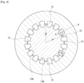
- Fig. 2 is a cross-sectional view in the direction orthogonal to the rotation axis 12 in the first concave-convex portion 9 on the container body 2 side of the grease production apparatus 1.
- a plurality of scrapers 15 each having a tip protruding toward an inner peripheral surface side of the container body 2 more than a tip in a protruding direction of the convex portion 13B in the first concave-convex portion 13 are provided.
- the second concave-convex portion 14 is also provided with a plurality of scrapers in which a tip of the convex portion protrudes toward the inner peripheral surface side of the container body 2, similar to the first concave-convex portion 13.
- the scraper 15 scrapes off the grease adhered to the inner peripheral surface of the first concave-convex portion 9 on the container body 2 side and the grease adhered to the second concave-convex portion 10 on the container body 2 side.
- a ratio [R2/R1] of a radius (R2) of the tip of the scraper 15 to a radius (R1) of the tip of the convex portion 13B is preferably more than 1.005 and less than 2.0.
- the number of scrapers 15 is preferably 2 to 500, more preferably 2 to 50, and still more preferably 2 to 10.
- the scraper 15 is provided in the grease production apparatus 1 shown in Fig. 2 , but may not be provided, or may be provided intermittently.
- the solution ⁇ and the solution ⁇ which are grease raw materials, are introduced respectively from the solution introducing pipes 4A and 4B in the introduction portion 4 of the container body 2, and the rotor 3 is rotated at a high speed, whereby a grease base material containing the urea-based thickener (B) can be produced.
- the urea-based thickener (B) in the grease composition can be miniaturized so as to satisfy the requirement (I) and further the requirement (II).
- a shear rate imparted to the grease raw material is preferably 10 2 s -1 or more, more preferably 10 3 s -1 or more, and still more preferably 10 4 s -1 or more, and the shear rate is typically 10 7 s -1 or less.
- a ratio of a maximum shear rate (Max) to a minimum shear rate (Min) in the shearing at high-speed rotation of the rotor 3 is preferably 100 or less, more preferably 50 or less, and still more preferably 10 or less.
- the urea-based thickener (B) or a precursor thereof in the grease composition is readily miniaturized, and a more uniform grease structure is provided.
- the maximum shear rate (Max) is the highest shear rate imparted to the mixed solution
- the minimum shear rate (Min) is the lowest shear rate applied to the mixed solution
- the gap A1 and the gap A2 are as shown in Fig. 2 .
- the grease production apparatus 1 When the grease production apparatus 1 is provided with the scraper 15, the grease adhered to the inner peripheral surface of the container body 2 can be scraped off, so that the generation of the lumps during kneading can be prevented, and a grease in which the urea-based thickener (B) is miniaturized can be continuously produced in a short time.
- the inner peripheral surface of the container body 2 has a truncated cone shape whose inner diameter increases from the introduction portion 4 toward the discharge portion 8, a centrifugal force has an effect of discharging the grease or the grease raw material in a downstream direction, and the rotation torque of the rotor 3 can be reduced to continuously produce the grease.
- the first concave-convex portion 13 of the rotor is provided on the outer peripheral surface of the rotor 3, the first concave-convex portion 13 of the rotor is inclined to the rotation axis 12 of the rotor 3, the first concave-convex portion 13 has a feeding ability from the introduction portion 4 to the discharge portion 8, the second concave-convex portion 14 of the rotor is inclined to the rotation axis 12 of the rotor 3, and the second concave-convex portion 14 has a feeding suppression ability from the introduction portion 4 toward the discharge portion 8, a high shear force can be imparted to the solution, and the urea-based thickener (B) in the grease composition can be miniaturized so as to satisfy the requirement (I) and further the requirement (II) even after being blended with an additive.
- the first concave-convex portion 9 is formed on the first inner peripheral surface 6 of the container body 2 and is inclined in the direction opposite to the first concave-convex portion 13 of the rotor, in addition to the effect of the first concave-convex portion 13 of the rotor, sufficient stirring for the grease raw material can be carried out while extruding the grease or the grease raw material in the downstream direction, and the urea-based thickener (B) in the grease composition can be miniaturized so as to satisfy the requirement (I) and further the requirement (II) even after being blended with an additive.
- the second concave-convex portion 10 is provided on the second inner peripheral surface 7 of the container body 2, and the second concave-convex portion 14 of the rotor is provided on the outer peripheral surface of the rotor 3, whereby the grease raw material can be prevented from flowing out from the first inner peripheral surface 6 of the container body more than necessary. Therefore, by imparting a high shear force to the solution to highly disperse the grease raw material, the urea-based thickener (B) can be miniaturized so as to satisfy the requirement (I) and further the requirement (II) even after being blended with an additive.
- the grease composition according to the embodiment of the present invention preferably further contains the sulfur-phosphorus-based extreme pressure agent (C) together with the component (A) and the component (B).
- the grease composition according to the present invention does not contain the sulfur-phosphorus-based extreme pressure agent (C)
- the base oil (A) by appropriately controlling the base oil (A), lubricating properties (that is, wear resistance, fatigue life, seizure resistance, and the like) of the grease composition can be maintained, and the lubricating life can be extended.
- the grease composition according to the embodiment of the present invention further contains the sulfur-phosphorus-based extreme pressure agent (C), the wear resistance, the fatigue life, and the seizure resistance can be further improved.
- C sulfur-phosphorus-based extreme pressure agent
- the sulfur-phosphorus-based extreme pressure agent (C) may be a mixture of a sulfur-based extreme pressure agent (C1) containing sulfur atoms and a phosphorous-based extreme pressure agent (C2) containing phosphorus atoms, or may be an extreme pressure agent (compound) (C3) containing sulfur atoms and phosphorus atoms. In addition, any one of these may be used, or a combination of these may be used, and it is preferred to use them in combination.
- the sulfur-based extreme pressure agent (C 1) means an extreme pressure agent containing sulfur atoms but not containing phosphorus atoms.
- the phosphorus-based extreme pressure agent (C2) means an extreme pressure agent containing phosphorus atoms but not containing sulfur atoms.
- examples of the sulfur-based extreme pressure agent (C 1) include a sulfurized fat and oil, a sulfurized fatty acid, a sulfurized ester, a sulfurized olefin, a monosulfide, a polysulfide, a dihydrocarbyl polysulfide, a thiadiazole compound, an alkyl thiocarbamoyl compound, a thiocarbamate compound, a dithiocarbamate compound, a thioterpene compound, and a dialkyl thiodipropionate compound. These may be used alone or may be used in combination of two or more thereof.
- a dithiocarbamate is preferred.
- examples of the phosphorus-based extreme pressure agent (C2) include: a phosphoric acid ester such as an aryl phosphate, an alkyl phosphate, an alkenyl phosphate, and an alkylaryl phosphate; an acidic phosphoric acid ester such as a monoaryl acid phosphate, a diaryl acid phosphate, a monoalkyl acid phosphate, a dialkyl acid phosphate, a monoalkenyl acid phosphate, and a dialkenyl aid phosphate; a phosphorous acid ester such as an aryl hydrogen phosphite, an alkyl hydrogen phosphite, an aryl phosphite, an alkyl phosphite, an alkenyl phosphite, and an arylalkyl
- a phosphoric acid ester amine salt is preferred.
- the sulfur-phosphorus-based extreme pressure agent (C) is the extreme pressure agent (compound) (C3) containing sulfur atoms and phosphorus atoms
- examples of the compound (C3) containing sulfur atoms and phosphorus atoms include a thiophosphorus acid such as triphenyl phosphorothioate, a monoalkyl thiophosphate, a dialkyl dithiophosphate, and a trialkyl trithiophosphate, and an amine salt thereof, and a zinc dialkyl dithiophosphate (Zn-DTP). These may be used alone or may be used in combination of two or more thereof.
- a thiophosphorus acid is preferred, and a triphenyl phosphorothioate is more preferred.
- a content of the sulfur-phosphorus-based extreme pressure agent (C) in the grease composition according to the embodiment of the present invention is preferably 0.1% by mass to 10% by mass, more preferably 0.5% by mass to 8.0% by mass, and still more preferably 1.0% by mass to 6.0% by mass, based on the total amount (100% by mass) of the grease composition, from the viewpoint of improving the fatigue life and the seizure resistance.
- the grease composition used in a reduction gear or a step-up gear is generally known to be blended with an organic molybdenum (C') as an extreme pressure agent in the grease composition from the viewpoint of improving the fatigue life and the seizure resistance.
- C' organic molybdenum
- the organic molybdenum (C') may also have drawbacks in corrosion resistance and compatibility with a seal rubber.
- the grease composition according to the embodiment of the present invention it is preferred to reduce a content of the organic molybdenum (C') from the viewpoint of further improving a torque transmitting efficiency and a leakage prevention performance.
- the content of the organic molybdenum (C') is preferably less than 1.0% by mass, more preferably less than 0.1% by mass, and still more preferably less than 0.01% by mass, based on the total amount (100% by mass) of the grease composition, and is most preferably free of the organic molybdenum (C').
- the grease composition according to the embodiment of the present invention may contain the additive (D) other than the component (B) and the component (C), which is blended in general greases, within a range in which the effects of the present invention are not impaired.
- Examples of the additive (D) include an antioxidant, a rust inhibitor, a dispersant, and a metal deactivator.
- the additive (D) may be used alone or may be used in combination of two or more thereof.
- antioxidants examples include an amine-based antioxidant such as a diphenylamine-based compound and a naphthylamine-based compound, and a phenol-based antioxidant such as a monocyclic phenol-based compound and a polycyclic phenol-based compound.
- rust inhibitor examples include a carboxylic acid-based rust inhibitor such as an alkenyl succinic acid polyhydric alcohol ester, zinc stearate, thiadiazole and a derivative thereof, and benzotriazole and a derivative thereof.
- carboxylic acid-based rust inhibitor such as an alkenyl succinic acid polyhydric alcohol ester, zinc stearate, thiadiazole and a derivative thereof, and benzotriazole and a derivative thereof.
- dispersant examples include an ash-free dispersant such as succinimide and a boron-based succinimide.
- Examples of the metal deactivator include a benzotriazole-based compound.
- contents of the additive (D) are each independently typically 0.01% by mass to 20% by mass, preferably 0.01% by mass to 15% by mass, more preferably 0.01% by mass to 10% by mass, and still more preferably 0.01% by mass to 7% by mass, based on the total amount (100% by mass) of the grease composition.
- a worked penetration at 25°C of the grease composition according to the embodiment of the present invention is preferably 240 to 450, more preferably 260 to 450, still more preferably 300 to 450, yet still more preferably 340 to 450, even more preferably 355 to 450, further more preferably 355 to 430, and yet further more preferably 380 to 430.
- the leakage prevention performance of the grease composition is excellent, and a grease composition excellent in torque transmitting efficiency and leakage prevention performance is provided.
- the worked penetration of the grease composition means a value measured at 25°C in conformity with JIS K2220:2013.
- An apparent viscosity of the grease composition according to the embodiment of the present invention is preferably 10 to 50, more preferably 11 to 45, still more preferably 12 to 40, yet still more preferably 13 to 35, and even still more preferably 15 to 30.
- the apparent viscosity of the grease composition means a value measured at -10°C and a shear rate of 10 s -1 in conformity with JIS K2220:2013.
- a dropping point of the grease composition according to the embodiment of the present invention is preferably 160 or more, more preferably 170 or more, still more preferably 180 or more, yet still more preferably 200 or more, and even still more preferably 210 or more.
- the dropping point of the grease composition according to the embodiment of the present invention is preferably 300 or less.
- the dropping point of the grease composition means a value measured in conformity with JIS K2220:2013.
- An oil separation degree of the grease composition according to the embodiment of the present invention is preferably 1 to 25, more preferably 1.5 to 20, still more preferably 2 to 17, yet still more preferably 2.5 to 15, and even still more preferably 3 to 10.
- the oil separation degree of the grease composition means a value measured under conditions of a temperature of 100°C and a time of 24 hours in conformity with JIS K2220:2013.
- a starting torque at a low temperature of the grease composition according to the embodiment of the present invention is preferably 20 or less, more preferably 19 or less, still more preferably 16 or less, and yet still more preferably 14 or less.
- a rotational torque at a low temperature of the grease composition according to the embodiment of the present invention is preferably 6 or less, more preferably 5 or less, and still more preferably 4 or less.
- a low-temperature torque of the grease composition means a starting torque (unit: N ⁇ m) and a rotational torque (unit: N ⁇ m) obtained at a temperature of - 10°C in conformity with JIS K2220:2013.
- the starting torque is a torque required to output a power from a stationary state, and is preferably small.
- the rotational torque is a torque required to unintermittently continuously output a power, and is preferably small.
- a lubricating life of the grease composition measured and calculated by a method described in Examples to be described later is preferably more than 280 hours, more preferably 300 hours or longer, still more preferably 350 hours or longer, and yet still more preferably 400 hours or longer.
- a state of a component after the lubricating life is measured and calculated by the method described in Examples to be described later, a state in which the component is not damaged is preferred, and a state in which a wear amount of the component is small is more preferred.
- the grease composition according to the present invention can be produced by mixing a grease (base grease) containing the base oil (A) and the urea-based thickener (B) as synthetized by the method, with one or more selected from the sulfur-phosphorus-based extreme pressure agent (C) and the additive (D) as necessary.
- base grease containing the base oil (A) and the urea-based thickener (B) as synthetized by the method, with one or more selected from the sulfur-phosphorus-based extreme pressure agent (C) and the additive (D) as necessary.
- the grease composition according to the present invention can be produced by blending one or more selected from the sulfur-phosphorus-based extreme pressure agent (C) and the additive (D) in the grease (base grease), followed by stirring, or blending one or more selected from the sulfur-phosphorus-based extreme pressure agent (C) and the additive (D) in the grease (base grease) while stirring the grease.
- the grease composition according to the present invention can achieve both the low temperature characteristics and the lubricating life.
- the grease composition according to the embodiment of the present invention can be used for lubricating portions to be lubricated, such as a bearing portion, a sliding portion, a gear portion, and a joint portion, in an apparatus required to have such characteristics. More specifically, it is preferred to use the grease composition in a bearing portion of a hub unit, an electric power steering, a driving electric motor flywheel, a ball joint, a wheel bearing, a spline portion, a constant velocity joint, a clutch booster, a servo motor, a blade bearing, or a generator.
- Examples of the field of the apparatus for which the grease composition according to the present invention can be suitably used include the automobile field, the office equipment field, the machine-tool field, the windmill field, the construction field, the agricultural machine field, or the industrial robot field.
- Examples of the portion to be lubricated in the apparatus for the automobile field, in which the grease composition according to the present invention can be suitably used include: bearing portions in an apparatus, such as a radiator fan motor, a fan coupling, an alternator, an idler pulley, a hub unit, a water pump, a power window, a wiper, an electric power steering, a driving electric motor fly wheel, a ball joint, a wheel bearing, a spline portion, and a constant velocity joint; and bearing portions, gear portions, and sliding portions in an apparatus such as a door lock, a door hinge, and a clutch booster.
- Examples of the portion to be lubricated in the apparatus for the office equipment field, in which the grease composition according to the present invention can be suitably used, include a fixing roll in an apparatus such as a printer, and bearing and gear portions in an apparatus such as a polygon motor.
- Examples of the portion to be lubricated in the apparatus for the machine-tool field, in which the grease composition according to the present invention can be suitably used, include bearing portions in a reduction gear, such as a spindle, a servo motor, and a working robot.
- Examples of the portion to be lubricated in the apparatus for the windmill field, in which the grease composition according to the present invention can be suitably used include a blade bearing and bearing portions in a generator.
- Examples of the portion to be lubricated in the apparatus for the construction or agricultural machine field, in which the grease composition according to the present invention can be suitably used include bearing portions, gear portions, and sliding portions, such as a ball joint and a spline portion.
- the grease composition according to the present invention can be suitably used for a reduction gear provided in an industrial robot and a step-up gear provided in a wind turbine generator system.
- Examples of the reduction gear and the step-up gear include a reduction gear composed of a gear mechanism and a step-up gear composed of a gear mechanism.
- an application object of the grease composition according to the embodiment of the present invention is not limited to the reduction gear composed of a gear mechanism and the step-up gear composed of a gear mechanism.
- the grease composition according to the embodiment of the present invention can also be applied to a traction drive or the like.
- examples of the reduction gear include an RV type, a harmonic type, and a cyclo type, any of which can be suitably used.
- an apparatus having the grease composition according to the present invention in a lubricating site, such as a bearing portion, a sliding portion, a gear portion, and a joint portion, preferably a reduction gear or a step-up gear.
- a lubricating method for lubricating a lubricating site in an apparatus such as a reduction gear and a step-up gear (for example, a bearing portion, a sliding portion, a gear portion, and a joint portion) with the grease composition according to the present invention.
- the measurement was performed at 25°C in conformity with JIS K2220:2013.
- the apparent viscosity was determined at -10°C and a shear rate of 10 s -1 in conformity with JIS K2220:2013.
- the measurement was performed in conformity with JIS K2220:2013.
- the measurement was performed under conditions of a temperature of 100°C and a time of 24 hours in conformity with JIS K2220:2013.
- the base oil (A) used in Examples 1 to 3 and Comparative Example 1 was prepared by blending and mixing the following base oil (A1), base oil (A2), and base oil (A3) in amounts shown in Table 1.
- Predetermined amounts of an antioxidant, a rust inhibitor, and a metal deactivator were used.
- a separately prepared base oil (A) obtained by mixing 10.0 parts by mass of the high-viscosity base oil (A1), 30.0 parts by mass of the low-viscosity base oil (A2), and 2.5 parts by mass of the ultra-high viscosity hydrocarbon-based synthetic oil (A3) and heating the mixture to 70°C 1.03 parts by mass of octadecylamine and 1.52 parts by mass of cyclohexylamine were added to prepare a solution ⁇ .
- the solution ⁇ heated to 70°C was introduced at a flow rate of 150 L/h from the solution introducing pipe 4A into the container body 2, and the solution ⁇ heated to 70°C was simultaneously introduced at a flow rate of 150 L/h from the solution introducing pipe 4B into the container body 2, and the solution ⁇ and the solution ⁇ were unintermittently continuously introduced into the container body 2 in a state where the rotor 3 was rotated, thereby synthesizing a urea grease (b 1).
- the rotation speed of the rotor 3 of the grease production apparatus 1 used was 8,000 rpm.
- a maximum shear rate (Max) was 10,500 s -1 , and stirring was performed while setting a ratio of the maximum shear rate (Max) to the minimum shear rate (Min) [Max/Min] to 3.5.
- the urea-based thickener (B1) contained in the urea grease (b1) corresponds to a compound represented by the general formula (b1) in which R 1 and R 2 are selected from a cyclohexyl group and an octadecyl group and R 3 is a diphenylmethylene group.
- a molar ratio of octadecylamine to cyclohexylamine used as the raw materials is 20/80.
- the urea grease (b1) discharged from the grease production apparatus 1 shown in Fig. 1 was stirred and then cooled by natural cooling, and were then added with the sulfur-based extreme pressure agent (C1), the phosphorus-based extreme pressure agent (C2), the extreme pressure agent (C3) containing sulfur atoms and phosphorus atoms, and the additive (D) in blending amounts shown in Table 1, to obtain a grease composition in Example 1.
- Grease compositions in Examples 2 and 3 were obtained by the same method as that of the grease composition in Example 1, except that urea-based thickeners (B2) and (B3) were used in which the blending of the base oil (A) was changed to the blending shown in Table 1 and production conditions of the urea grease were further adjusted to adjust the arithmetic average particle diameter and the specific surface area of particles containing the urea-based thickener (B) to be described later to values shown in Table 1.
- the urea-based thickeners (B2) and (B3) correspond to a compound represented by the general formula (b1) in which R 1 and R 2 are selected from a cyclohexyl group and an octadecyl group and R 3 is a diphenylmethylene group.
- a molar ratio of octadecylamine and cyclohexylamine used as the raw materials is 20/80.
- a base oil (A) obtained by mixing 10.0 parts by mass of the high-viscosity base oil (A1), 30.0 parts by mass of the low-viscosity base oil (A2), and 2.5 parts by mass of the ultra-high viscosity hydrocarbon-based synthetic oil (A3) 2.46 parts by mass of diphenylmethane-4,4'-diisocyanate was added to prepare a solution ⁇ .
- a separately prepared base oil (A) obtained by mixing 10.0 parts by mass of the high-viscosity base oil (A1), 30.0 parts by mass of the low-viscosity base oil (A2), and 2.5 parts by mass of the ultra-high viscosity hydrocarbon-based synthetic oil (A3) 1.03 parts by mass of octadecylamine and 1.52 parts by mass of cyclohexylamine were added to prepare a solution ⁇ .
- the solution ⁇ heated to 70°C was introduced at a flow rate of 504 L/h from a solution introducing pipe into a container body. Thereafter, the solution ⁇ heated to 70°C was introduced at a flow rate of 144 L/h from the solution introducing pipe into the container body having the solution ⁇ charged therein. After introducing all the solution ⁇ into the container body, a stirring blade was rotated, and the temperature was raised to 160°C while continuing the stirring, followed by holding for 1 hour to synthesize a urea grease (b4).
- a maximum shear rate (Max) was 42,000 s -1 , and stirring was performed while setting a ratio of the maximum shear rate (Max) to a minimum shear rate (Min) [Max/Min] to 1.03.
- a urea-based thickener (B4) contained in the urea grease (b4) corresponds to a compound represented by the general formula (b1) in which R 1 and R 2 are selected from a cyclohexyl group and an octadecyl group and R 3 is a diphenylmethylene group.
- a molar ratio of octadecylamine and cyclohexylamine used as the raw materials is 20/80.
- the urea grease (b4) discharged from the grease production apparatus 1 shown in Fig. 3 was stirred and then cooled by natural cooling, and were then added with the sulfur-based extreme pressure agent (C1), the phosphorus-based extreme pressure agent (C2), the extreme pressure agent (C3) containing sulfur atoms and phosphorus atoms, and the additive (D) in blending amounts shown in Table 1, to obtain a grease composition in Comparative Example 1.
- a particle diameter of the particles containing the urea-based thickener in the grease composition was evaluated. Specifically, the urea greases as synthesized in Examples 1 to 3 and Comparative Example 1 were each used as a measurement sample and determined for the particle diameter of the particles, including the particle diameter of the particles containing the urea-based thickener (B), by the following procedures.
- the measurement sample was defoamed in vacuum and then filled in a 1-mL syringe, 0.10 mL to 0.15 mL of the sample was extruded from the syringe, and the extruded sample was placed on a surface of a platy cell of a fixture for paste cell. Then, another platy cell was superimposed on the sample, thereby obtaining a measurement cell having the sample sandwiched by the two cells. Then, using a laser diffraction type particle diameter analyzer (trade name: LA-920 manufactured by Horiba, Ltd.), an arithmetic average particle diameter on an area basis of the particles in the sample of the measurement cell was measured.
- a laser diffraction type particle diameter analyzer trade name: LA-920 manufactured by Horiba, Ltd.
- the "arithmetic average particle diameter on an area basis” means a value obtained by arithmetically averaging a particle diameter distribution on an area basis.
- the particle diameter distribution on an area basis is one expressing a frequency distribution of particle diameters in all particles as measurement targets on the basis of an area calculated based on the particle diameter (in detail, a cross-sectional area of particles having the particle diameter).
- J means a division number of particle diameter
- q(J) means a frequency distribution value (unit: %)
- X(J) means a representative diameter (unit: pm) in a range of a J-th particle diameter.
- the specific surface area was calculated using the particle diameter distribution of the particles containing the thickener in the grease composition as measured in the section of Requirement (I). Specifically, using the particle diameter distribution, the total of surface areas (unit: cm 2 ) of particles per unit volume (1 cm 3 ) was calculated, and was designated as the specific surface area (unit: cm 2 /cm 3 ).
- a starting torque (unit: N ⁇ m) and a rotational torque (unit: N ⁇ m) at a low temperature (-10°C) were determined in conformity with JIS K2220:2013.
- the starting torque is a torque required to output a power from a stationary state, and is preferably small.
- the rotational torque is a torque required to unintermittently continuously output a power, and is preferably small
- Table 1 Component (unit) Example Comparative Example 1 2 3 1 Grease composition Base oil (A) High-viscosity base oil (A1) % by mass 20.0 10.0 30.0 20.0 Low-viscosity base oil (A2) % by mass 60.0 73.0 45.0 60.0 Ultra-high viscosity synthetic oil (A3) % by mass 5.0 2.0 10.0 5.0 Urea-based thickener (B) Urea-based thickener (B1) % by mass 5.0 - - - Urea-based thickener (B2) % by mass - 5.0 - - Urea-based thickener (B3) % by mass - - 5.0 - Urea-based thickener (B4) % by mass - - - 5.0 Extreme pressure agent(C) Sulfur-based extreme pressure agent (C1) % by mass 4.0 4.0 4.0 4.0 4.0 Phosphorus-based extreme pressure agent (C2) % by mass 1.0 1.0 1.0 1.0 Extreme
- both the starting torque and the rotational torque are sufficiently smaller than those of Comparative Example 1, and thus the low-temperature characteristics are excellent.
- a grease containing a lithium soap (B'1) and an organic molybdenum (C') with blending shown in Table 2 was used as a grease composition in Comparative Example 2.
- a grease containing a lithium soap (B'2) and the organic molybdenum (C') with blending shown in Table 2 was used as a grease composition in Comparative Example 3.
- Fig. 4 is a diagrammatic view of an apparatus used when measuring a lubricating life of the grease composition in Examples 1 and 2 and Comparative Examples 2 and 3.
- a measurement apparatus 100 shown in Fig. 4 is one in which an input side motor part 111, an input side torque measuring unit 112, a test reduction gear 113 (trade name: "RV-42N” manufactured by Nabtesco Corporation), an output side torque measuring unit 122, a step-up gear 123 (trade name: "RV-125V” manufactured by Nabtesco Corporation) for absorbing a power, and a motor part 121 are connected in this order.
- a grease filling case of the test reduction gear 113 of the measurement apparatus 100 shown in Fig. 4 was filled with 200 mL of the grease composition.
- the measurement apparatus 100 was actuated under conditions of a load torque of 1,030 N ⁇ m, an input rotation speed of the test reduction gear 113 of 2,150 rpm, and an output rotation speed of the test reduction gear 113 of 15 rpm, and an input side torque (unit: N ⁇ m) and an output side torque (unit: N ⁇ m) were measured.
- a speed reduction ratio of the test reduction gear 113 to the step-up gear 123 is about 140.
- the test reduction gear 113 has a rated load torque of 412 N ⁇ m and a rated life of 280 hours. In this evaluation, a torque 2.5 times the rated torque was applied to accelerate the test, and a target life was set to 1.5 times the rated life.
- the masses of the rolling element and the roller bearing actuated by being filled with the grease composition in Example 1 were set to 100.00, and relative masses of the rolling element and the roller bearing actuated by being filled with the grease composition in Example 2 and Comparative Examples 2 and 3 were calculated. In addition, it was visually checked how much a disassembled conical roller bearing was damaged on the entire surface of the tested component.
- Examples 1 and 2 have a lubricating life 1.5 times or more the rated life.
Landscapes
- Chemical & Material Sciences (AREA)
- Oil, Petroleum & Natural Gas (AREA)
- Chemical Kinetics & Catalysis (AREA)
- General Chemical & Material Sciences (AREA)
- Organic Chemistry (AREA)
- Engineering & Computer Science (AREA)
- Lubricants (AREA)
Claims (14)
- Schmierfettzusammensetzung umfassend:ein Basisöl (A); undein Verdickungsmittel auf Harnstoffbasis (B), wobeiTeilchen enthaltend das Verdickungsmittel auf Harnstoffbasis (B) in der Schmierfettzusammensetzung die folgende Anforderung (I) erfüllen:·Anforderung (I): ein arithmetischer durchschnittlicher Teilchendurchmesser der Teilchen auf Flächenbasis, gemessen durch ein Laserbeugungs- und Streuungsverfahren, beträgt 2,0 µm oder weniger,das Basisöl (A) ein gemischtes Basisöl ist, enthaltend ein hochviskoses Basisöl (A1) mit einer kinematischen Viskosität bei 40°C von 250 mm2/s bis 550 mm2/s, ein niedrigviskoses Basisöl (A2) mit einer kinematischen Viskosität bei 40°C von 5,0 mm2/s bis 110 mm2/s, und ein ultrahochviskoses synthetisches Öl auf Kohlenwasserstoffbasis (A3) mit einem zahlenmittleren Molekulargewicht (Mn) von 2.500 bis 4.500 und einer kinematischen Viskosität bei 40°C von 25.000 mm2/s bis 50.000 mm2/s,das Basisöl (A) eine kinematische Viskosität bei 40°C von 25 mm2/s bis 105 mm2/s aufweist unddas Basisöl (A) einen Viskositätsindex von 120 oder mehr hat.
- Schmierfettzusammensetzung gemäß Anspruch 1, wobei die Teilchen enthaltend das Verdickungsmittel auf Harnstoffbasis (B) in der Schmierfettzusammensetzung ferner die folgende Anforderung (II) erfüllen:·Anforderung (II): eine spezifische Oberfläche der Teilchen, gemessen durch das Laserbeugungs- und Streuungsverfahren, beträgt 0,5 × 105 cm2/cm3 oder mehr.
- Schmierfettzusammensetzung gemäß Anspruch 1 oder 2, wobeibezogen auf eine Gesamtmenge der Schmierfettzusammensetzung,der Gehalt an hochviskosem Basisöl (A1) 10 Masse-% bis 40 Masse-% beträgt,der Gehalt an niedrigviskosem Basisöl (A2) 40 Masse-% bis 87 Masse-% beträgt, undder Gehalt des ultrahochviskosen synthetischen Öls auf Kohlenwasserstoffbasis (A3) 2 Masse-% bis 10 Masse-% beträgt.
- Schmierfettzusammensetzung gemäß mindestens einem der Ansprüche 1 bis 3, wobei das Gehaltsverhältnis [(A2)/(A1)] des niedrigviskosen Basisöls (A2) zu dem hochviskosen Basisöl (A1) 1,0 bis 8,7, bezogen auf das Massenverhältnis, beträgt.
- Schmierfettzusammensetzung gemäß mindestens einem der Ansprüche 1 bis 4, wobei das Gehaltsverhältnis [(A2)/(A3)] des niedrigviskosen Basisöls (A2) zu dem ultrahochviskosen synthetischen Öl auf Kohlenwasserstoffbasis (A3) 4,0 bis 43,5, bezogen auf das Massenverhältnis, beträgt.
- Schmierfettzusammensetzung gemäß mindestens einem der Ansprüche 1 bis 5, wobei das Gehaltsverhältnis [(A1)/(A3)] des hochviskosen Basisöls (A1) zu dem ultrahochviskosen synthetischen Öl auf Kohlenwasserstoffbasis (A3) 1,0 bis 20,0, bezogen auf das Massenverhältnis, beträgt.
- Schmierfettzusammensetzung gemäß mindestens einem der Ansprüche 1 bis 6, ferner umfassend:
ein Extremdruckmittel auf Schwefel-Phosphor-Basis (C). - Schmierfettzusammensetzung gemäß Anspruch 7, wobei das Extremdruckmittel auf Schwefel-Phosphor-Basis (C) enthält eine Mischung aus einem Extremdruckmittel auf Schwefel-Basis (C1) enthaltend Schwefelatome und einem Extremdruckmittel auf Phosphor-Basis (C2) enthaltend Phosphoratome.
- Schmierfettzusammensetzung gemäß mindestens einem der Ansprüche 1 bis 8, wobei der Gehalt des Verdickungsmittels auf Harnstoffbasis (B) 1,0 Masse-% bis 15,0 Masse-%, bezogen auf die Gesamtmenge der Schmierfettzusammensetzung, beträgt.
- Schmierfettzusammensetzung gemäß mindestens einem der Ansprüche 1 bis 9, wobei die Walkpenetration (worked penetration) bei 25°C 355 bis 430 beträgt.
- Schmierfettzusammensetzung gemäß mindestens einem der Ansprüche 1 bis 10, wobei das Verdickungsmittel auf Harnstoffbasis (B) eines oder mehrere ist, ausgewählt aus Diharnstoffverbindungen der folgenden allgemeinen Formel (b1) :
R1-NHCONH-R3-NHCONH-R2 (b1)
worin R1 und R2 jeweils unabhängig voneinander darstellen eine einwertige Kohlenwasserstoffgruppe mit 6 bis 24 Kohlenstoffatomen, wobei R1 und R2 gleich oder verschieden voneinander sein können, und R3 eine zweiwertige aromatische Kohlenwasserstoffgruppe mit 6 bis 18 Kohlenstoffatomen darstellt. - Schmierfettzusammensetzung gemäß mindestens einem der Ansprüche 1 bis 11, ferner umfassend:
ein oder mehrere Additive (D), ausgewählt aus einem Antioxidationsmittel, einem Schmierfähigkeitsverbesserer, einem Rostinhibitor, einem Dispersionsmittel und einem Metalldeaktivator. - Schmierfettzusammensetzung gemäß mindestens einem der Ansprüche 1 bis 12, die zur Schmierung einer Schmierstelle in einem Untersetzungsgetriebe oder einem Übersetzungsgetriebe verwendet wird.
- Verfahren zum Schmieren, umfassend:
Schmieren einer Schmierstelle in einem Untersetzungsgetriebe oder einem Übersetzungsgetriebe mit der Schmierfettzusammensetzung gemäß mindestens einem der Ansprüche 1 bis 12.
Applications Claiming Priority (2)
| Application Number | Priority Date | Filing Date | Title |
|---|---|---|---|
| JP2020065440A JP7341940B2 (ja) | 2020-03-31 | 2020-03-31 | グリース組成物 |
| PCT/JP2021/010632 WO2021200120A1 (ja) | 2020-03-31 | 2021-03-16 | グリース組成物 |
Publications (3)
| Publication Number | Publication Date |
|---|---|
| EP4130210A1 EP4130210A1 (de) | 2023-02-08 |
| EP4130210A4 EP4130210A4 (de) | 2024-04-10 |
| EP4130210B1 true EP4130210B1 (de) | 2025-01-22 |
Family
ID=77929484
Family Applications (1)
| Application Number | Title | Priority Date | Filing Date |
|---|---|---|---|
| EP21780915.1A Active EP4130210B1 (de) | 2020-03-31 | 2021-03-16 | Schmierfettzusammensetzung |
Country Status (5)
| Country | Link |
|---|---|
| US (1) | US12043816B2 (de) |
| EP (1) | EP4130210B1 (de) |
| JP (1) | JP7341940B2 (de) |
| CN (1) | CN115279875B (de) |
| WO (1) | WO2021200120A1 (de) |
Families Citing this family (4)
| Publication number | Priority date | Publication date | Assignee | Title |
|---|---|---|---|---|
| JP7455376B2 (ja) * | 2020-06-29 | 2024-03-26 | 株式会社ニッペコ | グリース組成物 |
| EP4317382B1 (de) * | 2021-03-31 | 2025-08-13 | Idemitsu Kosan Co., Ltd. | Schmierfettzusammensetzung |
| JP2023151683A (ja) * | 2022-03-31 | 2023-10-16 | 出光興産株式会社 | 潤滑剤組成物及びその製造方法 |
| JPWO2024150774A1 (de) * | 2023-01-12 | 2024-07-18 |
Family Cites Families (23)
| Publication number | Priority date | Publication date | Assignee | Title |
|---|---|---|---|---|
| US20040198617A1 (en) | 2001-07-09 | 2004-10-07 | Hirotsugu Kinoshita | Lubricant composition for ball joint and ball joint |
| JP2008115304A (ja) * | 2006-11-06 | 2008-05-22 | Cosmo Sekiyu Lubricants Kk | 樹脂用ウレアグリース組成物 |
| US20100105585A1 (en) * | 2008-10-28 | 2010-04-29 | Carey James T | Low sulfur and ashless formulations for high performance industrial oils |
| JP2010248422A (ja) | 2009-04-17 | 2010-11-04 | Bridgestone Corp | ゴム組成物及びそれを用いたタイヤ |
| JP5444806B2 (ja) | 2009-04-20 | 2014-03-19 | 協同油脂株式会社 | グリース組成物及び機械部品 |
| JP2011042747A (ja) | 2009-08-21 | 2011-03-03 | Kyodo Yushi Co Ltd | 減速機用グリース組成物及び減速機 |
| EP2554644A4 (de) | 2010-03-26 | 2013-12-04 | Idemitsu Kosan Co | Schmierfettzusammensetzung |
| SG11201400980UA (en) * | 2011-09-27 | 2014-07-30 | Jx Nippon Oil & Energy Corp | System-oil composition for crosshead diesel engine |
| WO2013128748A1 (ja) * | 2012-02-28 | 2013-09-06 | Jx日鉱日石エネルギー株式会社 | 潤滑油組成物 |
| KR101438916B1 (ko) * | 2012-11-02 | 2014-09-11 | 현대자동차주식회사 | 저온에서 윤활 성능이 우수한 그리이스 조성물 |
| JP2015064065A (ja) * | 2013-09-25 | 2015-04-09 | 株式会社ニッセイ | 減速機におけるグリース注入方法 |
| JP6326340B2 (ja) * | 2014-09-26 | 2018-05-16 | 三井化学株式会社 | グリース組成物 |
| CN107207993B (zh) | 2015-02-05 | 2020-05-19 | 出光兴产株式会社 | 润滑脂和润滑脂的制造方法 |
| JP6691679B2 (ja) | 2015-04-15 | 2020-05-13 | 株式会社ジェイテクト | グリース組成物および当該グリース組成物が封入された転がり軸受 |
| WO2017126703A1 (ja) * | 2016-01-22 | 2017-07-27 | Jxエネルギー株式会社 | 樹脂用潤滑剤組成物及び樹脂の潤滑方法 |
| JP6703849B2 (ja) | 2016-02-15 | 2020-06-03 | 協同油脂株式会社 | プロペラシャフトスプライン用グリース組成物およびプロペラシャフトスプライン |
| JP6702761B2 (ja) | 2016-02-26 | 2020-06-03 | 協同油脂株式会社 | ボールジョイント用グリース組成物 |
| WO2018043744A1 (ja) * | 2016-09-05 | 2018-03-08 | 出光興産株式会社 | グリース |
| JP2018039943A (ja) * | 2016-09-09 | 2018-03-15 | 昭和シェル石油株式会社 | 自動変速機用潤滑油組成物 |
| JP6797033B2 (ja) * | 2017-01-16 | 2020-12-09 | コスモ石油ルブリカンツ株式会社 | ウレア系グリース組成物 |
| JP2018188541A (ja) * | 2017-05-01 | 2018-11-29 | 出光興産株式会社 | グリース組成物 |
| CN110892047A (zh) * | 2017-08-31 | 2020-03-17 | 出光兴产株式会社 | 润滑脂组合物 |
| WO2020179589A1 (ja) | 2019-03-05 | 2020-09-10 | 出光興産株式会社 | グリース組成物、該グリース組成物を用いた摺動機構の潤滑方法及び装置 |
-
2020
- 2020-03-31 JP JP2020065440A patent/JP7341940B2/ja active Active
-
2021
- 2021-03-16 CN CN202180024775.0A patent/CN115279875B/zh active Active
- 2021-03-16 EP EP21780915.1A patent/EP4130210B1/de active Active
- 2021-03-16 WO PCT/JP2021/010632 patent/WO2021200120A1/ja not_active Ceased
- 2021-03-16 US US17/995,061 patent/US12043816B2/en active Active
Also Published As
| Publication number | Publication date |
|---|---|
| EP4130210A4 (de) | 2024-04-10 |
| JP7341940B2 (ja) | 2023-09-11 |
| JP2021161297A (ja) | 2021-10-11 |
| US20230128223A1 (en) | 2023-04-27 |
| WO2021200120A1 (ja) | 2021-10-07 |
| CN115279875A (zh) | 2022-11-01 |
| CN115279875B (zh) | 2024-01-12 |
| EP4130210A1 (de) | 2023-02-08 |
| US12043816B2 (en) | 2024-07-23 |
Similar Documents
| Publication | Publication Date | Title |
|---|---|---|
| EP3936591B1 (de) | Schmierfettzusammensetzung | |
| EP4130210B1 (de) | Schmierfettzusammensetzung | |
| EP3936592B1 (de) | Schmierfettzusammensetzung | |
| EP3936590B1 (de) | Schmierfettzusammensetzung sowie schmierverfahren und -vorrichtung für gleitmechanismus unter verwendung dieser schmierfettzusammensetzung | |
| EP3851506B1 (de) | Schmiermittelzusammensetzung und gleichlaufgelenk | |
| EP3919592B1 (de) | Verfahren zum schmieren mit einer schmierfettzusammensetzung | |
| EP3677661A1 (de) | Schmierfettzusammensetzung | |
| EP4317381B1 (de) | Schmierfettzusammensetzung | |
| EP4365269A1 (de) | Schmierfettzusammensetzung | |
| EP4650419A1 (de) | Schmierfettzusammensetzung | |
| JP2025123101A (ja) | グリース組成物、グリース組成物の製造方法、及び車軸の潤滑方法 |
Legal Events
| Date | Code | Title | Description |
|---|---|---|---|
| STAA | Information on the status of an ep patent application or granted ep patent |
Free format text: STATUS: THE INTERNATIONAL PUBLICATION HAS BEEN MADE |
|
| PUAI | Public reference made under article 153(3) epc to a published international application that has entered the european phase |
Free format text: ORIGINAL CODE: 0009012 |
|
| STAA | Information on the status of an ep patent application or granted ep patent |
Free format text: STATUS: REQUEST FOR EXAMINATION WAS MADE |
|
| 17P | Request for examination filed |
Effective date: 20220929 |
|
| AK | Designated contracting states |
Kind code of ref document: A1 Designated state(s): AL AT BE BG CH CY CZ DE DK EE ES FI FR GB GR HR HU IE IS IT LI LT LU LV MC MK MT NL NO PL PT RO RS SE SI SK SM TR |
|
| DAV | Request for validation of the european patent (deleted) | ||
| DAX | Request for extension of the european patent (deleted) | ||
| A4 | Supplementary search report drawn up and despatched |
Effective date: 20240311 |
|
| RIC1 | Information provided on ipc code assigned before grant |
Ipc: C10M 115/08 20060101ALI20240304BHEP Ipc: C10M 107/02 20060101ALI20240304BHEP Ipc: C10N 50/10 20060101ALI20240304BHEP Ipc: C10N 40/04 20060101ALI20240304BHEP Ipc: C10N 40/02 20060101ALI20240304BHEP Ipc: C10N 30/06 20060101ALI20240304BHEP Ipc: C10N 30/02 20060101ALI20240304BHEP Ipc: C10N 30/00 20060101ALI20240304BHEP Ipc: C10N 20/06 20060101ALI20240304BHEP Ipc: C10N 20/04 20060101ALI20240304BHEP Ipc: C10N 20/02 20060101ALI20240304BHEP Ipc: C10N 20/00 20060101ALI20240304BHEP Ipc: C10M 169/02 20060101AFI20240304BHEP |
|
| GRAP | Despatch of communication of intention to grant a patent |
Free format text: ORIGINAL CODE: EPIDOSNIGR1 |
|
| STAA | Information on the status of an ep patent application or granted ep patent |
Free format text: STATUS: GRANT OF PATENT IS INTENDED |
|
| INTG | Intention to grant announced |
Effective date: 20240916 |
|
| GRAS | Grant fee paid |
Free format text: ORIGINAL CODE: EPIDOSNIGR3 |
|
| GRAA | (expected) grant |
Free format text: ORIGINAL CODE: 0009210 |
|
| STAA | Information on the status of an ep patent application or granted ep patent |
Free format text: STATUS: THE PATENT HAS BEEN GRANTED |
|
| AK | Designated contracting states |
Kind code of ref document: B1 Designated state(s): AL AT BE BG CH CY CZ DE DK EE ES FI FR GB GR HR HU IE IS IT LI LT LU LV MC MK MT NL NO PL PT RO RS SE SI SK SM TR |
|
| REG | Reference to a national code |
Ref country code: GB Ref legal event code: FG4D |
|
| REG | Reference to a national code |
Ref country code: CH Ref legal event code: EP |
|
| REG | Reference to a national code |
Ref country code: IE Ref legal event code: FG4D |
|
| REG | Reference to a national code |
Ref country code: DE Ref legal event code: R096 Ref document number: 602021025160 Country of ref document: DE |
|
| PGFP | Annual fee paid to national office [announced via postgrant information from national office to epo] |
Ref country code: DE Payment date: 20250319 Year of fee payment: 5 |
|
| PGFP | Annual fee paid to national office [announced via postgrant information from national office to epo] |
Ref country code: AT Payment date: 20250417 Year of fee payment: 5 |
|
| REG | Reference to a national code |
Ref country code: NL Ref legal event code: MP Effective date: 20250122 |
|
| PG25 | Lapsed in a contracting state [announced via postgrant information from national office to epo] |
Ref country code: NL Free format text: LAPSE BECAUSE OF FAILURE TO SUBMIT A TRANSLATION OF THE DESCRIPTION OR TO PAY THE FEE WITHIN THE PRESCRIBED TIME-LIMIT Effective date: 20250122 |
|
| PG25 | Lapsed in a contracting state [announced via postgrant information from national office to epo] |
Ref country code: RS Free format text: LAPSE BECAUSE OF FAILURE TO SUBMIT A TRANSLATION OF THE DESCRIPTION OR TO PAY THE FEE WITHIN THE PRESCRIBED TIME-LIMIT Effective date: 20250422 |
|
| PG25 | Lapsed in a contracting state [announced via postgrant information from national office to epo] |
Ref country code: FI Free format text: LAPSE BECAUSE OF FAILURE TO SUBMIT A TRANSLATION OF THE DESCRIPTION OR TO PAY THE FEE WITHIN THE PRESCRIBED TIME-LIMIT Effective date: 20250122 |
|
| PG25 | Lapsed in a contracting state [announced via postgrant information from national office to epo] |
Ref country code: PL Free format text: LAPSE BECAUSE OF FAILURE TO SUBMIT A TRANSLATION OF THE DESCRIPTION OR TO PAY THE FEE WITHIN THE PRESCRIBED TIME-LIMIT Effective date: 20250122 |
|
| PG25 | Lapsed in a contracting state [announced via postgrant information from national office to epo] |
Ref country code: ES Free format text: LAPSE BECAUSE OF FAILURE TO SUBMIT A TRANSLATION OF THE DESCRIPTION OR TO PAY THE FEE WITHIN THE PRESCRIBED TIME-LIMIT Effective date: 20250122 |
|
| REG | Reference to a national code |
Ref country code: LT Ref legal event code: MG9D |
|
| PG25 | Lapsed in a contracting state [announced via postgrant information from national office to epo] |
Ref country code: IS Free format text: LAPSE BECAUSE OF FAILURE TO SUBMIT A TRANSLATION OF THE DESCRIPTION OR TO PAY THE FEE WITHIN THE PRESCRIBED TIME-LIMIT Effective date: 20250522 Ref country code: NO Free format text: LAPSE BECAUSE OF FAILURE TO SUBMIT A TRANSLATION OF THE DESCRIPTION OR TO PAY THE FEE WITHIN THE PRESCRIBED TIME-LIMIT Effective date: 20250422 |
|
| REG | Reference to a national code |
Ref country code: AT Ref legal event code: MK05 Ref document number: 1761489 Country of ref document: AT Kind code of ref document: T Effective date: 20250122 |
|
| PG25 | Lapsed in a contracting state [announced via postgrant information from national office to epo] |
Ref country code: HR Free format text: LAPSE BECAUSE OF FAILURE TO SUBMIT A TRANSLATION OF THE DESCRIPTION OR TO PAY THE FEE WITHIN THE PRESCRIBED TIME-LIMIT Effective date: 20250122 |
|
| PG25 | Lapsed in a contracting state [announced via postgrant information from national office to epo] |
Ref country code: PT Free format text: LAPSE BECAUSE OF FAILURE TO SUBMIT A TRANSLATION OF THE DESCRIPTION OR TO PAY THE FEE WITHIN THE PRESCRIBED TIME-LIMIT Effective date: 20250522 Ref country code: LV Free format text: LAPSE BECAUSE OF FAILURE TO SUBMIT A TRANSLATION OF THE DESCRIPTION OR TO PAY THE FEE WITHIN THE PRESCRIBED TIME-LIMIT Effective date: 20250122 |
|
| PG25 | Lapsed in a contracting state [announced via postgrant information from national office to epo] |
Ref country code: BG Free format text: LAPSE BECAUSE OF FAILURE TO SUBMIT A TRANSLATION OF THE DESCRIPTION OR TO PAY THE FEE WITHIN THE PRESCRIBED TIME-LIMIT Effective date: 20250122 Ref country code: GR Free format text: LAPSE BECAUSE OF FAILURE TO SUBMIT A TRANSLATION OF THE DESCRIPTION OR TO PAY THE FEE WITHIN THE PRESCRIBED TIME-LIMIT Effective date: 20250423 |
|
| PGFP | Annual fee paid to national office [announced via postgrant information from national office to epo] |
Ref country code: CH Payment date: 20250401 Year of fee payment: 5 |
|
| PG25 | Lapsed in a contracting state [announced via postgrant information from national office to epo] |
Ref country code: AT Free format text: LAPSE BECAUSE OF FAILURE TO SUBMIT A TRANSLATION OF THE DESCRIPTION OR TO PAY THE FEE WITHIN THE PRESCRIBED TIME-LIMIT Effective date: 20250122 |
|
| PG25 | Lapsed in a contracting state [announced via postgrant information from national office to epo] |
Ref country code: SE Free format text: LAPSE BECAUSE OF FAILURE TO SUBMIT A TRANSLATION OF THE DESCRIPTION OR TO PAY THE FEE WITHIN THE PRESCRIBED TIME-LIMIT Effective date: 20250122 |
|
| PG25 | Lapsed in a contracting state [announced via postgrant information from national office to epo] |
Ref country code: SM Free format text: LAPSE BECAUSE OF FAILURE TO SUBMIT A TRANSLATION OF THE DESCRIPTION OR TO PAY THE FEE WITHIN THE PRESCRIBED TIME-LIMIT Effective date: 20250122 |
|
| PG25 | Lapsed in a contracting state [announced via postgrant information from national office to epo] |
Ref country code: DK Free format text: LAPSE BECAUSE OF FAILURE TO SUBMIT A TRANSLATION OF THE DESCRIPTION OR TO PAY THE FEE WITHIN THE PRESCRIBED TIME-LIMIT Effective date: 20250122 |
|
| PG25 | Lapsed in a contracting state [announced via postgrant information from national office to epo] |
Ref country code: MC Free format text: LAPSE BECAUSE OF FAILURE TO SUBMIT A TRANSLATION OF THE DESCRIPTION OR TO PAY THE FEE WITHIN THE PRESCRIBED TIME-LIMIT Effective date: 20250122 |
|
| PG25 | Lapsed in a contracting state [announced via postgrant information from national office to epo] |
Ref country code: IT Free format text: LAPSE BECAUSE OF FAILURE TO SUBMIT A TRANSLATION OF THE DESCRIPTION OR TO PAY THE FEE WITHIN THE PRESCRIBED TIME-LIMIT Effective date: 20250122 |
|
| PG25 | Lapsed in a contracting state [announced via postgrant information from national office to epo] |
Ref country code: EE Free format text: LAPSE BECAUSE OF FAILURE TO SUBMIT A TRANSLATION OF THE DESCRIPTION OR TO PAY THE FEE WITHIN THE PRESCRIBED TIME-LIMIT Effective date: 20250122 Ref country code: CZ Free format text: LAPSE BECAUSE OF FAILURE TO SUBMIT A TRANSLATION OF THE DESCRIPTION OR TO PAY THE FEE WITHIN THE PRESCRIBED TIME-LIMIT Effective date: 20250122 |
|
| REG | Reference to a national code |
Ref country code: DE Ref legal event code: R097 Ref document number: 602021025160 Country of ref document: DE |
|
| PG25 | Lapsed in a contracting state [announced via postgrant information from national office to epo] |
Ref country code: RO Free format text: LAPSE BECAUSE OF FAILURE TO SUBMIT A TRANSLATION OF THE DESCRIPTION OR TO PAY THE FEE WITHIN THE PRESCRIBED TIME-LIMIT Effective date: 20250122 |
|
| PG25 | Lapsed in a contracting state [announced via postgrant information from national office to epo] |
Ref country code: SK Free format text: LAPSE BECAUSE OF FAILURE TO SUBMIT A TRANSLATION OF THE DESCRIPTION OR TO PAY THE FEE WITHIN THE PRESCRIBED TIME-LIMIT Effective date: 20250122 |
|
| PG25 | Lapsed in a contracting state [announced via postgrant information from national office to epo] |
Ref country code: LU Free format text: LAPSE BECAUSE OF NON-PAYMENT OF DUE FEES Effective date: 20250316 |
|
| PLBE | No opposition filed within time limit |
Free format text: ORIGINAL CODE: 0009261 |
|
| STAA | Information on the status of an ep patent application or granted ep patent |
Free format text: STATUS: NO OPPOSITION FILED WITHIN TIME LIMIT |
|
| REG | Reference to a national code |
Ref country code: BE Ref legal event code: MM Effective date: 20250331 |
|
| GBPC | Gb: european patent ceased through non-payment of renewal fee |
Effective date: 20250422 |
|
| 26N | No opposition filed |
Effective date: 20251023 |
|
| PG25 | Lapsed in a contracting state [announced via postgrant information from national office to epo] |
Ref country code: GB Free format text: LAPSE BECAUSE OF NON-PAYMENT OF DUE FEES Effective date: 20250422 |
|
| PG25 | Lapsed in a contracting state [announced via postgrant information from national office to epo] |
Ref country code: FR Free format text: LAPSE BECAUSE OF NON-PAYMENT OF DUE FEES Effective date: 20250322 |
|
| PG25 | Lapsed in a contracting state [announced via postgrant information from national office to epo] |
Ref country code: BE Free format text: LAPSE BECAUSE OF NON-PAYMENT OF DUE FEES Effective date: 20250331 |
|
| PG25 | Lapsed in a contracting state [announced via postgrant information from national office to epo] |
Ref country code: IE Free format text: LAPSE BECAUSE OF NON-PAYMENT OF DUE FEES Effective date: 20250316 |