EP4129876A1 - Rollenhalter für eine etikettenrolle und etikettendrucker - Google Patents
Rollenhalter für eine etikettenrolle und etikettendrucker Download PDFInfo
- Publication number
- EP4129876A1 EP4129876A1 EP21189241.9A EP21189241A EP4129876A1 EP 4129876 A1 EP4129876 A1 EP 4129876A1 EP 21189241 A EP21189241 A EP 21189241A EP 4129876 A1 EP4129876 A1 EP 4129876A1
- Authority
- EP
- European Patent Office
- Prior art keywords
- roll
- label
- paper
- holder
- roll holder
- Prior art date
- Legal status (The legal status is an assumption and is not a legal conclusion. Google has not performed a legal analysis and makes no representation as to the accuracy of the status listed.)
- Granted
Links
Images






Classifications
-
- B—PERFORMING OPERATIONS; TRANSPORTING
- B41—PRINTING; LINING MACHINES; TYPEWRITERS; STAMPS
- B41J—TYPEWRITERS; SELECTIVE PRINTING MECHANISMS, i.e. MECHANISMS PRINTING OTHERWISE THAN FROM A FORME; CORRECTION OF TYPOGRAPHICAL ERRORS
- B41J15/00—Devices or arrangements of selective printing mechanisms, e.g. ink-jet printers or thermal printers, specially adapted for supporting or handling copy material in continuous form, e.g. webs
- B41J15/02—Web rolls or spindles; Attaching webs to cores or spindles
-
- B—PERFORMING OPERATIONS; TRANSPORTING
- B41—PRINTING; LINING MACHINES; TYPEWRITERS; STAMPS
- B41J—TYPEWRITERS; SELECTIVE PRINTING MECHANISMS, i.e. MECHANISMS PRINTING OTHERWISE THAN FROM A FORME; CORRECTION OF TYPOGRAPHICAL ERRORS
- B41J11/00—Devices or arrangements of selective printing mechanisms, e.g. ink-jet printers or thermal printers, for supporting or handling copy material in sheet or web form
- B41J11/0025—Handling copy materials differing in width
-
- B—PERFORMING OPERATIONS; TRANSPORTING
- B41—PRINTING; LINING MACHINES; TYPEWRITERS; STAMPS
- B41J—TYPEWRITERS; SELECTIVE PRINTING MECHANISMS, i.e. MECHANISMS PRINTING OTHERWISE THAN FROM A FORME; CORRECTION OF TYPOGRAPHICAL ERRORS
- B41J15/00—Devices or arrangements of selective printing mechanisms, e.g. ink-jet printers or thermal printers, specially adapted for supporting or handling copy material in continuous form, e.g. webs
- B41J15/04—Supporting, feeding, or guiding devices; Mountings for web rolls or spindles
- B41J15/042—Supporting, feeding, or guiding devices; Mountings for web rolls or spindles for loading rolled-up continuous copy material into printers, e.g. for replacing a used-up paper roll; Point-of-sale printers with openable casings allowing access to the rolled-up continuous copy material
-
- B—PERFORMING OPERATIONS; TRANSPORTING
- B41—PRINTING; LINING MACHINES; TYPEWRITERS; STAMPS
- B41J—TYPEWRITERS; SELECTIVE PRINTING MECHANISMS, i.e. MECHANISMS PRINTING OTHERWISE THAN FROM A FORME; CORRECTION OF TYPOGRAPHICAL ERRORS
- B41J15/00—Devices or arrangements of selective printing mechanisms, e.g. ink-jet printers or thermal printers, specially adapted for supporting or handling copy material in continuous form, e.g. webs
- B41J15/04—Supporting, feeding, or guiding devices; Mountings for web rolls or spindles
- B41J15/046—Supporting, feeding, or guiding devices; Mountings for web rolls or spindles for the guidance of continuous copy material, e.g. for preventing skewed conveyance of the continuous copy material
-
- B—PERFORMING OPERATIONS; TRANSPORTING
- B41—PRINTING; LINING MACHINES; TYPEWRITERS; STAMPS
- B41J—TYPEWRITERS; SELECTIVE PRINTING MECHANISMS, i.e. MECHANISMS PRINTING OTHERWISE THAN FROM A FORME; CORRECTION OF TYPOGRAPHICAL ERRORS
- B41J15/00—Devices or arrangements of selective printing mechanisms, e.g. ink-jet printers or thermal printers, specially adapted for supporting or handling copy material in continuous form, e.g. webs
- B41J15/16—Means for tensioning or winding the web
- B41J15/165—Means for tensioning or winding the web for tensioning continuous copy material by use of redirecting rollers or redirecting nonrevolving guides
-
- B—PERFORMING OPERATIONS; TRANSPORTING
- B41—PRINTING; LINING MACHINES; TYPEWRITERS; STAMPS
- B41J—TYPEWRITERS; SELECTIVE PRINTING MECHANISMS, i.e. MECHANISMS PRINTING OTHERWISE THAN FROM A FORME; CORRECTION OF TYPOGRAPHICAL ERRORS
- B41J3/00—Typewriters or selective printing or marking mechanisms characterised by the purpose for which they are constructed
- B41J3/407—Typewriters or selective printing or marking mechanisms characterised by the purpose for which they are constructed for marking on special material
- B41J3/4075—Tape printers; Label printers
-
- B—PERFORMING OPERATIONS; TRANSPORTING
- B41—PRINTING; LINING MACHINES; TYPEWRITERS; STAMPS
- B41J—TYPEWRITERS; SELECTIVE PRINTING MECHANISMS, i.e. MECHANISMS PRINTING OTHERWISE THAN FROM A FORME; CORRECTION OF TYPOGRAPHICAL ERRORS
- B41J3/00—Typewriters or selective printing or marking mechanisms characterised by the purpose for which they are constructed
- B41J3/44—Typewriters or selective printing mechanisms having dual functions or combined with, or coupled to, apparatus performing other functions
- B41J3/46—Printing mechanisms combined with apparatus providing a visual indication
-
- B—PERFORMING OPERATIONS; TRANSPORTING
- B65—CONVEYING; PACKING; STORING; HANDLING THIN OR FILAMENTARY MATERIAL
- B65H—HANDLING THIN OR FILAMENTARY MATERIAL, e.g. SHEETS, WEBS, CABLES
- B65H19/00—Changing the web roll
- B65H19/10—Changing the web roll in unwinding mechanisms or in connection with unwinding operations
- B65H19/12—Lifting, transporting, or inserting the web roll; Removing empty core
- B65H19/123—Lifting, transporting, or inserting the web roll; Removing empty core with cantilever supporting arrangements
-
- B—PERFORMING OPERATIONS; TRANSPORTING
- B65—CONVEYING; PACKING; STORING; HANDLING THIN OR FILAMENTARY MATERIAL
- B65H—HANDLING THIN OR FILAMENTARY MATERIAL, e.g. SHEETS, WEBS, CABLES
- B65H23/00—Registering, tensioning, smoothing or guiding webs
-
- B—PERFORMING OPERATIONS; TRANSPORTING
- B65—CONVEYING; PACKING; STORING; HANDLING THIN OR FILAMENTARY MATERIAL
- B65H—HANDLING THIN OR FILAMENTARY MATERIAL, e.g. SHEETS, WEBS, CABLES
- B65H23/00—Registering, tensioning, smoothing or guiding webs
- B65H23/02—Registering, tensioning, smoothing or guiding webs transversely
-
- B—PERFORMING OPERATIONS; TRANSPORTING
- B65—CONVEYING; PACKING; STORING; HANDLING THIN OR FILAMENTARY MATERIAL
- B65H—HANDLING THIN OR FILAMENTARY MATERIAL, e.g. SHEETS, WEBS, CABLES
- B65H23/00—Registering, tensioning, smoothing or guiding webs
- B65H23/04—Registering, tensioning, smoothing or guiding webs longitudinally
- B65H23/06—Registering, tensioning, smoothing or guiding webs longitudinally by retarding devices, e.g. acting on web-roll spindle
-
- B—PERFORMING OPERATIONS; TRANSPORTING
- B65—CONVEYING; PACKING; STORING; HANDLING THIN OR FILAMENTARY MATERIAL
- B65H—HANDLING THIN OR FILAMENTARY MATERIAL, e.g. SHEETS, WEBS, CABLES
- B65H23/00—Registering, tensioning, smoothing or guiding webs
- B65H23/04—Registering, tensioning, smoothing or guiding webs longitudinally
- B65H23/16—Registering, tensioning, smoothing or guiding webs longitudinally by weighted or spring-pressed movable bars or rollers
-
- B—PERFORMING OPERATIONS; TRANSPORTING
- B65—CONVEYING; PACKING; STORING; HANDLING THIN OR FILAMENTARY MATERIAL
- B65H—HANDLING THIN OR FILAMENTARY MATERIAL, e.g. SHEETS, WEBS, CABLES
- B65H26/00—Warning or safety devices, e.g. automatic fault detectors, stop-motions, for web-advancing mechanisms
- B65H26/06—Warning or safety devices, e.g. automatic fault detectors, stop-motions, for web-advancing mechanisms responsive to predetermined lengths of webs
-
- B—PERFORMING OPERATIONS; TRANSPORTING
- B65—CONVEYING; PACKING; STORING; HANDLING THIN OR FILAMENTARY MATERIAL
- B65H—HANDLING THIN OR FILAMENTARY MATERIAL, e.g. SHEETS, WEBS, CABLES
- B65H75/00—Storing webs, tapes, or filamentary material, e.g. on reels
- B65H75/02—Cores, formers, supports, or holders for coiled, wound, or folded material, e.g. reels, spindles, bobbins, cop tubes, cans, mandrels or chucks
- B65H75/18—Constructional details
- B65H75/24—Constructional details adjustable in configuration, e.g. expansible
- B65H75/242—Expansible spindles, mandrels or chucks, e.g. for securing or releasing cores, holders or packages
- B65H75/248—Expansible spindles, mandrels or chucks, e.g. for securing or releasing cores, holders or packages expansion caused by actuator movable in axial direction
-
- B—PERFORMING OPERATIONS; TRANSPORTING
- B65—CONVEYING; PACKING; STORING; HANDLING THIN OR FILAMENTARY MATERIAL
- B65H—HANDLING THIN OR FILAMENTARY MATERIAL, e.g. SHEETS, WEBS, CABLES
- B65H2301/00—Handling processes for sheets or webs
- B65H2301/40—Type of handling process
- B65H2301/41—Winding, unwinding
- B65H2301/413—Supporting web roll
- B65H2301/4132—Cantilever arrangement
- B65H2301/41324—Cantilever arrangement linear movement of roll support
- B65H2301/413243—Cantilever arrangement linear movement of roll support parallel to roll axis
-
- B—PERFORMING OPERATIONS; TRANSPORTING
- B65—CONVEYING; PACKING; STORING; HANDLING THIN OR FILAMENTARY MATERIAL
- B65H—HANDLING THIN OR FILAMENTARY MATERIAL, e.g. SHEETS, WEBS, CABLES
- B65H2402/00—Constructional details of the handling apparatus
- B65H2402/50—Machine elements
- B65H2402/52—Bearings, e.g. magnetic or hydrostatic bearings
-
- B—PERFORMING OPERATIONS; TRANSPORTING
- B65—CONVEYING; PACKING; STORING; HANDLING THIN OR FILAMENTARY MATERIAL
- B65H—HANDLING THIN OR FILAMENTARY MATERIAL, e.g. SHEETS, WEBS, CABLES
- B65H2701/00—Handled material; Storage means
- B65H2701/10—Handled articles or webs
- B65H2701/19—Specific article or web
- B65H2701/192—Labels
Definitions
- the present invention relates to a roll holder for a label roll and a label printer, in particular a label printer with a roll holder for a label roll.
- Label printers in particular label printers for labeling packages for foodstuffs, include a rotatable roll holder which is provided for carrying a label roll made from a wound paper strip. During printing, the paper ribbon is unrolled and transported along a paper path to a print head.
- the roll holder includes, for example, a stop in the axial direction against which the label roll, in particular the core of the label roll, is struck when it is applied to the roll holder, so that the label roll is in a defined position along the axial direction of the roll holder. If the individual paper layers of the label roll are rolled up exactly one on top of the other on the label roll, then when the paper tape is unwound, its edges are always in an intended axial position. The paper web under tension is therefore not twisted along the paper path.
- F-Wrap or C-Wrap packaging is being used more and more.
- This packaging is marked with a label that is not only on one side of the packaging, but runs all the way around the packaging (F-Wrap) or is attached to three sides of the packaging (C-Wrap).
- F-Wrap runs all the way around the packaging
- C-Wrap is attached to three sides of the packaging
- the label to be applied has an elongated shape, which means that the extension of the label in one direction is significantly greater, for example four to eight times greater than that Expansion of the label in the direction perpendicular to it.
- a label roll with F-Wrap or C-Wrap labels corresponds to the length of the label, a lot more labels can be wound up with the same roll diameter than if the roll width corresponds to the short side of the label.
- Such a label roll has a roll width of between 30 cm and 50 cm, for example.
- Label rolls, in particular linerless label rolls without carrier tape, of this width often cannot be rolled up for production reasons in such a way that the edges of the individual paper layers of the paper tape form an alignment. Rather, these label rolls often have an S-shaped course on their sides, which means that when the roll core is axially aligned on the roll holder, an axial alignment of the side edges of the paper tape cannot be achieved automatically over the entire paper length.
- a device is known from the prior art, in which a paper sensor detects an edge of the unrolled part of the paper strip and, based on the current position of the edge of the paper strip or the direction in which the edge of the paper strip is currently moving, with the aid of a motor controls the axial position of the roll holder and thus the axial position of the roll core in such a way that the axial displacement of the paper tape on the label roll is compensated.
- the paper tape is safely guided through the paper path and there is no twisting of the paper.
- a roller mount is complex and expensive.
- the object of the invention is to find a more cost-effective and less maintenance-prone solution.
- a roll holder for a label roll is proposed.
- the label roll is in particular a linerless label roll, ie a label roll without a carrier tape.
- the label roll is rolled up transversely.
- the person skilled in the art understands that it is a paper tape made up of a number of labels attached next to one another, a so-called endless tape, with the long side of the labels lying next to one another in the unwinding direction of the label roll, so that the short side of each label corresponds to the longitudinal direction of the paper tape.
- the paper tape is intended for individual labels to be severed from the paper tape with a cutting unit, possibly printed before or after the separation by a label printer and then by a corresponding device on packaging, in particular as an F-wrap or C-wrap label be applied.
- the width of the label roll and thus the long side of a label is between 150 mm and 500 mm.
- the short side of the label is between 50mm and 150mm long.
- the paper tape that is wound up on the label roll is several hundred meters long.
- the roll holder comprises a horizontally arranged axle which is held by a frame on at least one side.
- the horizontally arranged axle is supported on one side by a frame, while the other side of the axle is free-floating and thus unsupported.
- the roll holder also includes a rotatable roll mount, which is aligned parallel to the axle and is mounted on the axle.
- the roller mount is mounted on the axle with at least one linear bearing and is linear on the axle via the at least one linear bearing movable.
- linear bearing to mean a bearing that allows the roller seat to be displaced on the axis along both axial directions, that is to say back and forth on the axis.
- linear bearing does not include any statement as to whether the bearing allows or blocks the roller mount from rotating on the axis.
- the roll holder Since the paper tape is under tension in the paper path and the linear bearing enables a smooth movement between the axis and the roll holder in the axial direction, the roll holder aligns itself to the corresponding axial position of the paper web due to the paper tension if the paper edges are guided at a defined position in the paper path or being held.
- a sensor for detecting the current paper position along the axial direction and a control unit with a motorized setting unit for moving the roll holder axially can be omitted.
- the linear bearing is a sliding bearing.
- the linear bearing is a linear ball bearing, in particular a linear ball bearing angular error compensation.
- a linear ball bearing allows the reel seat to move linearly on the axle with little frictional resistance. This is advantageous because the linear displacement of the roll holder on the axis of the roll holder takes place through the paper tension of the paper tape in the paper path.
- a smooth linear displacement of the reel seat supports the function of the mechanism.
- a self-aligning linear ball bearing is necessary when the axis deflects slightly due to the weight of the label roll. Since the weight of the label rolls is several 10 kg, in particular more than 25 kg, there is always slight bending, especially with an axis that is free-floating at one end, which is compensated for by a linear bearing with angular error compensation.
- the linear bearing with angular error compensation not only compensates for the bending of the axis but also for misalignment of the housing bores or the mounting of the axis in the housing.
- the axis is non-rotatably connected to the frame.
- the roller mount is rotatably mounted on the axle.
- the at least one linear bearing is a linear ball bearing, which enables both an axial movement and a rotational movement of the roller mount on the axis.
- the axial mobility of the roll mount on the axis by the linear ball bearing compensates for the offset of the individual paper layers transverse to the direction of roll-off on the label roll.
- the linear ball bearing also allows the roll mount to rotate on the axis for unwinding the paper tape from the label roll.
- the axle is rotatably supported by the frame.
- the roller mount is connected to the axle in a rotationally fixed and linearly movable manner.
- the roller mount is connected to the axle in a rotationally fixed manner via a driver, and the driver transmits a rotation of the roller mount to the axle.
- the linear bearing is on linear ball bearing. The driver prevents the rotational movement of the roller mount on the axle, although this rotational movement would be made possible by the linear ball bearing.
- the linear ball bearing in particular a linear ball bearing with angular error compensation, has the advantage that tolerances are compensated. The use of a linear ball bearing is also advantageous in this embodiment.
- the driver consists of a sleeve with a slot in the axial direction.
- the sleeve is non-rotatably connected to the axle.
- This also means that the sleeve and the axle are not directly connected to one another, but via an intermediate element.
- the technical effect is that a rotational movement caused at the sleeve also causes a rotational movement of the axle.
- a pin connected to the roller mount engages in the slot of the driver. This has the advantage that a rotational movement of the roll holder is transferred to the sleeve with the aid of the pin. The rotational movement is transmitted to the axle through the non-rotatable connection between the sleeve and the axle.
- the label roll which is located on the roll holder, is unrolled by exerting a force on the paper tape in the direction of the paper path, a rotational movement occurs in the roll holder, which leads to a rotational movement of the axis.
- the design of the sleeve with a slot in the axial direction and the non-rotatable connection between the roller mount and the sleeve by the pin that engages in the slot create a driver that can be displaced in the direction of the slot, i.e. in the axial direction . This allows the roller mount to be shifted on the axle in the axial direction and at the same time the non-rotatable connection between the roller mount and the axle.
- the sleeve of the driver or the axle is non-rotatably connected to a brake disc.
- the brake disc is connected by a belt to a guide roller located in the paper path.
- the band is wrapped around the brake disc so that the brake disc rotates in a loop formed by the band.
- the band is tightened by pulling the end of the band in a direction away from the brake disc, it exerts a frictional force on the brake disc and slows the brake disc.
- one end of the strap is fixed in a fixed position.
- the other end of the belt is fixed to a movable holder for a paper path deflection roller.
- the strap is formed of stretchable material.
- the band is formed from a flexible but non-extensible material, in particular from a metal sheet, in particular a steel sheet, in particular a steel sheet with a thickness between 0.15 mm and 0.45 mm, in particular 0.3 mm educated.
- the roll holder consists of a base body, in particular a tubular base body. At least one rail, in particular three rails, which are open in the radial direction, is attached to the base body.
- the base body is mounted on the axle in a linearly movable manner via the at least one linear bearing.
- the at least one rail guides an at least radially movable clamping element, in particular a clamping plate. In one embodiment, a clamping plate is guided in each rail so that it can move radially and axially.
- the roll holder has an operating lever at its axial end.
- the operating lever can be transferred from a working position to an installation position via an eccentric.
- an eccentric is to be understood as an element which can be rotated about a pivot point, in which the distance between the pivot point and an edge of the element is measured in of the horizontal plane changes when the element is rotated.
- the operating lever protrudes from the roller holder in the installation position in an extension to the axis of the roller holder, that is to say the operating lever is aligned in its longitudinal direction in the axial direction of the axis.
- the at least one clamping plate is adjusted in the radial direction by moving the operating lever from the installation position to the working position via the eccentric.
- the at least one clamping plate includes a connecting link that runs on a pin in the at least one rail of the base body.
- the connecting link is arranged in such a way that a movement of the clamping plate in an axial direction of the base body leads to a radial displacement of the clamping plate outwards and a movement of the clamping plate in the other axial direction of the base body leads to a radial displacement of the clamping plate inwards.
- the eccentric and the clamping plate work together in such a way that a movement of the operating lever from the installation position into the working position leads to a displacement of the clamping plate in the axial direction, through which the clamping plate is guided outwards in the radial direction by the connecting link.
- the eccentric and the clamping plate interact in such a way that a movement of the operating lever from a working position into an installation position leads to a displacement of the clamping plate in the axial direction, through which the clamping plate is guided inward in the radial direction by the connecting link.
- an adjustment element is coupled to the operating lever. Rotating the operating lever along or against the direction of rotation of the base body causes the at least one clamping plate to move in the axial direction of the base body.
- the adjustment element is form-fitting in the direction of rotation of the Body connected to the operating lever, so that turning the operating lever causes turning of the adjustment element. The distance between the base body and the setting element is changed by rotating the setting element.
- the setting element also includes a driver for the at least one clamping plate, with which the clamping plate is displaced in the axial direction with the setting element.
- the roll holder in particular the base body, includes a latching device for latching the roll mount in a central position along a displacement path of the roll mount on the axis.
- the middle position is not to be interpreted in such a way that the roller mount has to have exactly the same travel path in both axial directions away from the middle position. Rather, the middle position is to be understood in such a way that the latching takes place essentially in the middle of the travel path, so that the movement in both axial directions is possible after the latching is canceled. Due to the latching, the roller mount is not latched in an axial end position.
- a label printer for printing a paper tape wound up on a label roll.
- the label printer includes a roll holder for the label roll and at least one print head for printing on the paper tape.
- the label printer has a paper path that runs along the direction of travel of the paper web from the roll holder to the print head.
- the paper tape is separated into individual labels by a cutting device between the roll holder and the print head.
- the paper path is to be understood as the direction of movement from the roll holder to the print head.
- the label printer includes a deflection roller along the paper path, along which the paper tape is guided. The deflection roller has the effect that the paper path changes direction at the deflection roller and the deflection roller guides the paper web accordingly.
- the Label printer includes a roll holder in one of the embodiments described above.
- the deflection roller comprises a paper guide device.
- the paper guide device comprises a guide element on each side of the paper strip, the guide elements being adjustable and lockable in the axial direction of the deflection roller.
- the guide elements can be adjusted by a motor.
- the guide elements can be adjusted manually.
- the guide elements are coupled to one another such that the adjustment of one guide element in one direction leads to the adjustment of the other guide element in the opposite direction.
- the guide elements form a guide for the edges of the paper tape. Since the paper tape is under tension on the deflection roller, the axial position of the paper tape on the deflection roller is defined by the guide elements. The axial position of the reel holder follows this position accordingly, so that the paper tape is not twisted between the paper reel and the deflection roller, regardless of whether the top layer of paper is offset from the reel core.
- the deflection roller comprises markings along its axial direction, which indicate positions for an arrangement of the guide elements on the deflection roller.
- the markings are related to the position of the at least one print head and/or the paper width of the label roll. This has the advantage that the markings show the operator the positions of the guide elements to which the guide elements must be set for a certain paper width in order to feed the paper tape to the print head at the correct position for printing in a designated field.
- the label printer includes a control device that includes an input device.
- the control device receives at least one paper width of a label roll from the input device.
- the control device includes a processor that determines axial positions of the guide elements on the deflection roller from the received paper width.
- the axial positions of the guide elements on the deflection roller are displayed on a display unit.
- the processor controls an adjustment unit that moves the guide elements by motor to the specific axial positions on the deflection roller.
- the idler pulley is held by a pivotable arm.
- the arm is biased by a spring, and the spring pulls the arm in a direction that lengthens the distance along the paper path between the roll holder and the printhead.
- the tension of the paper web pulls the arm in a direction that shortens the distance along the paper path between the roll holder and the printhead.
- the tension of the paper band or by tightening the paper band pulls the arm against the spring force. This has the effect that when the paper tape is transported, for example by a transport roller, the paper is tensioned and the deflection roller pulls it in a direction in which the paper path becomes shorter.
- the spring force pulls the arm in the opposite direction.
- the spring force overcomes the tension of the paper tape, and the arm is pulled in a direction in which the paper path becomes longer.
- the deflection roller defines a deflection point for the paper web in the paper path.
- the flat side of the paper tape runs over the deflection roller.
- the non-adhesive side of the paper tape runs over the deflection roller.
- the adhesive side of the paper tape runs over the deflection roller, the deflection roller being provided with an anti-stick coating.
- the adhesive side of the paper tape comprises a plurality of longitudinal strips of adhesive material, the longitudinal strips being narrow in comparison to the width of the paper tape.
- the longitudinal strips of adhesive material are interrupted at the points at which the paper tape is provided for separating individual labels.
- the label printer includes an actuator, in particular a pneumatic cylinder.
- the actuator moves the arm against the spring force to an installation position. In the installed position, the distance along the paper path between the roll holder and the printhead is short. That is, the actuator pushes the arm against the spring force, which, as described above, tensions the paper tape. In other words, the actuator pushes the arm into a position in which, if a paper tape is loaded in the paper path, the paper tape is relaxed.
- the actuator is triggered by the control device of the label printer.
- the control device of the label printer triggers the actuator when a sensor detects the opening of the cover of the label printer or the control device receives a signal from the input device that the label roll should be changed.
- the actuator moves the arm and the idler pulley to a position where, after a new roll of labels has been placed on the roll holder, the paper tape is removed from the paper path Roll holder can be inserted to the print head.
- a further actuator creates a distance between a pressure roller and the print head or a transport roller and a counter-holder for the transport roller, so that the end of the paper tape can be inserted into the distance. If the transport roller and counterage or print roller and print head and the arm are returned to their original position, the label printer is ready for operation again.
- the band that is connected to the brake disc is attached at one end to the pivotable arm.
- the band runs over at least part of the circumference of the brake disc.
- the band wraps around the brake disc in a loop or part of a loop.
- the band is tightened around the brake disc when the pivoting arm moves with the spring force and the band is relaxed about the brake disc when the pivoting arm moves against the spring force. This has the effect that the brake disc and thus the roll holder with the label roll are braked when the paper path becomes longer, i.e. when more paper is unwound from the roll than is processed by the print head. This prevents the paper roll from running on when the transport of the paper tape is stopped.
- the roll holder in particular the base body or in particular a closing element on the base body, comprises a latching device for latching the roll mount in a central position along a displacement path of the roll mount on the axis.
- the linear displacement of the roll holder on the axis is prevented by the locking device.
- the roll holder can move in both axial directions during printing after the locking device has been released.
- the latching device is triggered when the sensor for the hood detects the opening of the hood.
- the latching device is coupled to the actuator, in particular to the pneumatic cylinder of the arm.
- the latching device consists of a movable holding plate which engages in a slot in the roll holder.
- FIG. 1 shows a sectional drawing through a label roll 11.
- the drawing serves to illustrate the effect that the individual paper layers 14a, 14b, 14c are not rolled up vertically at the edges in a planar manner. This effect is particularly pronounced when the label rolls 11 are wound transversely and are therefore very wide, such as are used for F-wrap labeling, for example.
- a label roll 11 is, for example, up to 50 cm wide.
- the label roll 11 is wound around a roll core 13 .
- the center point of the roll core 13 defines the axis 12 of the label roll 13 around which the continuous strip of the label roll 11 is unwound.
- the individual paper layers 14a, 14b, 14c of the endless strip are continuously wound onto the label roll 11.
- the production process results in a horizontal displacement of the individual paper layers 14a, 14b, 14c, so that 11 bulges 16 and 15 indentations arise on the left and right vertical edge of the label roll. That is, the individual paper layers 14a, 14b, 14c can be shifted horizontally to one another. Since the top layer of paper is always unwound, a vertical displacement of the paper band occurs when the paper band is unwound from the label roll 11 .
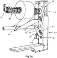
- FIG. 2a and 2 B show a roll holder of a label printer for a label roll 11 in two different views.
- the roll holder includes a frame, which is attached to a labeller, for example an F-Wrap labeller.
- the frame comprises a vertical support 21, which is continued by a holder 22 for a roller mount 80.
- the roller mount 80 is rotatably attached to the bracket 22 via ball bearings.
- the roll holder also includes a tensioning device 70 and a driver device 60.
- the roll holder includes a latching device 50 for latching the roll holder 80 in an axial position.
- the roll holder also includes a deflection roll 30, which is pivotably attached via a pivoting device 40 and defines the paper strip.
- the pivoting device 40 comprises a pivotable arm 41 which is pivotably mounted about a pivot point 42 .
- the deflection roller 30 is rotatably attached to the pivotable arm 41 .
- the pivotable arm 41 is pulled in a direction 48 by the spring force of a spring 46, in which the paper path defined by the deflection roller 30 between the label roll 11 and the print head becomes longer.
- a plunger 45 of a pneumatic cylinder 44 moves the pivotable arm 41 in an opposite direction 47, in which the paper path defined by the deflection roller 30 between the label roll 11 and the print head becomes shorter. This movement is limited by a stop 49 for the pivotable arm.
- a flexible steel band 62 is attached to the pivotable arm 41, in particular near the pivot point 42, which is guided over a brake disk.
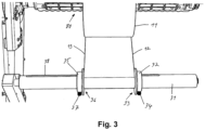
- the deflection roller 30 for the paper tape.
- the paper tape which is unwound from the label roll 11, wraps around a rotatable roller 31 of the deflection roller 30.
- the paper tape comprises a first side edge 12 and a second side edge 13 Leading paper path, the deflection roller 30 includes a paper guide device.
- a first guide element 32 which is movable in the axial direction and which can be fixed in an axial position on the rotatable roller 31 with a first fixation 34 .
- a second guide element 35 that can be moved in the axial direction is attached to the rotatable roller 31 and can be fixed in an axial position on the rotatable roller 31 with a second fixation 37 .
- the side edges 12, 13 of the paper strip slide along the inner sides 33, 36 of the respective guide element 32, 35.
- the guide elements 32, 35 are fixed in the axial direction in such a way that the distance between the inner sides 33, 36 of the guide elements 32, 35 corresponds to the width of the paper strip , possibly corresponds to the width of the paper tape including a small tolerance, the paper tape wraps tightly around the rotatable roller 31 due to the paper tension and is guided in a defined manner.
- the rotatable roller 31 further comprises markings 38 along its axial direction, which indicate positions for an arrangement of the guide elements on the deflection roller.
- the markings 38 are related to the position of the at least one print head and/or the paper width of the label roll. This means that the markings 38 show an operator at which position in the axial direction he must fix the guide elements 32, 35 for a specific paper roll 11 with a defined width and a predetermined pressure field.
- the locking device 50 consists of a movable retaining plate 51 which engages with one end 53 in a slot 54 in the roller holder 80, in particular in a slot 54 of a closing element 64 of the roller holder 80.
- the locking device 50 includes a locking guide 52 which is fixed to the bracket 22 of the vertical support 21 is connected.
- the holding plate 51 can be moved linearly in the locking guide 52 .
- the retaining plate 51 is by a pneumatic cylinder 55 in the Locking position moved in the direction of the roll holder. In 4 the view of the pneumatic cylinder 55 is obscured. If the pneumatic cylinder 55 is vented, the holding plate 51 is pulled by a spring 56 into a release position in which the end 53 of the holding plate 51 no longer engages in the slot 54 .
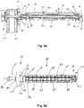
- Figures 5a and 5b show a roll holder for a label printer.
- the roll holder is shown in a sectional drawing.
- Figure 5b shows a plan view of the roll holder.
- the roll holder is rotatably fastened with its horizontal axis 81 via ball bearings 82 in a holder 22 .
- the bracket 22 continues a vertical support of the label printer in the vertical direction.
- the axis 81 is with reference to 7 described below.
- Fig. 12 shows the roll holder entraining device 60, which is referred to with reference to Figs Figures 6a and 6b is described below.
- Figures 5a and 5b also show the fixture 70 referred to in FIG 9a, 9b and 9c is described below.
- the roll holder includes a roll mount 80.
- the roll mount 80 consists of a base body 84 (see also Figures 8a and 8b ), which is linearly displaceable on the axis 81 via linear ball bearings 86, 87 with angular error compensation.
- the path of travel of the linear ball bearings 86, 87 on the axis 81 is not limited by stops on the axis 81, since this path of travel is limited by the driver device 60.
- the base body 84 of the roller mount 80 is designed as an elongate tube 89 which is placed on the axle 81 via the linear ball bearings 86, 87.
- the tube 89 On the outside of the tube 89 are three rails 88 which run in the axial direction and are open in the radial direction.
- the rails 88 there are clamping plates 83 that can be moved in the axial and in the radial direction, the clamping plates 83 having links 93 arranged at an angle, which can be moved via fixed pins 94 .
- the pins 94 are in bores 91 of the rails 88 held.
- the pins 94 thus form a fixed guide for the links 93 within the rails 88.
- Supporting elements 85 are arranged between the rails 88 on the outside of the base body 84 and are fastened in screw connections 92 of the base body 84 .
- the support elements 85 interrupted by the rails 88, bind a round contour of the roll mount 80.
- the rails 88 have a smaller radial extension than the support elements 85. The support elements 85 thus form a roll mount on which the roll core is placed.
- the diameter of the roll mount 80 formed by the support elements 85 is slightly smaller than the inside diameter of the roll core, so that the label roll 11 can be easily pushed onto the roll mount 80 .
- the clamping plates 83 protrude from the rails 88 and are radially displaceable.
- the radial displaceability of the clamping plates 83 extends from an area in which the outer sides of the clamping plates 83 do not protrude radially beyond the carrying elements 85 to an area in which the outer sides of the clamping plates 83 protrude radially beyond the carrying elements 85 . This makes it possible to clamp the roll core on the roll holder 80 by radially displacing the clamping plates 83 .
- the roll holder also includes a driver device 60, which transmits to the axis 81 a rotary movement of the roll holder 80, which takes place as a result of the paper strip of the label roll 11 being unwound.
- the driver device 60 comprises, as in Figure 6b shown a sleeve 62, in the inner region 69 of which the roller mount 80, in particular a closing element 64 ( Figure 6a ), which is connected to the base body 84 of the roller mount 80 is screwed with screws 65, is mounted axially movable.
- the closing element 64 includes a pin 63 which engages in an axial slot 66 of the sleeve 62 . An axial movement of the closing element 64 in the sleeve 62 is thus possible.
- the driver device 60 limits the path of travel of the roller mount 80 on the axis 81 of the roller holder in the axial direction.
- the sleeve 62 is attached to the axle 81 in a rotationally fixed manner.
- the non-rotatable connection is produced in particular via a bore 67 in a wall of the sleeve and an associated recess 68 in the bore 67 .
- the sleeve 62 is fitted with the bore 67 in a receiving area 67' on the axle 81, the axle comprising a nose 68' which engages in the recess 68 and forms the non-rotatable connection.
- the sleeve 62 includes bores 61 ′ in a side wall, via which the sleeve is connected to a brake disk 61 .
- the brake disc 61 is braked via a flexible steel band 62 when the pivotable arm 41 of the pivot device 40 is moved by the spring force of the spring 46 in a direction in which the paper path is lengthened.
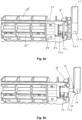
- Figure 8b shows bores 90, which are present in the axial direction in the base body 84, in which a cylinder 73 of the clamping device 70 is fastened with screws. Equally are on the other, in Figure 8b There are holes on the rear and therefore not visible side of the base body, in which the closing element 64 is screwed to the base body with screws.
- the clamping device 70 is in the 9a, 9b , and 9c shown. Basically, the clamping device 70 has the function of axially displacing the clamping plates 83 relative to the base body 84 in the slots 88 of the base body 84 .
- the radial position of the clamping plates 83 with respect to the center depends on the links 93 in the clamping plates 83 and through the pins 94, which are firmly connected to the base body 84 of the base body 84 from the axial position of the clamping plates 83 in the slots 88 of the base body 84.
- two adjustment mechanisms are implemented via the clamping device 70 in order to adapt the radial position of the clamping plates 83 in the base body 84, both mechanisms being implemented with the cooperation of an adjustment element 72.
- the first mechanism changes the position of the clamping plates by turning the adjustment element 72 and serves to establish a basic setting.
- the second mechanism is effected by transferring an operating lever 71 from a working position in which the operating lever is oriented perpendicularly to the axis 81 to an installation position in which the operating lever is oriented parallel to the axis 81 .
- this mechanism is used to tighten the label roll by moving the operating lever 71 from the installation position to the working position, i.e. to move the clamping plates 83 radially outwards with this transfer of the operating lever 71 .
- the adjusting element 72 is in particular made in one piece and consists of a rotary element 72a, a holder 72b for the operating lever 71, a driver disk 72c and a sleeve 72d.
- the sleeve 72d forms the main body of the adjustment element 72 and is open on one side.
- the drive disk 72c is mounted on the sleeve 72d and the rotary element 72a is mounted on the axial end of the sleeve 72d opposite the opening. In the axial direction between driver disk 72c and rotary element 72a there is a defined distance, in which the clamping plates 83 engage with a coupling device 94 .
- the coupling device 94 is designed as a hook that can be inserted from the outside into engages in the gap between drive plate 72c and rotary element 72a, the hook being formed by a metal sheet that has the width of the gap between drive plate 72c and rotary element 72a.
- the sheet metal is touched on one side by the drive plate 72c and on the other side by the rotating element 72a. If the adjustment element 72 is displaced in the axial direction, the clamping plates 83 are also displaced in the axial direction via the coupling device 94 . Since driver disk 72c and rotary element 72a are concentric in the area in which they touch coupling device 94, this effect is present regardless of the rotary position in which adjustment element 72 is located.
- the adjusting element 72 is mounted with the sleeve 72d on a cylinder 73, the cylinder forming a sliding surface for the sleeve 72d.
- the cylinder 73 is firmly connected to the base body 84 .
- a screw 77 is screwed into an internal thread of the cylinder 73 .
- the operating lever 71 is tiltably attached to the screw head 74 . Turning the screw 77 changes the distance between the cylinder 73 and the operating lever 71.
- the operating lever 71 is placed in the holder 72b of the adjusting element 72 in such a way that it can be tilted, but is connected in a rotationally fixed manner in the direction of rotation of the screw 77 .
- Rotating the rotary member 72a consequently rotates the operating lever 71 about the axial direction of the screw 77 and screws the screw 77 in or out of the cylinder 73.
- the distance between the operating lever 71 and the cylinder 73 is reduced or increased.
- rotating the rotary element 72a changes the distance between the base body 84 and the area between the driver disk 72c and the rotary element 72a, and the clamping plates 83 thus move in the slots 88 of the base body in the axial direction.
- This causes a change in the radial position of the clamping plates 83 via the link 93.
- the adjusting element 72 the diameter of a cylinder, the is spanned by the outer edges of the clamping plates 83 can be changed.
- the operating lever 71 has an eccentric 75 at its end at which it is tiltably connected to the screw head 74 of the screw 77.
- a washer 76 rests on the screw 77 on the eccentric. This in turn rests against the setting element 72 . If the operating lever 71 is moved from the installation position (not shown in the drawings, in extension of the axis 81) to the working position ( Figures 9a and 9b ) is tilted from the horizontal position to the vertical position by turning the screw head 74, the eccentric 75 shifts the washer 76 on the screw 77 in the direction of the cylinder 73.
- the setting element 72 is moved in the direction of the base body 84 .
- the clamping plates 83 are pushed radially outwards.
- DSP digital signal processor
- ASIC application specific integrated circuit
- FPGA field programmable gate array
- ROM read only memory
- RAM random access memory
Landscapes
- Unwinding Webs (AREA)
- Handling Of Continuous Sheets Of Paper (AREA)
Abstract
Description
- Die vorliegende Erfindung betrifft einen Rollenhalter für eine Etikettenrolle und einen Etikettendrucker, insbesondere einen Etikettendrucker mit einem Rollenhalter für eine Etikettenrolle.
- Etikettendrucker, insbesondere Etikettendrucker zum Auszeichnen von Packungen für Lebensmittel, umfassen einen drehbaren Rollenhalter, der zum Tragen einer Etikettenrolle aus einem aufgewickelten Papierband vorgesehen ist. Beim Druck wird das Papierband abgerollt und entlang eines Papierpfades zu einem Druckkopf befördert. Der Rollenhalter umfasst zum Beispiel einen Anschlag in axialer Richtung, an dem die Etikettenrolle, insbesondere der Kern der Etikettenrolle, beim Aufbringen auf den Rollenhalter angeschlagen wird, so dass sich die Etikettenrolle entlang der axialen Richtung des Rollenhalters in einer definierten Position befindet. Sind die einzelnen Papierlagen der Etikettenrolle exakt übereinander auf der Etikettenrolle aufgerollt, so befinden sich beim Abrollen des Papierbandes dessen Ränder immer in einer vorgesehenen axialen Position. Das unter Spannung stehende Papierband wird deshalb entlang des Papierpfades nicht verdreht.
- Die meisten der bekannten Etikettenrollen sind so aufgerollt, dass die Ränder der einzelnen Papierlagen der Etikettenrolle sich exakt übereinander befinden. Die Seiten der Etikettenrolle fluchten entlang ihres Durchmessers.
- Im Lebensmittelbereich kommen jedoch immer mehr sogenannte F-Wrap oder C-Wrap Verpackungen zum Einsatz. Diese Verpackungen werden mit einem Etikett ausgezeichnet, das sich nicht nur auf einer Seite der Verpackung befindet, sondern die Verpackung komplett umläuft (F-Wrap) oder auf drei Seiten der Verpackung angebracht ist (C-Wrap). Diesen Verpackungen ist gemein, dass das aufzubringende Etikett eine längliche Form hat, das heißt, die Ausdehnung des Etiketts in einer Richtung ist wesentlich größer, zum Beispiel vier bis acht Mal so groß, als die Ausdehnung des Etiketts in der dazu senkrecht stehenden Richtung. Wenn die Rollenbreite einer Etikettenrolle mit F-Wrap oder C-Wrap Etiketten der Länge des Etiketts entspricht, können bei gleichem Rollendurchmesser wesentlich mehr Etiketten aufgewickelt werden, als wenn die Rollenbreite der kurzen Seite des Etiketts entspricht. Eine derartige Etikettenrolle umfasst eine Rollenbreite zum Beispiel zwischen 30 cm und 50 cm. Etikettenrollen, insbesondere Linerless-Etikettenrollen ohne Trägerband, dieser Breite können aus produktionstechnischen Gründen oft nicht so aufgerollt werden, dass die Ränder der einzelnen Papierlagen des Papierbandes eine Flucht bilden. Vielmehr weisen diese Etikettenrollen an ihren Seiten oft einen S-förmigen Verlauf auf, was dazu führt, dass bei einer axialen Ausrichtung des Rollenkerns auf dem Rollenhalter nicht automatisch eine axiale Ausrichtung der Seitenränder des Papierbandes über die gesamte Papierlänge erreicht werden kann. Vielmehr bewegen sich bei einem in axialer Richtung feststehenden Rollenkern während des Abrollvorgangs des Papierbandes dessen Seitenränder in axialer Richtung hin und her. Diese axiale Bewegung des Papierbandes führt bei einem definierten Papierpfad zu einem Verdrehen des Papierbandes entlang des Papierpfades und im schlimmsten Fall zu Fehlfunktionen des Etikettendruckers.
- Aus dem Stand der Technik ist eine Vorrichtung bekannt, bei der ein Papiersensor einen Rand des abgerollten Teils des Papierbandes detektiert und aufgrund der aktuellen Position des Randes des Papierbandes beziehungsweise der Richtung, in der sich der Rand des Papierbandes gerade bewegt, mit Hilfe eines Motors die axiale Position des Rollenhalters und somit die axiale Position des Rollenkerns so steuert, dass die axiale Verschiebung des Papierbandes auf der Etikettenrolle ausgeglichen wird. Das Papierband wird sicher durch den Papierpfad geleitet und es findet kein Verdrehen des Papiers statt. Eine derartige Rollenhalterung ist jedoch aufwändig und teuer.
- Aufgabe der Erfindung ist es, eine kostengünstigere und weniger wartungsanfällige Lösung zu finden.
- Diese Aufgabe wird durch einen Rollenhalter nach Anspruch 1 und einen Etikettendrucker nach Anspruch 14 gelöst.
- Erfindungsgemäß wird ein Rollenhalter für eine Etikettenrolle vorgeschlagen. Bei der Etikettenrolle handelt es sich insbesondere um eine Linerless-Etikettenrolle, das heißt um eine Etikettenrolle ohne Trägerband. Die Etikettenrolle ist insbesondere quer aufgerollt. Darunter versteht der Fachmann, dass es sich um ein Papierband aus mehreren nebeneinander angebrachten Etiketten, ein sogenanntes Endlosband, handelt, wobei die Etiketten mit der langen Seite in Abrollrichtung der Etikettenrolle nebeneinander liegen, so dass die kurze Seite jedes Etiketts der Längsrichtung des Papierbandes entspricht. Das Papierband ist dazu vorgesehen, dass einzelne Etiketten von dem Papierband mit einer Schneideinheit abgetrennt werden, ggf. vor oder nach dem Abtrennen durch einen Etikettendrucker bedruckt werden und dann durch eine entsprechende Vorrichtung auf einer Verpackung insbesondere als F-Wrap oder als C-Wrap Etikett appliziert werden. In einer Ausführungsform liegt die Breite der Etikettenrolle und somit die lange Seite eines Etiketts zwischen 150°mm und 500°mm. In einer Ausführungsform ist die kurze Seite des Etiketts zwischen 50°mm und 150°mm lang. In einer Ausführungsform ist das Papierband, das auf der Etikettenrolle aufgewickelt ist, mehrere hundert Meter lang.
- Der Rollenhaller umfasst eine horizontal angeordnete Achse, die an mindestens einer Seite von einem Gestell gehalten ist. In einer Ausführungsform wird die horizontal angeordnete Achse an einer Seite von einem Gestell gehalten, während die andere Seite der Achse freischwebend und somit nicht abgestützt ist.
- Der Rollenhalter umfasst des Weiteren eine drehbare Rollenaufnahme, die parallel zur Achse ausgerichtet ist und auf der Achse aufgebracht ist. Die Rollenaufnahme ist mit mindestens einem Linearlager auf der Achse aufgebracht und über das mindestens eine Linearlager auf der Achse linear verschiebbar. In einer Ausführungsform sind zwei Linearlager vorhanden, die eine Verschiebbarkeit der Rollenaufnahme auf der Achse ermöglichen, wobei die beiden Linearlager insbesondere an den axialen Endbereichen der Rollenaufnahme angebracht sind.
- Der Fachmann versteht unter einem Linearlager in diesem Zusammenhang ein Lager, dass es ermöglicht, die Rollenaufnahme auf der Achse entlang beider axialen Richtungen, das heißt auf der Achse vor und zurück zu verschieben. Der Begriff Linearlager umfasst keine Aussage darüber, ob das Lager eine Drehung der Rollenaufnahme auf der Achse zulässt oder blockiert.
- Das hat den Vorteil, dass eine Etikettenrolle, die an einer definierten Position auf der Rollenaufnahme gehalten wird, mit Bezug zur Achse linear verschiebbar ist. Bei einer Etikettenrolle, deren Papierlagen im Bezug zum Rollenkern einen S-förmigen Verlauf aufweisen und somit die einzelnen Papierlagen im Bezug zum Rollenkern eine axiale Verschiebung aufweisen, kann diese Verschiebung durch eine entgegengesetzte Verschiebung der Rollenaufnahme ausgeglichen werden, so dass ein Verdrehen des Papierbandes im Papierpfad verhindert wird. Dies ist insbesondere bei breiten Etikettenrollen von Vorteil. Da das Papierband im Papierpfad unter Spannung steht und das Linearlager in axialer Richtung eine leichtgängige Verschiebung zwischen Achse und Rollenhalter ermöglicht, richtet sich der Rollenhalter durch die Papierspannung auf die entsprechende axiale Position der Papierbahn aus, falls die Papierränder im Papierpfad an einer definierten Position geführt oder gehalten werden. Ein Sensor zum Detektieren der aktuellen Papierposition entlang der axialen Richtung und eine Steuereinheit mit motorischer Stelleinheit zum axialen Bewegen des Rollenhalters kann entfallen.
- In einer Ausführungsform ist das Linearlager ein Gleitlager.
- In einer Ausführungsform ist das Linearlager ein Linearkugellager, insbesondere ein Linearkugellager mit Winkelfehlerausgleich. Ein Linearkugellager erlaubt eine Linearverschiebung des Rollenhalters auf der Achse mit geringem Reibungswiderstand. Dies ist vorteilhaft, da die lineare Verschiebung des Rollenhalters auf der Achse des Rollenhalters durch die Papierspannung des Papierbandes im Papierpfad erfolgt. Eine leichtgängige lineare Verschiebung des Rollenhalters unterstützt die Funktion des Mechanismus. Ein Linearkugellager mit Winkelfehlerausgleich ist notwendig, wenn die Achse sich aufgrund des Gewichts der Etikettenrolle geringfügig verbiegt. Da das Gewicht der Etikettenrollen mehrere 10 kg, insbesondere über 25 kg beträgt, kommt es insbesondere bei einer Achse, die an einem Ende freischwebend ist, immer zur leichten Verbiegung, die durch ein Linearlager mit Winkelfehlerausgleich ausgeglichen wird. Das Linearlager mit Winkelfehlerausgleich gleicht neben der Biegung der Achse auch Fluchtungsfehler der Gehäusebohrungen bzw. der Halterung der Achse im Gehäuse aus.
- In einer Ausführungsform ist die Achse drehfest mit dem Gestell verbunden. Die Rollenaufnahme ist drehbar auf der Achse aufgebracht. Insbesondere ist das mindestens eine Linearlager ein Linearkugellager, welches sowohl eine axiale Bewegung als auch eine Rotationsbewegung der Rollenaufnahme auf der Achse ermöglicht. Die axiale Bewegbarkeit der Rollenaufnahme auf der Achse durch das Linearkugellager gleicht den Versatz der einzelnen Papierlagen quer zur Abrollrichtung auf der Etikettenrolle aus. Das Linearkugellager ermöglicht auch eine Rotationsbewegung der Rollenaufnahme auf der Achse zum Abrollen des Papierbandes von der Etikettenrolle.
- In einer Ausführungsform ist die Achse drehbar vom Gestell gehalten. Die Rollenaufnahme ist drehfest und linear bewegbar mit der Achse verbunden. In einer Ausführungsform ist die Rollenaufnahme über einen Mitnehmer drehfest mit der Achse verbunden und der Mitnehmer überträgt eine Rotation der Rollenaufnahme auf die Achse. In einer Ausführungsform ist in der Ausführungsform mit Mitnehmer das Linearlager ein Linearkugellager. Der Mitnehmer verhindert die Rotationsbewegung der Rollenaufnahme auf der Achse, allerdings würde diese Rotationsbewegung durch das Linearkugellager grundsätzlich ermöglicht werden. Das Linearkugellager, insbesondere ein Linearkugellager mit Winkelfehlerausgleich hat jedoch den Vorteil, dass Toleranzen ausgeglichen werden. So ist die Nutzung eines Linearkugellagers auch in dieser Ausführungsform vorteilhaft.
- In einer Ausführungsform besteht der Mitnehmer aus einer Hülse mit einem Schlitz in axialer Richtung. Die Hülse ist drehfest mit der Achse verbunden. Darunter ist auch zu verstehen, dass die Hülse und die Achse nicht direkt miteinander verbunden sind, sondern über ein Zwischenelement. Der technische Effekt besteht darin, dass eine Rotationsbewegung, die an der Hülse verursacht wird, auch eine Rotationsbewegung der Achse verursacht. Ein mit der Rollenaufnahme verbundener Stift greift in den Schlitz des Mitnehmers ein. Das hat den Vorteil, dass eine Rotationsbewegung der Rollenaufnahme mit Hilfe des Stiftes auf die Hülse übertragen wird. Durch die drehfeste Verbindung von Hülse und Achse wird die Rotationsbewegung auf die Achse übertragen. Wird die Etikettenrolle, die sich auf der Rollenaufnahme befindet, abgerollt, indem an dem Papierband eine Kraft in Richtung des Papierpfades ausgeübt wird, so entsteht in der Rollenaufnahme eine Rotationsbewegung, die zu einer Rotationsbewegung der Achse führt. Gleichzeitig ist durch die Ausgestaltung der Hülse mit einem Schlitz in axialer Richtung und der drehfesten Verbindung zwischen Rollenaufnahme und Hülse, durch den Stift, der in den Schlitz eingreift, ein Mitnehmer geschaffen, der in Richtung des Schlitzes, das heißt in axialer Richtung, verschiebbar ist. Das ermöglicht eine Verschiebung der Rollenaufnahme auf der Achse in axialer Richtung und die gleichzeitige drehfeste Verbindung zwischen Rollenaufnahme und Achse.
- In einer Ausführungsform ist die Hülse des Mitnehmers oder die Achse drehfest mit einer Bremsscheibe verbunden. Die Bremsscheibe ist durch ein Band mit einer sich im Papierpfad befindlichen Umlenkrolle verbunden. In einer Ausführungsform ist das Band um die Bremsscheibe herumgeführt, so dass sich Bremsscheibe in einer durch das Band gebildeten Schlinge dreht. Wird das Band angespannt, indem an dem Ende des Bandes in eine Richtung weg von der Bremsscheibe gezogen wird, so übt es eine Reibungskraft auf die Bremsscheibe aus und bremst die Bremsschiebe ab. In einer Ausführungsform ist ein Ende des Bandes in einer festen Position fixiert. Das andere Ende des Bandes ist an einem beweglichen Halter für eine Umlenkrolle des Papierpfades fixiert. Lässt die Spannung des Papierbandes im Papierpfad nach, so bewegt sich der Halter und bewegt das Ende des Bandes und es wirkt so eine Bremskraft auf die Bremsscheibe. In einer Ausführungsform ist das Band aus dehnbarem Material gebildet. In einer Ausführungsform ist das Band aus einem biegeflexiblen, aber nicht dehnbaren Material gebildet, insbesondere aus einem Blech, insbesondere einem Stahlblech, insbesondere einem Stahlblech mit der Dicke zwischen 0,15°mm und 0,45°mm, insbesondere 0,3°mm gebildet.
- In einer Ausführungsform besteht der Rollenhalter aus einem Grundkörper, insbesondere aus einem rohrförmigen Grundkörper. An dem Grundkörper ist mindestens eine Schiene, insbesondere drei Schienen angebracht, die in radialer Richtung offen sind. Der Grundkörper ist über das mindestens eine Linearlager linear bewegbar auf der Achse aufgebracht. Die mindestens eine Schiene führt ein zumindest radial bewegbares Spannelement, insbesondere ein Spannblech. In einer Ausführungsform ist in jeder Schiene ein Spannblech radial und axial bewegbar geführt.
- In einer Ausführungsform weist der Rollenhalter an seinem axialen Ende einen Bedienhebel auf. Der Bedienhebel ist über einen Exzenter von einer Arbeitsposition in eine Installationsposition überführbar. Im Sinne dieser Offenbarung ist unter einem Exzenter ein Element zu verstehen, das um einen Drehpunkt herum drehbar ist, bei dem die Distanz zwischen dem Drehpunkt und einem Rand des Elements gemessen in der horizontalen Ebene sich verändert, wenn das Element gedreht wird.
- In einer Ausführungsform steht der Bedienhebel in der Installationsposition in Verlängerung zur Achse des Rollenhalters vom Rollenhalter ab, das heißt, der Bedienhebel ist seiner Längsrichtung nach in der axialen Richtung der Achse ausgerichtet. Das mindestens eine Spannblech wird durch Bewegen des Bedienhebels von der Installationsposition in die Arbeitsposition über den Exzenter in radialer Richtung verstellt.
- In einer Ausführungsform umfasst das mindestens eine Spannblech eine Kulisse, die an einem Stift in der mindestens einen Schiene des Grundkörpers läuft. Die Kulisse ist derart angeordnet, dass eine Bewegung des Spannblechs in eine axiale Richtung des Grundkörpers zu einer radialen Verschiebung des Spannblechs nach außen führt und eine Bewegung des Spannblechs in die andere axiale Richtung des Grundkörpers zu einer radialen Verschiebung des Spannblechs nach innen führt. In einer Ausführungsform wirken Exzenter und Spannblech derart zusammen, dass eine Bewegung des Bedienhebels von der Installationsposition in die Arbeitsposition zu einer Verschiebung des Spannblechs in axialer Richtung führt, durch die das Spannblech durch die Kulisse in radialer Richtung nach außen geführt wird. Der Exzenter und das Spannblech wirken derart zusammen, dass eine Bewegung des Bedienhebels von einer Arbeitsposition in eine Installationsposition zu einer Verschiebung des Spannblechs in axialer Richtung führt, durch die das Spannblech durch die Kulisse in radialer Richtung nach innen geführt wird.
- In einer Ausführungsform ist ein Einstellelement mit dem Bedienhebel gekoppelt. Ein Drehen des Bedienhebels entlang oder gegen die Rotationsrichtung des Grundkörpers bewirkt ein Bewegen des mindestens einen Spannblechs in axialer Richtung des Grundkörpers. In einer Ausführungsform ist das Einstellelement formschlüssig in Rotationsrichtung des Grundkörpers mit dem Bedienhebel verbunden, so dass ein Drehen des Bedienhebels ein Drehen des Einstellelements bewirkt. Durch Drehung des Einstellelements wird der Abstand zwischen Grundkörper und Einstellelement verändert. Das Einstellelement umfasst des Weiteren einen Mitnehmer für das mindestens eine Spannblech, mit dem das Spannblech in axialer Richtung mit dem Einstellelement verschoben wird.
- In einer Ausführungsform umfasst der Rollenhalter, insbesondere der Grundkörper, eine Rastvorrichtung zum Verrasten der Rollenaufnahme in einer Mittelposition entlang eines Verschiebeweges der Rollenaufnahme auf der Achse. Dabei ist Mittelposition nicht so auszulegen, dass die Rollenaufnahme von der Mittelposition weg einen exakt gleichen Verfahrweg in beide axialen Richtungen aufweisen muss. Vielmehr ist Mittelposition so zu verstehen, dass die Verrastung im Wesentlichen mittig des Verfahrwegs stattfindet, so dass die Bewegung in beide axialen Richtungen nach aufheben der Verrastung möglich ist. Durch die Verrastung wird die Rollenaufnahme nicht in einer axialen Endposition verrastet.
- Erfindungsgemäß wird ein Etikettendrucker zum Bedrucken eines auf einer Etikettenrolle aufgewickelten Papierbandes vorgeschlagen. Der Etikettendrucker umfasst einen Rollenhalter für die Etikettenrolle und mindestens einen Druckkopf zum Bedrucken des Papierbandes. Der Etikettendrucker weist einen Papierpfad auf, der entlang der Bewegungsrichtung des Papierbandes von dem Rollenhalter zum Druckkopf verläuft. In einer Ausführungsform wird das Papierband zwischen Rollenhalter und Druckkopf durch ein Schneidgerät in einzelne Etiketten vereinzelt. Auch in diesem Fall ist der Papierpfad als die Bewegungsrichtung vom Rollenhalter zum Druckkopf zu verstehen. Der Etikettendrucker umfasst entlang des Papierpfads eine Umlenkrolle, entlang derer das Papierband geführt ist. Die Umlenkrolle hat den Effekt, dass der Papierpfad an der Umlenkrolle seine Richtung ändert und die Umlenkrolle das Papierband entsprechend führt. Der Etikettendrucker umfasst einen Rollenhalter in einer der vorab beschriebenen Ausführungsformen.
- In einer Ausführungsform umfasst die Umlenkrolle eine Papierführungsvorrichtung. Die Papierführungsvorrichtung umfasst auf jeder Seite des Papierbandes ein Führungselement, wobei die Führungselemente in axialer Richtung der Umlenkrolle verstellbar und feststellbar sind. In einer Ausführungsform sind die Führungselemente motorisch verstellbar. In einer Ausführungsform sind die Führungselemente händisch verstellbar. In einer Ausführungsform sind die Führungselemente miteinander gekoppelt, so dass das Verstellen eines Führungselements in einer Richtung zum Verstellen des anderen Führungselements in entgegengesetzter Richtung führt. Die Führungselemente bilden eine Führung für die Ränder des Papierbandes. Da das Papierband an der Umlenkrolle unter Spannung steht, wird über die Führungselemente die axiale Position des Papierbandes an der Umlenkrolle definiert. Die axiale Position des Rollenhalters läuft dieser Position entsprechend nach, so dass das Papierband nicht verdreht zwischen Papierrolle und Umlenkrolle geführt wird, unabhängig davon, ob die oberste Papierlage einen Versatz zum Rollenkern hat.
- In einer Ausführungsform umfasst die Umlenkrolle entlang ihrer axialen Richtung Markierungen, die Positionen für eine Anordnung der Führungselemente an der Umlenkrolle anzeigen. Die Markierungen stehen im Zusammenhang mit der Position des mindestens einen Druckkopfes und/oder der Papierbreite der Etikettenrolle. Das hat den Vorteil, dass die Markierungen dem Bediener die Positionen der Führungselemente anzeigen, auf die die Führungselemente bei einer gewissen Papierbreite eingestellt werden müssen, um das Papierband an der richtigen Position dem Druckkopf für einen Druck in einem vorgesehenen Feld zuzuführen.
- In einer Ausführungsform umfasst der Etikettendrucker eine Steuerungsvorrichtung, die eine Eingabevorrichtung umfasst.
- Die Steuerungsvorrichtung empfängt von der Eingabevorrichtung mindestens eine Papierbreite einer Etikettenrolle. Die Steuerungsvorrichtung umfasst einen Prozessor, der aus der empfangenen Papierbreite axiale Positionen der Führungselemente auf der Umlenkrolle bestimmt. In einer Ausführungsform werden die axialen Positionen der Führungselemente auf der Umlenkrolle auf einer Anzeigeeinheit angezeigt. In einer Ausführungsform steuert der Prozessor eine Verstelleinheit an, die die Führungselemente motorisch an die bestimmten axialen Positionen auf der Umlenkrolle bewegt.
- In einer Ausführungsform wird die Umlenkrolle von einem schwenkbaren Arm gehalten. Durch Schwenken des Arms wird die Position der Umlenkrolle und somit der Papierpfad verändert. Der Arm ist durch eine Feder vorgespannt und die Feder zieht den Arm in eine Richtung, in der die Strecke entlang des Papierpfades zwischen Rollenhalter und Druckkopf länger wird. Die Spannung des Papierbandes zieht den Arm in eine Richtung, in der die Strecke entlang des Papierpfades zwischen Rollenhalter und Druckkopf kürzer wird. Die Spannung des Papierbandes bzw. durch Anspannen des Papierbandes wird der Arm entgegen der Federkraft gezogen. Das hat den Effekt, dass beim Transport des Papierbandes zum Beispiel durch eine Transportwalze, das Papier angespannt wird und die Umlenkrolle in eine Richtung zieht, in der der Papierpfad kürzer wird. Dies ermöglicht eine schnelle, ruckartige Beschleunigung des Papierbandes. Die Federkraft zieht den Arm in die entgegengesetzte Richtung. Insbesondere wenn das Papierband nicht transportiert wird, überwiegt die Federkraft die Spannung des Papierbandes und der Arm wird in eine Richtung gezogen, in der der Papierpfad länger wird.
- Erklärend wird hier angemerkt, dass der Ausdruck "Strecke von der Umlenkrolle zum Druckkopf" zur Veranschaulichung dient. Aufgrund des über die Druckzeit abnehmenden Papierrollendurchmessers und der Tatsache, dass immer die oberste Papierlage einer Papierrolle abgewickelt wird, verändert sich die exakte Papierführung je nach Durchmesser der Papierrolle. Der Fachmann im Bereich Etikettendrucker ist jedoch mit der Auslegung des Ausdrucks Papierpfad wohl vertraut. In einer Ausführungsform definiert die Umlenkrolle einen Umlenkpunkt für das Papierband im Papierpfad. Das Papierband läuft mit seiner flachen Seite über die Umlenkrolle. In einer Ausführungsform läuft das Papierband mit seiner nicht-klebenden Seite über die Umlenkrolle. In einer Ausführungsform läuft das Papierband mit seiner klebenden Seite über die Umlenkrolle, wobei die Umlenkrolle mit einer Ani-Haftbeschichtung versehen ist. Die klebende Seite des Papierbandes umfasst in einer Ausführungsform mehrere Längsstreifen aus Klebematerial, wobei die Längsstreifen im Vergleich zur Breite des Papierbandes schmal ausgebildet sind. In einer Ausführungsform sind die Längsstreifen aus Klebematerial an den Stellen, an denen das Papierband zum Abtrennen einzelner Etiketten vorgesehen ist, unterbrochen.
- In einer Ausführungsform umfasst der Etikettendrucker einen Aktuator, insbesondere einen Pneumatikzylinder. Der Aktuator bewegt den Arm entgegen der Federkraft in eine Installationsposition. In der Installationsposition ist die Strecke entlang des Papierpfads zwischen Rollenhalter und Druckkopf kurz. Das heißt, der Aktuator drückt den Arm entgegen der Federkraft, die, wie oben beschrieben, das Papierband spannt. Mit anderen Worten drückt der Aktuator den Arm in eine Position, in der das Papierband, falls ein Papierband im Papierpfad eingelegt ist, entspannt ist. Der Aktuator wird durch die Steuerungsvorrichtung des Etikettendruckers ausgelöst. In einer Ausführungsform löst die Steuerungsvorrichtung des Etikettendruckers den Aktuator dann aus, wenn ein Sensor das Öffnen der Abdeckhaube des Etikettendruckers detektiert oder die Steuerungsvorrichtung von der Eingabevorrichtung ein Signal empfängt, dass die Etikettenrolle gewechselt werden soll. Das hat den Effekt, dass der Aktuator den Arm und die Umlenkrolle in eine Position bewegt, in der nach Aufbringen einer neuen Etikettenrolle auf dem Rollenhalter das Papierband in den Papierpfad vom Rollenhalter zum Druckkopf eingelegt werden kann. Insbesondere wird beim Bewegen des Aktuators durch einen weiteren Aktuator ein Abstand zwischen einer Druckwalze und dem Druckkopf oder einer Transportwalze und einem Gegenhalter zur Transportwalze hergestellt, so dass das Ende des Papierbandes in den Abstand eingeführt werden kann. Wird folgend Transportwalze und Gegenalter oder Druckwalze und Druckkopf und der Arm wieder in die ursprüngliche Position verbracht, so ist der Etikettendrucker wieder betriebsbereit.
- In einer Ausführungsform ist das Band, welches mit der Bremsscheibe verbunden ist, mit einem Ende an dem schwenkbaren Arm befestigt. Das Band läuft zumindest über einen Teil des Umfangs der Bremsscheibe. In einer Ausführungsform läuft das Band in einer Schlinge oder in einem Teil einer Schlinge um die Bremsscheibe. Das Band wird um die Bremsscheibe gespannt, wenn der schwenkbare Arm sich mit der Federkraft bewegt und das Band wird um die Bremsscheibe entspannt, wenn der schwenkbare Arm sich entgegen der Federkraft bewegt. Das hat den Effekt, dass die Bremsscheibe und somit der Rollenhalter mit der Etikettenrolle abgebremst werden, wenn der Papierpfad länger wird, das heißt, wenn mehr Papier von der Rolle abgewickelt wird als mit dem Druckkopf verarbeitet wird. Somit wird ein Nachlaufen der Papierrolle beim Stoppen des Transportes des Papierbandes verhindert.
- In einer Ausführungsform umfasst der Rollenhalter, insbesondere der Grundkörper oder insbesondere ein Abschlusselement am Grundkörper, eine Rastvorrichtung zum Verrasten der Rollenaufnahme in einer Mittelposition entlang eines Verschiebeweges der Rollenaufnahme auf der Achse. Die lineare Verschiebbarkeit des Rollenhalters auf der Achse wird durch die Rastvorrichtung verhindert. Das ist vorteilhaft für den Wechsel der Papierrolle, da der Bediener nicht darauf achten muss, dass er beim Aufschieben der Papierrolle die Rollenaufnahme nicht in die Endposition des axialen Verschiebeweges bewegt und somit eine Verschiebbarkeit der Etikettenrolle nur in einer axialen Richtung gegeben wäre.
- Wenn der Rollenhalter mit der Rastvorrichtung insbesondere in der Mitte des axialen Verschiebeweges verrastet wird und in dieser axialen Position beim Aufbringen der Papierrolle bleibt, so kann sich der Rollenhalter im Druckbetrieb nach dem Lösen der Rastvorrichtung in beide axialen Richtungen bewegen. In einer Ausführungsform wird die Rastvorrichtung ausgelöst, wenn der Sensor für die Abdeckhaube ein das Öffnen der Abdeckhaube detektiert. In einer Ausführungsform ist die Rastvorrichtung mit dem Aktuator, insbesondere dem Pneumatikzylinder des Arms gekoppelt. In einer Ausführungsform besteht die Rastvorrichtung aus einem beweglichen Halteblech, das in einen Schlitz in den Rollenhalter eingreift.
- Einige Ausführungsformen der Erfindung sind in den Zeichnungen beispielhaft gezeigt und nachfolgend beschrieben. Es zeigen, jeweils in schematischer Darstellung:
- Fig. 1
- eine Schnittzeichnung einer Etikettenrolle,
- Fig. 2a
- einen Rollenhalter für einen Etikettendrucker in einer ersten Ansicht,
- Fig. 2b
- einen Rollenhalter für einen Etikettendrucker in einer zweiten Ansicht,
- Fig. 3
- eine Umlenkrolle,
- Fig. 4
- eine Rastvorrichtung für einen Rollenhalter,
- Fig. 5a
- eine Schnittzeichnung von einen Rollenhalter,
- Fig. 5b
- einen Rollenhalter,
- Fig. 6a
- einen Mitnehmer eines Rollenhalters,
- Fig. 6b
- eine Hülse für den Mitnehmer eines Rollenhalters,
- Fig. 7
- eine Achse eines Rollenhalters,
- Fig. 8a
- eine Rollenaufnahme eines Rollenhalters in einer ersten Ansicht,
- Fig. 8b
- eine Rollenaufnahme eines Rollenhalters in einer zweiten Ansicht,
- Fig. 9a
- eine Spannvorrichtung eines Rollenhalters in einer ersten Ansicht,
- Fig. 9b
- eine Spannvorrichtung eines Rollenhalters in einer zweiten Ansicht, und
- Fig. 9c
- Spannbleche und ein Einstellelement der Spannvorrichtung.
-
Fig. 1 zeigt eine Schnittzeichnung durch eine Etikettenrolle 11. Die Zeichnung dient zur Illustration des Effekts, dass die einzelnen Papierlagen 14a, 14b, 14c an den Rändern nicht plan in der vertikalen zueinander aufgerollt sind. Dieser Effekt ist besonders ausgeprägt, wenn es sich um quer auf gewickelte und damit sehr breite Etikettenrollen 11, wie sie zum Beispiel für eine F-Wrap Etikettierung benutzt werden, handelt. Eine solche Etikettenrolle 11 ist zum Beispiel bis 50 cm breit. Die Etikettenrolle 11 ist um einen Rollenkern 13 aufgewickelt. Der Mittelpunkt des Rollenkerns 13 definiert die Achse 12 der Etikettenrolle 13, um die das Endlosband der Etikettenrolle 11 abgewickelt wird. Die einzelnen Papierlagen 14a, 14b, 14c des Endlosbandes sind fortlaufend auf der Etikettenrolle 11 aufgewickelt. Durch den Produktionsprozess entsteht eine horizontale Verschiebung der einzelnen Papierlagen 14a, 14b, 14c, sodass am linken und rechten vertikalen Rand der Etikettenrolle 11 Ausbuchtungen 16 und Einbuchten 15 entstehen. Das heißt, die einzelnen Papierlagen 14a, 14b, 14c können horizontal zueinander verschoben sein. Da immer die oberste Papierlage abgewickelt wird, entsteht beim Abwickeln des Papierbandes von der Etikettenrolle 11 eine vertikale Verschiebung des Papierbandes. -
Fig. 2a und2b zeigen einen Rollenhalter eines Etikettendruckers für eine Etikettenrolle 11 in zwei verschiedenen Ansichten. Der Rollenhalter umfasst ein Gestell, welches an einem Etikettierer, zum Beispiel einem F-Wrap Etikettierer angebracht ist. Das Gestell umfasst einen vertikalen Träger 21, der durch eine Halterung 22 für eine Rollenaufnahme 80 fortgesetzt ist. Die Rollenaufnahme 80 ist drehbar über Kugellager an der Halterung 22 befestigt. Der Rollenhalter umfasst des Weiteren eine Spannvorrichtung 70 und eine Mitnehmervorrichtung 60. Der Rollenhalter umfasst eine Rastvorrichtung 50 zum Verrasten der Rollenaufnahme 80 in einer axialen Position. Der Rollenhalter umfasst des Weiteren eine Umlenkungsrolle 30, die über eine Schwenkvorrichtung 40 verschwenkbar befestigt ist und den Papierband definiert. Die Schwenkeinrichtung 40 umfasst einen schwenkbaren Arm 41, der um einen Drehpunkt 42 schwenkbar befestigt ist. Die Umlenkrolle 30 ist an dem schwenkbaren Arm 41 drehbar befestigt. Der schwenkbare Arm 41 wird über die Federkraft einer Feder 46 in eine Richtung 48 gezogen, in der der durch die Umlenkrolle 30 definierte Papierpfad zwischen Etikettenrolle 11 und Druckkopf länger wird. Ein Stempel 45 eines Pneumatikzylinders 44 bewegt beim Ausfahren des Pneumatikzylinders 45 den schwenkbaren Arm 41 in eine entgegengesetzte Richtung 47, in der der durch die Umlenkrolle 30 definierte Papierpfad zwischen Etikettenrolle 11 und Druckkopf kürzer wird. Diese Bewegung wird durch einen Anschlag 49 für den schwenkbaren Arm begrenzt. Mit einem Befestigungsmechanismus 43 ist am schwenkbaren Arm 41, insbesondere nahe des Drehpunkts 42, ein biegeflexibles Stahlband 62 befestigt, welches über eine Bremsscheibe geführt ist. -
Fig. 3 zeigt die Umlenkrolle 30 für das Papierband. Das Papierband, welches von der Etikettenrolle 11 abgewickelt wird, umschlingt eine drehbare Rolle 31 der Umlenkrolle 30. Das Papierband umfasst einen ersten Seitenrand 12 und einen zweiten Seitenrand 13. Um das Papierband bezüglich seiner Lage an der Umlenkrolle 30 senkrecht zur Bewegungsrichtung des Papierbandes definiert im Papierpfad zu führen, umfasst die Umlenkrolle 30 eine Papierführungsvorrichtung. An der drehbaren Rolle 31 ist ein in axialer Richtung bewegliches erstes Führungselement 32 angebracht, das mit einer ersten Fixierung 34 an einer axialen Position an der drehbaren Rolle 31 fixierbar ist. Des Weiteren ist an der drehbaren Rolle 31 ein in axialer Richtung bewegliches zweites Führungselement 35 angebracht, das mit einer zweiten Fixierung 37 an einer axialen Position an der drehbaren Rolle 31 fixierbar ist. Die Seitenränder 12, 13 des Papierbandes gleiten entlang der Innenseiten 33, 36 des jeweiligen Führungselements 32, 35. Sind die Führungselemente 32, 35 in axialer Richtung so fixiert, dass der Abstand der Innenseiten 33, 36 der Führungselemente 32, 35 der Breite des Papierbandes, ggf. der Breite des Papierbandes inklusive einer geringen Toleranz entspricht, so umschlingt das Papierband durch die Papierspannung die drehbare Rolle 31 enganliegend und wird definiert geführt. Die drehbare Rolle 31 umfasst des Weiteren entlang ihrer axialen Richtung Markierungen 38, die Positionen für eine Anordnung der Führungselemente an der Umlenkrolle anzeigen. Die Markierungen 38 stehen im Zusammenhang mit der Position des mindestens einen Druckkopfes und/oder der Papierbreite der Etikettenrolle. Das heißt, die Markierungen 38 zeigen einem Bediener an, an welcher Position in axialer Richtung er für eine bestimmte Papierrolle 11 mit einer definierten Breite und einem vorgegebenen Druckfeld die Führungselemente 32, 35 fixieren muss. -
Fig. 4 zeigt eine Rastvorrichtung 50 für einen Rollenhalter zum Verrasten der Rollenaufnahme 80 in einer Mittelposition entlang des axialen Verschiebeweges der Rollenaufnahme. Die Rastvorrichtung 50 besteht aus einem beweglichen Halteblech 51, das mit einem Ende 53 in einen Schlitz 54 in den Rollenhalter 80, insbesondere in einen Schlitz 54 eines Abschlusselements 64 des Rollenhalters 80 eingreift. Die Rastvorrichtung 50 umfasst eine Rastführung 52, die fest mit der Halterung 22 des vertikalen Trägers 21 verbunden ist. Das Halteblech 51 ist in der Rastführung 52 linear bewegbar. Das Halteblech 51 wird durch einen Pneumatikzylinder 55 in die Verrastposition in Richtung der Rollenaufnahme bewegt. InFig. 4 ist die Sicht auf den Pnymatikzylinder 55 verdeckt. Wird der Pneumatikzylinder 55 entlüftet, so wird das Halteblech 51 durch eine Feder 56 in eine Freigabeposition, in der das Halteblech 51 mit seinem Ende 53 nicht mehr in den Schlitz 54 eingreift, gezogen. -
Fig. 5a und 5b zeigen einen Rollenhalter für einen Etikettendrucker. InFig. 5a ist der Rollenhalter in einer Schnittzeichnung dargestellt.Fig. 5b zeigt eine Draufsicht auf den Rollenhalter. Der Rollenhalter ist mit seiner horizontalten Achse 81 über Kugellager 82 drehbar in einer Halterung 22 befestigt. Die Halterung 22 führt einen vertikalen Träger des Etikettendruckers in vertikaler Richtung fort. Die Achse 81 ist mit Bezug zuFig. 7 im Folgenden beschrieben.Fig. 5a und Fig. 5b zeigen die Mitnehmervorrichtung 60 des Rollenhalters, die mit Bezug zuFig. 6a und 6b im Folgenden beschrieben ist.Fig. 5a und 5b zeigen ebenfalls die Spannvorrichtung 70, die mit Bezug zuFig. 9a, 9b und9c im Folgenden beschrieben ist. Wie inFig. 5a und Fig. 5b gezeigt, umfasst der Rollenhalter eine Rollenaufnahme 80. Die Rollenaufnahme 80 besteht aus einem Grundkörper 84 (siehe auchFig. 8a und 8b ), der über Linearkugellager 86, 87 mit Winkelfehlerausgleich linear verschiebbar auf der Achse 81 aufgebracht ist. Der Verfahrweg der Linearkugellager 86, 87 auf der Achse 81 ist nicht durch Anschläge auf der Achse 81 eingeschränkt, da dieser Verfahrweg durch die Mitnehmervorrichtung 60 beschränkt ist. Der Grundkörper 84 der Rollenaufnahme 80 ist als längliches Rohr 89 ausgebildet, das über die Linearkugellager 86, 87 auf der Achse 81 aufgesetzt ist. An der Außenseite des Rohres 89 befinden sich drei, in axialer Richtung verlaufende Schienen 88, die in radialer Richtung offen sind. In den Schienen 88 befinden sich jeweils in axialer und in radialer Richtung bewegbare Spannbleche 83, wobei die Spannbleche 83 schräg angeordnete Kulissen 93 aufweisen, die über feststehende Stifte 94 bewegbar sind. Die Stifte 94 sind in Bohrungen 91 der Schienen 88 gehalten. Somit bilden die Stifte 94 eine feste Führung für die Kulissen 93 innerhalb der Schienen 88. Bei einer axialen Bewegung der Spannbleche in einer axialen Richtung werden die Spannbleche 83 über die Stifte 94 und über die Kulissen 93 in radialer Richtung aus den Schienen 88 heraus bewegt. Bei einer axialen Bewegung der Spannbleche in der entgegengesetzten axialen Richtung werden die Spannbleche 83 über die Stifte 94 und über die Kulissen 93 in radialer Richtung in die Schienen 88 hinein bewegt. Zwischen den Schienen 88 sind an der Außenseite des Grundkörpers 84 Tragelemente 85 angeordnet, die in Verschraubungen 92 des Grundkörpers 84 befestigt sind. Die Trageelemente 85 binden, unterbrochen durch die Schienen 88, eine runde Kontur der Rollenaufnahme 80. Die Schienen 88 haben eine geringere radiale Ausdehnung als die Trageelemente 85. So bilden die Tragelemente 85 eine Rollenaufnahme, auf der der Rollenkern aufgebracht wird. Dabei ist der Durchmesser, der durch die Tragelemente 85 gebildeten Rollenaufnahme 80 geringfügig kleiner als der Innendurchmesser des Rollenkerns, so dass ein einfaches Aufschieben der Etikettenrolle 11 auf die Rollenaufnahme 80 möglich ist. Die Spannbleche 83 ragen aus den Schienen 88 heraus und sind radial verschiebbar. Die radiale Verschiebbarkeit der Spannbleche 83 erstreckt sich von einem Bereich, in dem die Außenseiten der Spannbleche 83 nicht radial über die Trageelemente 85 hinausstehen bis hin zu einem Bereich, in dem die Außenseiten der Spannbleche 83 radial über die Trageelemente 85 hinausragen. Hierdurch ist ein Festspannen des Rollenkerns auf dem Rollenhalter 80 durch radiales Verschieben der Spannbleche 83 möglich. - Der Rollenhalter umfasst ferner eine Mitnehmervorrichtung 60, die eine Drehbewegung der Rollenaufnahme 80, die durch ein Abwickeln des Papierbandes der Etikettenrolle 11 erfolgt, auf die Achse 81 überträgt. Die Mitnehmereinrichtung 60 umfasst wie in
Fig. 6b gezeigt eine Hülse 62, in deren Innenbereich 69 die Rollenaufnahme 80, insbesondere ein Abschlusselement 64 (Fig. 6a ), welches mit dem Grundkörper 84 der Rollenaufnahme 80 mit Schrauben 65 verschraubt ist, axial bewegbar angebracht ist. Das Abschlusselement 64 umfasst einen Stift 63, der in einen axialen Schlitz 66 der Hülse 62 eingreift. So ist eine axiale Bewegung des Abschlusselements 64 in der Hülse 62 möglich. Die Auslenkung der axialen Bewegung ist jedoch durch die Länge des Schlitzes 66 begrenzt. Insofern begrenzt die Mitnehmervorrichtung 60 den Verfahrweg der Rollenaufnahme 80 auf der Achse 81 des Rollenhalters in axialer Richtung. Die Hülse 62 ist drehfest auf der Achse 81 aufgebracht. Die drehfeste Verbindung wird insbesondere über eine Bohrung 67 in einer Wandung der Hülse und einer zugehörigen Ausnehmung 68 in der Bohrung 67 hergestellt. Die Hülse 62 ist mit der Bohrung 67 in einem Aufnahmebereich 67' auf der Achse 81 aufgebracht, wobei die Ache eine Nase 68' umfasst, die in die Ausnehmung 68 eingreift und die drehfeste Verbindung bildet. Die Hülse 62 umfasst in einer Seitenwand Bohrungen 61' über die die Hülse mit einer Bremsscheibe 61 verbunden ist. Die Bremsscheibe 61 wird wie gezeigt über ein biegeflexibles Stahlband 62 abgebremst, wenn sich der schwenkbare Arm 41 der Schwenkeinrichtung 40 durch die Federkraft der Feder 46 in eine Richtung bewegt wird, in der der Papierpfad verlängert wird. -
Fig. 8b zeigt Bohrungen 90, die in axialer Richtung im Grundkörper 84 vorhanden sind, in denen mit Schrauben ein Zylinder 73 der Spannvorrichtung 70 befestigt ist. Gleichermaßen sind auf der anderen, inFig. 8b sich hinten befindlichen und deshalb nicht sichtbaren Seite des Grundkörpers Bohrungen vorhanden, in denen mit Schrauben das Abschlusselement 64 am Grundkörper verschraubt ist. - Die Spannvorrichtung 70 ist in den
Fig. 9a, 9b , und9c gezeigt. Grundsätzlich hat die Spannvorrichtung 70 die Funktion, die Spannbleche 83 relativ zum Grundkörper 84 in den Schlitzen 88 des Grundkörpers 84 axial zu verschieben. Über die Kulissen 93 in den Spannblechen 83 und durch die Stifte 94, die fest mit dem Grundkörper 84 verbunden sind, hängt die radiale Position der Spannbleche 83 bezüglich des Mittelpunkts des Grundkörpers 84 von der axialen Position der Spannbleche 83 in den Schlitzen 88 des Grundkörpers 84 ab. Das heißt, durch axiales Verschieben der Spannbleche 83 in den Schlitzen 88 des Grundkörpers 84 ändert sich der Durchmesser eines Zylinders, der durch die Außenkanten der Spannbleche 83 aufgespannt wird. Dies wird über die Spannvorrichtung 70 bewirkt. - Dabei sind über die Spannvorrichtung 70 zwei Einstellmechanismen realisiert, um die radiale Position der Spannbleche 83 im Grundkörper 84 anzupassen, wobei beide Mechanismen unter Mitwirkung eines Einstellelements 72 realisiert sind. Der erste Mechanismus ändert die Position der Spannbleche durch Drehen des Einstellelements 72 und dient dazu, eine Grundeinstellung herzustellen. Der zweite Mechanismus wird durch das Überführen eines Bedienhebels 71 von einer Arbeitsposition, in der der Bedienhebel senkrecht zur Achse 81 ausgerichtet ist, in eine Installationsposition, in der der Bedienhebel parallel zur Achse 81 ausgerichtet ist, bewirkt. Dieser Mechanismus dient dazu, nach dem Aufbringen einer Etikettenrolle 11 auf den Rollenhalter die Etikettenrolle durch Überführen des Bedienhebels 71 von der Installationsposition in die Arbeitsposition fest zu spannen, das heißt, mit dieser Überführung des Bedienhebels 71 die Spannbleche 83 in radialer Richtung nach außen zu bewegen.
- Das Einstellelement 72 ist insbesondere einteilig ausgeführt und besteht aus einem Drehelement 72a, einem Halter 72b für den Bedienhebel 71, einer Mitnehmerscheibe 72c und einer Hülse 72d. Die Hülse 72d bildet den Grundkörper des Einstellelements 72 und ist auf einer Seite offen. Auf der Hülse 72d ist die Mitnehmerscheibe 72c angebracht und am, zu der Öffnung entgegengesetzten axialen Ende der Hülse 72d ist das Drehelement 72a angebracht. In axialer Richtung zwischen Mitnehmerscheibe 72c und Drehelement 72a ist ein definierter Abstand vorhanden, in den die Spannbleche 83 mit einer Koppelvorrichtung 94 eingreifen. Dabei ist die Koppelvorrichtung 94 als Haken ausgebildet, der von außen in den Zwischenraum zwischen Mitnehmerscheibe 72c und Drehelement 72a eingreift, wobei der Haken durch ein Blech gebildet ist, dass die Breite des Zwischenraums zwischen Mitnehmerscheibe 72c und Drehelement 72a hat. Somit wird das Blech auf der einen Seite durch die Mitnehmerscheibe 72c und auf der anderen Seite durch das Drehelement 72a berührt. Wird das Einstellelement 72 in axialer Richtung verschoben, so werden über die Koppelvorrichtung 94 auch die Spannbleche 83 in axialer Richtung verschoben. Da Mitnehmerscheibe 72c und Drehelement 72a im Bereich, in dem sie die Koppelvorrichtung 94 berühren, konzentrisch ausgebildet sind, ist dieser Effekt vorhanden, unabhängig davon, in welcher Drehstellung sich das Einstellelement 72 befindet.
- Das Einstellelement 72 ist mit der Hülse 72d auf einem Zylinder 73 angebracht, wobei der Zylinder eine Gleitfläche für die Hülse 72d ausbildet. Der Zylinder 73 ist fest mit dem Grundkörper 84 verbunden. Eine Schraube 77 ist in ein Innengewinde des Zylinders 73 geschraubt. Am Schraubenkopf 74 ist der Bedienhebel 71 kippbar angebracht. Durch Drehen der Schraube 77 ändert sich den Abstand zwischen Zylinder 73 und Bedienhebel 71. Der Bedienhebel 71 ist im Halter 72b des Einstellelements 72 so abgebracht, dass er kippbar ist, jedoch in Drehrichtung der Schraube 77 drehfest verbunden ist. Das Drehen des Drehelements 72a führt folglich zu einem Drehen des Bedienhebels 71 um die axialer Richtung der Schraube 77 und zu einem hinein- oder herausschrauben der Schraube 77 aus dem Zylinder 73. So wird die Distanz zwischen Bedienhebel 71 und Zylinder 73 verkleinert oder vergrößert. Somit wird durch Drehen des Drehelements 72a der Abstand zwischen Grundkörper 84 und dem Bereich zwischen Mitnehmerscheibe 72c und Drehelement 72a verändert und somit bewegen sich die Spannbleche 83 in den Schlitzen 88 des Grundkörpers in axialer Richtung. Dies bewirkt über die Kulisse 93 ein Verändern der radialen Position der Spannbleche 83. Somit kann durch Drehen des Einstellelements 72 der Durchmesser eines Zylinders, der durch die Außenkanten der Spannbleche 83 aufgespannt wird, verändert werden.
- Der Bedienhebel 71 verfügt an seinem Ende, an dem er kippbar mit dem Schraubenkopf 74 der Schraube 77 verbunden ist, über einen Exzenter 75. Auf der Schraube 77 liegt am Exzenter eine Unterlegscheibe 76 an. Diese wiederum liegt am Einstellelement 72 an. Wird der Bedienhebel 71 von der Installationsposition (in den Zeichnungen nicht gezeigt, in Verlängerung der Achse 81) in die Arbeitsposition (
Fig. 9a und 9b ) durch Drehung um den Schraubenkopf 74 von der waagrechten Position in die senkrechte Position gekippt, so wird durch den Exzenter 75 die Unterlegscheibe 76 auf der Schraube 77 in Richtung des Zylinders 73 verschoben. Das Einstellelement 72 wird in Richtung des Grundkörpers 84 bewegt. Die Spannbleche 83 werden radial nach außen geschoben. Wird der Bedienhebel 71 von der Arbeitsposition in die Installationsposition durch Drehung um den Schraubenkopf 74 gekippt, so drückt eine Feder (nicht gezeigt) das Einstellelement 72 in Richtung des Bedienhebels 71, bis die die Unterlegscheibe 76 am Exzenter anliegt. Der Abstand zwischen Einstellelement 72 und Grundkörper 84 vergrößert sich und die Spannbleche 83 werden eingezogen. Durch axiales Verschieben der Spannbleche 83 in den Schlitzen 88 des Grundkörpers 84 ändert sich der Durchmesser eines Zylinders, der durch die Außenkanten der Spannbleche 83 aufgespannt wird und die Etikettenrolle 11 wird entsprechend festgespannt oder entspannt. Der Mechanismus ist durch eine Abdeckungen 78 eingehaust. - Die Funktionen verschiedener in den Zeichnungen gezeigter Elemente, inklusive der Funktionsblöcke, können durch dezidierte Hardware oder durch generische Hardware, die in der Lage ist, Software auszuführen, im Zusammenhang mit der entsprechenden Software, realisiert werden. Falls die Funktionen mittels eines Prozessors zur Verfügung gestellt werden, können sie durch einen einzigen dezidierten Prozessor, einen einzigen geteilten Prozessor oder mehrere generische Prozessoren, die wiederum geteilt sein können, zur Verfügung gestellt werden. Die Funktionen können, ohne Einschränkung, durch einen digital signal processor (DSP), Netzwerk Prozessor, application specific integrated circuit (ASIC), field programmable gate array (FPGA), read only memory (ROM) mit gespeicherter Software, random access memory (RAM), und nichtflüchtige Speicher zur Verfügung gestellt werden.
Claims (20)
- Rollenhalter für eine Etikettenrolle, insbesondere für eine quer aufgewickelte Linerless-Etikettenrolle, umfassendeine horizontal angeordnete Achse, die an mindestens einer Seite von einem Gestell gehalten ist, undeine drehbare Rollenaufnahme, die parallel zur Achse ausgerichtet ist und auf der Achse aufgebracht ist, dadurch gekennzeichnet, dass die Rollenaufnahme mit mindestens einem Linearlager linear verschiebbar auf der Achse aufgebracht ist.
- Rollenhalter für eine Etikettenrolle nach Anspruch 1,
dadurch gekennzeichnet, dass das Linearlager ein Gleitlager ist. - Rollenhalter für eine Etikettenrolle nach Anspruch 1,
dadurch gekennzeichnet, dass das Linearlager ein Linearkugellager, insbesondere ein Linearkugellager mit Winkelfehlerausgleich ist. - Rollenhalter für eine Etikettenrolle nach einem der Ansprüche 1 bis 3, dadurch gekennzeichnet, dass die Achse drehfest mit dem Gestell verbunden ist und die Rollenaufnahme drehbar auf der Achse aufgebracht ist,
wobei insbesondere das mindestens eine Linearlager ein Linearkugellager ist, welches sowohl eine axiale Bewegung als auch eine Rotationsbewegung der Rollenaufnahme auf der Achse ermöglicht. - Rollenhalter für eine Etikettenrolle nach einem der Ansprüche 1 bis 3, dadurch gekennzeichnet, dass die Achse drehbar vom Gestell gehalten ist und die Rollenaufnahme drehfest und linear bewegbar mit der Achse verbunden ist.
- Rollenhalter für eine Etikettenrolle nach Anspruch 5, dadurch gekennzeichnet, dass die Rollenaufnahme über einen Mitnehmer drehfest mit der Achse verbunden ist und der Mitnehmer eine Rotation der Rollenaufnahme auf die Achse überträgt.
- Rollenhalter für eine Etikettenrolle nach Anspruch 6, dadurch gekennzeichnet, dass der Mitnehmer aus einer Hülse mit einem Schlitz in axialer Richtung besteht und die Hülse mit der Achse drehfest verbunden ist, und ein mit der Rollenaufnahme verbundener Stift in den Schlitz des Mitnehmers eingreift.
- Rollenhalter für eine Etikettenrolle nach einem der Ansprüche 1 bis 7, dadurch gekennzeichnet, dass die Hülse des Mitnehmers oder die Achse drehfest mit einer Bremsscheibe verbunden ist, die durch ein Band mit einer sich im Papierpfad befindlichen Umlenkrolle verbunden ist.
- Rollenhalter für eine Etikettenrolle nach einem der Ansprüche 1 bis 8, dadurch gekennzeichnet, dass der Rollenhalter aus einem Grundkörper mit mindestens einer Schiene besteht, wobei der Grundkörper über das mindestens eine Linearlager linear bewegbar auf der Achse aufgebracht ist und die mindestens eine Schiene ein zumindest radial bewegbares Spannelement, insbesondere ein Spannblech führt.
- Rollenhalter für eine Etikettenrolle nach Anspruch 8,
dadurch gekennzeichnet, dass der Rollenhalter an seinem axialen Ende einen Bedienhebel aufweist, der über einen Exzenter von einer Arbeitsposition in eine Installationsposition überführbar ist und der Bedienhebel in der Installationsposition in Verlängerung zur Achse des Rollenhalters vom Rollenhalter absteht, und dass über den Exzenter durch bewegen des Bedienhebels von der Installationsposition in die Arbeitsposition das mindestens eine Spannblech in radialer Richtung verstellt wird. - Rollenhalter für eine Etikettenrolle nach Anspruch 10,
dadurch gekennzeichnet, dass das mindestens eine Spannblech eine Kulisse umfasst, die an einem Stift in der mindestens einen Schiene des Grundkörpers läuft und die Kulisse derart angeordnet ist, dass eine Bewegung des Spannblechs in eine axiale Richtung des Grundkörpers zu einer radialen Verschiebung des Spannblechs nach außen führt und eine Bewegung des Spannblechs in die andere axiale Richtung des Grundkörpers zu einer radialen Verschiebung des Spannblechs nach innen führt. - Rollenhalter für eine Etikettenrolle nach Anspruch 10 oder 11, dadurch gekennzeichnet, dass ein Einstellelement mit dem Bedienhebel gekoppelt ist und ein Drehen des Bedienhebels entlang oder gegen der Rotationsrichtung ein Bewegen des mindestens einen Spannblechs in axialer Richtung des Grundkörpers bewirkt.
- Rollenhalter für eine Etikettenrolle nach einem der Ansprüche 1 bis 12, dadurch gekennzeichnet, dass der Rollenhalter eine Rastvorrichtung zum Verrasten der Rollenaufnahme in einer Mittelposition entlang eines Verschiebeweges der Rollenaufnahme auf der Achse umfasst.
- Etikettendrucker zum Bedrucken eines auf einer Etikettenrolle aufgewickelten Papierbandes, mit einem Rollenhalter für die Etikettenrolle und mindestens einem Druckkopf zum Bedrucken des Papierbandes, und einem Papierpfad, der entlang der Bewegungsrichtung des Papierbandes von dem Rollenhalter zum Druckkopf verläuft, wobei der Etikettendrucker entlang des Papierpfads eine Umlenkrolle umfasst, entlang derer das Papierband geführt ist, dadurch gekennzeichnet, dass der Etikettendrucker einen Rollenhalter nach einem der Ansprüche 1 bis 13 umfasst.
- Etikettendrucker zum Bedrucken eines auf einer Etikettenrolle aufgewickelten Papierbandes nach Anspruch 14, dadurch gekennzeichnet, dass die Umlenkrolle eine Papierführungsvorrichtung umfasst, wobei die Papierführungsvorrichtung auf jeder Seite des Papierbandes ein Führungselement umfasst, wobei die Führungselemente in axialer Richtung der Umlenkrolle verstellbar und feststellbar sind.
- Etikettendrucker zum Bedrucken eines auf einer Etikettenrolle aufgewickelten Papierbandes nach Anspruch 15, dadurch gekennzeichnet, dass die Umlenkrolle entlang ihrer axialen Richtung Markierungen umfasst, die Positionen für eine Anordnung der Führungselemente an der Umlenkrolle anzeigen, und die Markierungen im Zusammenhang mit der Position des mindestens einen Druckkopfes und/oder der Papierbreite der Etikettenrolle stehen.
- Etikettendrucker zum Bedrucken eines auf einer Etikettenrolle aufgewickelten Papierbandes nach Anspruch 15 oder 16, dadurch gekennzeichnet, dass der Etikettendrucker eine Steuerungsvorrichtung umfasst, die eine Eingabevorrichtung umfasst, wobei die Steuerungsvorrichtung von der Eingabevorrichtung mindestens eine Papierbreite einer Etikettenrolle empfängt und die Steuerungsvorrichtung einen Prozessor umfasst, der aus der empfangenen Papierbreite axiale Positionen der Führungselemente auf der Umlenkrolle bestimmt und die axialen Positionen der Führungselemente auf der Umlenkrolle auf einer Anzeigeeinheit anzeigt oder eine Verstelleinheit ansteuert, die die Führungselemente motorisch an die bestimmten axialen Positionen auf der Umlenkrolle bewegt.
- Etikettendrucker zum Bedrucken eines auf einer Etikettenrolle aufgewickelten Papierbandes nach Anspruch 14 oder 17, dadurch gekennzeichnet, dass die Umlenkrolle von einem schwenkbaren Arm gehalten wird und durch Schwenken des Arms die Position der Umlenkrolle und somit der Papierpfad verändert wird, wobei der Arm durch eine Feder vorgespannt ist und die Feder den Arm in eine Richtung zieht, in der die Strecke entlang des Papierpfades zwischen Rollenhalter und Druckkopf länger wird und die Spannung des Papierbandes den Arm in eine Richtung zieht, in der die Strecke entlang des Papierpfades zwischen Rollenhalter und Druckkopf kürzer wird.
- Etikettendrucker zum Bedrucken eines auf einer Etikettenrolle aufgewickelten Papierbandes nach Anspruch 18, dadurch gekennzeichnet, dass der Etikettendrucker einen Aktuator, insbesondere einen Pneumatikzylinder umfasst, der den Arm entgegen der Federkraft in eine Installationsposition bewegt, in der die Strecke entlang des Papierpfads zwischen Rollenhalter und Druckkopf kurz ist, wobei der Aktuator durch die Steuerungsvorrichtung des Etikettendruckers ausgelöst wird und die Steuerungsvorrichtung des Etikettendruckers den Aktuator insbesondere dann auslöst, wenn ein Sensor das Öffnen der Abdeckhaube des Etikettendruckers detektiert oder die Steuerungsvorrichtung von der Eingabevorrichtung ein Signal empfängt, dass die Etikettenrolle gewechselt werden soll.
- Etikettendrucker zum Bedrucken eines auf einer Etikettenrolle aufgewickelten Papierbandes nach Anspruch 18 oder 19, dadurch gekennzeichnet, dass das Band, welches mit der Bremsscheibe verbunden ist, mit einem Ende an dem schwenkbaren Arm befestigt ist und das Band zumindest über einen Teil des Umfangs der Bremsscheibe läuft und das Band um die Bremsscheibe gespannt wird, wenn der schwenkbare Arm sich mit der Federkraft bewegt und das Band um die Bremsscheibe entspannt wird, wenn der schwenkbare Arm sich entgegen der Federkraft bewegt.
Priority Applications (4)
| Application Number | Priority Date | Filing Date | Title |
|---|---|---|---|
| ES21189241T ES3004136T3 (en) | 2021-08-02 | 2021-08-02 | Roll holder for a label roll and label printer |
| EP21189241.9A EP4129876B1 (de) | 2021-08-02 | 2021-08-02 | Rollenhalter für eine etikettenrolle und etikettendrucker |
| EP24000122.2A EP4477424A3 (de) | 2021-08-02 | 2021-08-02 | Rollenhalter für eine etikettenrolle und etikettendrucker |
| US17/855,867 US12208611B2 (en) | 2021-08-02 | 2022-07-01 | Roll holder for a label roll, and label printer |
Applications Claiming Priority (1)
| Application Number | Priority Date | Filing Date | Title |
|---|---|---|---|
| EP21189241.9A EP4129876B1 (de) | 2021-08-02 | 2021-08-02 | Rollenhalter für eine etikettenrolle und etikettendrucker |
Related Child Applications (1)
| Application Number | Title | Priority Date | Filing Date |
|---|---|---|---|
| EP24000122.2A Division EP4477424A3 (de) | 2021-08-02 | 2021-08-02 | Rollenhalter für eine etikettenrolle und etikettendrucker |
Publications (2)
| Publication Number | Publication Date |
|---|---|
| EP4129876A1 true EP4129876A1 (de) | 2023-02-08 |
| EP4129876B1 EP4129876B1 (de) | 2024-10-16 |
Family
ID=77179943
Family Applications (2)
| Application Number | Title | Priority Date | Filing Date |
|---|---|---|---|
| EP24000122.2A Pending EP4477424A3 (de) | 2021-08-02 | 2021-08-02 | Rollenhalter für eine etikettenrolle und etikettendrucker |
| EP21189241.9A Active EP4129876B1 (de) | 2021-08-02 | 2021-08-02 | Rollenhalter für eine etikettenrolle und etikettendrucker |
Family Applications Before (1)
| Application Number | Title | Priority Date | Filing Date |
|---|---|---|---|
| EP24000122.2A Pending EP4477424A3 (de) | 2021-08-02 | 2021-08-02 | Rollenhalter für eine etikettenrolle und etikettendrucker |
Country Status (3)
| Country | Link |
|---|---|
| US (1) | US12208611B2 (de) |
| EP (2) | EP4477424A3 (de) |
| ES (1) | ES3004136T3 (de) |
Families Citing this family (7)
| Publication number | Priority date | Publication date | Assignee | Title |
|---|---|---|---|---|
| JP7261905B2 (ja) * | 2019-12-20 | 2023-04-20 | 富士通フロンテック株式会社 | ロール支持装置 |
| ES2986754T3 (es) * | 2021-12-13 | 2024-11-12 | Fameccanica Data Spa | Un robot de manipulación de rollos y un método para manipulación de rollos de material laminar. |
| JP7844309B2 (ja) * | 2022-10-26 | 2026-04-13 | 東芝テック株式会社 | プリンタ |
| CN116605727A (zh) * | 2023-05-19 | 2023-08-18 | 绍兴市上虞涂附磨具有限公司 | 高强度砂带卷及其生产设备 |
| CN117841539B (zh) * | 2024-01-31 | 2026-05-05 | 龙南骏亚电子科技有限公司 | 一种基于mes系统的电路板标签打印装置 |
| DE102024109251A1 (de) * | 2024-04-03 | 2025-10-09 | Krones Aktiengesellschaft | Portabler Etikettenrollenhalter für Behälteretikettiervorrichtung |
| CN121341735B (zh) * | 2025-12-16 | 2026-03-06 | 婴舒宝(中国)有限公司 | 一种护理裤生产用卷材上料装置 |
Citations (4)
| Publication number | Priority date | Publication date | Assignee | Title |
|---|---|---|---|---|
| DE738578C (de) * | 1941-03-29 | 1943-08-21 | Dielektra Ag | Vorrichtung zum Erzielen eines faltenfreien Laufes abzuwickelnder Bahnen, insbesondere Papierbahnen |
| US4141517A (en) * | 1978-03-22 | 1979-02-27 | Martin Automatic, Inc. | Apparatus for adjusting the lateral position of a rolled web |
| US4990215A (en) * | 1988-12-02 | 1991-02-05 | Minnesota Mining And Manufacturing Company | Web-aligning apparatus |
| US5087318A (en) * | 1988-12-02 | 1992-02-11 | Minnesota Mining And Manufacturing Company | Web-aligning apparatus |
Family Cites Families (1)
| Publication number | Priority date | Publication date | Assignee | Title |
|---|---|---|---|---|
| JP3489777B2 (ja) * | 1997-09-16 | 2004-01-26 | 東芝テック株式会社 | ロール紙保持装置 |
-
2021
- 2021-08-02 ES ES21189241T patent/ES3004136T3/es active Active
- 2021-08-02 EP EP24000122.2A patent/EP4477424A3/de active Pending
- 2021-08-02 EP EP21189241.9A patent/EP4129876B1/de active Active
-
2022
- 2022-07-01 US US17/855,867 patent/US12208611B2/en active Active
Patent Citations (4)
| Publication number | Priority date | Publication date | Assignee | Title |
|---|---|---|---|---|
| DE738578C (de) * | 1941-03-29 | 1943-08-21 | Dielektra Ag | Vorrichtung zum Erzielen eines faltenfreien Laufes abzuwickelnder Bahnen, insbesondere Papierbahnen |
| US4141517A (en) * | 1978-03-22 | 1979-02-27 | Martin Automatic, Inc. | Apparatus for adjusting the lateral position of a rolled web |
| US4990215A (en) * | 1988-12-02 | 1991-02-05 | Minnesota Mining And Manufacturing Company | Web-aligning apparatus |
| US5087318A (en) * | 1988-12-02 | 1992-02-11 | Minnesota Mining And Manufacturing Company | Web-aligning apparatus |
Also Published As
| Publication number | Publication date |
|---|---|
| US12208611B2 (en) | 2025-01-28 |
| EP4129876B1 (de) | 2024-10-16 |
| EP4477424A2 (de) | 2024-12-18 |
| EP4477424A3 (de) | 2025-05-14 |
| ES3004136T3 (en) | 2025-03-11 |
| US20230033033A1 (en) | 2023-02-02 |
Similar Documents
| Publication | Publication Date | Title |
|---|---|---|
| EP4129876B1 (de) | Rollenhalter für eine etikettenrolle und etikettendrucker | |
| DE69018010T2 (de) | Vorrichtung zum kontinuierlichen Aufwickeln von Bahnen. | |
| DE69408489T2 (de) | Dehnfolieeinwickelvorrichtung | |
| DE112011102883B4 (de) | Kantenfaltender Bandapplikator | |
| EP0397030B1 (de) | Einrichtung zum Ausrichten einer intermittierend transportierten Warenbahn | |
| DE68916519T2 (de) | Vorrichtung zum Ausrichten von Bahnen. | |
| DE2341800A1 (de) | Vorrichtung zum anbringen von magnetstreifen auf dokumenten | |
| DE3628708A1 (de) | Einziehvorrichtung fuer einen drucker | |
| EP0699612B1 (de) | Falzapparat | |
| EP2186735B1 (de) | Etikettiervorrichtung | |
| DE60001185T2 (de) | Maschine zum Umhüllen von Gruppen von Produkten mit einer Kunststofffolie | |
| DE2931194C2 (de) | ||
| EP0221524B1 (de) | Durchzugsanordnung für Folien | |
| DE2044093A1 (de) | Vorrichtung fur die automatische Steuerung von pneumatischen Bremsen fur Wickel aus folienartigem Material | |
| DE2552277C3 (de) | Vorrichtung zur Führung der Bogen zu einem umlaufenden Zylinder einer Bogen-Rotations-Druckmaschine | |
| DE3142195C2 (de) | Bandzuführeinrichtung für Nähmaschinen | |
| DE10040580A1 (de) | Vorrichtung zum Führen von Signaturen, insbesondere im Bereich eines Auslauf-Zwickels einer Schneidzylinderanordnung in einem Falzapparat einer Rotationsdruckmaschine | |
| DE4318579C2 (de) | Vorrichtung zum Ablängen und Lochen von streifenförmigem Band | |
| DE102008043310A1 (de) | Breitstreckeinrichtung | |
| DE3916933A1 (de) | Maschine zum bedrucken von flaechigen, duennen, biegbaren teilen, insbesondere von wellpappe | |
| EP1280725B1 (de) | Vorrichtung und verfahren zum spannen einer zu fördernden, flächigen materialbahn mittels drehzahlunterschied | |
| CH634528A5 (en) | Web-fed rotary printing machine | |
| DE4004655A1 (de) | Wickelmaschine | |
| DE102008027978B4 (de) | Verpackungsmaschine mit einer Andrückrollenvorrichtung | |
| CH623666A5 (de) |
Legal Events
| Date | Code | Title | Description |
|---|---|---|---|
| PUAI | Public reference made under article 153(3) epc to a published international application that has entered the european phase |
Free format text: ORIGINAL CODE: 0009012 |
|
| STAA | Information on the status of an ep patent application or granted ep patent |
Free format text: STATUS: THE APPLICATION HAS BEEN PUBLISHED |
|
| AK | Designated contracting states |
Kind code of ref document: A1 Designated state(s): AL AT BE BG CH CY CZ DE DK EE ES FI FR GB GR HR HU IE IS IT LI LT LU LV MC MK MT NL NO PL PT RO RS SE SI SK SM TR |
|
| STAA | Information on the status of an ep patent application or granted ep patent |
Free format text: STATUS: REQUEST FOR EXAMINATION WAS MADE |
|
| 17P | Request for examination filed |
Effective date: 20230720 |
|
| RBV | Designated contracting states (corrected) |
Designated state(s): AL AT BE BG CH CY CZ DE DK EE ES FI FR GB GR HR HU IE IS IT LI LT LU LV MC MK MT NL NO PL PT RO RS SE SI SK SM TR |
|
| GRAP | Despatch of communication of intention to grant a patent |
Free format text: ORIGINAL CODE: EPIDOSNIGR1 |
|
| STAA | Information on the status of an ep patent application or granted ep patent |
Free format text: STATUS: GRANT OF PATENT IS INTENDED |
|
| INTG | Intention to grant announced |
Effective date: 20240312 |
|
| GRAS | Grant fee paid |
Free format text: ORIGINAL CODE: EPIDOSNIGR3 |
|
| GRAA | (expected) grant |
Free format text: ORIGINAL CODE: 0009210 |
|
| STAA | Information on the status of an ep patent application or granted ep patent |
Free format text: STATUS: THE PATENT HAS BEEN GRANTED |
|
| AK | Designated contracting states |
Kind code of ref document: B1 Designated state(s): AL AT BE BG CH CY CZ DE DK EE ES FI FR GB GR HR HU IE IS IT LI LT LU LV MC MK MT NL NO PL PT RO RS SE SI SK SM TR |
|
| REG | Reference to a national code |
Ref country code: GB Ref legal event code: FG4D Free format text: NOT ENGLISH |
|
| REG | Reference to a national code |
Ref country code: CH Ref legal event code: EP |
|
| REG | Reference to a national code |
Ref country code: IE Ref legal event code: FG4D Free format text: LANGUAGE OF EP DOCUMENT: GERMAN |
|
| REG | Reference to a national code |
Ref country code: DE Ref legal event code: R096 Ref document number: 502021005490 Country of ref document: DE |
|
| REG | Reference to a national code |
Ref country code: LT Ref legal event code: MG9D |
|
| REG | Reference to a national code |
Ref country code: NL Ref legal event code: MP Effective date: 20241016 |
|
| REG | Reference to a national code |
Ref country code: ES Ref legal event code: FG2A Ref document number: 3004136 Country of ref document: ES Kind code of ref document: T3 Effective date: 20250311 |
|
| PG25 | Lapsed in a contracting state [announced via postgrant information from national office to epo] |
Ref country code: NL Free format text: LAPSE BECAUSE OF FAILURE TO SUBMIT A TRANSLATION OF THE DESCRIPTION OR TO PAY THE FEE WITHIN THE PRESCRIBED TIME-LIMIT Effective date: 20241016 |
|
| PG25 | Lapsed in a contracting state [announced via postgrant information from national office to epo] |
Ref country code: NL Free format text: LAPSE BECAUSE OF FAILURE TO SUBMIT A TRANSLATION OF THE DESCRIPTION OR TO PAY THE FEE WITHIN THE PRESCRIBED TIME-LIMIT Effective date: 20241016 |
|
| PG25 | Lapsed in a contracting state [announced via postgrant information from national office to epo] |
Ref country code: IS Free format text: LAPSE BECAUSE OF FAILURE TO SUBMIT A TRANSLATION OF THE DESCRIPTION OR TO PAY THE FEE WITHIN THE PRESCRIBED TIME-LIMIT Effective date: 20250216 Ref country code: PT Free format text: LAPSE BECAUSE OF FAILURE TO SUBMIT A TRANSLATION OF THE DESCRIPTION OR TO PAY THE FEE WITHIN THE PRESCRIBED TIME-LIMIT Effective date: 20250217 Ref country code: HR Free format text: LAPSE BECAUSE OF FAILURE TO SUBMIT A TRANSLATION OF THE DESCRIPTION OR TO PAY THE FEE WITHIN THE PRESCRIBED TIME-LIMIT Effective date: 20241016 |
|
| PG25 | Lapsed in a contracting state [announced via postgrant information from national office to epo] |
Ref country code: FI Free format text: LAPSE BECAUSE OF FAILURE TO SUBMIT A TRANSLATION OF THE DESCRIPTION OR TO PAY THE FEE WITHIN THE PRESCRIBED TIME-LIMIT Effective date: 20241016 |
|
| PG25 | Lapsed in a contracting state [announced via postgrant information from national office to epo] |
Ref country code: BG Free format text: LAPSE BECAUSE OF FAILURE TO SUBMIT A TRANSLATION OF THE DESCRIPTION OR TO PAY THE FEE WITHIN THE PRESCRIBED TIME-LIMIT Effective date: 20241016 |
|
| PG25 | Lapsed in a contracting state [announced via postgrant information from national office to epo] |
Ref country code: NO Free format text: LAPSE BECAUSE OF FAILURE TO SUBMIT A TRANSLATION OF THE DESCRIPTION OR TO PAY THE FEE WITHIN THE PRESCRIBED TIME-LIMIT Effective date: 20250116 |
|
| PG25 | Lapsed in a contracting state [announced via postgrant information from national office to epo] |
Ref country code: LV Free format text: LAPSE BECAUSE OF FAILURE TO SUBMIT A TRANSLATION OF THE DESCRIPTION OR TO PAY THE FEE WITHIN THE PRESCRIBED TIME-LIMIT Effective date: 20241016 Ref country code: GR Free format text: LAPSE BECAUSE OF FAILURE TO SUBMIT A TRANSLATION OF THE DESCRIPTION OR TO PAY THE FEE WITHIN THE PRESCRIBED TIME-LIMIT Effective date: 20250117 |
|
| PG25 | Lapsed in a contracting state [announced via postgrant information from national office to epo] |
Ref country code: PL Free format text: LAPSE BECAUSE OF FAILURE TO SUBMIT A TRANSLATION OF THE DESCRIPTION OR TO PAY THE FEE WITHIN THE PRESCRIBED TIME-LIMIT Effective date: 20241016 |
|
| PG25 | Lapsed in a contracting state [announced via postgrant information from national office to epo] |
Ref country code: RS Free format text: LAPSE BECAUSE OF FAILURE TO SUBMIT A TRANSLATION OF THE DESCRIPTION OR TO PAY THE FEE WITHIN THE PRESCRIBED TIME-LIMIT Effective date: 20250116 |
|
| PG25 | Lapsed in a contracting state [announced via postgrant information from national office to epo] |
Ref country code: SM Free format text: LAPSE BECAUSE OF FAILURE TO SUBMIT A TRANSLATION OF THE DESCRIPTION OR TO PAY THE FEE WITHIN THE PRESCRIBED TIME-LIMIT Effective date: 20241016 |
|
| PG25 | Lapsed in a contracting state [announced via postgrant information from national office to epo] |
Ref country code: DK Free format text: LAPSE BECAUSE OF FAILURE TO SUBMIT A TRANSLATION OF THE DESCRIPTION OR TO PAY THE FEE WITHIN THE PRESCRIBED TIME-LIMIT Effective date: 20241016 |
|
| REG | Reference to a national code |
Ref country code: DE Ref legal event code: R097 Ref document number: 502021005490 Country of ref document: DE |
|
| PG25 | Lapsed in a contracting state [announced via postgrant information from national office to epo] |
Ref country code: EE Free format text: LAPSE BECAUSE OF FAILURE TO SUBMIT A TRANSLATION OF THE DESCRIPTION OR TO PAY THE FEE WITHIN THE PRESCRIBED TIME-LIMIT Effective date: 20241016 |
|
| PG25 | Lapsed in a contracting state [announced via postgrant information from national office to epo] |
Ref country code: RO Free format text: LAPSE BECAUSE OF FAILURE TO SUBMIT A TRANSLATION OF THE DESCRIPTION OR TO PAY THE FEE WITHIN THE PRESCRIBED TIME-LIMIT Effective date: 20241016 |
|
| PG25 | Lapsed in a contracting state [announced via postgrant information from national office to epo] |
Ref country code: SK Free format text: LAPSE BECAUSE OF FAILURE TO SUBMIT A TRANSLATION OF THE DESCRIPTION OR TO PAY THE FEE WITHIN THE PRESCRIBED TIME-LIMIT Effective date: 20241016 |
|
| PG25 | Lapsed in a contracting state [announced via postgrant information from national office to epo] |
Ref country code: CZ Free format text: LAPSE BECAUSE OF FAILURE TO SUBMIT A TRANSLATION OF THE DESCRIPTION OR TO PAY THE FEE WITHIN THE PRESCRIBED TIME-LIMIT Effective date: 20241016 |
|
| PLBE | No opposition filed within time limit |
Free format text: ORIGINAL CODE: 0009261 |
|
| STAA | Information on the status of an ep patent application or granted ep patent |
Free format text: STATUS: NO OPPOSITION FILED WITHIN TIME LIMIT |
|
| PG25 | Lapsed in a contracting state [announced via postgrant information from national office to epo] |
Ref country code: SE Free format text: LAPSE BECAUSE OF FAILURE TO SUBMIT A TRANSLATION OF THE DESCRIPTION OR TO PAY THE FEE WITHIN THE PRESCRIBED TIME-LIMIT Effective date: 20241016 |
|
| 26N | No opposition filed |
Effective date: 20250717 |
|
| PGFP | Annual fee paid to national office [announced via postgrant information from national office to epo] |
Ref country code: ES Payment date: 20250917 Year of fee payment: 5 |
|
| PGFP | Annual fee paid to national office [announced via postgrant information from national office to epo] |
Ref country code: DE Payment date: 20250819 Year of fee payment: 5 |
|
| PGFP | Annual fee paid to national office [announced via postgrant information from national office to epo] |
Ref country code: IT Payment date: 20250829 Year of fee payment: 5 |
|
| PGFP | Annual fee paid to national office [announced via postgrant information from national office to epo] |
Ref country code: GB Payment date: 20250822 Year of fee payment: 5 |
|
| PGFP | Annual fee paid to national office [announced via postgrant information from national office to epo] |
Ref country code: AT Payment date: 20251020 Year of fee payment: 5 Ref country code: FR Payment date: 20250827 Year of fee payment: 5 |
|
| REG | Reference to a national code |
Ref country code: CH Ref legal event code: H13 Free format text: ST27 STATUS EVENT CODE: U-0-0-H10-H13 (AS PROVIDED BY THE NATIONAL OFFICE) Effective date: 20260324 |
|
| PG25 | Lapsed in a contracting state [announced via postgrant information from national office to epo] |
Ref country code: MC Free format text: LAPSE BECAUSE OF FAILURE TO SUBMIT A TRANSLATION OF THE DESCRIPTION OR TO PAY THE FEE WITHIN THE PRESCRIBED TIME-LIMIT Effective date: 20241016 |
|
| PG25 | Lapsed in a contracting state [announced via postgrant information from national office to epo] |
Ref country code: LU Free format text: LAPSE BECAUSE OF NON-PAYMENT OF DUE FEES Effective date: 20250802 |
|
| PG25 | Lapsed in a contracting state [announced via postgrant information from national office to epo] |
Ref country code: CH Free format text: LAPSE BECAUSE OF NON-PAYMENT OF DUE FEES Effective date: 20250831 |
|
| REG | Reference to a national code |
Ref country code: BE Ref legal event code: MM Effective date: 20250831 |
|
| PG25 | Lapsed in a contracting state [announced via postgrant information from national office to epo] |
Ref country code: LT Free format text: LAPSE BECAUSE OF FAILURE TO SUBMIT A TRANSLATION OF THE DESCRIPTION OR TO PAY THE FEE WITHIN THE PRESCRIBED TIME-LIMIT Effective date: 20241016 |
|
| PG25 | Lapsed in a contracting state [announced via postgrant information from national office to epo] |
Ref country code: IE Free format text: LAPSE BECAUSE OF NON-PAYMENT OF DUE FEES Effective date: 20250802 Ref country code: BE Free format text: LAPSE BECAUSE OF NON-PAYMENT OF DUE FEES Effective date: 20250831 |