EP4129544A1 - Schneidinstrument und verfahren zum bearbeiten von werkstücken - Google Patents
Schneidinstrument und verfahren zum bearbeiten von werkstücken Download PDFInfo
- Publication number
- EP4129544A1 EP4129544A1 EP21781082.9A EP21781082A EP4129544A1 EP 4129544 A1 EP4129544 A1 EP 4129544A1 EP 21781082 A EP21781082 A EP 21781082A EP 4129544 A1 EP4129544 A1 EP 4129544A1
- Authority
- EP
- European Patent Office
- Prior art keywords
- tool
- central axis
- tip
- hole
- cutting edge
- Prior art date
- Legal status (The legal status is an assumption and is not a legal conclusion. Google has not performed a legal analysis and makes no representation as to the accuracy of the status listed.)
- Pending
Links
Images





Classifications
-
- B—PERFORMING OPERATIONS; TRANSPORTING
- B23—MACHINE TOOLS; METAL-WORKING NOT OTHERWISE PROVIDED FOR
- B23C—MILLING
- B23C3/00—Milling particular work; Special milling operations; Machines therefor
- B23C3/16—Working surfaces curved in two directions
-
- F—MECHANICAL ENGINEERING; LIGHTING; HEATING; WEAPONS; BLASTING
- F04—POSITIVE - DISPLACEMENT MACHINES FOR LIQUIDS; PUMPS FOR LIQUIDS OR ELASTIC FLUIDS
- F04D—NON-POSITIVE-DISPLACEMENT PUMPS
- F04D29/00—Details, component parts, or accessories
- F04D29/26—Rotors specially for elastic fluids
- F04D29/28—Rotors specially for elastic fluids for centrifugal or helico-centrifugal pumps for radial-flow or helico-centrifugal pumps
- F04D29/284—Rotors specially for elastic fluids for centrifugal or helico-centrifugal pumps for radial-flow or helico-centrifugal pumps for compressors
-
- F—MECHANICAL ENGINEERING; LIGHTING; HEATING; WEAPONS; BLASTING
- F04—POSITIVE - DISPLACEMENT MACHINES FOR LIQUIDS; PUMPS FOR LIQUIDS OR ELASTIC FLUIDS
- F04D—NON-POSITIVE-DISPLACEMENT PUMPS
- F04D29/00—Details, component parts, or accessories
- F04D29/60—Mounting; Assembling; Disassembling
- F04D29/62—Mounting; Assembling; Disassembling of radial or helico-centrifugal pumps
- F04D29/624—Mounting; Assembling; Disassembling of radial or helico-centrifugal pumps especially adapted for elastic fluid pumps
-
- B—PERFORMING OPERATIONS; TRANSPORTING
- B23—MACHINE TOOLS; METAL-WORKING NOT OTHERWISE PROVIDED FOR
- B23C—MILLING
- B23C1/00—Milling machines not designed for particular work or special operations
- B23C1/12—Milling machines not designed for particular work or special operations with spindle adjustable to different angles, e.g. either horizontal or vertical
-
- B—PERFORMING OPERATIONS; TRANSPORTING
- B23—MACHINE TOOLS; METAL-WORKING NOT OTHERWISE PROVIDED FOR
- B23C—MILLING
- B23C1/00—Milling machines not designed for particular work or special operations
- B23C1/20—Portable devices or machines; Hand-driven devices or machines
-
- B—PERFORMING OPERATIONS; TRANSPORTING
- B23—MACHINE TOOLS; METAL-WORKING NOT OTHERWISE PROVIDED FOR
- B23C—MILLING
- B23C2210/00—Details of milling cutters
- B23C2210/04—Angles
- B23C2210/0407—Cutting angles
-
- B—PERFORMING OPERATIONS; TRANSPORTING
- B23—MACHINE TOOLS; METAL-WORKING NOT OTHERWISE PROVIDED FOR
- B23C—MILLING
- B23C2210/00—Details of milling cutters
- B23C2210/08—Side or top views of the cutting edge
- B23C2210/086—Discontinuous or interrupted cutting edges
-
- B—PERFORMING OPERATIONS; TRANSPORTING
- B23—MACHINE TOOLS; METAL-WORKING NOT OTHERWISE PROVIDED FOR
- B23C—MILLING
- B23C2215/00—Details of workpieces
- B23C2215/56—Radial turbine wheels
-
- B—PERFORMING OPERATIONS; TRANSPORTING
- B23—MACHINE TOOLS; METAL-WORKING NOT OTHERWISE PROVIDED FOR
- B23C—MILLING
- B23C2220/00—Details of milling processes
- B23C2220/04—Milling with the axis of the cutter inclined to the surface being machined
-
- B—PERFORMING OPERATIONS; TRANSPORTING
- B23—MACHINE TOOLS; METAL-WORKING NOT OTHERWISE PROVIDED FOR
- B23C—MILLING
- B23C2220/00—Details of milling processes
- B23C2220/36—Production of grooves
- B23C2220/363—Spiral grooves
-
- B—PERFORMING OPERATIONS; TRANSPORTING
- B23—MACHINE TOOLS; METAL-WORKING NOT OTHERWISE PROVIDED FOR
- B23C—MILLING
- B23C2220/00—Details of milling processes
- B23C2220/48—Methods of milling not otherwise provided for
-
- B—PERFORMING OPERATIONS; TRANSPORTING
- B23—MACHINE TOOLS; METAL-WORKING NOT OTHERWISE PROVIDED FOR
- B23C—MILLING
- B23C2250/00—Compensating adverse effects during milling
- B23C2250/16—Damping vibrations
-
- B—PERFORMING OPERATIONS; TRANSPORTING
- B23—MACHINE TOOLS; METAL-WORKING NOT OTHERWISE PROVIDED FOR
- B23C—MILLING
- B23C2270/00—Details of milling machines, milling processes or milling tools not otherwise provided for
- B23C2270/18—Milling internal areas of components
-
- B—PERFORMING OPERATIONS; TRANSPORTING
- B23—MACHINE TOOLS; METAL-WORKING NOT OTHERWISE PROVIDED FOR
- B23C—MILLING
- B23C3/00—Milling particular work; Special milling operations; Machines therefor
- B23C3/16—Working surfaces curved in two directions
- B23C3/18—Working surfaces curved in two directions for shaping screw-propellers, turbine blades, or impellers
-
- B—PERFORMING OPERATIONS; TRANSPORTING
- B23—MACHINE TOOLS; METAL-WORKING NOT OTHERWISE PROVIDED FOR
- B23C—MILLING
- B23C5/00—Milling-cutters
- B23C5/003—Milling-cutters with vibration suppressing means
-
- B—PERFORMING OPERATIONS; TRANSPORTING
- B23—MACHINE TOOLS; METAL-WORKING NOT OTHERWISE PROVIDED FOR
- B23C—MILLING
- B23C5/00—Milling-cutters
- B23C5/02—Milling-cutters characterised by the shape of the cutter
- B23C5/10—Shank-type cutters, i.e. with an integral shaft
-
- F—MECHANICAL ENGINEERING; LIGHTING; HEATING; WEAPONS; BLASTING
- F05—INDEXING SCHEMES RELATING TO ENGINES OR PUMPS IN VARIOUS SUBCLASSES OF CLASSES F01-F04
- F05D—INDEXING SCHEME FOR ASPECTS RELATING TO NON-POSITIVE-DISPLACEMENT MACHINES OR ENGINES, GAS-TURBINES OR JET-PROPULSION PLANTS
- F05D2230/00—Manufacture
- F05D2230/10—Manufacture by removing material
-
- Y—GENERAL TAGGING OF NEW TECHNOLOGICAL DEVELOPMENTS; GENERAL TAGGING OF CROSS-SECTIONAL TECHNOLOGIES SPANNING OVER SEVERAL SECTIONS OF THE IPC; TECHNICAL SUBJECTS COVERED BY FORMER USPC CROSS-REFERENCE ART COLLECTIONS [XRACs] AND DIGESTS
- Y10—TECHNICAL SUBJECTS COVERED BY FORMER USPC
- Y10T—TECHNICAL SUBJECTS COVERED BY FORMER US CLASSIFICATION
- Y10T29/00—Metal working
- Y10T29/49—Method of mechanical manufacture
- Y10T29/49316—Impeller making
- Y10T29/4932—Turbomachine making
- Y10T29/49325—Shaping integrally bladed rotor
-
- Y—GENERAL TAGGING OF NEW TECHNOLOGICAL DEVELOPMENTS; GENERAL TAGGING OF CROSS-SECTIONAL TECHNOLOGIES SPANNING OVER SEVERAL SECTIONS OF THE IPC; TECHNICAL SUBJECTS COVERED BY FORMER USPC CROSS-REFERENCE ART COLLECTIONS [XRACs] AND DIGESTS
- Y10—TECHNICAL SUBJECTS COVERED BY FORMER USPC
- Y10T—TECHNICAL SUBJECTS COVERED BY FORMER US CLASSIFICATION
- Y10T409/00—Gear cutting, milling, or planing
- Y10T409/30—Milling
- Y10T409/303752—Process
- Y10T409/303808—Process including infeeding
-
- Y—GENERAL TAGGING OF NEW TECHNOLOGICAL DEVELOPMENTS; GENERAL TAGGING OF CROSS-SECTIONAL TECHNOLOGIES SPANNING OVER SEVERAL SECTIONS OF THE IPC; TECHNICAL SUBJECTS COVERED BY FORMER USPC CROSS-REFERENCE ART COLLECTIONS [XRACs] AND DIGESTS
- Y10—TECHNICAL SUBJECTS COVERED BY FORMER USPC
- Y10T—TECHNICAL SUBJECTS COVERED BY FORMER US CLASSIFICATION
- Y10T409/00—Gear cutting, milling, or planing
- Y10T409/30—Milling
- Y10T409/304424—Means for internal milling
Definitions
- the present disclosure relates to a cutting tool and a workpiece machining method.
- Patent Literature 1 discloses a method for producing a closed impeller.
- a closed impeller has multiple curved flow paths in the interior thereof.
- these flow paths are formed by three tools (a first tool for rough cutting, a second tool used after the first tool, and a third tool used after the second tool to cut any remaining portions).
- the third tool also has a blade (rear blade) in the portion facing the handle of the tool.
- the third tool can be used both in the direction entering the flow path and in the direction exiting the flow path. Any portions remaining after rough cutting are cut with such a third tool.
- Patent Literature 2 discloses a method for producing a rotor from a disk having an integral structure.
- a plurality of radial cavities are formed in the disk.
- a first tool first forms outer portions of the cavities, starting from the outer diameter of the disk. The first tool advances until it reaches an intermediate depth while performing continuous terrace formation machining.
- a second tool starts at the inner diameter of the disk and reaches the outer portion of the cavity, thereby forming a cavity.
- the second tool may first form the inner portion of the cavity, starting from the inner diameter of the disk. In this case, the second tool advances until it reaches an intermediate depth while performing continuous terrace forming machining. The first tool then starts at the outer diameter of the disk and reaches the inner portion of the cavity, thereby forming the cavity.
- Patent Literature 3 discloses a method for producing a closed impeller.
- surface finishing of a compression flow path of the closed impeller is performed by end mill machining.
- end mill machining a tool whose projected shape parallel to the central axis of the tool is substantially elliptical is used.
- end mill machining the tool machines the wall of the compressed flow path along a spiral path.
- Holes formed in workpieces can often be curved or thin.
- a thin tool may be necessary. Using a thin tool can cause the tool to vibrate, for example, when increasing the machining speed or the depth of cutting. Thus, when machining a hole as described above, it may be difficult to efficiently machine the workpiece.
- the present disclosure aims to provide a cutting tool and a machining method with which holes formed in a workpiece can be efficiently machined.
- the present inventors have discovered that vibration of the tool can be reduced by cutting the inner surface of the hole only when the tool moves inward from the aperture of the hole. Furthermore, the present inventors have discovered that in this method, if the tilt angle of the tool (the angle between the movement direction of the tool and the central axis of the tool when viewed from the direction of a line perpendicular to the surface to be machined) is 120 to 240°, tool vibration can be reduced. The present inventors have further discovered that the reduction in tool vibration is due to the low radial cutting force. Thus, the present inventors have conceived that if a tool capable of reducing the cutting force in the radial direction is used in the above method, tool vibration may be further reduced.
- a tool which is attached to a spindle of a machine tool and which is used for machining a hole formed in a workpiece
- the tool comprising a shaft-shaped tool body having a first end which extends along a central axis and which is for attachment to the spindle, and a second end on a side opposite the first end, and a tip connected to the second end of the shaft-shaped tool body, wherein the tip has a central part including a tip surface of the tool, and a plurality of blade parts which protrude radially outwardly from the central part in the circumferential direction, a cutting edge of each blade part includes a main cutting edge adjacent to the tip surface, and each main cutting edge has a contour forming a predetermined angle by which half of a cutting force or more in a feed direction acting on the main cutting edge is converted into a cutting force in the central axis direction when the tip of the tool is fed inward from an aperture of the hole relative to the central
- the main cutting edge adjacent to the tip surface of the tool mainly receives the cutting force (feed component force).
- the main cutting edge has a contour which forms a predetermined angle, for example, 30 to 150°, relative to the central axis by which half of a cutting force or more in a feed direction acting on the main cutting edge is converted into a cutting force in the central axis direction.
- half of the cutting force (feed component force) or more can be converted into a cutting force in the central axis direction. Therefore, the radial cutting force applied to the tool is reduced. As a result, vibration of the tool can be reduced, whereby the hole formed in the workpiece can be efficiently machined.
- a machining method for machining a hole formed in a workpiece comprising the steps of (i) preparing a tool comprising a shaft-shaped tool body having a first end which extends along a central axis and which is for attachment to a spindle of a machine tool, and a second end on a side opposite the first end, and a tip connected to the second end of the shaft-shaped tool body, the tip having a plurality of blade parts, (ii) attaching the tool to a spindle of a machine tool, (iii) arranging the tool relative to the aperture of the hole formed in the workpiece at a tilt angle, which represents an angle between a movement direction of the tool and the central axis of the tool, of 120 to 240° when viewed in a direction of a line perpendicular to a surface to be machined, (iv) moving the tool along an inner surface of the hole from the aperture of the hole toward the interior thereof to machine the inner surface, (v) returning the steps of (i) preparing
- the inner surface of the hole is machined only when the tool moves inward from the aperture of the hole. Furthermore, the tilt angle is set to 120 to 240°.
- Step (i) may comprises determining a shape of the tip based on a shape of the aperture of the hole, and determining a shape of the shaft-shaped tool body so that it does not interfere with the inner surface of the hole when the tip is arranged at a deepest position in the hole which the tip can reach, and so as to maximize the thickness thereof.
- the shape of the tool can easily be determined.
- a hole formed in a workpiece can efficiently be machined.
- FIG. 1 is a perspective view showing a machine tool to which a machining method according to an embodiment is applied.
- the machining method according to the present disclosure can be realized by, for example, a machining center 100.
- the machining method according to the present disclosure may be realized by a machine tool other than a machining center (for example, a machine tool comprising three mutually orthogonal linear feed shafts and at least two rotational feed shafts).
- the machining center 100 has three linear feed shafts and two rotary feed shafts which, for example, move a spindle head 50 linearly in the X-, Y- and Z-axis directions, and rotate it in the A-axis direction about the X-axis and in the C-axis direction about the Z-axis.
- a table 70 may be moved or rotated in some of the above five axes.
- a spindle 60 is rotatably supported on the spindle head 50, and a tool T is attached to the spindle 60.
- a workpiece W is mounted on the table 70 by a jig J.
- the spindle head 50 and the table 70 and other components supporting them are arranged in a cover 90, and an operator can access the workpiece W on the table 20 through a door 91.
- FIG. 2 is a perspective view showing an example of a workpiece, and shows the shape of the workpiece after machining has completed.
- a closed impeller W is machined by the machine tool 100 described above.
- the closed impeller W comprises a hub 1, a plurality of blades 2, a shroud 3, and a plurality of flow paths (holes) 4.
- the hub 1, the blades 2, and the shroud 3 are integrated and form from one workpiece.
- Each flow path 4 is defined by the hub 1, a pair of blades 2, and the shroud 3.
- the flow paths 4 are curved and penetrate between the outer peripheral part and the inner peripheral part of the closed impeller W.
- the flow paths 4 of the closed impeller W are formed by the tool T.
- the machining method of the present disclosure is not only applicable to the formation of the flow paths 4 of the closed impeller W, but also to machining of various workpieces having holes, which may be machining of the inner surface of a tube or cylinder.
- the term "hole” is not limited to penetrating holes, and may include holes in which one end has an aperture but the other end is closed.
- a hole may have a shape that is difficult for a thick tool to access the interior thereof, such as curved holes or thin holes, but is not limited thereto.
- FIG. 3(a) is a schematic cross-sectional view showing a machining method according to an embodiment
- FIG. 3(b) is a schematic perspective view showing the machining method according to the embodiment.
- the machining method may include an additional finishing step using yet another tool.
- the present inventors have discovered, as a result of investigation, that when forming a flow path 4 using the tool T, as shown in FIGS. 3(a) and 3(b) , vibration of the tool can be reduced by machining the inner surface 7 of the hole (so-called "thrust machining") only when the tool moves from the apertures 5, 6 toward the interior of the hole. The basis for this finding will be described below.
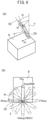
- FIG. 4(a) is a schematic perspective view showing a lead angle and a tilt angle
- FIG. 4(b) is a schematic plan view showing the tilt angle.
- the lead angle ⁇ l represents the angle between a line n perpendicular to a surface 8 to be machined and the central axis Ot of the tool T.
- the tilt angle ⁇ t represents the angle between the moving direction m of the tool T and the central axis Ot of the tool when viewed from the direction of the line n perpendicular to the surface 8 to be machined.
- the present inventors machined the surface 8 by moving the tool T along the direction m at various tilt angles ⁇ t, and measured the surface roughness Ra of the surface 8 and the cutting force applied to the tool T at each tilt angle ⁇ t.
- the lead angle ⁇ l was fixed at 30°.
- a general lollipop mill having a substantially spherical tip shape was used.
- FIG. 5 is a graph showing the relationship of tilt angle with surface roughness and cutting force.
- the horizontal axis represents the tilt angle
- the vertical axis represents the cutting force (scale on the left side) and surface roughness (arithmetic mean roughness, scale on the right side).
- the bar graph indicates surface roughness Ra
- the solid line indicates the radial cutting force fr
- the broken line indicates the axial cutting force fa.
- the surface roughness Ra is small and constant in the tilt angle ⁇ t range of 120° to 240°, and no vibrations are generated in this range. Further, in this range, the cutting force fr in the radial direction is also low, and it is presumed that the vibration is reduced as a result.
- the present inventors have conceived to apply this result to the machining of the flow path 4 described above.
- the tool T when a flow path 4 is machined by the tool T, the tool T is generally arranged so that the central axis Ot of the tool T is substantially parallel to the inner surface 7 of the hole and the tip of the tool T leads in the movement direction.
- the tilt angle ⁇ t it is necessary that the tool T machine the inner surface 7 of the hole only when the tool T moves from the apertures 5, 6 toward the interior of the hole.
- the present inventors have conceived of moving the tool T from the apertures 5, 6 toward the interior of the hole to machine the inner surface 7, then returning the tool T to the apertures 5, 6, and moving the tool T along the apertures 5, 6 at a predetermined pick feed P, and repeating these operations.
- vibration of the tool T may be further reduced by using a tool T which can reduce the cutting force fr in the radial direction.
- the tip of the cutting edge mainly receives the cutting force (feed component force).
- the present inventors have conceived to reduce the radial cutting force by making the shape of this portion easy to receive the cutting force (feed component force) in the axial direction.
- FIG. 6(a) is a schematic side view showing a tool according to an embodiment
- FIG. 6(b) is an enlarged cross-sectional view of portion D
- FIG. 6(c) is an enlarged view of portion D.
- the contour is drawn when the tool T is rotated around the central axis Ot (the same applies to FIGS. 7(a) and 8(a) , which are described later).
- the tool T includes a shaft-shaped tool body 11 and a tip 12.
- the tool T can be an integral body.
- the shaft-shaped tool body 11 extends along the central axis Ot of the tool.
- the shaft-shaped tool body 11 has a first end 11a for attachment to the spindle 60 of the machining center 100 and a second end 11b opposite to the first end 11a.
- the tip 12 is connected to the second end 11b of the shaft-shaped tool body 11.
- the tip 12 has a central part 13 and a plurality of blade parts 14.
- the central part 13 is located on the central axis Ot.
- the central part 13 includes a tip surface 17 of the tool T.
- the tip surface 17 is a flat surface.
- the tip surface 17 does not include the cutting edge.
- the blade parts 14 protrude radially outward from the central part 13.
- the tool T includes four blade parts 14 along the circumferential direction.
- the cutting edges of the blade parts 14 each include a main cutting edge 15 and a sub cutting edge 16.
- the main cutting edge 15 is adjacent to the tip surface 17.
- the main cutting edge 15 faces the direction away from the shaft-shaped tool body 11 in the direction parallel to the central axis Ot
- the sub cutting edge 16 faces the shaft-shaped tool body 11 in the direction parallel to the central axis Ot.
- the main cutting edge 15 and the sub cutting edge 16 are linear.
- the angle ⁇ 1 between the main cutting edge 15 and the central axis Ot is 150°.
- half of the cutting force (feed component force) applied to the main cutting edge 15 is converted into a cutting force in the axial direction (when the lead angle is 90° and the tilt angle is 180°). Therefore, the cutting force in the radial direction can be reduced.
- the angle between the main cutting edge 15 and the sub cutting edge 16 is, for example, approximately 90°.
- the corners between the main cutting edge 15 and the sub cutting edge 16 are rounded.
- FIG. 7(a) is a schematic side view showing a tool according to another embodiment
- FIG. 7(b) is an enlarged cross-sectional view of portion E
- FIG. 7(c) is an enlarged view of portion E.
- the embodiment of FIG. 7 differs from the embodiment of FIG. 6 in that the shape of the blade part 14 is different. Other points may be the same as those of the embodiment of FIG. 6 .
- the main cutting edge 15 of the present embodiment includes a linear portion on the inner side in the radial direction and an arcuate portion on the outer side in the radial direction.
- the sub cutting edge 16 includes a radial outer arcuate portion continuous with the arcuate portion of the main cutting edge 15, and a radial inner linear portion.
- the linear portion of the main cutting edge 15 is perpendicular to the central axis Ot.
- the angle ⁇ 1 between the linear portion of the main cutting edge 15 and the central axis Ot is 90°.
- the cutting force (feed component force) applied to the linear portion of the main cutting edge 15 is in the axial direction (when the lead angle is 90° and the tilt angle is 180°).
- the cutting force in the radial direction can be reduced.
- the portion from the central axis Ot to 30° about the center of the arc is formed by a contour (tangent line) forming an angle of 90° to 150° relative to the central axis Ot.
- the cutting force in the radial direction can be reduced.
- the linear portion of the sub cutting edge 16 forms an angle of, for example, approximately 30° relative to the central axis Ot.
- FIG. 8(a) is a schematic side view showing a tool according to yet another embodiment
- FIG. 8(b) is an enlarged cross-sectional view of portion F
- FIG. 8(c) is an enlarged view of portion F.
- the embodiment of FIG. 8 differs from the embodiment of FIG. 6 in that the tip surface 17 of the tool T is a curved surface (concave surface) and the shape of the blade part 14 is different. The other points may be the same as those of the embodiment of FIG. 6 .
- the main cutting edge 15 and the sub cutting edge 16 are linear.
- the angle ⁇ 1 between the main cutting edge 15 and the central axis Ot is 60°.
- most of the cutting force (feed component force) applied to the main cutting edge 15 is converted in the axial direction (when the lead angle is 90° and the tilt angle is 180°). Therefore, the cutting force in the radial direction can be reduced.
- the angle between the main cutting edge 15 and the sub cutting edge 16 is, for example, approximately 30°.
- the corners between the main cutting edge 15 and the sub cutting edge 16 are rounded.
- FIG. 9 is a schematic diagram showing a pick feed calculation method, and shows a tool T which machines the surface 8 with a lead angle ⁇ l of 90° and a tilt angle ⁇ t of 180°.
- the pick feed P is in the right direction.
- R represents the radius between the central axis Ot of the tool T and the outermost diameter of the blade part 14, and H represents the cusp height (the height of the convex portion remaining on the surface 8).
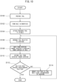
- FIG. 10 is a flowchart showing a machining method according to an embodiment.
- the operation of the machining center 100 shown below may be executed according to, for example, an NC program, or may be performed by an operator.
- the operator prepares a tool (second tool) T as described above (step S100). The details of step S100 will be described later.
- the machining center 100 forms a hole (lower hole) in the workpiece W with a first tool such as a drill (step S102).
- a first tool such as a drill
- the first tool is removed from the spindle 60 by an automatic tool changer (not illustrated) or by the operator, and the prepared second tool T is attached to the spindle 60 (step S104).
- the machining center 100 next arranges the tool T at a predetermined tilt angle ⁇ t in the range of 120° to 240° (for example, 180°) and a predetermined lead angle ⁇ l greater than 0° and less than or equal to 90° (for example, 90°) relative to the aperture 5 formed in the outer circumference of the workpiece W (step S106).
- the tool T may be in contact with or separated from the inner surface 7 of the hole.
- the machining center 100 moves the tool T along the inner surface 7 from the aperture 5 toward the interior of the hole to machine the inner surface 7 (step S108).
- the machining center 100 continues the machining to a predetermined depth.
- the machining center 100 next returns the tool T from the interior of the hole toward the aperture 5 in a state in which the tool T is separated from the inner surface 7 of the hole (step S110). For example, the machining center 100 may return the tool T to the position where the tool T was arranged in step S 106.
- the machining center 100 Until the position of the predetermined pick feed specified by the machine program is reached (step S112), the machining center 100 imparts a pick feed P calculated by the above formula (2) to the tool T, moves it along the peripheral edge of the aperture 5 (step S114), and repeats steps S106 to S110.
- the machining center 100 ends the series of operations.
- the machining center 100 may perform the same operation as described above from the aperture 6 on the inner circumference using the same tool T (or a different tool).
- step S100 in which the tool is prepared will be described.
- FIGS. 11(a) to 11(d) are schematic views showing the steps for preparing the tool.
- Step S100 in which the tool is prepared may be executed, for example, in CAD by an operator or in accordance with a program.
- the shape of the hole (lower hole) formed in step S102 is acquired.
- a remaining part 9 which was not machined by the first tool remains in the hole.
- the region 9a to be machined by the tool inserted from the aperture 5 and the region 9b to be machined by the tool inserted from the aperture 6 are determined.
- the tool to be inserted from the aperture 5 is prepared.
- the tool to be inserted from the aperture 6 may be prepared by the same method.
- the shape of the tip 12 of the tool T is determined based on the shape of the aperture 5. For example, the shape of the tip 12 is determined so that the tip 12 does not interfere with the aperture 5 when the tip 12 is arranged relative to the aperture 5 at a predetermined tilt angle (for example, 180°) and lead angle (for example 90°).
- a predetermined tilt angle for example, 180°
- lead angle for example 90°
- the tip 12 is arranged at the deepest position in the hole which the tip 12 can reach.
- the tip 12 is arranged so as to contact the deepest part of the region 9a.
- the shape of the shaft-shaped tool body 11 is determined so as not to interfere with the inner surface 7 and so as to maximize the thickness thereof. At this time, the tilt angle and the lead angle may be adjusted. Furthermore, when the determined tool T is moved from the aperture 5 toward the interior of the hole along the inner surface 7 in CAD, it may be determined whether or not portions of the tool T other than the cutting edge interfere with the inner surface 7. If interference occurs, the operator may adjust the shape of the shaft-shaped tool body 11.
- the main cutting edge 15 adjacent to the tip surface 17 of the tool mainly receives the cutting force (feed component force).
- the main cutting edge 15 includes a contour forming an angle of 30° to 150° relative to the central axis Ot.
- the inner surface 7 of the hole is machined only when the tool T moves inward from the aperture 5 of the hole. Furthermore, the tilt angle ⁇ t is set to 120° to 240°.
- Step S100 includes determining the shape of the tip 12 based on the shape of the aperture 5 of the hole, and determining the shape of the shaft-shaped tool body 11 so as not to interfere with the inner surface 7 and when the tip 12 is arranged at the deepest position in the hole which the tip 12 can reach and so as to maximize the thickness thereof.
- the shape of the tool T can be easily determined.
- step S106 includes setting the predetermined tilt angle ⁇ t and lead angle ⁇ l, and the pick feed P of step (vi) is calculated by formula (2) above.
- the desired cusp height surface roughness
- the desired surface roughness can be obtained by using the pick feed P obtained with formula (2) in step S114.
- each tool T shown in FIGS. 6 to 8 is used.
- another general tool for example, a lollipop mill
Landscapes
- Engineering & Computer Science (AREA)
- Mechanical Engineering (AREA)
- General Engineering & Computer Science (AREA)
- Milling Processes (AREA)
- Structures Of Non-Positive Displacement Pumps (AREA)
Applications Claiming Priority (2)
| Application Number | Priority Date | Filing Date | Title |
|---|---|---|---|
| JP2020064561A JP7121770B2 (ja) | 2020-03-31 | 2020-03-31 | 切削工具及びワークの加工方法 |
| PCT/JP2021/013983 WO2021201153A1 (ja) | 2020-03-31 | 2021-03-31 | 切削工具及びワークの加工方法 |
Publications (2)
| Publication Number | Publication Date |
|---|---|
| EP4129544A1 true EP4129544A1 (de) | 2023-02-08 |
| EP4129544A4 EP4129544A4 (de) | 2024-06-05 |
Family
ID=77928559
Family Applications (1)
| Application Number | Title | Priority Date | Filing Date |
|---|---|---|---|
| EP21781082.9A Pending EP4129544A4 (de) | 2020-03-31 | 2021-03-31 | Schneidinstrument und verfahren zum bearbeiten von werkstücken |
Country Status (5)
| Country | Link |
|---|---|
| US (1) | US12358059B2 (de) |
| EP (1) | EP4129544A4 (de) |
| JP (1) | JP7121770B2 (de) |
| CN (1) | CN115243815A (de) |
| WO (1) | WO2021201153A1 (de) |
Family Cites Families (19)
| Publication number | Priority date | Publication date | Assignee | Title |
|---|---|---|---|---|
| DE3603582C1 (de) * | 1986-02-06 | 1987-03-05 | Bayerische Motoren Werke Ag | Verfahren zur spanabhebenden Bearbeitung eines in einem Gussteil angeordneten Kanals |
| DE3816674A1 (de) * | 1988-05-17 | 1989-11-23 | Klein Schanzlin & Becker Ag | Verfahren zur herstellung eines kreiselpumpenlaufrades |
| JP2001328018A (ja) * | 2000-05-23 | 2001-11-27 | Mitsubishi Heavy Ind Ltd | 窓穴形成用切削工具、及び、窓穴形成用切削方法 |
| DE10219012B4 (de) * | 2002-04-27 | 2004-11-04 | Mtu Aero Engines Gmbh | Fräsverfahren |
| ITMI20021876A1 (it) * | 2002-09-03 | 2004-03-04 | Nuovo Pignone Spa | Procedimento migliorato per realizzare un rotore di un |
| DE10330831A1 (de) * | 2003-07-08 | 2005-02-10 | Mtu Aero Engines Gmbh | Fräsverfahren zur Fertigung von Bauteilen |
| DE102008010252A1 (de) * | 2008-02-20 | 2009-08-27 | Rolls-Royce Deutschland Ltd & Co Kg | Verfahren und Werkzeug zur Annulusbearbeitung eines Gasturbinenrotors mit integral angeformten Schaufeln |
| CN101708559B (zh) * | 2009-12-10 | 2011-03-02 | 西北工业大学 | 闭式整体叶盘五坐标插铣加工方法 |
| KR20120106989A (ko) * | 2009-12-22 | 2012-09-27 | 누보 피그노네 에스피에이 | 밀 및 사용 방법 |
| CN103038010B (zh) * | 2010-06-28 | 2015-08-19 | 野田金型有限会社 | 切削弯头及其制造方法 |
| JP2013035101A (ja) * | 2011-08-08 | 2013-02-21 | Honda Motor Co Ltd | リーマ |
| US9011051B2 (en) * | 2012-04-12 | 2015-04-21 | Lockheed Martin Corporation | Multi-spindle milling |
| CN102722137A (zh) * | 2012-06-29 | 2012-10-10 | 沈阳工业大学 | 直纹面叶轮五坐标插铣加工方法 |
| JP6395946B2 (ja) * | 2015-09-28 | 2018-09-26 | 三菱電機株式会社 | スクリューロータの加工方法、加工装置及び加工用工具並びにスクリュー圧縮機の製造方法 |
| US10994347B2 (en) | 2016-09-05 | 2021-05-04 | Mitsubishi Heavy Industries Compressor Corporation | Method for manufacturing centrifugal rotary machine and method for manufacturing impeller thereof |
| AT15965U1 (de) * | 2017-06-06 | 2018-10-15 | Ceratizit Austria Gmbh | Fräsverfahren |
| CN111542409B (zh) * | 2017-12-13 | 2023-04-04 | 株式会社牧野铣床制作所 | 铣刀以及工件加工方法 |
| WO2019168070A1 (ja) | 2018-02-28 | 2019-09-06 | ダイキン工業株式会社 | 加工品の製造方法、工具経路計算方法、加工品、及びインペラー |
| JP7075281B2 (ja) * | 2018-05-17 | 2022-05-25 | 大同マシナリー株式会社 | 四角ボックス柱の製造方法 |
-
2020
- 2020-03-31 JP JP2020064561A patent/JP7121770B2/ja active Active
-
2021
- 2021-03-31 US US17/904,936 patent/US12358059B2/en active Active
- 2021-03-31 CN CN202180019478.7A patent/CN115243815A/zh active Pending
- 2021-03-31 WO PCT/JP2021/013983 patent/WO2021201153A1/ja not_active Ceased
- 2021-03-31 EP EP21781082.9A patent/EP4129544A4/de active Pending
Also Published As
| Publication number | Publication date |
|---|---|
| CN115243815A (zh) | 2022-10-25 |
| EP4129544A4 (de) | 2024-06-05 |
| JP7121770B2 (ja) | 2022-08-18 |
| JP2021160040A (ja) | 2021-10-11 |
| US12358059B2 (en) | 2025-07-15 |
| US20230088133A1 (en) | 2023-03-23 |
| WO2021201153A1 (ja) | 2021-10-07 |
Similar Documents
| Publication | Publication Date | Title |
|---|---|---|
| US8286348B2 (en) | Method of manufacturing and refinishing integrally bladed rotors | |
| JP5646623B2 (ja) | 削り出しエルボとその製造方法 | |
| KR0174275B1 (ko) | 에어포일의 가공 방법 | |
| US8701530B2 (en) | Method of cutting thin-walled material | |
| US10012976B2 (en) | Method for machining the trailing edge of a turbine engine blade | |
| WO2011122621A1 (ja) | 工具軌跡生成装置、工具軌跡算出方法および工具軌跡生成プログラム | |
| CN115055744B (zh) | 一种基于数控机床的圆弧凹槽铣加工方法及应用 | |
| US6449529B1 (en) | Process for contour machining of metal blocks | |
| CN108406233A (zh) | 不规则壳体构件内腔底部环形槽的加工方法 | |
| CN117709024A (zh) | 一种航空精锻叶片工作面角度偏差的补偿方法 | |
| EP2540424A2 (de) | Sphärisches Schneidegerät und Verfahren zur maschinellen Bearbeitung eines gekrümmten Schlitzes | |
| JP2010269416A (ja) | 削り出しエルボの製造方法 | |
| EP4129544A1 (de) | Schneidinstrument und verfahren zum bearbeiten von werkstücken | |
| JP4183058B2 (ja) | 翼の切削方法 | |
| ZA200205855B (en) | A process for contour control machining of metal blocks. | |
| CN111922362B (zh) | 手表壳体加工方法及手表壳体 | |
| CN110788411B (zh) | 一种主轴叶根榫槽齿型的底弧、粗齿形加工刀具及方法 | |
| JP2001277015A (ja) | テーパ穴加工方法およびテーパ穴加工用工具 | |
| CN116871571B (zh) | 一种整体叶盘内花键的铣加工方法 | |
| CN218745101U (zh) | 一种立铣刀 | |
| JP3014110B2 (ja) | スクロール部材の製造方法 | |
| JPWO2019106844A1 (ja) | デフケース加工用の刃具、デフケースの加工機及びデフケースの加工方法 | |
| JPH021604B2 (de) | ||
| JP2000094270A (ja) | 鏡面加工方法 | |
| CN117696947A (zh) | 一种变径孔加工装置及方法 |
Legal Events
| Date | Code | Title | Description |
|---|---|---|---|
| STAA | Information on the status of an ep patent application or granted ep patent |
Free format text: STATUS: THE INTERNATIONAL PUBLICATION HAS BEEN MADE |
|
| PUAI | Public reference made under article 153(3) epc to a published international application that has entered the european phase |
Free format text: ORIGINAL CODE: 0009012 |
|
| STAA | Information on the status of an ep patent application or granted ep patent |
Free format text: STATUS: REQUEST FOR EXAMINATION WAS MADE |
|
| 17P | Request for examination filed |
Effective date: 20220906 |
|
| AK | Designated contracting states |
Kind code of ref document: A1 Designated state(s): AL AT BE BG CH CY CZ DE DK EE ES FI FR GB GR HR HU IE IS IT LI LT LU LV MC MK MT NL NO PL PT RO RS SE SI SK SM TR |
|
| DAV | Request for validation of the european patent (deleted) | ||
| DAX | Request for extension of the european patent (deleted) | ||
| A4 | Supplementary search report drawn up and despatched |
Effective date: 20240507 |
|
| RIC1 | Information provided on ipc code assigned before grant |
Ipc: F04D 29/28 20060101ALI20240430BHEP Ipc: F04D 29/22 20060101ALI20240430BHEP Ipc: B23C 5/12 20060101ALI20240430BHEP Ipc: B23C 3/18 20060101AFI20240430BHEP |