EP4122643B1 - Bohrstangenwerkzeugwechsler und bohrstangenwerkzeugwechselverfahren damit - Google Patents
Bohrstangenwerkzeugwechsler und bohrstangenwerkzeugwechselverfahren damit Download PDFInfo
- Publication number
- EP4122643B1 EP4122643B1 EP20927746.6A EP20927746A EP4122643B1 EP 4122643 B1 EP4122643 B1 EP 4122643B1 EP 20927746 A EP20927746 A EP 20927746A EP 4122643 B1 EP4122643 B1 EP 4122643B1
- Authority
- EP
- European Patent Office
- Prior art keywords
- magazine
- tool
- boring bar
- spindle
- exchanging
- Prior art date
- Legal status (The legal status is an assumption and is not a legal conclusion. Google has not performed a legal analysis and makes no representation as to the accuracy of the status listed.)
- Active
Links
Images


Classifications
-
- B—PERFORMING OPERATIONS; TRANSPORTING
- B23—MACHINE TOOLS; METAL-WORKING NOT OTHERWISE PROVIDED FOR
- B23Q—DETAILS, COMPONENTS, OR ACCESSORIES FOR MACHINE TOOLS, e.g. ARRANGEMENTS FOR COPYING OR CONTROLLING; MACHINE TOOLS IN GENERAL CHARACTERISED BY THE CONSTRUCTION OF PARTICULAR DETAILS OR COMPONENTS; COMBINATIONS OR ASSOCIATIONS OF METAL-WORKING MACHINES, NOT DIRECTED TO A PARTICULAR RESULT
- B23Q3/00—Devices holding, supporting, or positioning work or tools, of a kind normally removable from the machine
- B23Q3/155—Arrangements for automatic insertion or removal of tools, e.g. combined with manual handling
- B23Q3/157—Arrangements for automatic insertion or removal of tools, e.g. combined with manual handling of rotary tools
- B23Q3/15713—Arrangements for automatic insertion or removal of tools, e.g. combined with manual handling of rotary tools a transfer device taking a single tool from a storage device and inserting it in a spindle
- B23Q3/1572—Arrangements for automatic insertion or removal of tools, e.g. combined with manual handling of rotary tools a transfer device taking a single tool from a storage device and inserting it in a spindle the storage device comprising rotating or circulating storing means
- B23Q3/15722—Rotary discs or drums
-
- B—PERFORMING OPERATIONS; TRANSPORTING
- B23—MACHINE TOOLS; METAL-WORKING NOT OTHERWISE PROVIDED FOR
- B23Q—DETAILS, COMPONENTS, OR ACCESSORIES FOR MACHINE TOOLS, e.g. ARRANGEMENTS FOR COPYING OR CONTROLLING; MACHINE TOOLS IN GENERAL CHARACTERISED BY THE CONSTRUCTION OF PARTICULAR DETAILS OR COMPONENTS; COMBINATIONS OR ASSOCIATIONS OF METAL-WORKING MACHINES, NOT DIRECTED TO A PARTICULAR RESULT
- B23Q3/00—Devices holding, supporting, or positioning work or tools, of a kind normally removable from the machine
- B23Q3/155—Arrangements for automatic insertion or removal of tools, e.g. combined with manual handling
- B23Q3/1552—Arrangements for automatic insertion or removal of tools, e.g. combined with manual handling parts of devices for automatically inserting or removing tools
- B23Q3/15526—Storage devices; Drive mechanisms therefor
- B23Q3/15534—Magazines mounted on the spindle
-
- B—PERFORMING OPERATIONS; TRANSPORTING
- B23—MACHINE TOOLS; METAL-WORKING NOT OTHERWISE PROVIDED FOR
- B23Q—DETAILS, COMPONENTS, OR ACCESSORIES FOR MACHINE TOOLS, e.g. ARRANGEMENTS FOR COPYING OR CONTROLLING; MACHINE TOOLS IN GENERAL CHARACTERISED BY THE CONSTRUCTION OF PARTICULAR DETAILS OR COMPONENTS; COMBINATIONS OR ASSOCIATIONS OF METAL-WORKING MACHINES, NOT DIRECTED TO A PARTICULAR RESULT
- B23Q3/00—Devices holding, supporting, or positioning work or tools, of a kind normally removable from the machine
- B23Q3/155—Arrangements for automatic insertion or removal of tools, e.g. combined with manual handling
- B23Q3/15506—Arrangements for automatic insertion or removal of tools, e.g. combined with manual handling the tool being inserted in a tool holder directly from a storage device (without transfer device)
-
- B—PERFORMING OPERATIONS; TRANSPORTING
- B23—MACHINE TOOLS; METAL-WORKING NOT OTHERWISE PROVIDED FOR
- B23B—TURNING; BORING
- B23B29/00—Holders for non-rotary cutting tools; Boring bars or boring heads; Accessories for tool holders
- B23B29/02—Boring bars
Definitions
- the present invention relates to an apparatus for exchanging a tool of a boring bar and a method of exchanging a tool of a boring bar using the same. More particularly, the present invention relates to an apparatus for exchanging a tool installed at a front end of a long boring bar to machine a workpiece, and a method of exchanging a tool of a boring bar using the apparatus.
- a boring machine may be used for precisely machining a hole of a long workpiece.
- the boring machine may include a boring bar having a long length configured to enter into an inner surface of the hole of the long workpiece.
- a tool for machining the inner surface of the hole may be installed at a front end of the boring bar.
- the boring machine may include an apparatus for exchanging the tool for a new tool.
- the exchanging apparatus may have a structure commonly used with a spindle exchanging apparatus.
- the tool installed at the front end of the boring bar may have a size substantially the same as a size of a tool installed at a spindle.
- it may be required to reduce a weight of the tool at the front end of the boring bar.
- the tool at the spindle may not have a vibration damping function, the tool may have a large size so that the tool at the front end of the boring bar may also have a large size.
- a fixing force corresponding to the weight of the tool may be provided to the swing arm to prevent a falling of the tool.
- the fixing force may impact the boring bar having a long overhang in an exchanging process.
- the swing arm may have long X-Y axis strokes due to a distance difference between the spindle and the boring bar regardless of a size of the workpiece for the exchanging process. When a large space for the swing arm may not be secured, the size of the workpiece may be restricted due to interference between the workpiece and the spindle.
- JP 2003-080408 A discloses a machine tool comprising a boring bar supporting device.
- various standard tools to be demountable from a spindle and to be changed including a boring standard tool are constituted free to be demountably changed in the same way with respet to a boring bar main bodyto be supported and fixed on a boring bar installing part of a tool rest.
- a second tool supporting device free to demountably change the various standard tools from and a distal end of the boring bar main body is constituted such that a clamp working device provided with a first piston member to reciprocate in accordance with energizing force of a coil spring.
- the present invention provides an apparatus in accordance with claim 1 and a method in accordance with claim 9.
- an apparatus for exchanging a tool of a boring bar includes a magazine, a frame, a guide rail and an actuator.
- the magazine is configured to receive a plurality of the tools.
- the frame is arranged under the magazine.
- the guide is arranged on the frame.
- the magazine is movably connected to the guide rail.
- the actuator is configured to rotate the magazine.
- the magazine may include a rotation plate rotated by the actuator and a plurality of holders arranged on an outer surface of the rotation plate to hold the tools.
- the magazine may be rotated with respect to an axial direction of the boring bar.
- the guide rail may be extended in a direction substantially perpendicular to a rotation shaft of the magazine.
- the apparatus may further include a cylinder arranged at the frame to move the magazine along the guide rail.
- the apparatus may further include a bracket movably connected to the guide rail.
- the magazine may be rotatably connected to the bracket.
- the actuator may be installed at the bracket.
- the actuator may include a servo motor.
- the magazine may be arranged between a spindle exchanging apparatus and a spindle configured to fix a workpiece machined by the boring bar.
- arranging the magazine on the axial direction of the main shaft may include horizontally moving the magazine along a guide rail.
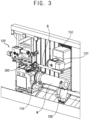
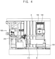
- the main shaft 110 may be horizontally arranged to fix a one end of a workpiece W.
- the workpiece W may have a long pipe shape having a hole.
- the vibration isolator 120 may support the other end of the workpiece W to prevent a vibration of the workpiece W.
- the spindle exchange apparatus 100 may be arranged on an end of the main shaft 110.
- the spindle exchange apparatus 100 may exchange the spindle 130 for a new spindle.
- the spindle exchange apparatus 100 may be arranged in a direction substantially parallel to an axial direction of the main shaft 110.
- the tool exchange apparatus 300 is configured to exchange a tool T installed at a front end of the boring bar B for a new tool T.
- the tool exchange apparatus 300 may be arranged between the main shaft 110 and the spindle exchange apparatus 100.
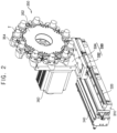
- the tool exchange apparatus 300 includes a frame 310, a guide rail 320, a bracket 330, a cylinder 340, a magazine 350 and an actuator 360.
- the frame 310 may be arranged between the main shaft 110 and the spindle exchange apparatus 100.
- the frame 310 may be extended in a direction substantially perpendicular to the axial direction of the main shaft 110.
- the guide rail 320 may be arranged on an upper surface of the frame 310.
- the guide rail 320 may be extended in the direction substantially perpendicular to the axial direction of the main shaft 110.
- the cylinder 340 may be installed at the upper surface of the frame 310.
- the cylinder 340 may provide the bracket 330, particularly, the slider 332 with a straight movement force in the direction substantially perpendicular to the axial direction of the main shaft 110.
- the slider 332 may be moved along the guide rail 320 by the straight movement force provided from the cylinder 340.
- the magazine 350 may be arranged on a first surface of the supporting plate 334 of the bracket 330, i.e., a front surface of the supporting plate 334 oriented toward the spindle 130.
- the magazine 350 may include a rotation plate 352 and a plurality of holder 354.
- the rotation plate 352 may be rotatably connected to the supporting plate 352 with respect to the axial direction of the main shaft 110.
- the holders 354 may be arranged on an outer surface of the rotation shaft 352.
- the holders 352 may be configured to hole the tools T.
- a holder 352 with the tool T to be exchanged among the holders 354 may be positioned at an exchange position by the rotation of the rotation plate 352.
- FIG. 5 is a flow chart illustrating a method of exchanging a tool of a boring bar using the apparatus in FIG. 1 .
- the tool T may be unclamped from the boring bar B.
- the boring bar B with the tool T may be moved forwardly to the exchange position.
- the magazine 350 may be moved to hold the tool T.
- the boring bar B may then be moved backwardly to unclamp the tool T from the boring bar B.
- step ST420 the cylinder 340 may move forwardly the bracket 330 along the guide rail 320 to position the bracket 330 on the axial direction of the main shaft 110.
- the actuator 360 may rotate the magazine 350 to locate the holder 352 with the tool T to be exchanged at the exchange position.
- the magazine configured to hold the tools may be arranged between the main shaft and the spindle exchanging apparatus to reduce a weight of the tool.
- a damper may have a vibration damping capacity to decrease an impulse generated in exchanging the tool. Further, the tool may be exchanged for the new tool regardless of a size of a workpiece.
Landscapes
- Engineering & Computer Science (AREA)
- Mechanical Engineering (AREA)
- Drilling And Boring (AREA)
- Automatic Tool Replacement In Machine Tools (AREA)
Claims (11)
- Vorrichtung (300) zum Wechseln eines Werkzeugs (T) einer Bohrstange (B), wobei die Vorrichtung (300) umfasst:ein Magazin (350), das so konfiguriert ist, dass es eine Mehrzahl der Werkzeuge (T) aufnimmt, die an einem vorderen Ende der Bohrstange (B) installiert werden sollen;einen Rahmen (310), der unter dem Magazin (350) angeordnet ist;eine Führungsschiene (320), die an dem Rahmen (310) angeordnet ist, wobeidas Magazin (350) mit der Führungsschiene (320) beweglich verbunden ist; undeinen Aktuator (360), der so konfiguriert ist, dass er sich mit dem Magazin (350) dreht.
- Vorrichtung (300) nach Anspruch 1, wobei das Magazin (350) umfasst:eine Drehplatte (352), die durch den Aktuator (360) gedreht wird;eine Mehrzahl von Haltern (354), die an einer äußeren Oberfläche der Drehplatte (352) angeordnet sind, um die Werkzeuge (T) zu halten.
- Vorrichtung (300) nach Anspruch 1, wobei das Magazin (350) mit Bezug auf eine axiale Richtung der Bohrstange (B) gedreht wird.
- Vorrichtung (300) nach Anspruch 1, wobei die Führungsschiene (320) in einer Richtung im Wesentlichen senkrecht zu einer Drehwelle des Magazins (350) angeordnet ist.
- Vorrichtung (300) nach Anspruch 1, weiterhin umfassend einen Zylinder (340), der an dem Rahmen (310) installiert ist, um das Magazin (350) entlang der Führungsschiene (320) zu bewegen.
- Vorrichtung (300) nach Anspruch 1, weiterhin umfassend eine Halterung (330), die mit der Führungsschiene (320) beweglich verbunden ist, wobei das Magazin drehbar mit der Halterung (330) verbunden ist und der Aktuator (360) an der Halterung (330) installiert ist.
- Vorrichtung (300) nach Anspruch 1, wobei der Aktuator (360) einen Servomotor umfasst.
- Bohrmaschine, umfassend:eine Hauptwelle (110), die horizontal angeordnet und so konfiguriert ist, dass sie ein Ende eines Werkstücks (W) fixiert;einen Schwingungsisolator (120), der so konfiguriert ist, dass er ein anderes Ende des Werkstücks (W) stützt;eine Spindel (130);ein Übertragungslager (150), das so konfiguriert ist, dass es die Spindel (130) überträgt;eine Bohrstange (B), die an einem unteren Ende des Übertragungslagers (150) fixiert und so konfiguriert ist, dass sie das Werkstück (W) bearbeitet;eine Spindelwechselvorrichtung (100), die an einem Ende der Hauptwelle (110) angeordnet und so konfiguriert ist, dass sie die Spindel (130) gegen eine neue Spindel (130) auswechselt; unddie Vorrichtung (300) nach Anspruch 1, wobei das Magazin (350) zwischen der Spindelwechselvorrichtung (100) und der Hauptwelle (110) angeordnet ist.
- Verfahren zum Wechseln eines Werkzeugs (T) einer Bohrstange (B), wobei das Verfahren umfasst:Anordnen eines Magazins (350), das so konfiguriert ist, dass es eine Mehrzahl von Haltern (354) zum Halten einer Mehrzahl der Werkzeuge (T) aufnimmt, in axialer Richtung der Hauptwelle (110) in einer Bohrmaschine;Drehen des Magazins (350), um einen Halter (354) mit einem neuen Werkzeug (T) unter den Haltern (354) an einer Wechselposition positionieren;Anordnen der Bohrstange (B) mit dem Werkzeug (T) an einer Vorderseite des Magazins (350); undAuswechseln des Werkzeugs (T) gegen das neue Werkzeug (T).
- Verfahren nach Anspruch 9, wobei ein Anordnen des Magazins (350) in axialer Richtung der Hauptwelle (110) das horizontale Bewegen des Magazins (350) entlang einer Führungsschiene (320) umfasst.
- Verfahren nach Anspruch 9, weiterhin umfassend das Zurückführen des Magazins (350) in seine ursprüngliche Position nach dem Auswechseln des Werkzeugs (T) gegen das neue Werkzeug (T).
Applications Claiming Priority (1)
| Application Number | Priority Date | Filing Date | Title |
|---|---|---|---|
| PCT/KR2020/003919 WO2021193986A1 (ko) | 2020-03-23 | 2020-03-23 | 보링 바의 툴 교환 장치 및 이를 이용한 보링 바의 툴 교환 방법 |
Publications (4)
| Publication Number | Publication Date |
|---|---|
| EP4122643A1 EP4122643A1 (de) | 2023-01-25 |
| EP4122643A4 EP4122643A4 (de) | 2023-12-20 |
| EP4122643B1 true EP4122643B1 (de) | 2025-01-22 |
| EP4122643C0 EP4122643C0 (de) | 2025-01-22 |
Family
ID=77890391
Family Applications (1)
| Application Number | Title | Priority Date | Filing Date |
|---|---|---|---|
| EP20927746.6A Active EP4122643B1 (de) | 2020-03-23 | 2020-03-23 | Bohrstangenwerkzeugwechsler und bohrstangenwerkzeugwechselverfahren damit |
Country Status (4)
| Country | Link |
|---|---|
| US (1) | US20230191548A1 (de) |
| EP (1) | EP4122643B1 (de) |
| CN (1) | CN115335188B (de) |
| WO (1) | WO2021193986A1 (de) |
Families Citing this family (2)
| Publication number | Priority date | Publication date | Assignee | Title |
|---|---|---|---|---|
| CN116141005B (zh) * | 2023-04-17 | 2023-08-18 | 池州中科裕华汽车科技有限公司 | 一种皮带轮数控加工中心 |
| JP7573096B1 (ja) | 2023-12-26 | 2024-10-24 | Dmg森精機株式会社 | 工具搬送装置、及び、加工システム |
Family Cites Families (31)
| Publication number | Priority date | Publication date | Assignee | Title |
|---|---|---|---|---|
| CH481717A (de) * | 1968-02-24 | 1969-11-30 | Mueller Max Brinker Maschf | Werkzeugmaschine ,insbesondere Drehmaschine |
| DE8421945U1 (de) * | 1984-07-23 | 1984-10-31 | Kastner, Hermann, Dipl.-Ing., 7140 Ludwigsburg | Teilbares werkzeug fuer die spanabhebende bearbeitung |
| JP2532663Y2 (ja) * | 1990-06-29 | 1997-04-16 | 三井精機工業株式会社 | ラインボーリングバの自動交換装置 |
| US6149561A (en) * | 1999-03-16 | 2000-11-21 | Unova Ip Corp | Machine and method for flexible line boring |
| JP2002307218A (ja) * | 2001-04-12 | 2002-10-23 | Toyoda Mach Works Ltd | 多径に対応可能な高速ボーリング軸頭 |
| JP3908495B2 (ja) * | 2001-09-10 | 2007-04-25 | ヤマザキマザック株式会社 | ボーリングバー支持装置、及び工作機械 |
| US7144355B2 (en) * | 2002-07-03 | 2006-12-05 | Toshiba Kikai Kabushiki Kaisha | Tool replacement method and nut driver for machine tools |
| JP4632344B2 (ja) * | 2003-12-18 | 2011-02-16 | 株式会社森精機製作所 | ボーリングバーマガジンを有する工作機械 |
| JP4342928B2 (ja) * | 2003-12-25 | 2009-10-14 | 株式会社森精機製作所 | 工作機械の工具交換装置 |
| DE102005043399B4 (de) * | 2005-09-08 | 2009-06-10 | Tixbo Tiefbohr-Center Gmbh & Co.Kg | Vorrichtung zur spanenden Bearbeitung mit automatischem Werkzeugwechsel sowie Verfahren zum automatischen Wechseln von Werkzeugen an der Vorrichtung zur spanenden Bearbeitung |
| KR100750594B1 (ko) * | 2006-10-26 | 2007-08-21 | 한국기계연구원 | 반원형상의 매거진이 부착된 이동형 암레스 atc 머시닝센터 |
| KR100779805B1 (ko) * | 2006-12-14 | 2007-11-27 | 두산인프라코어 주식회사 | 공구 매거진 구동과 연계된 atc 도어의 개폐장치 |
| JP5026884B2 (ja) * | 2007-08-04 | 2012-09-19 | 株式会社森精機製作所 | 自動工具交換装置を有する工作機械 |
| KR100938081B1 (ko) * | 2007-10-12 | 2010-01-21 | 현대위아 주식회사 | 매거진과 atc도어가 일체화된 구조를 갖는 엄브렐라타입 자동공구교환장치 |
| JP2009178804A (ja) * | 2008-01-31 | 2009-08-13 | Mori Seiki Co Ltd | ボーリングバーマガジンを有する工作機械およびボーリングバーマガジン |
| CN201346715Y (zh) * | 2009-01-24 | 2009-11-18 | 苏州江南电梯(集团)有限公司 | 具有复合式刀库的加工中心 |
| CN202556120U (zh) * | 2011-12-28 | 2012-11-28 | 南京宁庆数控机床制造有限公司 | 一种龙门加工中心后端面安装式刀库 |
| ITTV20120043A1 (it) * | 2012-03-21 | 2013-09-22 | Almerino Canuto | Dispositivo di cambio punte a cannone per forature profonde |
| TW201343284A (zh) * | 2012-04-23 | 2013-11-01 | Alex Tech Machinery Ind Co Ltd | 工具機深孔加工的複合式尾座裝置 |
| JP2015182139A (ja) * | 2014-03-20 | 2015-10-22 | 三菱重工業株式会社 | 工作機械 |
| CN104959865A (zh) * | 2015-04-29 | 2015-10-07 | 佛山市普拉迪数控科技有限公司 | 一种换刀精度高的斗笠刀库 |
| JP5956040B1 (ja) * | 2015-09-07 | 2016-07-20 | Dmg森精機株式会社 | 工作機械 |
| CN106914634A (zh) * | 2015-12-25 | 2017-07-04 | 茅保富 | 可调镗刀盘 |
| JP6886166B2 (ja) * | 2016-04-22 | 2021-06-16 | 中村留精密工業株式会社 | 工具交換装置及び交換方法 |
| KR101850759B1 (ko) * | 2016-12-19 | 2018-06-07 | 주식회사 스맥 | 공작기계 |
| EP3456466B1 (de) * | 2017-09-14 | 2022-04-06 | Rollomatic S.A. | Werkzeugmagazin und verfahren zum wechseln von werkzeugen |
| DE102017125316A1 (de) * | 2017-10-27 | 2019-05-02 | Moroff & Baierl Gmbh | Vorrichtung zum Austauschen eines Teils eines Werkzeugs und hohles Fräswerkzeug |
| KR20190083104A (ko) * | 2018-01-03 | 2019-07-11 | 두산공작기계 주식회사 | 공작기계의 툴 매거진 |
| KR102768668B1 (ko) * | 2019-03-05 | 2025-02-18 | 주식회사 디엔솔루션즈 | 보링 바의 툴 교환 장치 및 이를 이용한 보링 바의 툴 교환 방법 |
| KR102598071B1 (ko) * | 2019-03-08 | 2023-11-03 | 주식회사 디엔솔루션즈 | 자동공구교환장치와 이의 제어방법, 및 이를 포함하는 공작기계 |
| JP2023062629A (ja) * | 2021-10-21 | 2023-05-08 | 花王株式会社 | 油性化粧料 |
-
2020
- 2020-03-23 EP EP20927746.6A patent/EP4122643B1/de active Active
- 2020-03-23 WO PCT/KR2020/003919 patent/WO2021193986A1/ko not_active Ceased
- 2020-03-23 CN CN202080098990.0A patent/CN115335188B/zh active Active
- 2020-03-23 US US17/913,133 patent/US20230191548A1/en active Pending
Also Published As
| Publication number | Publication date |
|---|---|
| CN115335188B (zh) | 2024-06-18 |
| WO2021193986A1 (ko) | 2021-09-30 |
| EP4122643A4 (de) | 2023-12-20 |
| EP4122643C0 (de) | 2025-01-22 |
| CN115335188A (zh) | 2022-11-11 |
| US20230191548A1 (en) | 2023-06-22 |
| EP4122643A1 (de) | 2023-01-25 |
Similar Documents
| Publication | Publication Date | Title |
|---|---|---|
| US5172464A (en) | Machine tool | |
| US11167354B2 (en) | Machine tool, in particular lathe | |
| EP4122643B1 (de) | Bohrstangenwerkzeugwechsler und bohrstangenwerkzeugwechselverfahren damit | |
| EP2163334B2 (de) | Maschine mit einer Trommel mit Werkstückspindeln, die in der Längsachse der Trommel bewegbar sind | |
| JP2018001364A (ja) | 工作機械ユニット | |
| KR101796321B1 (ko) | 공작기계의 자동 공구 교환장치 | |
| KR102768668B1 (ko) | 보링 바의 툴 교환 장치 및 이를 이용한 보링 바의 툴 교환 방법 | |
| CN101508028B (zh) | 工作机械 | |
| JP4741351B2 (ja) | 小型旋盤 | |
| JP6525737B2 (ja) | 工作機械 | |
| JP5374195B2 (ja) | 工作機械 | |
| JP4560876B2 (ja) | 加工システム | |
| CN222175953U (zh) | 一种用于汽车减震器活塞生产线的自动加工装置 | |
| JP3249741B2 (ja) | 工作機械および工具交換装置 | |
| JP7466068B2 (ja) | 工具クランプ装置 | |
| US20240307971A1 (en) | Machine tool, in particular a lathe, and method for machining workpieces using a machine tool | |
| JP7733584B2 (ja) | 増設工具マガジン装置及び工作機械 | |
| JP6825153B1 (ja) | マガジンおよび工作機械 | |
| CN118478240A (zh) | 五轴加工设备 | |
| JP2008110425A (ja) | 工具マガジン及び工作機械 | |
| JPH06246514A (ja) | 自動旋盤 | |
| JPH10128637A (ja) | マトリックス型工具マガジンの工具搬送方法及びマトリックス型工具マガジン | |
| JPH0428496B2 (de) | ||
| JP2001198703A (ja) | 複合移動軸を備えた数値制御工作機械及びこの数値制御工作機械による加工方法 | |
| JPH1058261A (ja) | 工作機械 |
Legal Events
| Date | Code | Title | Description |
|---|---|---|---|
| STAA | Information on the status of an ep patent application or granted ep patent |
Free format text: STATUS: THE INTERNATIONAL PUBLICATION HAS BEEN MADE |
|
| PUAI | Public reference made under article 153(3) epc to a published international application that has entered the european phase |
Free format text: ORIGINAL CODE: 0009012 |
|
| STAA | Information on the status of an ep patent application or granted ep patent |
Free format text: STATUS: REQUEST FOR EXAMINATION WAS MADE |
|
| 17P | Request for examination filed |
Effective date: 20221020 |
|
| AK | Designated contracting states |
Kind code of ref document: A1 Designated state(s): AL AT BE BG CH CY CZ DE DK EE ES FI FR GB GR HR HU IE IS IT LI LT LU LV MC MK MT NL NO PL PT RO RS SE SI SK SM TR |
|
| DAV | Request for validation of the european patent (deleted) | ||
| DAX | Request for extension of the european patent (deleted) | ||
| A4 | Supplementary search report drawn up and despatched |
Effective date: 20231122 |
|
| RIC1 | Information provided on ipc code assigned before grant |
Ipc: B23B 29/02 20060101ALI20231116BHEP Ipc: B23Q 3/155 20060101AFI20231116BHEP |
|
| GRAP | Despatch of communication of intention to grant a patent |
Free format text: ORIGINAL CODE: EPIDOSNIGR1 |
|
| STAA | Information on the status of an ep patent application or granted ep patent |
Free format text: STATUS: GRANT OF PATENT IS INTENDED |
|
| INTG | Intention to grant announced |
Effective date: 20240903 |
|
| GRAS | Grant fee paid |
Free format text: ORIGINAL CODE: EPIDOSNIGR3 |
|
| GRAA | (expected) grant |
Free format text: ORIGINAL CODE: 0009210 |
|
| STAA | Information on the status of an ep patent application or granted ep patent |
Free format text: STATUS: THE PATENT HAS BEEN GRANTED |
|
| AK | Designated contracting states |
Kind code of ref document: B1 Designated state(s): AL AT BE BG CH CY CZ DE DK EE ES FI FR GB GR HR HU IE IS IT LI LT LU LV MC MK MT NL NO PL PT RO RS SE SI SK SM TR |
|
| REG | Reference to a national code |
Ref country code: GB Ref legal event code: FG4D |
|
| REG | Reference to a national code |
Ref country code: CH Ref legal event code: EP |
|
| REG | Reference to a national code |
Ref country code: IE Ref legal event code: FG4D |
|
| REG | Reference to a national code |
Ref country code: DE Ref legal event code: R096 Ref document number: 602020045382 Country of ref document: DE |
|
| U01 | Request for unitary effect filed |
Effective date: 20250122 |
|
| U07 | Unitary effect registered |
Designated state(s): AT BE BG DE DK EE FI FR IT LT LU LV MT NL PT RO SE SI Effective date: 20250129 |
|
| U20 | Renewal fee for the european patent with unitary effect paid |
Year of fee payment: 6 Effective date: 20250221 |
|
| PGFP | Annual fee paid to national office [announced via postgrant information from national office to epo] |
Ref country code: GB Payment date: 20250326 Year of fee payment: 6 |
|
| PG25 | Lapsed in a contracting state [announced via postgrant information from national office to epo] |
Ref country code: RS Free format text: LAPSE BECAUSE OF FAILURE TO SUBMIT A TRANSLATION OF THE DESCRIPTION OR TO PAY THE FEE WITHIN THE PRESCRIBED TIME-LIMIT Effective date: 20250422 |
|
| PG25 | Lapsed in a contracting state [announced via postgrant information from national office to epo] |
Ref country code: PL Free format text: LAPSE BECAUSE OF FAILURE TO SUBMIT A TRANSLATION OF THE DESCRIPTION OR TO PAY THE FEE WITHIN THE PRESCRIBED TIME-LIMIT Effective date: 20250122 |
|
| PG25 | Lapsed in a contracting state [announced via postgrant information from national office to epo] |
Ref country code: ES Free format text: LAPSE BECAUSE OF FAILURE TO SUBMIT A TRANSLATION OF THE DESCRIPTION OR TO PAY THE FEE WITHIN THE PRESCRIBED TIME-LIMIT Effective date: 20250122 |
|
| PG25 | Lapsed in a contracting state [announced via postgrant information from national office to epo] |
Ref country code: NO Free format text: LAPSE BECAUSE OF FAILURE TO SUBMIT A TRANSLATION OF THE DESCRIPTION OR TO PAY THE FEE WITHIN THE PRESCRIBED TIME-LIMIT Effective date: 20250422 Ref country code: IS Free format text: LAPSE BECAUSE OF FAILURE TO SUBMIT A TRANSLATION OF THE DESCRIPTION OR TO PAY THE FEE WITHIN THE PRESCRIBED TIME-LIMIT Effective date: 20250522 |
|
| PG25 | Lapsed in a contracting state [announced via postgrant information from national office to epo] |
Ref country code: HR Free format text: LAPSE BECAUSE OF FAILURE TO SUBMIT A TRANSLATION OF THE DESCRIPTION OR TO PAY THE FEE WITHIN THE PRESCRIBED TIME-LIMIT Effective date: 20250122 |
|
| PG25 | Lapsed in a contracting state [announced via postgrant information from national office to epo] |
Ref country code: GR Free format text: LAPSE BECAUSE OF FAILURE TO SUBMIT A TRANSLATION OF THE DESCRIPTION OR TO PAY THE FEE WITHIN THE PRESCRIBED TIME-LIMIT Effective date: 20250423 |
|
| PG25 | Lapsed in a contracting state [announced via postgrant information from national office to epo] |
Ref country code: SM Free format text: LAPSE BECAUSE OF FAILURE TO SUBMIT A TRANSLATION OF THE DESCRIPTION OR TO PAY THE FEE WITHIN THE PRESCRIBED TIME-LIMIT Effective date: 20250122 |
|
| PG25 | Lapsed in a contracting state [announced via postgrant information from national office to epo] |
Ref country code: MC Free format text: LAPSE BECAUSE OF FAILURE TO SUBMIT A TRANSLATION OF THE DESCRIPTION OR TO PAY THE FEE WITHIN THE PRESCRIBED TIME-LIMIT Effective date: 20250122 |
|
| PG25 | Lapsed in a contracting state [announced via postgrant information from national office to epo] |
Ref country code: CZ Free format text: LAPSE BECAUSE OF FAILURE TO SUBMIT A TRANSLATION OF THE DESCRIPTION OR TO PAY THE FEE WITHIN THE PRESCRIBED TIME-LIMIT Effective date: 20250122 |
|
| REG | Reference to a national code |
Ref country code: CH Ref legal event code: H13 Free format text: ST27 STATUS EVENT CODE: U-0-0-H10-H13 (AS PROVIDED BY THE NATIONAL OFFICE) Effective date: 20251023 |
|
| PG25 | Lapsed in a contracting state [announced via postgrant information from national office to epo] |
Ref country code: SK Free format text: LAPSE BECAUSE OF FAILURE TO SUBMIT A TRANSLATION OF THE DESCRIPTION OR TO PAY THE FEE WITHIN THE PRESCRIBED TIME-LIMIT Effective date: 20250122 |
|
| PLBE | No opposition filed within time limit |
Free format text: ORIGINAL CODE: 0009261 |
|
| STAA | Information on the status of an ep patent application or granted ep patent |
Free format text: STATUS: NO OPPOSITION FILED WITHIN TIME LIMIT |