EP4122641B1 - Walzmaschine zum zusammenbauen von wärmegeschnittenen profilen - Google Patents
Walzmaschine zum zusammenbauen von wärmegeschnittenen profilen Download PDFInfo
- Publication number
- EP4122641B1 EP4122641B1 EP22183366.8A EP22183366A EP4122641B1 EP 4122641 B1 EP4122641 B1 EP 4122641B1 EP 22183366 A EP22183366 A EP 22183366A EP 4122641 B1 EP4122641 B1 EP 4122641B1
- Authority
- EP
- European Patent Office
- Prior art keywords
- roller
- actuation means
- working
- advancement direction
- machine
- Prior art date
- Legal status (The legal status is an assumption and is not a legal conclusion. Google has not performed a legal analysis and makes no representation as to the accuracy of the status listed.)
- Active
Links
Images


Classifications
-
- B—PERFORMING OPERATIONS; TRANSPORTING
- B23—MACHINE TOOLS; METAL-WORKING NOT OTHERWISE PROVIDED FOR
- B23P—METAL-WORKING NOT OTHERWISE PROVIDED FOR; COMBINED OPERATIONS; UNIVERSAL MACHINE TOOLS
- B23P11/00—Connecting or disconnecting metal parts or objects by metal-working techniques not otherwise provided for
- B23P11/005—Connecting or disconnecting metal parts or objects by metal-working techniques not otherwise provided for by expanding or crimping
-
- B—PERFORMING OPERATIONS; TRANSPORTING
- B21—MECHANICAL METAL-WORKING WITHOUT ESSENTIALLY REMOVING MATERIAL; PUNCHING METAL
- B21D—WORKING OR PROCESSING OF SHEET METAL OR METAL TUBES, RODS OR PROFILES WITHOUT ESSENTIALLY REMOVING MATERIAL; PUNCHING METAL
- B21D47/00—Making rigid structural elements or units, e.g. honeycomb structures
- B21D47/04—Making rigid structural elements or units, e.g. honeycomb structures composite sheet metal profiles
-
- B—PERFORMING OPERATIONS; TRANSPORTING
- B21—MECHANICAL METAL-WORKING WITHOUT ESSENTIALLY REMOVING MATERIAL; PUNCHING METAL
- B21D—WORKING OR PROCESSING OF SHEET METAL OR METAL TUBES, RODS OR PROFILES WITHOUT ESSENTIALLY REMOVING MATERIAL; PUNCHING METAL
- B21D53/00—Making other particular articles
- B21D53/74—Making other particular articles frames for openings, e.g. for windows, doors, handbags
-
- E—FIXED CONSTRUCTIONS
- E06—DOORS, WINDOWS, SHUTTERS, OR ROLLER BLINDS IN GENERAL; LADDERS
- E06B—FIXED OR MOVABLE CLOSURES FOR OPENINGS IN BUILDINGS, VEHICLES, FENCES OR LIKE ENCLOSURES IN GENERAL, e.g. DOORS, WINDOWS, BLINDS, GATES
- E06B3/00—Window sashes, door leaves, or like elements for closing wall or like openings; Layout of fixed or moving closures, e.g. windows in wall or like openings; Features of rigidly-mounted outer frames relating to the mounting of wing frames
- E06B3/04—Wing frames not characterised by the manner of movement
- E06B3/263—Frames with special provision for insulation
- E06B3/26301—Frames with special provision for insulation with prefabricated insulating strips between two metal section members
- E06B3/26303—Frames with special provision for insulation with prefabricated insulating strips between two metal section members with thin strips, e.g. defining a hollow space between the metal section members
-
- E—FIXED CONSTRUCTIONS
- E06—DOORS, WINDOWS, SHUTTERS, OR ROLLER BLINDS IN GENERAL; LADDERS
- E06B—FIXED OR MOVABLE CLOSURES FOR OPENINGS IN BUILDINGS, VEHICLES, FENCES OR LIKE ENCLOSURES IN GENERAL, e.g. DOORS, WINDOWS, BLINDS, GATES
- E06B3/00—Window sashes, door leaves, or like elements for closing wall or like openings; Layout of fixed or moving closures, e.g. windows in wall or like openings; Features of rigidly-mounted outer frames relating to the mounting of wing frames
- E06B3/04—Wing frames not characterised by the manner of movement
- E06B3/263—Frames with special provision for insulation
- E06B3/26301—Frames with special provision for insulation with prefabricated insulating strips between two metal section members
- E06B3/26305—Connection details
-
- E—FIXED CONSTRUCTIONS
- E06—DOORS, WINDOWS, SHUTTERS, OR ROLLER BLINDS IN GENERAL; LADDERS
- E06B—FIXED OR MOVABLE CLOSURES FOR OPENINGS IN BUILDINGS, VEHICLES, FENCES OR LIKE ENCLOSURES IN GENERAL, e.g. DOORS, WINDOWS, BLINDS, GATES
- E06B3/00—Window sashes, door leaves, or like elements for closing wall or like openings; Layout of fixed or moving closures, e.g. windows in wall or like openings; Features of rigidly-mounted outer frames relating to the mounting of wing frames
- E06B3/04—Wing frames not characterised by the manner of movement
- E06B3/263—Frames with special provision for insulation
- E06B3/273—Frames with special provision for insulation with prefabricated insulating elements held in position by deformation of portions of the metal frame members
-
- B—PERFORMING OPERATIONS; TRANSPORTING
- B21—MECHANICAL METAL-WORKING WITHOUT ESSENTIALLY REMOVING MATERIAL; PUNCHING METAL
- B21D—WORKING OR PROCESSING OF SHEET METAL OR METAL TUBES, RODS OR PROFILES WITHOUT ESSENTIALLY REMOVING MATERIAL; PUNCHING METAL
- B21D39/00—Application of procedures in order to connect objects or parts, e.g. coating with sheet metal otherwise than by plating; Tube expanders
- B21D39/04—Application of procedures in order to connect objects or parts, e.g. coating with sheet metal otherwise than by plating; Tube expanders of tubes with tubes; of tubes with rods
-
- B—PERFORMING OPERATIONS; TRANSPORTING
- B23—MACHINE TOOLS; METAL-WORKING NOT OTHERWISE PROVIDED FOR
- B23P—METAL-WORKING NOT OTHERWISE PROVIDED FOR; COMBINED OPERATIONS; UNIVERSAL MACHINE TOOLS
- B23P19/00—Machines for simply fitting together or separating metal parts or objects, or metal and non-metal parts, whether or not involving some deformation; Tools or devices therefor so far as not provided for in other classes
- B23P19/04—Machines for simply fitting together or separating metal parts or objects, or metal and non-metal parts, whether or not involving some deformation; Tools or devices therefor so far as not provided for in other classes for assembling or disassembling parts
Definitions
- the present invention relates to a rolling machine for assembling heat-cut profiles according to the preamble of claim 1.
- a rolling machine is known from WO 2017/085684 A1 .
- Heat-cut profiles are known which are generally constituted by at least two profile portions made of aluminum, so-called “shells,” obtained by extrusion and connected to each other by interposition of one or more elongated connecting partitions, so-called “strips,” made of thermally insulating material of the type of polyamide or other plastic material.
- Each profile portion is provided with at least one longitudinal slot, which is bounded by two opposing ribs, so-called “hammers,” one of which is deformable.
- the two profile portions are positioned side-by-side with their respective slots facing each other in pairs to define at least one receptacle for a corresponding strip with the associated deformable ribs arranged on the same side of the strip.
- Such profiles are widely used in the field of the production of energy-saving windows and doors, in which the two profile portions are positioned one toward the inside and one toward the outside of the room in which the window or door is assembled, with the interposition of an air space defined between said profile portions and the strips which acts as a thermal barrier.
- these steps are carried out in series while the semi-finished manufactured article is transferred by known conveyance systems through the various working stations.
- the rolling machine is crossed by the pre-assembled semi-finished manufactured article, which is moved along a substantially horizontal advancement direction, with the profile portions arranged one above the other and with the deformable ribs for clamping the strips exposed and accessible from opposite sides of the advancement direction.
- Such rolling machines are therefore provided on each side of the advancement direction with a working assembly which comprises upper rollers and lower rollers adapted to apply a pressure on respective deformable ribs so as to obtain the final assembly of the invention.
- One known type of rolling machine provides, on each side of the advancement direction, for the presence of a working assembly comprising a plurality of rolling assemblies, each constituted by an upper roller and a lower roller which rotate about a same substantially vertical axis of rotation and are supported in rotation by respective mutually coaxial shafts.
- a working assembly comprising a plurality of rolling assemblies, each constituted by an upper roller and a lower roller which rotate about a same substantially vertical axis of rotation and are supported in rotation by respective mutually coaxial shafts.
- the lower roller is supported in rotation by a hollow shaft, inside which a coaxial shaft for supporting the corresponding upper roller is inserted slidingly.
- the work elevation of the upper roller with respect to the corresponding lower roller can be adjusted by actuating the sliding of the associated supporting shaft along the hollow shaft.
- the supporting shaft of the upper roller must necessarily have a diameter that is smaller than that of the hollow shaft in which it is inserted slidingly and is positioned with an end portion which protrudes in a cantilever manner from said hollow shaft.
- the supporting shaft of the upper roller is subjected to radial loads due to the contact reaction of the semi-finished product being worked, which tend to subject it to bending stresses, and therefore the length of the supporting shaft section that protrudes in a cantilever manner from the hollow shaft must be limited, so that excessive deformations, which would adversely affect the work performed, do not occur.
- a rolling machine which provides, on each side of the working direction, a working assembly comprising a plurality of upper rollers and a plurality of lower rollers provided with respective support, adjustment and rotational actuation means, which are arranged in pairs coaxially in a vertical direction.
- the support, adjustment and rotational actuation assembly for the upper rollers is arranged above the one of the lower rollers and has such a space as to penalize accessibility to the working area.
- the aim of the present invention is to eliminate the drawbacks mentioned above of the background art by devising a rolling machine for assembling heat-cut profiles which has wide intervals for adjustment of the working position of the rollers, so as to facilitate the arrangement and support of the pre-assembled manufactured article being worked regardless of its shape, dimensions and weight.
- an object of the present invention is to keep the work area easily accessible in order to facilitate the assembly of the fixtures for supporting the pre-assembled manufactured article being worked.
- a further object of the present invention is to allow the working of profiles which incorporate strips of different heights or of the offset type, as well as with a double heat bridge.
- Not least object of the present invention is to provide a structure that is simple, relatively easy to provide in practice, of assured application, effective in operation, and of relatively low cost.
- a rolling machine for assembling heat-cut profiles is generally designated by the reference numeral 1.
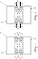
- a heat-cut profile P which is shown by way of example in Figures 1 and 2 , is composed of a first profile portion S1 and a second profile portion S2 constituted by respective extruded bars made of aluminum, each of which is provided in the peripheral region with at least one longitudinal slot C which is delimited by a pair of opposite ribs N and N'.
- the profile portions S1 and S2 are arranged mutually side-by-side with their slots C facing each other so as to define at least one receptacle for a corresponding connecting partition B, constituted by an elongated strip made of thermally insulating material of the type of polyamide or other plastic material.
- the cross-section of the profile portions S1 and S2 and of the profile P, which is composed by them, can have multiple shapes depending on the requirements of the case.
- Each profile portion S1 or S2 has the corresponding protruding ribs N and the remaining portion of the cross-section all comprised in a half-plane delimited by the outline of the plane of arrangement of said ribs in order to allow the assembly of the profile.
- each profile portion S1 or S2 can provide for one or more parallel slots C so as to define one or more receptacles of respective connecting partitions B.
- the illustrated embodiment shows a profile P provided with two connecting partitions B, the profile portions S1 and S2 of which are each provided with two slots C, so that by juxtaposing the two profile portions S1 and S2 with the associated slots C facing each other in pairs, two seats for accommodating respective connecting partitions B are delimited.
- the term "external" ribs means the end ribs, which are arranged toward the peripheral region of the profile portion S1 or S2 and are therefore accessible during the working of said profile portion.
- Figures 1 and 2 show the transverse cross-section of the profile P, respectively, before and after the deformation of the external ribs N' performed by the machine 1 in order to obtain the clamping of the connecting partitions B inside the respective slots C and, therefore, the assembly of said profile.
- the profile P is loaded onto the machine 1 already pre-assembled with the connecting partitions B accommodated between the profile portions S1 and S2 arranged one above the other and is moved through said machine along a substantially horizontal advancement direction A that coincides with the extension of said profile, so that the external ribs N' are accessible from opposite sides of the advancement direction A.
- the machine 1 is provided with idle roller conveyors for supporting and guiding the profile P being worked along the advancement direction A and with an automatic system for the advancement of the profile P along said advancement direction, which are not shown since they are of a conventional type.
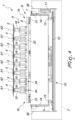
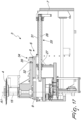
- the machine 1 comprises a supporting footing 2 which extends along the advancement direction A of the profile P being worked, a working assembly 3 associated with the footing 2 on each side of the advancement direction A and comprising at least one first roller 4 and at least one second roller 5, which are arranged at different work elevations and are supported in rotation about respective working axes A1 and A2 which are substantially vertical, and support, adjustment and rotational actuation means 6 of each one of the rollers 4 and 5.
- the at least one first roller 4 is arranged at a work elevation with respect to the footing 2 that is greater than the at least one second roller 5, being arranged above it, but it is not excluded that the opposite might occur.
- the working axes A1 and A2, respectively, of the at least one first roller 4 and of the at least one second roller 5 are offset parallel to the advancement direction A and the support, adjustment and rotational actuation means 6 are arranged below the rollers.
- offset means that they are spaced parallel to the advancement direction A and the individual working axes A1 and A2 can also be arranged at different distances from said advancement direction.
- the first and second rollers 4 and 5 each provide at least one rolling disk adapted to press, with its own peripheral region, against a corresponding external rib N'.
- first and second rollers 4 and/or 5 might provide two coaxial and rotationally integral disks in order to perform the simultaneous rolling of distinct external ribs N'.
- each working assembly 3 comprises a plurality of first rollers 4 and a plurality of second rollers 5 which are arranged so as to be mutually alternated and offset parallel to the advancement direction A.
- the first and second rollers 4 and 5 are distributed from the input region 1a to the exit region 1b of the profile P along the advancement direction.
- each working assembly 3 comprises four first rollers 4 and four second rollers 5 which are arranged so as to be mutually alternated and offset parallel to the advancement direction A.
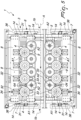
- first rollers 4 are integral, in rotation about the respective working axes A1, with corresponding first shafts 15 having a substantially vertical arrangement and the second rollers 5 are integral, in rotation about the respective working axes A2, with associated second shafts 16 having a substantially vertical arrangement.
- the support, adjustment and rotational actuation means 6 comprise first motor means 17 for actuating rotationally the first rollers 4 and a first gear system 18 for transmitting the rotation to the corresponding first shafts 15, which is associated at the lower ends of the first shafts 15.
- the support, adjustment and rotational actuation means 6 comprise second motor means 19 for rotational actuation of the second rollers 5 and a second gear system 20 for transmitting the rotation to the corresponding second shafts 16, which is associated at the lower ends of the second shafts 16.
- the support, adjustment and rotational actuation means 6 comprise a bed 7 which supports a first beam 8 for supporting the first rollers 4 and a second beam 9 for supporting the second rollers 5.
- the first and second beams 8 and 9 substantially extend parallel to the advancement direction A.
- the first and second beams 8 and 9 have a substantially horizontal arrangement.
- the bed 7 is associated with the footing 2 so as to slide in a substantially vertical direction, so as to be able to adjust the work elevation of the first and second rollers 4 and 5.
- the support, adjustment and rotational actuation means 6 comprise, furthermore, first actuation means 10 for the actuation with an alternating translational motion in a substantially vertical direction of the bed 7 with respect to the footing 2.
- Such first actuation means 10 can provide, for example, for a first motor 11 which, by virtue of a chain drive 12, actuates rotationally two first recirculating ballscrews 13 with a substantially vertical arrangement, which are supported by the footing 2 and are coupled to first nuts (not shown in the figures) associated with the bed 7 at the corresponding longitudinal ends along the advancement direction A in order to actuate the alternating translational motion thereof in a substantially vertical direction.
- the first actuation means 10 comprise first sliders 36 which are integral with the footing 2 and are coupled so as to slide along first guides 14 which have a substantially vertical arrangement and are associated with the bed 7 at the associated longitudinal ends along the advancement direction A.
- the first actuation means 10 of each working assembly 3 allow the simultaneous adjustment of the work elevation (height) of the corresponding first and second rollers 4 and 5.
- each working assembly 3 provides for first independent actuation means 10.
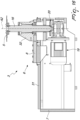
- each working assembly 3 the first rollers 4 are associated with the first beam 8 so as to slide in a substantially vertical direction. In this manner it is possible to adjust further the work elevation of the first rollers 4 with respect to that of the second rollers 5 of the same working assembly 3.
- the support, adjustment and rotational actuation means 6 comprise, therefore, second actuation means 21 for the actuation with an alternating translational motion in a substantially vertical direction of the first rollers 4 with respect to the first beam 8.
- first shafts 15 are associated so as to slide in a substantially vertical direction with respect to the first beam 8 and the second actuation means 21 ( Figures 9 and 15 ) can provide, for example, a support of said first shafts which can move in a substantially vertical direction along associated guides and is actuated so as to slide with an alternating motion by a dedicated servomotor.
- one of the working assemblies 3 has the second beam 9 associated integrally with the bed 7 in a horizontal and transverse direction with respect to the advancement direction A, so as to define a fixed reference for the arrangement of the profile P being worked.
- the first beam 8, instead, is associated so as to slide, with respect to the bed 7, in a substantially horizontal direction which is transverse with respect to the advancement direction A.
- this working assembly 3 with the second beam 9 integral with the bed 7 in a horizontal direction which is transverse to the advancement direction A is arranged on the left side of the machine 1 with respect to said advancement direction.
- the support, adjustment and rotational actuation means 6 comprise, therefore, third actuation means 22 for the actuation, with an alternating translational motion in a substantially horizontal direction which is transverse to the advancement direction A, of the first beam 8 with respect to the bed 7.
- Said third actuation means 22 can comprise, for example, at least one third recirculating ballscrew 23 which has a substantially horizontal arrangement, is supported by the bed 7 and is coupled to a third nut 24 which is integral with the first beam 8, and conventional third means for rotational actuation of said third screw, which are not visible in the figures.
- the other of the working assemblies 3 has both the first beam 8 and the second beam 9 associated with the bed 7 so that they can slide in a substantially horizontal direction which is transverse to the advancement direction A.
- the support, adjustment and rotational actuation means 6 comprise, therefore, fourth actuation means 25 for the actuation, with an alternating translational motion in a direction that is substantially horizontal and transverse to the advancement direction A, of the first and second beams 8 and 9 with respect to the bed 7.
- the fourth actuation means 25 can comprise, for example, at least one fourth recirculating ballscrew 26 which has a substantially horizontal arrangement, is supported by the bed 7 and is coupled to a fourth nut 27 which is integral with the first beam 8, and conventional fourth means for rotationally actuating said fourth screw, which are not visible in the figures, there being furthermore connection elements interposed between the first and second beams 8 and 9 for the translation actuation of said second beam.
- the first beam 8 is associated, so that it can slide in a substantially horizontal direction which is transverse to the advancement direction A, with the second beam 9.
- the support, adjustment and rotational actuation means 6 further comprise fifth actuation means 28, with an alternating translational motion in a substantially horizontal direction which is transverse to the advancement direction A, of the first beam 8 with respect to the second beam 9.
- Said fifth actuation means 28 can comprise, for example, at least one fifth recirculating ballscrew 29 which has a substantially horizontal arrangement, is supported by the second beam 9 and is coupled to a fifth nut 30 which is integral with the first beam 8, and conventional fifth means for rotationally actuating said fifth screw, which are not visible in the figures.
- the fifth actuation means 28 act as connection elements between the first and second beams 8 and 9 for simultaneous movement, with an alternating translational motion in a direction that is substantially horizontal and transverse to the advancement direction A, actuated by the fourth actuation means 25.
- the bed 7 provides, in an upper region, linear guides 31 to which the first beam 8 or both the first and second beams 8 and 9 are coupled so as to slide in a direction that is substantially horizontal and transverse to the advancement direction A.
- the sliding direction is preferably at right angles to the advancement direction A.
- the first beam is further spaced from the advancement direction A than the second beam 9, the first beam 8 being provided with a tab 32 for supporting each first roller 4 which can be inserted in a corresponding notch 33 formed in the second beam 9 between two adjacent second rollers 5 ( Figures 5 and 6 ).
- the first shafts 15 protrude in an upper region from respective supporting tabs 32.
- the working axes A1 of the first rollers 4 can be brought to the same distance from the advancement direction A as the working axes A2 of the second rollers 5 or even closer to said direction as a function of the depth of the notches 33 in order to optimize the flexibility of use of the machine 1 as the shape of the cross-section of the profile P varies.
- each one of the working assemblies 3 at least the last first roller 4 and the last second roller 5 along the advancement direction A are associated with means 34 for the fine adjustment of the position in a direction that is substantially horizontal and transverse to said advancement direction of the corresponding working axes A1 and A2.
- the fine adjustment means 34 can comprise, for example, a pusher screw 35 which presses against the supporting elements of the corresponding first or second shaft 15 or 16, which are supported with play by the corresponding beams 8 and 9.
- the machine 1 can be provided with a frame for the covering and protection of the working assemblies 3, provided with openings at the input region 1a and exit region 1b, which is not shown in the figures.
- the rolling machine according to the invention allows to optimize the arrangement of the rollers as a function of the type of profile being worked, allowing to perform its assembly easily and effectively regardless of the dimensions of the profile portions and of the connecting partitions that constitute it.
- the rolling machine according to the invention has the working region easily accessible for the mounting of any fixtures for supporting the profile being worked.
Landscapes
- Engineering & Computer Science (AREA)
- Mechanical Engineering (AREA)
- Civil Engineering (AREA)
- Structural Engineering (AREA)
- Machine Tool Units (AREA)
- Metal Rolling (AREA)
Claims (10)
- Eine Walzmaschine (1) zum Zusammenbauen von wärmegeschnittenen Profilen, die Folgendes umfasst: eine tragende Basis (2), die sich entlang einer Vorschubrichtung (A) eines bearbeiteten Profils (P) erstreckt, einen Arbeitsaufbau (3), der auf jeder Seite der Vorschubrichtung (A) mit der Basis (2) verbunden ist und mindestens eine erste Walze (4) und mindestens eine zweite Walze (5) umfasst, die auf verschiedenen Arbeitshöhen angeordnet und in der Drehung um entsprechende Arbeitsachsen (A1, A2) gelagert sind, die im Wesentlichen vertikal sind; und Lagerungs-, Einstell- und Drehantriebsmittel (6), die mit der mindestens einen ersten Walze (4) und mindestens einer zweiten Walze (5) verbunden sind; dadurch gekennzeichnet, dass bei jedem der Arbeitsaufbauten (3) die Arbeitsachsen (A1, A2) der mindestens einen ersten Walze (4) und mindestens einer zweiten Walze (5) parallel versetzt zu der Vorschubrichtung (A) angeordnet sind, und dadurch, dass die Lagerungs-, Einstell- und Drehantriebsmittel (6) unterhalb der mindestens einen ersten Walze (4) und der mindestens einen zweiten Walze (5) angeordnet sind.
- Die Maschine (1) gemäß Anspruch 1, dadurch gekennzeichnet, dass bei jedem der Arbeitsaufbauten (3) die Lagerungs-, Einstell- und Drehantriebsmittel (6) ein Bett (7) umfassen, das einen ersten Tragebalken (8) zum Tragen der mindestens einen ersten Walze (4) und einen zweiten Tragebalken (9) zum Tragen der mindestens einen zweiten Walze (5) trägt, der mit der Basis (2) verbunden ist, um in eine im Wesentlichen vertikale Richtung zu gleiten; wobei erste Antriebsmittel (10) zum Antreiben des Bettes (7) mit einer alternierenden Translationsbewegung in eine im Wesentlichen vertikale Richtung mit Bezug auf die Basis (2) bereitgestellt sind.
- Die Maschine (1) gemäß Anspruch 2, dadurch gekennzeichnet, dass die mindestens eine erste Walze (4) in eine im Wesentlichen vertikale Richtung gleitend mit dem ersten Tragebalken (8) verbunden ist, wobei die Lagerungs-, Einstell- und Drehantriebsmittel (6) weiter zweite Antriebsmittel (21) zum Antreiben der mindestens einen ersten Walze (4) mit einer alternierenden Translationsbewegung in einer im Wesentlichen vertikalen Richtung mit Bezug auf den ersten Tragebalken (8) umfasst.
- Die Maschine (1) gemäß Anspruch 2, dadurch gekennzeichnet, dass der erste Tragebalken (8) beim Gleiten in einer Richtung, die im Wesentlichen horizontal und quer zu der Vorschubrichtung (A) ist, mit dem Bett (7) verbunden ist; wobei die Lagerungs-, Einstell- und Drehantriebsmittel (6) weiter dritte Antriebsmittel (22) zum Antreiben des ersten Tragebalkens (8) mit einer alternierenden Translationsbewegung in einer Richtung umfassen, die im Wesentlichen horizontal und quer zur Vorschubrichtung (A) mit Bezug auf das Bett (7) ist; wobei der zweite Balken (9) integral mit dem Bett (7) verbunden ist.
- Die Maschine (1) gemäß Anspruch 2, dadurch gekennzeichnet, dass der erste und der zweite Tragebalken (8, 9) mit dem Bett (7) verbunden sind, um in eine Richtung zu gleiten, die im Wesentlichen horizontal und quer zu der Vorschubrichtung (A) ist; wobei die Lagerungs-, Einstell- und Drehantriebsmittel (6) weiter vierte Antriebsmittel (25) zum Antreiben des ersten und des zweiten Tragebalkens (8, 9) mit Bezug auf das Bett (7) mit einer alternierenden Translationsbewegung in einer Richtung umfassen, die im Wesentlichen horizontal und quer zur Vorschubrichtung (A) ist.
- Die Maschine (1) gemäß Anspruch 5, dadurch gekennzeichnet, dass der erste Tragebalken (8) mit dem zweiten Tragebalken (9) verbunden ist, um in einer im Wesentlichen horizontalen und transversalen Richtung mit Bezug auf die Vorschubrichtung (A) zu gleiten; wobei die Lagerungs-, Einstell- und Drehantriebsmittel (6) weiter fünfte Antriebsmittel (28) zum Antreiben des ersten Tragebalkens (8) mit Bezug auf den zweiten Tragebalken (9) in eine Richtung umfassen, die im Wesentlichen horizontal und quer zu der Vorschubrichtung (A) ist.
- Die Maschine (1) gemäß einem oder mehreren der obigen Ansprüche, dadurch gekennzeichnet, dass bei jedem Arbeitsaufbau (3) der erste Tragebalken (8) weiter von der Vorschubrichtung (A) beabstandet ist als der zweite Tragebalken (9); wobei der erste Tragebalken (8) mit mindestens einem Vorsprung (32) zum Tragen der mindestens einen Walze (4) ausgestattet ist, der in eine entsprechende im zweiten Tragebalken (9) geformte Nut (33) eingeführt werden kann.
- Die Maschine (1) gemäß einem oder mehreren der obigen Ansprüche, dadurch gekennzeichnet, dass bei jedem der Arbeitsaufbauten (3) die mindestens eine erste Walze (4) und die mindestens eine zweite Walze (5) mindestens eine dazugehörige Wälzscheibe umfassen.
- Die Maschine (1) gemäß einem oder mehreren der obigen Ansprüche, dadurch gekennzeichnet, dass jeder Arbeitsaufbau (3) eine Vielzahl der ersten Walzen (4) umfasst, die mit dem ersten Tragebalken (8) verbunden sind, und eine Vielzahl der zweiten Walzen (5), die mit dem zweiten Tragebalken (9) verbunden sind, wobei der erste und der zweite Balken (8, 9) sich parallel zur Vorschubrichtung (A) erstrecken.
- Die Maschine (1) gemäß Anspruch 9, dadurch gekennzeichnet, dass bei jedem der Arbeitsaufbauten (3) mindestens die letzte erste Walze (4) und die letzte zweite Walze (5) entlang der Vorschubrichtung (A) mit Mitteln (34) zur Feineinstellung der Position in einer Richtung verbunden sind, die im Wesentlichen horizontal und quer zu der Vorschubrichtung ist.
Applications Claiming Priority (1)
| Application Number | Priority Date | Filing Date | Title |
|---|---|---|---|
| IT102021000019100A IT202100019100A1 (it) | 2021-07-20 | 2021-07-20 | Macchina rullatrice per l'assemblaggio di profilati a taglio termico |
Publications (3)
| Publication Number | Publication Date |
|---|---|
| EP4122641A1 EP4122641A1 (de) | 2023-01-25 |
| EP4122641B1 true EP4122641B1 (de) | 2024-04-10 |
| EP4122641C0 EP4122641C0 (de) | 2024-04-10 |
Family
ID=78086776
Family Applications (1)
| Application Number | Title | Priority Date | Filing Date |
|---|---|---|---|
| EP22183366.8A Active EP4122641B1 (de) | 2021-07-20 | 2022-07-06 | Walzmaschine zum zusammenbauen von wärmegeschnittenen profilen |
Country Status (3)
| Country | Link |
|---|---|
| EP (1) | EP4122641B1 (de) |
| CA (1) | CA3167518A1 (de) |
| IT (1) | IT202100019100A1 (de) |
Family Cites Families (5)
| Publication number | Priority date | Publication date | Assignee | Title |
|---|---|---|---|---|
| DE2825301C2 (de) * | 1978-06-09 | 1983-01-13 | Wieland-Werke Ag, 7900 Ulm | Vorrichtung zur Herstellung eines wärmegedämmten Verbundprofils |
| DE3302274A1 (de) * | 1983-01-25 | 1984-07-26 | Manfred 4972 Löhne Mühle | Vorrichtung zum herstellen waermegedaemmter verbundprofile fuer fenster, tueren und fassaden |
| DE3313315A1 (de) * | 1983-04-13 | 1984-10-18 | Helmut 3167 Burgdorf Haberer | Maschine zum schubfesten verbinden von halbprofilschalen mittels kunststoffleisten |
| EP1949982B1 (de) * | 2008-05-14 | 2012-07-25 | Müller Technologies AG | Walzvorrichtung und Verfahren zum Einrollen von Verbindungsstegen in Profile |
| BE1023565B1 (nl) * | 2015-11-20 | 2017-05-05 | Aluro Nv | Machine evenals werkwijze voor het assembleren van profielen |
-
2021
- 2021-07-20 IT IT102021000019100A patent/IT202100019100A1/it unknown
-
2022
- 2022-07-06 EP EP22183366.8A patent/EP4122641B1/de active Active
- 2022-07-12 CA CA3167518A patent/CA3167518A1/en active Pending
Also Published As
| Publication number | Publication date |
|---|---|
| CA3167518A1 (en) | 2023-01-20 |
| EP4122641A1 (de) | 2023-01-25 |
| IT202100019100A1 (it) | 2023-01-20 |
| EP4122641C0 (de) | 2024-04-10 |
Similar Documents
| Publication | Publication Date | Title |
|---|---|---|
| JP5180799B2 (ja) | アクチュエータ | |
| KR101280762B1 (ko) | 구름 안내 장치 및 그 제조 방법 | |
| US5553947A (en) | Guide rail for railborne load carriers | |
| US20110179842A1 (en) | System for cold roll forming profiles having variable cross-sections | |
| EP4122641B1 (de) | Walzmaschine zum zusammenbauen von wärmegeschnittenen profilen | |
| CN115318888B (zh) | 金属型材成型压瓦机 | |
| CN116571596A (zh) | 一种钢结构平直矫正机械加工设备及加工方法 | |
| KR100555692B1 (ko) | 슬라이드 장치 | |
| CN116900096A (zh) | 一种宽扁金属型材调直装置及方法 | |
| US6648568B2 (en) | Linear blind broaching machine | |
| CN221537760U (zh) | 一种旁弯夹持机构及旁弯整改装置 | |
| CN108367331B (zh) | 用于异型件的组装的机器和方法 | |
| KR102872163B1 (ko) | 프레스기 | |
| KR20010108312A (ko) | 2차원으로 롤 처짐을 조정하는 압연기 | |
| CN118455292A (zh) | 一种铝型材散热器、挤压设备以及加工步骤 | |
| KR20100086887A (ko) | 롤러 헤밍장치의 롤러헤밍유닛 | |
| CN212494725U (zh) | 一种铝挤出在线滚弯治具 | |
| EP0213880A2 (de) | Formung einer Sprengringnut | |
| JPH11192511A (ja) | 断熱形材の組付け装置 | |
| EP4417828B1 (de) | Linearführungsvorrichtung | |
| CN219712226U (zh) | 滚珠丝杆式直线滑台 | |
| EP0712674A1 (de) | Profilwalzeneinrichtung | |
| CN223748346U (zh) | 一种可调式打孔装置 | |
| EP4378602B1 (de) | Verfahren und vorrichtung zur herstellung einer aufzugsführungsschiene und entsprechende aufzugsführungsschiene | |
| CN114472744B (zh) | 散热底座与热导管的铆合方法 |
Legal Events
| Date | Code | Title | Description |
|---|---|---|---|
| PUAI | Public reference made under article 153(3) epc to a published international application that has entered the european phase |
Free format text: ORIGINAL CODE: 0009012 |
|
| STAA | Information on the status of an ep patent application or granted ep patent |
Free format text: STATUS: THE APPLICATION HAS BEEN PUBLISHED |
|
| AK | Designated contracting states |
Kind code of ref document: A1 Designated state(s): AL AT BE BG CH CY CZ DE DK EE ES FI FR GB GR HR HU IE IS IT LI LT LU LV MC MK MT NL NO PL PT RO RS SE SI SK SM TR |
|
| STAA | Information on the status of an ep patent application or granted ep patent |
Free format text: STATUS: REQUEST FOR EXAMINATION WAS MADE |
|
| 17P | Request for examination filed |
Effective date: 20230525 |
|
| RBV | Designated contracting states (corrected) |
Designated state(s): AL AT BE BG CH CY CZ DE DK EE ES FI FR GB GR HR HU IE IS IT LI LT LU LV MC MK MT NL NO PL PT RO RS SE SI SK SM TR |
|
| RIC1 | Information provided on ipc code assigned before grant |
Ipc: E06B 3/263 20060101ALI20230927BHEP Ipc: B21D 39/04 20060101ALI20230927BHEP Ipc: B21D 47/04 20060101ALI20230927BHEP Ipc: B21D 53/74 20060101ALI20230927BHEP Ipc: E06B 3/273 20060101ALI20230927BHEP Ipc: B23P 11/00 20060101AFI20230927BHEP |
|
| GRAP | Despatch of communication of intention to grant a patent |
Free format text: ORIGINAL CODE: EPIDOSNIGR1 |
|
| STAA | Information on the status of an ep patent application or granted ep patent |
Free format text: STATUS: GRANT OF PATENT IS INTENDED |
|
| INTG | Intention to grant announced |
Effective date: 20231109 |
|
| GRAS | Grant fee paid |
Free format text: ORIGINAL CODE: EPIDOSNIGR3 |
|
| GRAA | (expected) grant |
Free format text: ORIGINAL CODE: 0009210 |
|
| STAA | Information on the status of an ep patent application or granted ep patent |
Free format text: STATUS: THE PATENT HAS BEEN GRANTED |
|
| AK | Designated contracting states |
Kind code of ref document: B1 Designated state(s): AL AT BE BG CH CY CZ DE DK EE ES FI FR GB GR HR HU IE IS IT LI LT LU LV MC MK MT NL NO PL PT RO RS SE SI SK SM TR |
|
| REG | Reference to a national code |
Ref country code: GB Ref legal event code: FG4D |
|
| REG | Reference to a national code |
Ref country code: CH Ref legal event code: EP |
|
| REG | Reference to a national code |
Ref country code: DE Ref legal event code: R096 Ref document number: 602022002795 Country of ref document: DE |
|
| REG | Reference to a national code |
Ref country code: IE Ref legal event code: FG4D |
|
| U01 | Request for unitary effect filed |
Effective date: 20240508 |
|
| U07 | Unitary effect registered |
Designated state(s): AT BE BG DE DK EE FI FR IT LT LU LV MT NL PT SE SI Effective date: 20240516 |
|
| U20 | Renewal fee for the european patent with unitary effect paid |
Year of fee payment: 3 Effective date: 20240722 |
|
| PG25 | Lapsed in a contracting state [announced via postgrant information from national office to epo] |
Ref country code: IS Free format text: LAPSE BECAUSE OF FAILURE TO SUBMIT A TRANSLATION OF THE DESCRIPTION OR TO PAY THE FEE WITHIN THE PRESCRIBED TIME-LIMIT Effective date: 20240810 |
|
| PG25 | Lapsed in a contracting state [announced via postgrant information from national office to epo] |
Ref country code: HR Free format text: LAPSE BECAUSE OF FAILURE TO SUBMIT A TRANSLATION OF THE DESCRIPTION OR TO PAY THE FEE WITHIN THE PRESCRIBED TIME-LIMIT Effective date: 20240410 |
|
| PG25 | Lapsed in a contracting state [announced via postgrant information from national office to epo] |
Ref country code: GR Free format text: LAPSE BECAUSE OF FAILURE TO SUBMIT A TRANSLATION OF THE DESCRIPTION OR TO PAY THE FEE WITHIN THE PRESCRIBED TIME-LIMIT Effective date: 20240711 |
|
| PG25 | Lapsed in a contracting state [announced via postgrant information from national office to epo] |
Ref country code: ES Free format text: LAPSE BECAUSE OF FAILURE TO SUBMIT A TRANSLATION OF THE DESCRIPTION OR TO PAY THE FEE WITHIN THE PRESCRIBED TIME-LIMIT Effective date: 20240410 |
|
| PG25 | Lapsed in a contracting state [announced via postgrant information from national office to epo] |
Ref country code: PL Free format text: LAPSE BECAUSE OF FAILURE TO SUBMIT A TRANSLATION OF THE DESCRIPTION OR TO PAY THE FEE WITHIN THE PRESCRIBED TIME-LIMIT Effective date: 20240410 |
|
| PG25 | Lapsed in a contracting state [announced via postgrant information from national office to epo] |
Ref country code: PL Free format text: LAPSE BECAUSE OF FAILURE TO SUBMIT A TRANSLATION OF THE DESCRIPTION OR TO PAY THE FEE WITHIN THE PRESCRIBED TIME-LIMIT Effective date: 20240410 Ref country code: NO Free format text: LAPSE BECAUSE OF FAILURE TO SUBMIT A TRANSLATION OF THE DESCRIPTION OR TO PAY THE FEE WITHIN THE PRESCRIBED TIME-LIMIT Effective date: 20240710 Ref country code: IS Free format text: LAPSE BECAUSE OF FAILURE TO SUBMIT A TRANSLATION OF THE DESCRIPTION OR TO PAY THE FEE WITHIN THE PRESCRIBED TIME-LIMIT Effective date: 20240810 Ref country code: HR Free format text: LAPSE BECAUSE OF FAILURE TO SUBMIT A TRANSLATION OF THE DESCRIPTION OR TO PAY THE FEE WITHIN THE PRESCRIBED TIME-LIMIT Effective date: 20240410 Ref country code: GR Free format text: LAPSE BECAUSE OF FAILURE TO SUBMIT A TRANSLATION OF THE DESCRIPTION OR TO PAY THE FEE WITHIN THE PRESCRIBED TIME-LIMIT Effective date: 20240711 Ref country code: ES Free format text: LAPSE BECAUSE OF FAILURE TO SUBMIT A TRANSLATION OF THE DESCRIPTION OR TO PAY THE FEE WITHIN THE PRESCRIBED TIME-LIMIT Effective date: 20240410 Ref country code: RS Free format text: LAPSE BECAUSE OF FAILURE TO SUBMIT A TRANSLATION OF THE DESCRIPTION OR TO PAY THE FEE WITHIN THE PRESCRIBED TIME-LIMIT Effective date: 20240710 |
|
| REG | Reference to a national code |
Ref country code: DE Ref legal event code: R097 Ref document number: 602022002795 Country of ref document: DE |
|
| PG25 | Lapsed in a contracting state [announced via postgrant information from national office to epo] |
Ref country code: CZ Free format text: LAPSE BECAUSE OF FAILURE TO SUBMIT A TRANSLATION OF THE DESCRIPTION OR TO PAY THE FEE WITHIN THE PRESCRIBED TIME-LIMIT Effective date: 20240410 |
|
| PG25 | Lapsed in a contracting state [announced via postgrant information from national office to epo] |
Ref country code: SK Free format text: LAPSE BECAUSE OF FAILURE TO SUBMIT A TRANSLATION OF THE DESCRIPTION OR TO PAY THE FEE WITHIN THE PRESCRIBED TIME-LIMIT Effective date: 20240410 Ref country code: RO Free format text: LAPSE BECAUSE OF FAILURE TO SUBMIT A TRANSLATION OF THE DESCRIPTION OR TO PAY THE FEE WITHIN THE PRESCRIBED TIME-LIMIT Effective date: 20240410 |
|
| PG25 | Lapsed in a contracting state [announced via postgrant information from national office to epo] |
Ref country code: SM Free format text: LAPSE BECAUSE OF FAILURE TO SUBMIT A TRANSLATION OF THE DESCRIPTION OR TO PAY THE FEE WITHIN THE PRESCRIBED TIME-LIMIT Effective date: 20240410 |
|
| PG25 | Lapsed in a contracting state [announced via postgrant information from national office to epo] |
Ref country code: SM Free format text: LAPSE BECAUSE OF FAILURE TO SUBMIT A TRANSLATION OF THE DESCRIPTION OR TO PAY THE FEE WITHIN THE PRESCRIBED TIME-LIMIT Effective date: 20240410 Ref country code: SK Free format text: LAPSE BECAUSE OF FAILURE TO SUBMIT A TRANSLATION OF THE DESCRIPTION OR TO PAY THE FEE WITHIN THE PRESCRIBED TIME-LIMIT Effective date: 20240410 Ref country code: RO Free format text: LAPSE BECAUSE OF FAILURE TO SUBMIT A TRANSLATION OF THE DESCRIPTION OR TO PAY THE FEE WITHIN THE PRESCRIBED TIME-LIMIT Effective date: 20240410 Ref country code: CZ Free format text: LAPSE BECAUSE OF FAILURE TO SUBMIT A TRANSLATION OF THE DESCRIPTION OR TO PAY THE FEE WITHIN THE PRESCRIBED TIME-LIMIT Effective date: 20240410 |
|
| PG25 | Lapsed in a contracting state [announced via postgrant information from national office to epo] |
Ref country code: MC Free format text: LAPSE BECAUSE OF FAILURE TO SUBMIT A TRANSLATION OF THE DESCRIPTION OR TO PAY THE FEE WITHIN THE PRESCRIBED TIME-LIMIT Effective date: 20240410 |
|
| PLBE | No opposition filed within time limit |
Free format text: ORIGINAL CODE: 0009261 |
|
| STAA | Information on the status of an ep patent application or granted ep patent |
Free format text: STATUS: NO OPPOSITION FILED WITHIN TIME LIMIT |
|
| 26N | No opposition filed |
Effective date: 20250113 |
|
| PG25 | Lapsed in a contracting state [announced via postgrant information from national office to epo] |
Ref country code: IE Free format text: LAPSE BECAUSE OF NON-PAYMENT OF DUE FEES Effective date: 20240706 |
|
| U20 | Renewal fee for the european patent with unitary effect paid |
Year of fee payment: 4 Effective date: 20250721 |
|
| PGFP | Annual fee paid to national office [announced via postgrant information from national office to epo] |
Ref country code: CH Payment date: 20250801 Year of fee payment: 4 |
|
| PG25 | Lapsed in a contracting state [announced via postgrant information from national office to epo] |
Ref country code: CY Free format text: LAPSE BECAUSE OF FAILURE TO SUBMIT A TRANSLATION OF THE DESCRIPTION OR TO PAY THE FEE WITHIN THE PRESCRIBED TIME-LIMIT; INVALID AB INITIO Effective date: 20220706 |
|
| PG25 | Lapsed in a contracting state [announced via postgrant information from national office to epo] |
Ref country code: HU Free format text: LAPSE BECAUSE OF FAILURE TO SUBMIT A TRANSLATION OF THE DESCRIPTION OR TO PAY THE FEE WITHIN THE PRESCRIBED TIME-LIMIT; INVALID AB INITIO Effective date: 20220706 |