EP4121296B1 - Ditherverfahren für hochgeschwindigkeits-einzelpassdruck - Google Patents
Ditherverfahren für hochgeschwindigkeits-einzelpassdruck Download PDFInfo
- Publication number
- EP4121296B1 EP4121296B1 EP21711826.4A EP21711826A EP4121296B1 EP 4121296 B1 EP4121296 B1 EP 4121296B1 EP 21711826 A EP21711826 A EP 21711826A EP 4121296 B1 EP4121296 B1 EP 4121296B1
- Authority
- EP
- European Patent Office
- Prior art keywords
- resolution
- image
- printing
- halftone
- printhead
- Prior art date
- Legal status (The legal status is an assumption and is not a legal conclusion. Google has not performed a legal analysis and makes no representation as to the accuracy of the status listed.)
- Active
Links
Images


Classifications
-
- H—ELECTRICITY
- H04—ELECTRIC COMMUNICATION TECHNIQUE
- H04N—PICTORIAL COMMUNICATION, e.g. TELEVISION
- H04N1/00—Scanning, transmission or reproduction of documents or the like, e.g. facsimile transmission; Details thereof
- H04N1/40—Picture signal circuits
- H04N1/405—Halftoning, i.e. converting the picture signal of a continuous-tone original into a corresponding signal showing only two levels
-
- B—PERFORMING OPERATIONS; TRANSPORTING
- B41—PRINTING; LINING MACHINES; TYPEWRITERS; STAMPS
- B41J—TYPEWRITERS; SELECTIVE PRINTING MECHANISMS, i.e. MECHANISMS PRINTING OTHERWISE THAN FROM A FORME; CORRECTION OF TYPOGRAPHICAL ERRORS
- B41J2/00—Typewriters or selective printing mechanisms characterised by the printing or marking process for which they are designed
- B41J2/005—Typewriters or selective printing mechanisms characterised by the printing or marking process for which they are designed characterised by bringing liquid or particles selectively into contact with a printing material
- B41J2/01—Ink jet
- B41J2/21—Ink jet for multi-colour printing
- B41J2/2132—Print quality control characterised by dot disposition, e.g. for reducing white stripes or banding
- B41J2/2146—Print quality control characterised by dot disposition, e.g. for reducing white stripes or banding for line print heads
-
- B—PERFORMING OPERATIONS; TRANSPORTING
- B41—PRINTING; LINING MACHINES; TYPEWRITERS; STAMPS
- B41J—TYPEWRITERS; SELECTIVE PRINTING MECHANISMS, i.e. MECHANISMS PRINTING OTHERWISE THAN FROM A FORME; CORRECTION OF TYPOGRAPHICAL ERRORS
- B41J2/00—Typewriters or selective printing mechanisms characterised by the printing or marking process for which they are designed
- B41J2/005—Typewriters or selective printing mechanisms characterised by the printing or marking process for which they are designed characterised by bringing liquid or particles selectively into contact with a printing material
- B41J2/01—Ink jet
- B41J2/21—Ink jet for multi-colour printing
- B41J2/2132—Print quality control characterised by dot disposition, e.g. for reducing white stripes or banding
-
- B—PERFORMING OPERATIONS; TRANSPORTING
- B41—PRINTING; LINING MACHINES; TYPEWRITERS; STAMPS
- B41J—TYPEWRITERS; SELECTIVE PRINTING MECHANISMS, i.e. MECHANISMS PRINTING OTHERWISE THAN FROM A FORME; CORRECTION OF TYPOGRAPHICAL ERRORS
- B41J2/00—Typewriters or selective printing mechanisms characterised by the printing or marking process for which they are designed
- B41J2/485—Typewriters or selective printing mechanisms characterised by the printing or marking process for which they are designed characterised by the process of building-up characters or image elements applicable to two or more kinds of printing or marking processes
- B41J2/505—Typewriters or selective printing mechanisms characterised by the printing or marking process for which they are designed characterised by the process of building-up characters or image elements applicable to two or more kinds of printing or marking processes from an assembly of identical printing elements
- B41J2/515—Typewriters or selective printing mechanisms characterised by the printing or marking process for which they are designed characterised by the process of building-up characters or image elements applicable to two or more kinds of printing or marking processes from an assembly of identical printing elements line printer type
-
- G—PHYSICS
- G06—COMPUTING OR CALCULATING; COUNTING
- G06K—GRAPHICAL DATA READING; PRESENTATION OF DATA; RECORD CARRIERS; HANDLING RECORD CARRIERS
- G06K15/00—Arrangements for producing a permanent visual presentation of the output data, e.g. computer output printers
- G06K15/02—Arrangements for producing a permanent visual presentation of the output data, e.g. computer output printers using printers
- G06K15/027—Test patterns and calibration
-
- G—PHYSICS
- G06—COMPUTING OR CALCULATING; COUNTING
- G06K—GRAPHICAL DATA READING; PRESENTATION OF DATA; RECORD CARRIERS; HANDLING RECORD CARRIERS
- G06K15/00—Arrangements for producing a permanent visual presentation of the output data, e.g. computer output printers
- G06K15/02—Arrangements for producing a permanent visual presentation of the output data, e.g. computer output printers using printers
- G06K15/10—Arrangements for producing a permanent visual presentation of the output data, e.g. computer output printers using printers by matrix printers
- G06K15/102—Arrangements for producing a permanent visual presentation of the output data, e.g. computer output printers using printers by matrix printers using ink jet print heads
- G06K15/105—Multipass or interlaced printing
-
- G—PHYSICS
- G06—COMPUTING OR CALCULATING; COUNTING
- G06K—GRAPHICAL DATA READING; PRESENTATION OF DATA; RECORD CARRIERS; HANDLING RECORD CARRIERS
- G06K15/00—Arrangements for producing a permanent visual presentation of the output data, e.g. computer output printers
- G06K15/02—Arrangements for producing a permanent visual presentation of the output data, e.g. computer output printers using printers
- G06K15/18—Conditioning data for presenting it to the physical printing elements
- G06K15/1867—Post-processing of the composed and rasterized print image
- G06K15/1872—Image enhancement
- G06K15/1876—Decreasing spatial resolution; Dithering
- G06K15/1877—Decreasing spatial resolution; Dithering with provisions for treating some of the print data differently
-
- G—PHYSICS
- G06—COMPUTING OR CALCULATING; COUNTING
- G06K—GRAPHICAL DATA READING; PRESENTATION OF DATA; RECORD CARRIERS; HANDLING RECORD CARRIERS
- G06K15/00—Arrangements for producing a permanent visual presentation of the output data, e.g. computer output printers
- G06K15/02—Arrangements for producing a permanent visual presentation of the output data, e.g. computer output printers using printers
- G06K15/18—Conditioning data for presenting it to the physical printing elements
- G06K15/1867—Post-processing of the composed and rasterized print image
- G06K15/1872—Image enhancement
- G06K15/1881—Halftoning
-
- H—ELECTRICITY
- H04—ELECTRIC COMMUNICATION TECHNIQUE
- H04N—PICTORIAL COMMUNICATION, e.g. TELEVISION
- H04N1/00—Scanning, transmission or reproduction of documents or the like, e.g. facsimile transmission; Details thereof
- H04N1/46—Colour picture communication systems
- H04N1/52—Circuits or arrangements for halftone screening
-
- B—PERFORMING OPERATIONS; TRANSPORTING
- B41—PRINTING; LINING MACHINES; TYPEWRITERS; STAMPS
- B41J—TYPEWRITERS; SELECTIVE PRINTING MECHANISMS, i.e. MECHANISMS PRINTING OTHERWISE THAN FROM A FORME; CORRECTION OF TYPOGRAPHICAL ERRORS
- B41J2202/00—Embodiments of or processes related to ink-jet or thermal heads
- B41J2202/01—Embodiments of or processes related to ink-jet heads
- B41J2202/21—Line printing
-
- B—PERFORMING OPERATIONS; TRANSPORTING
- B41—PRINTING; LINING MACHINES; TYPEWRITERS; STAMPS
- B41M—PRINTING, DUPLICATING, MARKING, OR COPYING PROCESSES; COLOUR PRINTING
- B41M5/00—Duplicating or marking methods; Sheet materials for use therein
- B41M5/50—Recording sheets characterised by the coating used to improve ink, dye or pigment receptivity, e.g. for ink-jet or thermal dye transfer recording
Definitions
- the present invention relates to a method of dithering for high-speed single-pass printing. It has been developed primarily for optimizing print quality when printing using multiple monochrome printheads aligned along a media feed direction.
- Single-pass (“pagewide”) printing dramatically increases print speeds compared to traditional scanning printheads.
- One application of single-pass printing is in digital inkjet presses, as described in, for example, US 10,457,075 ; US 10,081,204 and US 9,421,790 .
- CMYK complementary metal-oxide-semiconductor
- print speeds may be increased by increasing the number of printheads used to print each color.
- a monochrome black printing system may double its printing speed by doubling the number of printheads printing black ink - a first printhead may print half of the dots required by a halftone image and a second downstream printhead may print the other half of the dots. It will be appreciated that print speeds may be tripled, quadrupled etc. by further increasing the number of aligned printheads.
- halftone images (or bitmaps) containing discrete dots at a specified printing resolution are generated from contone images using a dithering process.
- the halftone image needs to be divided (“deinterleaved") into two portions, one for each printhead.
- alternate lines of the halftone image may be printed by each of the two printheads - the first printhead printing odd lines of the image and the downstream second printhead printing even lines of the image or vice versa.
- each printhead receives a halftone image at half the resolution (in the printing direction) of the full halftone image.
- each printhead would receive a respective halftone image at a resolution of 1600 x 395 dpi.
- the two halftone images are interleaved by the two printheads during printing to recreate the full halftone image at the target resolution of 1600 x 790 dpi.
- Printing at increased speeds using multiple high-resolution printheads in the manner described above requires excellent alignment of the printheads. Without excellent alignment of the printheads, print quality generally declines to an extent that is unacceptable to users.
- Misalignment of printheads may arise from a number of sources. Firstly, mechanical placement of the printheads must be accurately controlled to within a few microns in order to avoid misalignment between a pair of printheads.
- the Applicant has previously described sophisticated alignment patterns (see US 11,312,126 ), which may be used to determine misalignments and allow fine correction thereof using suitable mechanical means.
- alignment patterns see US 11,312,126
- relative misalignments are still possible due to the small differences in the conformation of individual printheads, arising from their manufacturing process. For example, in relatively long pagewide printheads, the printheads have a tendency to bow along their long axis, some more than others depending on the precise manufacturing conditions.
- printheads Users expect printheads to be replaceable with any printhead of the same type; moreover, measuring an extent of bowing and then categorizing printheads based on such measurements adds complexity and expense to the supply chain. Even with such a categorization of printheads at the factory, the extent of bowing may change due to other factors in the field. For example, a printhead nest which mechanically holds the printhead when installed in a printing system may affect the extent of bowing. Hence, characterization of printhead bowing at the factory may not be a good indicator of printhead bowing in the field.
- US 2009/0244580 describes a method of single-pass printing using two wholly aligned printheads supplied with a same colored ink.
- the method analyses grayscale values (density values) of pixels and allocates printing of each pixel to either one or both printheads depending on whether the grayscale value exceeds a certain threshold.
- the term "ink” is taken to mean any printing fluid, which may be printed from an inkjet printhead.
- the ink may or may not contain a colorant.
- the term “ink” may include conventional dye-based or pigment-based inks, infrared inks, fixatives (e.g. pre-coats and finishers), 3D printing fluids and the like. Where reference is made to fluids or printing fluids, this is not intended to limit the meaning of "ink” herein.
- the term "aligned printheads” is taken to mean a plurality of printheads that are generally aligned along a media feed direction, such that any one of the printheads is capable of printing onto a same part of the media as any other printhead.
- the term “aligned printheads” should not necessarily be taken to mean perfect alignment, positioning and/or matching of printheads as foreshadowed above.
- the present invention addresses the problem of small misalignments (e.g. less than 500 micron, less than 200 micron, less than 100 micron or less than 50 micron misalignments) between generally aligned printheads.
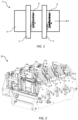
- a printing system 1 comprising a first printhead 2 and a second printhead 4 positioned downstream of the first printhead relative to a media feed direction indicated by arrow F.
- the second printhead is aligned with the first printhead in the media feed direction insofar as both printheads are capable of printing onto a same portion of media 6 (e.g. cut-sheet media or a roll-to-roll fed media web).
- An extent of alignment between the first and second printheads 2 and 4 may vary according to individual printhead conformations, printhead placement accuracy etc, as described above.
- Each of the first and second printheads 2 and 4 is a monochrome printhead supplied with a same ink so as to enable double-speed printing.
- each printhead prints half an image at half the target resolution (in the media direction F).
- a full halftone image may be generated at a target resolution of 1600 x 790 dpi and each of the first and second printheads 2 and 4 is configured to print at a resolution of 1600 x 395 dpi.
- each printhead prints respective alternate lines (row) of the full halftone image. Since printheads have a maximum drop ejection frequency, it will be appreciated that halving the resolution in the media feed direction F enables printing at twice the speed that would otherwise be obtainable.
- Each of the first and second printheads 2 and 4 is typically a component of a print module, which may additionally comprise a printhead mounting structure, electronics for supply of data and power to the printhead, ink couplings, pressure regulator(s) etc. Examples of suitable print modules are described in US 10,457,075 and US 10,081,204 .
- a print engine 10 having four aligned print modules 12 as described in US 2019/0118537 .
- Each print module 12 comprises a respective printhead (not visible in Figure 2 ) as well as ink couplings, PCBs etc.
- the print engine 10 having four aligned printheads supplied with a same ink potentially enables quadruple-speed printing by allocating a quarter of a full halftone image to each of the four print modules 12. For example, every 4 th line of the full halftone image may be allocated to a respective print module 12, such that each printhead prints at one 1 ⁇ 4 resolution in the media feed direction.
- a full halftone image generated at a resolution of 1600 x 800 dpi would be printed at a resolution of 1600 x 200 dpi by each printhead, thereby enabling the print engine 10 to print at quadruple speed compared to a single print module 12.
- any number of n printheads may be used to print at n times speed by allocated 1/n of a full halftone image (e.g. every nth line of the halftone image) to a respective one of the n printheads.
- the aligned printheads may be part of a matrix of printheads arranged for color and/or wideformat printing.
- Figure 3 shows schematically a print engine 20 containing sixteen print modules 12 in an 8 ⁇ 2 array for full color printing.
- the print modules 12 are arranged in sets of four for printing each of four colors (KCMY).
- KCMY color channels
- the pair of print modules 12A are aligned and the pair of print modules 12B are aligned along the media feed direction F.
- each ink (color) channel is capable of printing at double speed in the manner described above in connection with Figure 1 .
- FIG. 4 there is shown a simple method, not according to the invention, of processing a contone image at a first resolution for high-speed printing using the first printhead 2 and the second printhead 4 shown in Figure 1 .
- the method is performed in a raster image processor (RIP) although, for the sake of clarity, not all processing steps performed by the RIP are shown in Figure 4 .
- the contone image is a contone (grayscale) bitmap for a single ink channel at the target printing resolution of 1600 x 790 dpi.
- typical upstream processing steps in the RIP e.g. rasterizing, color space conversion, ink channel separation, calibration to the target printing resolution etc ) are not shown in Figure 4 .
- the contone image is dithered using a conventional single dither pattern (e.g. a blue noise dither as described in US 5,111,310 or a green noise dither as described in US 6,493,112 etc .) to generate a full halftone image.
- the full halftone image is then divided into a first halftone image and a second halftone image, each at a second resolution, in a process known as "deinterleaving". Alternate rows of the full halftone image are allocated to respective printheads, such that each of the first and second halftone images resulting from the deinterleaving process has a resolution of 1600 x 395 dpi.
- the first halftone image may comprise odd lines (1, 3, 5, 7 etc .) of the full halftone image and the second halftone image may comprises even lines (0, 2, 4, 8 etc .) of the full halftone image or vice versa.
- the first and second halftone images are then sent to respective first and second printheads of a print engine and for printing.
- the full printed image 8 contains the first and second halftone images interleaved on the media 6 to represent the full halftone image generated from the dithering process.
- the half-density image 9 printed by the upstream first printhead 2 is based on the first halftone image only and is therefore printed at half density (alternate lines of the full halftone image).
- the contone image is deinterleaved prior to dithering.
- Deinterleaving of the contone image is performed similarly to the deinterleaving process described above, whereby alternate lines of the full contone image are allocated to a first contone image and a second contone image.
- the first contone image is then dithered using a first dither pattern to generate the first halftone image and the second contone image is dithered using a second dither pattern to generate the second halftone image.
- the first and second dither patterns are different.
- the printed image 8 When the first and second halftone images are printed using respective printheads, the printed image 8 generally has acceptable print quality.
- print quality is relatively tolerant of misalignments between the first printhead printhead 2 and the second printhead 4 compared to the method described above in connection with Figure 4 .
- the method according to the first embodiment produces lower print quality than the method described above.
- the dithering step in the method shown in Figure 6 employs a combined dither pattern comprising the first dither pattern and the second dither pattern.
- alternate lines of the combined dither pattern are based on different dither patterns.
- odd lines of the combined dither pattern may be based on the first dither pattern and even lines of the combined dither pattern may be based on the second dither pattern, which is different than the first dither pattern.
- first and second halftone images which are identical to the first and second halftone images described above in connection with Figure 5 .
- the method according to the second embodiment therefore, enjoys the same advantages as the method according to the first embodiment.
- an additional advantage of the method according to the second embodiment is that the datapath uses the same sequence of processing steps as those shown in Figure 4 . Therefore, by simply substituting a conventional single dither pattern applied to the full contone image with the combined dither pattern, the RIP can readily switch between these two methods in order to optimize print quality for a given scenario.
- a user may provide empirical qualitative feedback on print quality and the dither may be switched accordingly.
- a printhead alignment test pattern may provide quantitative printhead alignment data, which can be used to select the most appropriate dither pattern.
- the dither pattern may be selected automatically based on a printhead alignment measurement relative to a predetermined threshold. For example, if the printheads are determined to be aligned to within one dot pitch or less (in the printing direction) at the resolution of the first and second halftone images (i.e. within 64 microns for a 1600 x 395 dpi halftone image), then a single dither pattern may be employed, as shown in Figure 4 . However, if the printheads are aligned only to greater than one dot pitch (in the printing direction) at the resolution of the first and second halftone images ( i.e.
- the combined dither pattern may be employed, as shown in Figure 6 .
- the predetermined threshold may be variable depending on printing parameters (e.g. print speed, print media type, ink type etc .). In this way, print quality can be optimized for both well-aligned and somewhat misaligned printheads.
Landscapes
- Engineering & Computer Science (AREA)
- Physics & Mathematics (AREA)
- General Engineering & Computer Science (AREA)
- General Physics & Mathematics (AREA)
- Theoretical Computer Science (AREA)
- Quality & Reliability (AREA)
- Multimedia (AREA)
- Signal Processing (AREA)
- Mathematical Physics (AREA)
- Ink Jet (AREA)
- Particle Formation And Scattering Control In Inkjet Printers (AREA)
- Color, Gradation (AREA)
Claims (14)
- Verfahren zum Einzelpassdrucken unter Verwendung eines Drucksystems, das mindestens einen ersten und einen zweiten vollständig ausgerichteten monochromen Druckkopf umfasst, die mit derselben Tinte versorgt werden, wobei sich der zweite Druckkopf stromabwärts des ersten Druckkopfs befindet, wobei das Verfahren die folgenden Schritte umfasst:Empfangen eines ersten und eines zweiten Halbtonbildes an dem ersten bzw. dem zweiten Druckkopf;Drucken des ersten Halbtonbildes mit dem ersten Druckkopf; undDrucken des zweiten Halbtonbildes mit dem zweiten Druckkopf, sodass das resultierende gedruckte Bild das zweite Halbtonbild verschachtelt mit dem ersten Halbtonbild enthält,wobei:das gedruckte Bild mit einer ersten Auflösung in einer Druckrichtung gedruckt wird;das erste und das zweite Halbtonbild eine zweite Auflösung in der Druckrichtung aufweisen;das erste Halbtonbild auf einem ersten Dithermuster basiert und das zweite Halbtonbild auf einem zweiten Dithermuster basiert, wobei sich das erste Dithermuster von dem zweiten Dithermuster unterscheidet,und dadurch gekennzeichnet, dass:
die zweite Auflösung kleiner als die erste Auflösung ist. - Verfahren nach Anspruch 1, ferner umfassend die Schritte des Bereitstellens eines Volltonbildes für einen Tintenkanal des Drucksystems mit der ersten Auflösung in einer Druckrichtung.
- Verfahren nach Anspruch 2, ferner umfassend die folgenden Schritte:Aufteilen des Volltonbildes mit der ersten Auflösung in mindestens ein erstes und ein zweites Tonbild mit der zweiten Auflösung in der Druckrichtung, wobei die zweite Auflösung kleiner als die erste Auflösung ist;Dithern des ersten Tonbildes unter Verwendung des ersten Dithermusters, um das erste Halbtonbild mit der zweiten Auflösung bereitzustellen;Dithern des zweiten Tonbildes unter Verwendung des zweiten Dithermusters, um das zweite Halbtonbild mit der zweiten Auflösung bereitzustellen.
- Verfahren nach Anspruch 3, wobei das erste und das zweite Tonbild einen ersten bzw. einen zweite Satz von Zeilen des Volltonbildes enthalten.
- Verfahren nach Anspruch 3, wobei das erste und das zweite Tonbild jeweils alternative Zeilen des Volltonbildes enthalten.
- Verfahren nach Anspruch 3, wobei das erste und das zweite Tonbild eine gleiche Auflösung wie das Volltonbild in einer Richtung rechtwinklig zur Druckrichtung aufweisen.
- Verfahren nach Anspruch 1, ferner umfassend die folgenden Schritte:Dithern des Volltonbildes unter Verwendung eines kombinierten Dithermusters, um ein Vollhalbtonbild mit der ersten Auflösung bereitzustellen;Aufteilen des Vollhalbtonbildes in mindestens ein erstes und ein zweites Halbtonbild mit der zweiten Auflösung in der Druckrichtung, wobei die zweite Auflösung kleiner als die erste Auflösung ist;wobei das kombinierte Dithermuster eine Kombination eines ersten Dithermusters für den ersten Druckkopf und eines zweiten Dithermusters für den zweiten Druckkopf ist, wobei sich das erste Dithermuster von dem zweiten Dithermuster unterscheidet.
- Verfahren nach Anspruch 7, wobei das erste und das zweite Halbtonbild einen ersten bzw. einen zweiten Satz von Zeilen des Vollhalbtonbildes enthalten.
- Verfahren nach Anspruch 7, wobei das erste und das zweite Halbtonbild jeweils alternative Zeilen des Vollhalbtonbildes enthalten.
- Verfahren nach Anspruch 7, wobei das erste und das zweite Halbtonbild eine gleiche Auflösung wie das Vollhalbtonbild in einer Richtung rechtwinklig zur Druckrichtung aufweisen.
- Verfahren nach Anspruch 2, wobei der Schritt des Bereitstellens des Tonbildes für einen Tintenkanal eines oder mehrere umfasst von:Rasterung;Kalibrieren auf eine Zieldruckauflösung; undErzeugen, aus einem Farbtonbild, eine Vielzahl von Tonbildern, die jeweiligen Tintenkanälen des Drucksystems entsprechen.
- Verfahren nach Anspruch 1, wobei das Drucksystem n ausgerichtete Druckköpfe umfasst, die mit derselben Tinte versorgt werden, und die zweite Auflösung 1/n der ersten Auflösung in der Druckrichtung beträgt.
- Verfahren nach Anspruch 12, wobei das Drucksystem zwei ausgerichtete Druckköpfe umfasst, die mit der gleichen Tinte versorgt werden, und die zweite Auflösung die Hälfte der ersten Auflösung beträgt.
- Verfahren nach Anspruch 1, wobei das erste und das zweite Dithermuster unabhängig aus der Gruppe bestehend aus Blaurauschdithermuster und Grünrauschdithermuster ausgewählt sind.
Applications Claiming Priority (2)
| Application Number | Priority Date | Filing Date | Title |
|---|---|---|---|
| US202062992672P | 2020-03-20 | 2020-03-20 | |
| PCT/EP2021/055953 WO2021185635A1 (en) | 2020-03-20 | 2021-03-09 | Method of dithering for high-speed single-pass printing |
Publications (2)
| Publication Number | Publication Date |
|---|---|
| EP4121296A1 EP4121296A1 (de) | 2023-01-25 |
| EP4121296B1 true EP4121296B1 (de) | 2025-05-14 |
Family
ID=74873736
Family Applications (1)
| Application Number | Title | Priority Date | Filing Date |
|---|---|---|---|
| EP21711826.4A Active EP4121296B1 (de) | 2020-03-20 | 2021-03-09 | Ditherverfahren für hochgeschwindigkeits-einzelpassdruck |
Country Status (5)
| Country | Link |
|---|---|
| US (3) | US11445088B2 (de) |
| EP (1) | EP4121296B1 (de) |
| JP (1) | JP2023518041A (de) |
| CN (1) | CN115298036A (de) |
| WO (1) | WO2021185635A1 (de) |
Families Citing this family (3)
| Publication number | Priority date | Publication date | Assignee | Title |
|---|---|---|---|---|
| WO2021185635A1 (en) * | 2020-03-20 | 2021-09-23 | Memjet Technology Limited | Method of dithering for high-speed single-pass printing |
| JP2023176863A (ja) * | 2022-06-01 | 2023-12-13 | コニカミノルタ株式会社 | 画像形成装置、画像形成装置の記録量設定方法、及び記録量設定プログラム |
| US12075016B1 (en) | 2023-12-11 | 2024-08-27 | Ricoh Company, Ltd. | Reordered multibit halftone processing with a threshold array |
Citations (2)
| Publication number | Priority date | Publication date | Assignee | Title |
|---|---|---|---|---|
| US20090244580A1 (en) * | 2007-12-20 | 2009-10-01 | Canon Kabushiki Kaisha | Image processing apparatus and image processing method |
| EP1537996B1 (de) * | 2003-12-02 | 2013-09-04 | Canon Kabushiki Kaisha | Tintenstrahlaufzeichnungsgerät und Steuerungsverfahren dafür |
Family Cites Families (18)
| Publication number | Priority date | Publication date | Assignee | Title |
|---|---|---|---|---|
| US5111310A (en) | 1990-12-04 | 1992-05-05 | Research Technologies Corporation, Inc. | Method and apparatus for halftone rendering of a gray scale image using a blue noise mask |
| US6493112B1 (en) | 1998-01-16 | 2002-12-10 | University Of Delaware | Method and apparatus for producing halftone images using green-noise masks having adjustable coarseness |
| FR2782182B1 (fr) * | 1998-08-10 | 2000-12-08 | Eastman Kodak Co | Procede d'impression d'une image numerique |
| KR100790616B1 (ko) * | 2002-11-22 | 2007-12-31 | 실버브룩 리서치 피티와이 리미티드 | 드롭―온―디맨드형 프린트헤드에서의 시변 노즐미스얼라인먼트의 보상 방법 및 장치 |
| EP1778496B1 (de) * | 2004-08-06 | 2015-07-22 | S. Dana Seccombe | Verfahren und mittel für schnelleres tintenstrahldrucken |
| US7497538B2 (en) * | 2006-08-08 | 2009-03-03 | Lexmark International, Inc. | Method of multipass printing using a plurality of halftone patterns of dots |
| JP4293231B2 (ja) * | 2006-11-24 | 2009-07-08 | セイコーエプソン株式会社 | ドットの形成順序に基づくインク吐出量の制御 |
| JP5328247B2 (ja) * | 2008-07-11 | 2013-10-30 | キヤノン株式会社 | 画像形成装置、その制御方法、画像処理装置及びプログラム |
| JP2011116096A (ja) * | 2009-01-16 | 2011-06-16 | Ricoh Co Ltd | 画像形成装置、画像形成方法、及びプログラム |
| JP5587055B2 (ja) * | 2010-06-24 | 2014-09-10 | キヤノン株式会社 | 画像処理装置および画像処理方法 |
| EP2619971B1 (de) * | 2010-09-20 | 2018-02-21 | OCE-Technologies B.V. | Verfahren zum rastern von asymmetrischen drucklösungen und drucker |
| CA2812735C (en) | 2010-10-15 | 2018-02-20 | Zamtec Limited | Multiple monochromatic print cartridge printing system and print alignment method |
| US9454720B2 (en) * | 2011-10-31 | 2016-09-27 | Hewlett-Packard Development Company, L.P. | Method and system for halftone printing |
| JP2016088043A (ja) * | 2014-11-11 | 2016-05-23 | キヤノン株式会社 | 画像処理装置、画像形成装置、画像処理方法及びプログラム |
| TWI712509B (zh) | 2016-05-02 | 2020-12-11 | 愛爾蘭商滿捷特科技公司 | 具有伸展和縮回經過維護模組之列印頭的印表機 |
| AU2018340223B2 (en) | 2017-09-26 | 2020-12-10 | Memjet Technology Limited | Print engine for color digital inkjet press |
| WO2019076560A1 (en) | 2017-10-19 | 2019-04-25 | Memjet Technology Limited | INTEGRATED INKJET MODULE FOR EXTENSIVE PRINTER |
| WO2021185635A1 (en) * | 2020-03-20 | 2021-09-23 | Memjet Technology Limited | Method of dithering for high-speed single-pass printing |
-
2021
- 2021-03-09 WO PCT/EP2021/055953 patent/WO2021185635A1/en not_active Ceased
- 2021-03-09 EP EP21711826.4A patent/EP4121296B1/de active Active
- 2021-03-09 JP JP2022555647A patent/JP2023518041A/ja active Pending
- 2021-03-09 CN CN202180022596.3A patent/CN115298036A/zh active Pending
- 2021-03-19 US US17/206,753 patent/US11445088B2/en active Active
- 2021-03-19 US US17/206,720 patent/US11539858B2/en active Active
-
2022
- 2022-11-23 US US18/058,525 patent/US11831841B2/en active Active
Patent Citations (2)
| Publication number | Priority date | Publication date | Assignee | Title |
|---|---|---|---|---|
| EP1537996B1 (de) * | 2003-12-02 | 2013-09-04 | Canon Kabushiki Kaisha | Tintenstrahlaufzeichnungsgerät und Steuerungsverfahren dafür |
| US20090244580A1 (en) * | 2007-12-20 | 2009-10-01 | Canon Kabushiki Kaisha | Image processing apparatus and image processing method |
Also Published As
| Publication number | Publication date |
|---|---|
| JP2023518041A (ja) | 2023-04-27 |
| US11831841B2 (en) | 2023-11-28 |
| CN115298036A (zh) | 2022-11-04 |
| US11539858B2 (en) | 2022-12-27 |
| US20210295120A1 (en) | 2021-09-23 |
| US20210295121A1 (en) | 2021-09-23 |
| US11445088B2 (en) | 2022-09-13 |
| US20230085437A1 (en) | 2023-03-16 |
| WO2021185635A1 (en) | 2021-09-23 |
| EP4121296A1 (de) | 2023-01-25 |
Similar Documents
| Publication | Publication Date | Title |
|---|---|---|
| US11831841B2 (en) | Dither mask selection for printing using aligned printheads | |
| US6700593B2 (en) | Determination of value of adjustment for recording position variation in printing using two types of inspection pattern | |
| US11778123B2 (en) | Artifact compensation mechanism | |
| US8075077B2 (en) | Method of calculating correction value and method of discharging liquid | |
| EP2391112B1 (de) | Bildprozessor und Bildverarbeitungsverfahren | |
| US8240795B2 (en) | Printing method and printing apparatus | |
| JP7216185B2 (ja) | 画像処理方法及び装置、プログラム並びに画像形成装置 | |
| US20090015611A1 (en) | Ink jet printing system and ink jet printing method | |
| JP3559633B2 (ja) | 記録装置およびインクジェット記録方法 | |
| US6663222B2 (en) | Ink jet printer with nozzle arrays that are moveable with respect to each other | |
| US8498013B2 (en) | Fluid ejection device, program, and fluid ejection method | |
| US20230123461A1 (en) | Artifact compensation mechanism | |
| US6846065B2 (en) | Bidirectional printing using two nozzle group sets arranged in reverse order | |
| EP1221380B1 (de) | Bestimmung des einstellwertes für eine aufzeichnungspositionsabweichung beim drucken unter verwendung mehrerer arten von inspektionsmustern | |
| JP5021915B2 (ja) | 印刷装置およびヘッドユニット組立方法 | |
| KR100423921B1 (ko) | 프린터장치 및 프린터헤드 | |
| US10124591B2 (en) | Printer and head unit | |
| JP2001138552A (ja) | インクジェットプリンタのインク色構成 | |
| JP2620317B2 (ja) | 画像記録装置 | |
| US20250053764A1 (en) | Image processing apparatus, image processing method, and non-transitory computer-readable storage medium | |
| US20240326461A1 (en) | Printing device and printing method | |
| EP1216838B1 (de) | Tintenstrahldrucker mit relativ zueinander beweglichen Düsenreihen | |
| JP2024031362A (ja) | 印刷装置、及び印刷方法 | |
| EP0757328A2 (de) | Verschachtelter Tintenstrahldruck |
Legal Events
| Date | Code | Title | Description |
|---|---|---|---|
| STAA | Information on the status of an ep patent application or granted ep patent |
Free format text: STATUS: UNKNOWN |
|
| STAA | Information on the status of an ep patent application or granted ep patent |
Free format text: STATUS: THE INTERNATIONAL PUBLICATION HAS BEEN MADE |
|
| PUAI | Public reference made under article 153(3) epc to a published international application that has entered the european phase |
Free format text: ORIGINAL CODE: 0009012 |
|
| STAA | Information on the status of an ep patent application or granted ep patent |
Free format text: STATUS: REQUEST FOR EXAMINATION WAS MADE |
|
| 17P | Request for examination filed |
Effective date: 20220826 |
|
| AK | Designated contracting states |
Kind code of ref document: A1 Designated state(s): AL AT BE BG CH CY CZ DE DK EE ES FI FR GB GR HR HU IE IS IT LI LT LU LV MC MK MT NL NO PL PT RO RS SE SI SK SM TR |
|
| P01 | Opt-out of the competence of the unified patent court (upc) registered |
Effective date: 20230424 |
|
| DAV | Request for validation of the european patent (deleted) | ||
| DAX | Request for extension of the european patent (deleted) | ||
| RAP3 | Party data changed (applicant data changed or rights of an application transferred) |
Owner name: MEMJET TECHNOLOGY LIMITED |
|
| GRAP | Despatch of communication of intention to grant a patent |
Free format text: ORIGINAL CODE: EPIDOSNIGR1 |
|
| STAA | Information on the status of an ep patent application or granted ep patent |
Free format text: STATUS: GRANT OF PATENT IS INTENDED |
|
| INTG | Intention to grant announced |
Effective date: 20250205 |
|
| GRAS | Grant fee paid |
Free format text: ORIGINAL CODE: EPIDOSNIGR3 |
|
| GRAA | (expected) grant |
Free format text: ORIGINAL CODE: 0009210 |
|
| STAA | Information on the status of an ep patent application or granted ep patent |
Free format text: STATUS: THE PATENT HAS BEEN GRANTED |
|
| AK | Designated contracting states |
Kind code of ref document: B1 Designated state(s): AL AT BE BG CH CY CZ DE DK EE ES FI FR GB GR HR HU IE IS IT LI LT LU LV MC MK MT NL NO PL PT RO RS SE SI SK SM TR |
|
| REG | Reference to a national code |
Ref country code: GB Ref legal event code: FG4D |
|
| REG | Reference to a national code |
Ref country code: CH Ref legal event code: EP |
|
| REG | Reference to a national code |
Ref country code: DE Ref legal event code: R096 Ref document number: 602021030752 Country of ref document: DE |
|
| REG | Reference to a national code |
Ref country code: IE Ref legal event code: FG4D |
|
| REG | Reference to a national code |
Ref country code: NL Ref legal event code: MP Effective date: 20250514 |
|
| PG25 | Lapsed in a contracting state [announced via postgrant information from national office to epo] |
Ref country code: PT Free format text: LAPSE BECAUSE OF FAILURE TO SUBMIT A TRANSLATION OF THE DESCRIPTION OR TO PAY THE FEE WITHIN THE PRESCRIBED TIME-LIMIT Effective date: 20250915 Ref country code: FI Free format text: LAPSE BECAUSE OF FAILURE TO SUBMIT A TRANSLATION OF THE DESCRIPTION OR TO PAY THE FEE WITHIN THE PRESCRIBED TIME-LIMIT Effective date: 20250514 Ref country code: ES Free format text: LAPSE BECAUSE OF FAILURE TO SUBMIT A TRANSLATION OF THE DESCRIPTION OR TO PAY THE FEE WITHIN THE PRESCRIBED TIME-LIMIT Effective date: 20250514 |
|
| REG | Reference to a national code |
Ref country code: LT Ref legal event code: MG9D |
|
| PG25 | Lapsed in a contracting state [announced via postgrant information from national office to epo] |
Ref country code: NO Free format text: LAPSE BECAUSE OF FAILURE TO SUBMIT A TRANSLATION OF THE DESCRIPTION OR TO PAY THE FEE WITHIN THE PRESCRIBED TIME-LIMIT Effective date: 20250814 Ref country code: GR Free format text: LAPSE BECAUSE OF FAILURE TO SUBMIT A TRANSLATION OF THE DESCRIPTION OR TO PAY THE FEE WITHIN THE PRESCRIBED TIME-LIMIT Effective date: 20250815 |
|
| PG25 | Lapsed in a contracting state [announced via postgrant information from national office to epo] |
Ref country code: NL Free format text: LAPSE BECAUSE OF FAILURE TO SUBMIT A TRANSLATION OF THE DESCRIPTION OR TO PAY THE FEE WITHIN THE PRESCRIBED TIME-LIMIT Effective date: 20250514 Ref country code: PL Free format text: LAPSE BECAUSE OF FAILURE TO SUBMIT A TRANSLATION OF THE DESCRIPTION OR TO PAY THE FEE WITHIN THE PRESCRIBED TIME-LIMIT Effective date: 20250514 |
|
| REG | Reference to a national code |
Ref country code: AT Ref legal event code: MK05 Ref document number: 1794489 Country of ref document: AT Kind code of ref document: T Effective date: 20250514 |
|
| PG25 | Lapsed in a contracting state [announced via postgrant information from national office to epo] |
Ref country code: BG Free format text: LAPSE BECAUSE OF FAILURE TO SUBMIT A TRANSLATION OF THE DESCRIPTION OR TO PAY THE FEE WITHIN THE PRESCRIBED TIME-LIMIT Effective date: 20250514 |
|
| PG25 | Lapsed in a contracting state [announced via postgrant information from national office to epo] |
Ref country code: HR Free format text: LAPSE BECAUSE OF FAILURE TO SUBMIT A TRANSLATION OF THE DESCRIPTION OR TO PAY THE FEE WITHIN THE PRESCRIBED TIME-LIMIT Effective date: 20250514 |
|
| PG25 | Lapsed in a contracting state [announced via postgrant information from national office to epo] |
Ref country code: AT Free format text: LAPSE BECAUSE OF FAILURE TO SUBMIT A TRANSLATION OF THE DESCRIPTION OR TO PAY THE FEE WITHIN THE PRESCRIBED TIME-LIMIT Effective date: 20250514 |
|
| PG25 | Lapsed in a contracting state [announced via postgrant information from national office to epo] |
Ref country code: RS Free format text: LAPSE BECAUSE OF FAILURE TO SUBMIT A TRANSLATION OF THE DESCRIPTION OR TO PAY THE FEE WITHIN THE PRESCRIBED TIME-LIMIT Effective date: 20250814 |
|
| PG25 | Lapsed in a contracting state [announced via postgrant information from national office to epo] |
Ref country code: IS Free format text: LAPSE BECAUSE OF FAILURE TO SUBMIT A TRANSLATION OF THE DESCRIPTION OR TO PAY THE FEE WITHIN THE PRESCRIBED TIME-LIMIT Effective date: 20250914 |
|
| PG25 | Lapsed in a contracting state [announced via postgrant information from national office to epo] |
Ref country code: LV Free format text: LAPSE BECAUSE OF FAILURE TO SUBMIT A TRANSLATION OF THE DESCRIPTION OR TO PAY THE FEE WITHIN THE PRESCRIBED TIME-LIMIT Effective date: 20250514 |