EP1221380B1 - Bestimmung des einstellwertes für eine aufzeichnungspositionsabweichung beim drucken unter verwendung mehrerer arten von inspektionsmustern - Google Patents
Bestimmung des einstellwertes für eine aufzeichnungspositionsabweichung beim drucken unter verwendung mehrerer arten von inspektionsmustern Download PDFInfo
- Publication number
- EP1221380B1 EP1221380B1 EP01984319A EP01984319A EP1221380B1 EP 1221380 B1 EP1221380 B1 EP 1221380B1 EP 01984319 A EP01984319 A EP 01984319A EP 01984319 A EP01984319 A EP 01984319A EP 1221380 B1 EP1221380 B1 EP 1221380B1
- Authority
- EP
- European Patent Office
- Prior art keywords
- color
- patches
- color patches
- main scanning
- print medium
- Prior art date
- Legal status (The legal status is an assumption and is not a legal conclusion. Google has not performed a legal analysis and makes no representation as to the accuracy of the status listed.)
- Expired - Lifetime
Links
Images


Classifications
-
- B—PERFORMING OPERATIONS; TRANSPORTING
- B41—PRINTING; LINING MACHINES; TYPEWRITERS; STAMPS
- B41J—TYPEWRITERS; SELECTIVE PRINTING MECHANISMS, i.e. MECHANISMS PRINTING OTHERWISE THAN FROM A FORME; CORRECTION OF TYPOGRAPHICAL ERRORS
- B41J19/00—Character- or line-spacing mechanisms
- B41J19/14—Character- or line-spacing mechanisms with means for effecting line or character spacing in either direction
- B41J19/142—Character- or line-spacing mechanisms with means for effecting line or character spacing in either direction with a reciprocating print head printing in both directions across the paper width
- B41J19/145—Dot misalignment correction
-
- B—PERFORMING OPERATIONS; TRANSPORTING
- B41—PRINTING; LINING MACHINES; TYPEWRITERS; STAMPS
- B41J—TYPEWRITERS; SELECTIVE PRINTING MECHANISMS, i.e. MECHANISMS PRINTING OTHERWISE THAN FROM A FORME; CORRECTION OF TYPOGRAPHICAL ERRORS
- B41J2/00—Typewriters or selective printing mechanisms characterised by the printing or marking process for which they are designed
- B41J2/005—Typewriters or selective printing mechanisms characterised by the printing or marking process for which they are designed characterised by bringing liquid or particles selectively into contact with a printing material
- B41J2/01—Ink jet
- B41J2/21—Ink jet for multi-colour printing
- B41J2/2132—Print quality control characterised by dot disposition, e.g. for reducing white stripes or banding
- B41J2/2135—Alignment of dots
Definitions
- the present invention relates to a technique for printing images by forming dots on a print medium during main scanning, and more particularly to a technique for adjusting recording position misalignments in the direction of main scanning and reducing the graininess of images printed in color.
- Color printers of the type in which inks of several colors are ejected from a head are currently used on a wide scale as computer output devices.
- Such color printers include those in which images are printed by ejecting ink drops from nozzles to form dots on a print medium during main scanning.
- Printing systems can be divided into unidirectional printing systems in which images are printed only during the forward or reverse pass of a main scan, and bidirectional printing systems in which images are printed during both forward and reverse passes. Many of the contemporary color-ink jet printers utilize both unidirectional and bidirectional printing.
- JP 5-69625A which has previously been filed by the present applicant, is known as an example of a technique aimed at preventing such misalignments.
- this conventional technique adjustment values designed to cancel out dot formation misalignments in the direction of main scanning are recorded in advance, and recording positions are corrected on forward and reverse passes on the basis of these adjustment values.
- Correcting dot formation misalignments in this manner can be used not only to correct misalignments between forward and reverse passes during bidirectional printing, but also to correct misalignments among dots of different color nozzles during unidirectional printing.
- Document EP-A-631 257 describes an ink jet recording method and apparatus, wherein a plurality of recording heads capable of ejecting inks of different color is reciprocated relative to a recording material to print ink dots on the recording material while effecting main scanning in the forward and the backward path thereof.
- Test patterns are printed, wherein according to one example a line-like pattern in the reciprocating scanning directions or a substantially band-like pattern is printed, wherein the discharge drive timing during bidirectional printing is deflected.
- test patterns consisting of black and magenta dots are printed for one respective test pattern, wherein the magenta dots are shifted little by little with respect to black dots in order to produce different test patterns. The user selects the most excellent one among these patterns.
- Document EP-A-895 869 describes a method of printing test pattern, wherein a test pattern is formed to adjust the print timing to eliminate a deviation of dots created in the course of a main scanning in both a backward and forward direction.
- the test pattern is based on a normal dither matrix and includes a plurality of dots regularly arranged both in a main scanning direction and in a subscanning direction.
- the test pattern is printed in a single color, i. e. black.
- the dot print timing is varied to produce different test patterns. The user compares the plurality of test patterns printed and selects the test pattern of the optimum image.
- An object of the present invention which was devised in order to overcome the above-described shortcomings of the prior art, is to provide a technique for adjusting recording position misalignments in the direction of main scanning and reducing the graininess of images printed in color.
- the present invention entails setting an adjustment value designed to reduce dot formation misalignments in a direction of main scanning during a process in which a printing device provided with a plurality of monochromatic nozzle groups for ejecting ink drops having mutually different colors is used to print images by depositing ink drops on a print medium and to form dots while main scanning is performed to move the plurality of monochromatic nozzle groups and/or the print medium.
- a printing device provided with a plurality of monochromatic nozzle groups for ejecting ink drops having mutually different colors is used to print images by depositing ink drops on a print medium and to form dots while main scanning is performed to move the plurality of monochromatic nozzle groups and/or the print medium.
- a plurality of first color patches are formed on a print medium with dots composed of two or more types of ink for a plurality of auxiliary adjustment values, respectively.
- the plurality of first color patches are designed to reproduce mutually identical colors.
- a second color patch is formed on a print medium using dots composed of two or more types of ink in a different color method from that of the plurality of first color patches.
- the adjustment value is selected from the plurality of auxiliary adjustment values on the basis of the plurality of first color patches and the second color patch. Adopting this approach makes it possible to set an adjustment value after comparing the graininess of color patches that differ in color. As a result, it is possible to adjust recording position misalignments in the direction of main scanning and to reduce the graininess of images printed in color.
- a plurality of second color patches for reproducing mutually identical colors are preferably formed at positions aligned in the direction of main scanning in relation to the plurality of first color patches.
- a plurality of second color patches may be formed on the print medium using the plurality of auxiliary adjustment values by the same printing scheme as the one used to print the plurality of first color patches.
- the plurality of second color patches may be designed to reproduce mutually identical colors and may be colored differently than the plurality of first color patches. Adopting this arrangement allows adjustment values to be set with consideration for the print quality of different color images.
- the plurality of second color patches may be formed at positions aligned in the direction of main scanning in relation to the plurality of first color patches.
- each of the first color patches are formed over at least one fourth of a printable area on the print medium in a direction perpendicular to the direction of main scanning. It is also preferable that the second color patch is formed over at least one fourth of the printable area on the print medium in the direction perpendicular to the direction of main scanning. Adopting this arrangement allows adjustment values to be set with consideration for dot formation misalignments that vary in the direction perpendicular to the direction of main scanning on a print medium.
- the first color patches are formed over at least half of a printable area on the print medium in the direction of main scanning. It is also preferable that the second color patch is formed over at least half of the printable area on the print medium in the direction of main scanning. Adopting this arrangement allows adjustment values to be set with consideration for dot formation misalignments that vary in the direction of main scanning on a print medium.
- the present invention can be implemented as the following embodiments.
- Fig. 1 is a diagram depicting an embodiment concept, not claimed.
- the dot formation misalignments occurring during forward and reverse passes are removed by adjusting the timing with which ink drops are ejected during the reverse passes of main scans.
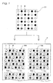
- a first misalignment verification pattern T20 and a second misalignment verification pattern T30 are printed on the printing paper P as misalignment verification patterns for determining these misalignment values (adjustment values) for the adjusting.
- the first misalignment verification pattern T20 comprises longitudinally aligned first gray patches T21-T25 (T23-T25 are not shown in Fig. 1).
- the second misalignment verification pattern T30 comprises second gray patches T31-T35 (T33-T35 are not shown in Fig. 1), which are formed on the right side of the first gray patches T21-T25, respectively, in the direction of main scanning. These two types of patches (quadrilateral printed images) are formed based on identical image data D1.
- the image data D 1 are print data for the yellow (Y), light-cyan (LC), and light-magenta (LM) dots shown in Fig. 1, and represent data related to images with an overall gray appearance.
- Yellow (Y), light-cyan (LC), and magenta (LM) dots are formed during the forward and reverse passes of main scans to form the first gray patches T21-T25.
- the dots are formed solely during the forward passes of main scans when the second gray patches T31-T35 are formed.
- the arrow signs underneath the Y, C, and M circles depicting the dots in Fig. 1 show the orientation of main scanning for recording the dots.
- the ink drops move through the air in different directions on the forward and reverse passes of main scanning because the print head varies its orientation. For this reason, the dots recorded on a forward pass and the dots recorded on a reverse pass have different dot formation positions for the first gray patches T21 and T22 in Fig. 1.
- the second gray patches T31 and T32 are obtained by recording dots during forward passes alone, so the misalignment of dots in the gray patches T31-T35 is more uniform than in the first gray patches T21 and T22.
- the gray patches T21-T25 of the first misalignment verification pattern T20 are printed by slightly varying the timing with which ink drops are ejected during reverse passes. Dot formation positions will therefore be misaligned differently in each of the gray patches T21-T25.
- the misalignment value of a timing that allows ink drops to be ejected with minimal dot formation misalignment can be set by selecting a patch whose print results are the closest to those delivered by the adjacently printed gray patches T31-T35 of the second misalignment verification pattern T30. This misalignment value can serve as an adjustment value for removing dot formation misalignments.
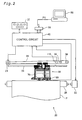
- Fig. 2 is a schematic block diagram of a printing system equipped with an ink-jet printer 20 as a working example.
- the printer 20 comprises a sub-scanning mechanism for transporting printing paper P in the direction of sub-scanning by means of a paper feed motor 22, a main scanning mechanism for reciprocating a carriage 30 in the axial direction (direction of main scanning) of a platen 26 by means of a carriage motor 24, a head drive mechanism for ejecting ink and forming dots by actuating a print head unit 60 mounted on the carriage 30, and a control circuit 40 for controlling exchanging signals among the paper feed motor 22, the carriage motor 24, the print head unit 60, and a control panel 32.
- the control circuit 40 is connected via a connector 56 to the computer 88.
- the sub-scanning mechanism for transporting the printing paper P comprises a gear train (not shown) for transmitting the rotation of the paper feed motor 22 to the platen 26 and a roller (not shown) for transporting the printing paper.
- the main scanning mechanism for reciprocating the carriage 30 comprises a sliding shaft 34 mounted parallel to the axis of the platen 26 and designed to slidably support the carriage 30, a pulley 38 for extending an endless drive belt 36 from the carriage motor 24, and a position sensor 39 for sensing the original position of the carriage 30.
- Fig. 3 is a block diagram depicting the structure of a printer 20, chiefly the control circuit 40.
- the control circuit 40 is designed as an arithmetic Boolean circuit comprising a CPU 41, a programmable ROM (PROM) 43, a RAM 44, and a character generator (CG) 45 containing dot matrices for characters.
- the control circuit 40 further comprises a dedicated I/F circuit 50 for creating a dedicated interface with external motors and the like, a head drive circuit 52 connected to the dedicated I/F circuit 50 and designed to eject ink by actuating the print head unit 60, and a motor drive circuit 54 for actuating the paper feed motor 22 and carriage motor 24.
- the dedicated I/F circuit 50 contains a parallel interface circuit and is capable of receiving print signals PS from the computer 88 via the connector 56.
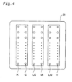
- Fig. 4 is a diagram depicting a plurality of nozzle rows provided to a print head 28.
- the printer 20 is a printing device for printing using inks of the following six colors: black (K), dark cyan (C), light cyan (LC), dark magenta (M), light magenta (LC), and yellow (Y).
- the printer is provided with a row of nozzles for each ink.
- Dark cyan and light cyan are cyan inks with substantially the same hues but different densities. The same applies to the dark magenta ink and light magenta ink.
- These nozzle rows correspond to "the single-color nozzle groups" referred to in the claims.
- the recording misalignments occurring during bidirectional printing are adjusted in accordance with the first working example described below.
- the first working example is not claimed, but is useful for understanding the present invention.
- the occurrence of a recording misalignment during bidirectional printing will be described herein before the first working example is described.
- the term "bidirectional printing” refers to a printing method in which main scans are performed in both directions, and dots are formed on a print medium both on the forward passes and on the reverse passes of main scanning to print images.
- unidirectional printing is reserved for a printing medium in which dots are formed on a print medium solely during the forward or reverse passes of main scanning to print images.
- Fig. 5 is a diagram depicting a misalignment occurring during bidirectional printing.
- Fig. 5A is a diagram depicting an impact position occupied by a dot on a forward pass during printing
- Fig. 5B is a diagram depicting an impact position occupied by a dot on a reverse pass during printing.
- a nozzle n forms dots on the printing paper P by moving horizontally in two directions over the printing paper P and ejecting ink on the forward and reverse passes. It is assumed that the ink is ejected vertically downward at an ejection velocity Vk.
- the combined velocity vector CVk of each ink is obtained by combining the downward ejection velocity vector and the main scan velocity vector Vs of nozzle n .
- the positions at which ink drops strike the print medium are misaligned when the ink drops are ejected while the printing paper P and the print head 28 (nozzle n ) are in the same positional relation on the forward and reverse passes during main scanning.
- the timing with which the ink drops are ejected on the forward and reverse passes during main scanning is adjusted in order to align the positions at which the ink drops strike the print medium.
- the dot formation misalignments are substantially symmetrical about the position occupied by nozzles during the ejection of ink drops on forward and reverse passes.
- factors that act to prevent the misalignment on the forward and reverse passes from being completely symmetrical such as the backlash of the drive mechanism for main scanning and the warping of the platen that supports the print medium from below.
- the timing with which ink drops are ejected on the forward and reverse passes during main scanning should preferably be adjusted in order to absorb the dot formation misalignments caused by these factors.
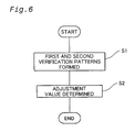
- Fig. 6 is a flowchart depicting the entire routine performed in accordance with the first working example.
- step S1 a first misalignment verification pattern and a second misalignment verification pattern are formed.
- step S2 the operator sets an adjustment value on the basis of the first and second misalignment verification patterns, and enters the information into the printer 20. A detailed description of each step follows.
- Fig. 7 is a diagram depicting an example of a first misalignment verification pattern T20.
- a first misalignment verification pattern is printed by the printer 20.
- the first misalignment verification pattern T20 is composed of a plurality of gray patches T21-T25 printed on the forward and reverse passes by light-cyan, light-magenta, and yellow nozzle rows.
- Each gray patch is designed to reproduce the same color.
- each of the patches in Fig. 7 is shown as an aggregation of comparatively large dots, in reality the dots can be so small as to be virtually invisible to the eye.
- the term "gray patch" does not mean that a patch will always appear as having a gray color to the human eye. In other words, other colors might be visible under certain dot misalignment conditions.
- the dots of each color constituting each patch are recorded at the same position in the direction of main scanning in each patch on a forward pass. But on reverse passes, the dots of each color constituting each patch are recorded at the position shifted in the direction of main scanning sequentially in 8,8 ⁇ m (1/2880 ⁇ inch) increments for each patch. The dots of each color constituting each patch are shifted by a common value in each reverse pass. As a result, a plurality of gray patches T21-T25 are printed on the printing paper P such that there is a shift of 8,8 ⁇ m (1/2880 inch) between the relative positions of dots formed on forward passes and dots formed on reverse passes.
- auxiliary adjustment value The extent to which the dots of each gray patch are shifted on the reverse passes to that on the forward pass corresponds to "the auxiliary adjustment value" referred to in the claims.
- Numerals designating shift adjustment numbers are printed on the left side of gray patches T21-T25, as shown in Fig. 7.
- the shift adjustment numbers function as correction-related information about the preferred correction state.
- the term "preferred correction state" refers to a state in which the grainy feel of a gray patch is minimized when the recording positions (or recording timings) on forward and/or reverse passes are corrected with appropriate adjustment values. The preferred corrected condition can therefore be actualized by such appropriate adjustment values.
- Fig. 7 illustrates five gray patches T21-T25, which are provided with shift adjustment numbers from 1 to 5 and are centered around a gray patch T23 labeled with the numeral "3."
- the gray patch T24 with a shift adjustment number of 4 illustrates a preferred correction state of minimal graininess.
- the gray patches T21-T25 are designed to reproduce mutually equal colors and are formed based on identical print data D1.
- the print data D1 that form the basis for the gray patches T21-T25 are obtained by a process in which color image data for expressing aggregated pixels of uniform density are converted to data for expressing the recording conditions of dots having a plurality of ink colors.
- the print data D 1 are stored on a hard disk (storage unit) in the computer 88.
- the gray patches T21-T25 are printed in step S 1 in accordance with a sub-scanning pattern for actual printing. The corresponding feed method is described below.
- the gray patches T21-T25 are formed while the CPU 41 controls the units comprising the ink-jet printer 20. In other words, the CPU 41 functions as "the first patch-forming unit" referred to in the claims.
- Fig. 8 is a plan view depicting the first misalignment verification pattern T20 and second misalignment verification pattern T30 on the printing paper P.
- Gray patches T31-T35 are formed in a corresponding one-on-one relationship on the right side of the gray patches T21-T25 constituting the first misalignment verification pattern T20.
- the gray patches T31-T35 are formed from the same ink as that used for the gray patches T21-T25 on the basis of the same print data D1 as that used for the gray patches T21-T25.
- the gray patches T31-T35 can thus reproduce the same colors as those adopted for the gray patches T21-T25.
- the only difference is that the gray patches T31-T35 are printed solely on the forward passes of main scanning.
- the gray patches T31-T35 constitute the second misalignment verification pattern T30. Since the gray patches T31-T35 are printed on forward passes alone, the timings according to which ink drops are ejected to form dots are not shifted relative to each other in the manner encountered with the gray patches T21-T25.
- the gray patches T31-T35 are also formed while the CPU 41 controls the constituent units of the ink-jet printer 20. In other words, the CPU 41 functions as "the second patch-forming unit" referred to in the claims.
- Fig. 9 is a diagram illustrating the manner in which the print head is advanced and dots are recorded during each main scan during the printing of the first and second misalignment verification patterns.
- the nozzle pitch k between the nozzles is 4.
- the term "nozzle pitch” is a value equal to the number of raster lines (that is, pixels) constituting the interval between the nozzles on the print head in the direction of sub-scanning.
- the pitch k is equal to 4 when three-raster lines can be placed between two nozzles.
- raster line refers to pixels arranged in a row in the direction of main scanning.
- pixel refers to a square on an imaginary grid drawn on a print medium in order to define the positions at which dots are to be recorded on the print medium.
- a circle in row 1 refers to the recording of dots on the first misalignment verification pattern T20 during the corresponding main scan
- a circle in row 2 refers to the recording of dots on the second misalignment verification pattern T30 during the corresponding main scan.
- misalignment verification pattern T20 is recorded on the forward and reverse passes of main scanning
- second misalignment verification pattern T30 is simultaneously recorded on the forward passes of main scanning.
- Idle recording periods and periods during which the first misalignment verification pattern T20 is recorded appear alternately every other full main scan (every two main scans).
- idle recording periods and periods during which the second misalignment verification pattern T30 is recorded appear alternately with every main scan.
- Neither misalignment verification pattern is recorded during main scans that are multiples of four.
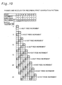
- Fig. 10 depicts only those passes shown in Fig. 9 during which the first misalignment verification pattern T20 is recorded.
- the first misalignment verification pattern T20 is such that dots are recorded on the first, second, fifth, sixth, and other main scans, as shown in Fig. 10. Of these, first, fifth, and any other main scan whose number is greater by one than a multiple of four are forward passes, and second, sixth, and any other main scan whose number is greater by two than a multiple of four are reverse passes.
- each of the raster lines in the first misalignment verification pattern T20 contains elements recorded on forward passes by the two corresponding nozzles and elements recorded on reverse passes by the two corresponding nozzles, alternated in the direction of sub-scanning (see Fig. 1).
- feed patterns are performed such that the system is fed in three-dot increments in the direction of sub-scanning during every pass of main scanning.
- the first misalignment verification pattern T20 is printed according to a pattern substantially identical to a repeating pattern of sub-scan feed increments when images are printed after the adjustment values have been determined.
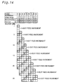
- Fig. 11 depicts only those passes shown in Fig. 9 during which the second misalignment verification pattern T30 is recorded.
- the second misalignment verification pattern T30 is such that dots are recorded on the first, third, fifth, seventh, and other main scans, as shown in Fig. 11. All these main scans are forward passes. Consequently, all the raster lines of the second misalignment verification pattern T30 are recorded by the two corresponding nozzles on forward passes (see Fig. 1).
- step S2 the user analyzes test patterns printed as shown in Fig. 8 and selects the gray patch T24 with minimal graininess from the gray patches T21-T25 of the first misalignment verification pattern T20.
- a comparison is made with the gray patches T31-T35 of the adjacently printed second misalignment verification pattern T30, and the gray patch with the closest printing results is selected.
- the shift adjustment number thereof is entered on the user interface screen (not shown) of the printer driver in the computer 88 (see Fig. 3).
- the shift adjustment number is stored in the PROM 43 of the printer 20.
- the shift value associated with the shift adjustment number stored in the PROM 43 is "the adjustment value" referred to in the claims.
- the input device (keyboard, mouse, microphone, or the like) of the computer 88 corresponds to "the input unit" referred to in the claims
- the below-described adjustment number storage area 202 of the PROM 43 corresponds to an adjustment value storage unit.
- the shift adjustment number may also be entered via the control panel 32 (see Fig. 3). In this case, the control panel 32 corresponds to the input unit.
- Fig. 12 is a block diagram depicting the principal structure related to misalignment correction during bidirectional printing in the first working example.
- the PROM 43 of the printer 20 comprises the adjustment number storage area 202 and an adjustment value table 206.
- Shift adjustment numbers that express preferred adjustment values are stored in the adjustment number storage area 202.
- the adjustment value table 206 is a table for storing the relation between the shift adjustment numbers and the extent (that is, the adjustment values) to which the dot recording positions of a reverse pass are shifted on the first misalignment verification pattern T20 shown in Figs. 7 and 8.
- the adjustment values are set to integral multiples of 8,8 ⁇ m (1/2880 inch) in the direction of main scanning in the above-described manner, the corresponding recording positions (that is, recording timing) can be adjusted in 8,8 ⁇ m (1/2880 ⁇ inch) increments in the direction of main scanning.
- the correction values can be set to an integral multiple of a smaller unit as long as the dots of each color in each of the patches T21-T25 (see Figs. 7and 8) are shifted at intervals that correspond to this smaller unit.
- the correction values can be set within a narrower range if smaller increments are adopted for the shifting between the positions of dots printed on a reverse pass.
- the minimum increment value is determined by the control limitations of the printer.
- second color patches (gray patches T31-T35) printed solely during forward passes and accordingly devoid of the dot formation misalignments resulting from bidirectional printing
- first color patches (gray patches T21-T25) printed on the forward and reverse passes of main scanning and made to correspond to adjustment values.
- First color patches with minimal dot formation misalignments can be easily selected by comparing mutually adjacent color patches and selecting first color patches whose print quality is the closest to that of the second color patches. It is not necessarily easy for the user to visually select a patch with minimal graininess from the lineup of a large number of patches. In particular, it is difficult to compare the graininess levels of patches located at a distance from each other.
- patches T31-T35 (which, theoretically, are free from dot formation misalignments on forward passes, as described above) can be printed nearby, and patches with the closest print results can be selected by comparison therewith. An adjustment value that yields the best print results can thus be easily obtained.
- the first working example was described with reference to a case in which the second misalignment verification pattern comprised a plurality of color patches (gray patches T31-T35), it is also possible to adopt an arrangement in which the second misalignment verification pattern is composed of an integral color patch rather than a plurality of separate color patches. Specifically, at least part of the second misalignment verification pattern should contain components comparable with the first color patches. Adopting such a structure allows a plurality of first color patches to be contrasted with portions equivalent to the corresponding second misalignment verification pattern, and a first color patch with high-quality print results to be selected.
- first color patches T21-T25 and second color patches T31-T35 are printed while aligned in the direction of main scanning. It is therefore possible to reduce the size of the area occupied by the first and second misalignment verification patterns T30 in the direction of sub-scanning on printing paper. A larger number of first color patches (which are equivalent to the corresponding auxiliary adjustment values) can therefore be formed on a sheet of printing paper with the same size.
- gray patches are printed and adjustment values are set using the light cyan, light magenta, and yellow inks commonly used to print grainy halftones. It is therefore possible to make such halftones less grainy and to improve the image quality of print results.
- the gray patches T21-T25 are printed by feeding the system substantially the same way as when the system is sub-scanned and fed during actual color printing. It is therefore possible to determine the adjustment values needed to reduce the graininess of print results during actual color printing.
- color patches are formed based on the same image data by bidirectional printing and unidirectional printing, the two are compared, bidirectionally printed patterns whose print results have the highest quality are selected, and adjustment values are set.
- color patches are formed based on two separate types of image data about each adjustment value, and adjustment values capable of delivering adequate print results are determined for both images. Separate descriptions are given below for bidirectional printing and unidirectional printing.
- Fig. 13 is a plan view depicting a first misalignment verification pattern T20 and a second misalignment verification pattern T40 on printing paper P.
- the first misalignment verification pattern T20 and second misalignment verification pattern T40 are formed on printing paper P in the same manner as shown in Fig. 8, but the content of the second misalignment verification pattern T40 is different from the one considered in the first working example.
- the patches of the second misalignment verification pattern T40 are formed by a procedure in which ink drops are ejected on the forward and reverse passes of main scanning on the basis of print data D2 for a uniformly dense beige color. These are formed adjacent (at a position aligned in the direction of main scanning) to the corresponding gray patches T21-T25.
- the gray patches T21-T25 correspond to the "first color patches" referred to in the claims.
- These uniformly dense beige patches T41-T45 are formed by shifting the dot formation positions in 8,8 ⁇ m (1/2880 ⁇ inch) increments in the same manner as in the case of the gray patches T21-T25.
- the beige patches T41-T45 correspond to the "second color patches" referred to in the claims.
- the shift in the dot formation positions of the beige patches T41-T45 is equal to the shift in the dot formation positions of the mutually adjacent gray patches T21-T25.
- the shift of the beige patches T41-T45 corresponds to "the auxiliary adjustment values" referred to in the claims.
- the beige patches T41-T45 are formed using a plurality of mutually different auxiliary adjustment values.
- the gray patches T21-T25 and beige patches T41-T45 are formed during the same main scan at positions aligned in the direction of main scanning.
- Fig. 14 is a diagram illustrating the manner in which the print head is advanced and dots are recorded during each main scan during the printing of the first misalignment verification pattern T20 and second misalignment verification pattern T40 according to the second working example.
- the print head is advanced in the manner shown in Fig. 14 because there is no need to perform a main scan in two forward passes for each raster line (in order to print the second misalignment verification pattern T40).
- a sub-scan involving a three-dot feed is performed between each pair of main scans on a forward or reverse pass.
- This feed pattern is identical to the feed pattern performed when the system is sub-scanned and fed during the printing of actual images after the adjustment values have been set.
- the user visually examines the test pattern printed in step S2 (see Fig. 6) and selects a combination of gray and beige patches aligned in the direction from left to right. In the process, the user selects a combination that has minimal graininess for both the gray and beige patches.
- the adjustment number of the combination is entered into the printer 20.
- the shift adjustment number is stored in the adjustment number storage area 202 (see Fig. 12) of the printer 20 in the same manner as in the first working example.
- two types of patches (beige patches T41-T45 and gray patches T21-T25) are formed for each auxiliary adjustment value.
- the gray patches T21-T25 and beige patches T41-T45 are formed during the same main scan at positions aligned in the direction of main scanning.
- the shifts can therefore be equalized, there is no need to adopt variable shifting for the timing with which ink drops are ejected during a main scan, and the control procedure can be facilitated.
- gray patches T21-T25 and beige patches T41-T45 are formed by bidirectional printing, and adjustment values are set for adjusting the dot formation misalignments on the forward and reverse passes of bidirectional printing.
- the present invention can also be adapted to the adjustment of dot formation misalignments between nozzles during unidirectional printing. For example, actuator chips might be affected by manufacturing errors, and mounting errors might also occur during the mounting of the print head on the carriage. For this reason, each nozzle deposits ink drops at a slightly different position (dot formation position) even when the drops are ejected during the same main scan. Adopting an arrangement such as the one described below can help adjust such dot formation misalignments in these cases as well.
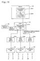
- Fig. 15 is a block diagram depicting the principal structure related to the misalignment correction of the printing procedure adopted in the second working example.
- This block diagram has the same structure as the block diagram of Fig. 12 for all of its elements except the head drive circuit and the actuator chip structure.
- the printing device shown in Fig. 15 is designed for unidirectional printing.
- the printing device also comprises a head drive circuit 52c that is separate from the other actuator chips and is used with the actuator chip 93 for actuating light magenta and yellow nozzle rows. It is therefore possible to shift the ejection timing of the light magenta and yellow nozzle rows in relations to the inks of other colors.
- the printing device of the second working example also has separate head drive circuits 52a and 52b for use with the actuator chip 91 for actuating black and cyan nozzle rows, and the actuator chip 92 for actuating light cyan and magenta nozzle rows, respectively.
- the other features are the same as those of the printing device pertaining to the first working example.
- Such a printer is used to form the uniformly dense gray patches T21-T25 and beige patches T41-T45 in an aligned arrangement, as shown in Fig. 13.
- Each patch is formed by unidirectional printing.
- the light magenta and yellow dots in the gray patches T21-T25 are formed while slightly shifted relative to the dots of other colors.
- the shifting of each patch differs by 8,8 ⁇ m (1/2880 inch).
- the light magenta and yellow dots in the beige patches T41-T45 are also formed while slightly shifted relative to the dots of other colors.
- the dots are shifted to the same extent as the dots of the adjacent gray patches located on the left.
- the user visually examines the print results, selects a combination of gray and beige patches that have minimal graininess, and inputs the corresponding adjustment number into the printer 20.
- a misalignment-correcting unit 210 retrieves the adjustment number from the adjustment number storage area 202 and obtains the corresponding adjustment value from the adjustment value table 206 during image printing.
- the head drive circuit 52c is presented with a signal for specifying the head recording timing on the basis of the adjustment value.
- the head drive circuits for driving other nozzle rows are not provided with any signals for correcting dot formation positions. As a result, light magenta and yellow dot formation positions are adjusted relative to the dots of other colors. Adopting this approach makes it possible to adjust dot formation misalignments among nozzles during unidirectional printing.
- first color patches are formed by bidirectional printing
- second color patches are formed by unidirectional printing.
- the second working example involves forming patches of different colors (gray and beige). It is also possible to adopt any other arrangement as long as the second color patches differ from the first color patches either in terms of color or in terms of printing method.
- An example of an arrangement in which different printing methods are used is one in which different feed patterns are used for sub-scanning during the formation of first and second color patches. Adopting this arrangement makes it possible to compare the first and second color patches and to set an adjustment value that improves the quality (reduces the graininess) of print results for a plurality of types of feed patterns employed during sub-scanning.
- first color patches with relatively large dots
- second color patches with relatively small dots. Adopting this arrangement makes it possible to determine an adjustment value capable of yielding adequate print results with images represented by the dots of corresponding sizes.
- a single adjustment value can also be used to print three types of color patches (color patches formed with comparatively large dots, color patches formed with comparatively small dots, and color patches formed with both comparatively large and comparatively small dots), and to determine the desired adjustment values with consideration for the print quality of each type of patch.
- the phrase "different printing methods" can refer to any arrangement in which some aspect of printing is varied while the underlying image data remain the same.
- Fig. 16 is a plan view depicting a first misalignment verification pattern T20a and a second misalignment verification pattern T30a on printing paper P according to a modification.
- An adjustment value can be set with consideration for the quality degradation of print results due to errors affecting sub-scanning/feeding if the patches are extended in the direction of sub-scanning, as shown in Fig. 16.
- the patches T21a-T25a and T31a-T35a should preferably be formed across at least one fourth of the printable area on the printing paper in the direction perpendicular to the direction of main scanning.
- Forming the patches within this range allows these patches to fully reflect the errors affecting sub-scanning feed when images are printed in the printable area.
- a smaller number of patches can be formed on a single sheet of printing paper, but forming the patches on a plurality of sheets of printing paper makes it possible to form such patches with substantially the same number of auxiliary adjustment values as in the first or second working example.
- Print area is an area in which the printer can form images on a print medium.
- the printable area has limitations in terms of mechanical structure, control method, or other printer attributes.
- the mechanical structure, control method, or other printer attributes sometimes prevent images from being printed on a sheet of printing paper with a 15-mm upper margin, a 10-mm lower margin, and 5-mm side margins.
- the printable area is the inside area of a sheet of printing paper with a 15-mm upper margin, a 10-mm lower margin, and 5-mm side margins.
- Such printable areas may, for example, be described in printer manuals.
- Information about printable area settings is sometimes displays in the driver settings window on the computer display. The printable area occupies the entire print medium if images can be formed over the entire print medium.
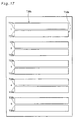
- Fig. 17 is a plan view depicting a first misalignment verification pattern T20b and a second misalignment verification pattern T30b on the printing paper P according to another modification.
- An adjustment value can be set with consideration for the quality degradation of print results due to errors affecting main scanning feed if the patches are extended in the direction of main scanning, as shown in Fig. 17.
- the patches T21b-T25b and T31b-T35b should preferably be formed across at least half of the printable area on the printing paper in the direction of main scanning. Forming the patches within this range allows these patches to fully reflect the errors affecting main scanning feed when images are printed in the printable area.
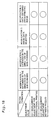
- Fig. 18 is a table that lists combinations of modifications and types of misalignments to be adjusted with adjustment values.
- adjustment values were determined for adjusting dot formation misalignments on the forward and reverse passes of a main scan during bidirectional printing.
- adjustment values were determined for adjusting dot formation misalignments between the nozzles.
- the above modifications may also be used to set up adjustment values for the dot formation misalignments of bidirectional printing in the manner adopted for the first working example, or to set up adjustment values for the dot formation misalignments between the nozzles in the manner adopted for (2) of the second working example, as shown in Fig. 18.
- the present invention can be adapted to ink-jet printers and various other image output devices for outputting images by employing dots.
Claims (15)
- Verfahren zum Bestimmen eines Einstellwertes zur Verringerung von Punktausbildungsfehlausrichtungen in Richtung einer Hauptabtastung während eines Prozesses, bei dem eine Druckvorrichtung (20), die mit mehreren monochromatischen Düsengruppen zum Ausstoßen von Tintentropfen von unterschiedlichen Farben versehen ist, verwendet wird, um Bilder durch Abscheiden von Tintentropfen auf ein Druckmedium und Ausbilden von Punkten zu drucken, während die Hauptabtastung durchgeführt wird, um die monochromatischen Düsengruppen und/oder das Druckmedium zu bewegen, wobei das Verfahren zum Bestimmen eines Einstellwerts die folgenden Schritte aufweist:(a) Ausbilden mehrerer erster Farbflecken (T21-T25) auf einem Druckmedium für jeweilige mehrere Hilfseinstellwerte, wobei die ersten Farbflecken jeweils auf der Grundlage von identischen ersten Druckdaten (D1) ausgebildet werden, um eine gemeinsame identische erste Farbe zu reproduzieren, die durch Punkte ausgebildet wird, die aus zwei oder mehr Typen von Tinte zusammengesetzt sind,
gekennzeichnet durch(b) Ausbilden mehrerer zweiter Farbflecken (T41-T45) auf einem Druckmedium für die jeweiligen Hilfseinstellwerte durch dasselbe Druckschema wie dasjenige, das verwendet wird, um die ersten Farbflecken zu drucken, wobei die zweiten Farbflecken jeweils auf der Grundlage von identischen zweiten Druckdaten (D2) ausgebildet werden, um eine gemeinsame identische zweite Farbe zu reproduzieren, die durch Punkte ausgebildet wird, die aus zwei oder mehr Typen von Tinte zusammengesetzt sind, wobei sich die zweite Farbe von der ersten Farbe unterscheidet, und(c) Auswählen des Einstellwertes aus den Hilfseinstellwerten auf der Grundlage der ersten Farbflecken und der zweiten Farbflecken. - Verfahren zum Bestimmen eines Einstellwertes nach Anspruch 1, wobei die erste Farbe grau und die zweite Farbe beige ist.
- Verfahren zum Bestimmen eines Einstellwertes nach Anspruch 1 oder 2, wobei der Schritt (b) den folgenden Schritt aufweist:Ausbilden der zweiten Farbflecken an Positionen, die in Richtung der Hauptabtastung in Bezug auf die ersten Farbflecken ausgerichtet sind.
- Verfahren zum Bestimmen eines Einstellwertes nach Anspruch 1 oder 2, wobei der Schritt (a) den folgenden Schritt aufweist:Ausbilden jedes der ersten Farbflecken über mindestens ein Viertel eines druckbaren Bereichs auf dem Druckmedium in einer Richtung.senkrecht zur Richtung der Hauptabtastung, undwobei der Schritt (b) den folgenden Schritt aufweist:Ausbilden der zweiten Farbflecken über mindestens ein Viertel des druckbaren Bereichs auf dem Druckmedium in Richtung senkrecht zur Richtung der Hauptabtastung.
- Verfahren zum Bestimmen eines Einstellwertes nach einem der Ansprüche 1 bis 3, wobei der Schritt (a) den folgenden Schritt aufweist:Ausbilden der ersten Farbflecken über mindestens die Hälfte eines druckbaren Bereichs auf dem Druckmedium in Richtung einer Hauptabtastung, undwobei der Schritt (b) den folgenden Schritt aufweist:Ausbilden der zweiten Farbflecken über mindestens die Hälfte des druckbaren Bereichs auf dem Druckmedium in Richtung der Hauptabtastung.
- Druckvorrichtung zum Drucken von Bildern durch Ausstoßen von Tintentropfen von Düsen und Abscheiden von Tintentropfen auf ein Druckmedium (p), um Punkte auszubilden, die aufweist:mehrere monochromatische Düsengruppen zum Ausstoßen von Tintentropfen von jeweils unterschiedlichen einzelnen Farben,eine Hauptabtasteinheit (34, 38, 39), die ausgelegt ist, eine Hauptabtastung durch Bewegen der monochromatischen Düsengruppen und/oder des Druckmediums durchzuführen,eine Eingabeeinheit (88, 32), die ausgelegt ist, Daten, die von außerhalb eingegeben werden, zu empfangen, undeine Steuereinheit (40), die ausgelegt ist, ein Drucken zu steuern, wobei die Steuereinheit aufweist: eine erste Fleckenausbildungseinheit, die ausgelegt ist, mehrere erste Farbflecken (T21-T25) auf einem Druckmedium für jeweilige mehrere Hilfseinstellwerte auszubilden, wobei die ersten Farbflecken jeweils auf der Grundlage von identischen ersten Druckdaten ausgebildet werden, um eine gemeinsame identische erste Farbe zu reproduzieren, die durch Punkte ausgebildet wird, die aus zwei oder mehr Typen von Tinte zusammengesetzt sind,gekennzeichnet durch
eine zweite Fleckenausbildungseinheit, die ausgelegt ist, mehrere zweite Farbflecken (T41-T45) auf einem Druckmedium für die jeweiligen Hilfseinstellwerte durch dasselbe Druckschema wie dasjenige, das verwendet wird, um die ersten Farbflecken zu drucken, auszubilden, wobei die zweiten Farbflecken jeweils auf der Grundlage von identischen zweiten Druckdaten ausgebildet werden, um eine identische zweite Farbe zu reproduzieren, die durch Punkte ausgebildet wird, die aus zwei oder mehr Typen von Tinte zusammengesetzt sind, wobei sich die zweite Farbe von der ersten Farbe unterscheidet, und
eine Einstellwertspeichereinheit (202), die ausgelegt ist, einen Einstellwert, der auf der Grundlage der ersten Farbflecken und der zweiten Farbflecken aus den Hilfseinstellwerten ausgewählt und in die Eingabeeinheit (88, 32) eingegeben wird, zu speichern. - Druckvorrichtung nach Anspruch 6, wobei die erste Farbe grau und die zweite Farbe beige ist.
- Druckvorrichtung nach Anspruch 6 oder 7, wobei
die zweite Fleckenausbildungseinheit die zweiten Farbflecken an Positionen ausbildet, die in Richtung der Hauptabtastung in Bezug auf die ersten Farbflecken ausgerichtet sind. - Druckvorrichtung nach Anspruch 6 oder 7, wobei
die erste Fleckenausbildungseinheit jeden der ersten Farbflecken über mindestens ein Viertel eines druckbaren Bereichs des Druckmediums in einer Richtung senkrecht zur Richtung der Hauptabtastung ausbildet, und
die zweite Fleckenausbildungseinheit die zweiten Farbflecken über mindestens ein Viertel des druckbaren Bereichs auf dem Druckmedium in der Richtung senkrecht zur Richtung der Hauptabtastung ausbildet. - Druckvorrichtung nach einem der Ansprüche 6 bis 8, wobei
die erste Fleckenausbildungseinheit die ersten Farbflecken über mindestens die Hälfte eines druckbaren Bereichs auf dem Druckmedium in der Richtung der Hauptabtastung ausbildet, und
die zweite Fleckenausbildungseinheit den zweiten Farbflecken über mindestens die Hälfte des druckbaren Bereichs auf dem Druckmedium in der Richtung der Hauptabtastung ausbildet. - Computerprogrammprodukt, das ausgelegt ist, zu ermöglichen, dass Fehlausrichtungsverifizierungsmuster zum Bestimmen eines Einstellwerts, der verwendet werden kann, um Punktausbildungsfehlausrichtungen während des Druckens zu verringern, von einem Computer ausgebildet werden, der eine Druckeinheit mit mehreren monochromatischen Düsengruppen zum Ausstoßen von Tintentropfen von unterschiedlichen Farben aufweist, wobei das Computerprogrammprodukt derart ausgelegt ist, dass der Einstellwert ausgelegt ist, Punktausbildungsfehlausrichtungen in einer Richtung einer Hauptabtastung während eines Prozesses zu verringern, bei dem Bilder durch Abscheiden von Tintentropfen auf einem Druckmedium und Ausbilden von Punkten gedruckt werden, während die Hauptabtastung durchgeführt wird, um die monochromatischen Düsengruppen und/oder das Druckmedium zu bewegen,
wobei das Computerprogrammprodukt aufweist:ein computerlesbares Medium, undComputerprogramme, die auf dem computerlesbaren Medium gespeichert sind,und wobei die Computerprogramme aufweisen:ein erstes Programm zum Bewirken, dass der Computer mehrere erste Farbflecken (T21-T25) auf einem Druckmedium für jeweilige mehrere Hilfseinstellwerte ausbildet, wobei die ersten Farbflecken jeweils auf der Grundlage von identischen ersten Druckdaten ausgebildet werden, um eine gemeinsame identische erste Farbe zu reproduzieren, die durch Punkte ausgebildet wird, die aus zwei oder mehr Typen von Tinte zusammengesetzt sind,gekennzeichnet durch
ein zweites Programm zum Bewirken, dass der Computer mehrere zweite Farbflecken (T41-T45) auf einem Druckmedium für die jeweiligen Hilfseinstellwerte durch dasselbe Druckschema wie dasjenige, das verwendet wird, , um die ersten Farbflecken zu drucken, ausbildet, wobei die zweiten Farbflecken jeweils auf der Grundlage von identischen zweiten Druckdaten ausgebildet werden, um eine gemeinsame identische zweite Farbe zu reproduzieren, die durch Punkte ausgebildet wird, die aus zwei oder mehr Typen von Tinte zusammengesetzt sind, wobei sich die zweite Farbe von der ersten Farbe unterscheidet, und
ein drittes Programm zum Bewirken, dass der Computer den Einstellwert, der auf der Grundlage der ersten Farbflecken und der zweiten Farbflecken aus den Hilfseinstellwerten ausgewählt und in die Eingabeeinheit (88, 32) eingegeben wird, speichert. - Computerprogrammprodukt nach Anspruch 11, wobei die erste Farbe grau und die zweite Farbe beige ist.
- Computerprogrammprodukt nach Anspruch 12, wobei das zweite Programm aufweist:ein Programm zum Bewirken, dass der Computer die zweiten Farbflecken an Positionen ausbildet, die in der Richtung der Hauptabtastung in Bezug auf die ersten Farbflecken ausgerichtet sind.
- Computerprogrammprodukt nach Anspruch 11 oder 12, wobei das erste Programm aufweist:ein Programm zum Bewirken, dass der Computer jedes der ersten Farbflecken über mindestens ein Viertel eines druckbaren Bereichs auf dem Druckmedium in einer Richtung der Hauptabtastung ausbildet, unddas zweite Programm aufweist:ein Programm zum Bewirken, dass der Computer die zweiten Farbflecken über mindestens ein Viertel des druckbaren Bereichs auf dem Druckmedium in der Richtung senkrecht zur Richtung der Hauptabtastung ausbildet.
- Computerprogrammprodukt nach einem der Ansprüche 11 bis 13, wobei das erste Programm aufweist:ein Programm zum Bewirken, dass der Computer die ersten Farbflecken über mindestens die Hälfte eines druckbaren Bereichs auf dem Druckmedium in der Richtung der Hauptabtastung ausbildet, unddas zweite Programm aufweist:ein Programm zum Bewirken, dass der Computer den zweiten Farbfleck über mindestens die Hälfte des druckbaren Bereichs auf dem Druckmedium in der Richtung der Hauptabtastung ausbildet.
Applications Claiming Priority (3)
| Application Number | Priority Date | Filing Date | Title |
|---|---|---|---|
| JP2000224896A JP3972561B2 (ja) | 2000-07-26 | 2000-07-26 | 複数種類の検査用パターンを使用して行う印刷時の記録位置ずれの調整値の決定 |
| JP2000224896 | 2000-07-26 | ||
| PCT/JP2001/006474 WO2002007983A1 (fr) | 2000-07-26 | 2001-07-26 | Determination de la valeur de d'ajustement pour l'enregistrement de la deviation de position dans l'impression au moyen d'une pluralite de types de modeles d'inspection |
Publications (3)
| Publication Number | Publication Date |
|---|---|
| EP1221380A1 EP1221380A1 (de) | 2002-07-10 |
| EP1221380A4 EP1221380A4 (de) | 2003-05-21 |
| EP1221380B1 true EP1221380B1 (de) | 2006-05-17 |
Family
ID=18718759
Family Applications (1)
| Application Number | Title | Priority Date | Filing Date |
|---|---|---|---|
| EP01984319A Expired - Lifetime EP1221380B1 (de) | 2000-07-26 | 2001-07-26 | Bestimmung des einstellwertes für eine aufzeichnungspositionsabweichung beim drucken unter verwendung mehrerer arten von inspektionsmustern |
Country Status (6)
| Country | Link |
|---|---|
| US (1) | US6672701B1 (de) |
| EP (1) | EP1221380B1 (de) |
| JP (1) | JP3972561B2 (de) |
| AT (1) | ATE326351T1 (de) |
| DE (1) | DE60119684T2 (de) |
| WO (1) | WO2002007983A1 (de) |
Families Citing this family (11)
| Publication number | Priority date | Publication date | Assignee | Title |
|---|---|---|---|---|
| ATE318714T1 (de) * | 2001-11-06 | 2006-03-15 | Canon Kk | Tintenstrahldruckvorrichtung und korrekturverfahren für ein bild |
| US6863374B2 (en) | 2002-04-16 | 2005-03-08 | Seiko Epson Corporation | Image printing using print quality enhancing ink |
| JP4284942B2 (ja) | 2002-08-20 | 2009-06-24 | セイコーエプソン株式会社 | 印刷装置、コンピュータプログラム、コンピュータシステム、及び、補正用パターンの製造方法 |
| EP1418053B1 (de) * | 2002-11-06 | 2007-10-03 | Océ-Technologies B.V. | Verfahren zum Verbessern der Bildrandqualität |
| JP2004155192A (ja) | 2002-11-06 | 2004-06-03 | Oce Technol Bv | 印刷方法 |
| JP4164336B2 (ja) * | 2002-11-12 | 2008-10-15 | キヤノン株式会社 | 画像濃度確認チャート及び画像濃度確認方法 |
| US7374269B2 (en) * | 2004-09-30 | 2008-05-20 | Lexmark International, Inc. | Methods for determining unidirectional print direction for improved quality |
| US7100508B1 (en) * | 2005-02-25 | 2006-09-05 | Eastman Kodak Company | Color registration test pattern |
| US7390073B2 (en) * | 2005-07-29 | 2008-06-24 | Lexmark International, Inc. | Method and apparatus for performing alignment for printing with a printhead |
| US7709402B2 (en) * | 2006-02-16 | 2010-05-04 | Micron Technology, Inc. | Conductive layers for hafnium silicon oxynitride films |
| US9782978B2 (en) | 2014-05-29 | 2017-10-10 | Hewlett-Packard Development Company, L.P. | Serpentine direction reversal in bidirectional error diffusion halftoning |
Family Cites Families (8)
| Publication number | Priority date | Publication date | Assignee | Title |
|---|---|---|---|---|
| JPH0569625A (ja) | 1991-09-11 | 1993-03-23 | Seiko Epson Corp | シリアル・プリンタ装置 |
| ATE225540T1 (de) | 1993-05-27 | 2002-10-15 | Canon Kk | Verfahren und vorrichtung zur tintenstrahlaufzeichnung |
| JP3444937B2 (ja) | 1993-09-20 | 2003-09-08 | キヤノン株式会社 | インクジェットプリント方法及びインクジェット記録装置 |
| US5598272A (en) * | 1994-04-07 | 1997-01-28 | Imation, Inc. | Visual calibrator for color halftone imaging |
| US6164749A (en) * | 1997-03-17 | 2000-12-26 | Hewlett-Packard Company | Method for user alignment of a color printer |
| US6310637B1 (en) | 1997-07-31 | 2001-10-30 | Seiko Epson Corporation | Method of printing test pattern and printing apparatus for the same |
| US6196736B1 (en) | 1998-08-18 | 2001-03-06 | Seiko Epson Corporation | Adjustment of printing position deviation during bidirectional printing |
| JP3744273B2 (ja) | 1999-08-03 | 2006-02-08 | セイコーエプソン株式会社 | 記録方法および記録装置、並びに、そのためのプログラムを記録した可読媒体 |
-
2000
- 2000-07-26 JP JP2000224896A patent/JP3972561B2/ja not_active Expired - Fee Related
-
2001
- 2001-07-26 EP EP01984319A patent/EP1221380B1/de not_active Expired - Lifetime
- 2001-07-26 AT AT01984319T patent/ATE326351T1/de not_active IP Right Cessation
- 2001-07-26 WO PCT/JP2001/006474 patent/WO2002007983A1/ja active IP Right Grant
- 2001-07-26 DE DE60119684T patent/DE60119684T2/de not_active Expired - Lifetime
- 2001-07-26 US US10/088,799 patent/US6672701B1/en not_active Expired - Fee Related
Also Published As
| Publication number | Publication date |
|---|---|
| WO2002007983A1 (fr) | 2002-01-31 |
| EP1221380A1 (de) | 2002-07-10 |
| JP3972561B2 (ja) | 2007-09-05 |
| DE60119684T2 (de) | 2007-04-26 |
| EP1221380A4 (de) | 2003-05-21 |
| ATE326351T1 (de) | 2006-06-15 |
| US6672701B1 (en) | 2004-01-06 |
| JP2002036531A (ja) | 2002-02-05 |
| DE60119684D1 (de) | 2006-06-22 |
Similar Documents
| Publication | Publication Date | Title |
|---|---|---|
| US6886904B2 (en) | Determination of adjustment value for recording misalignment during printing with two types test patterns | |
| US8118388B2 (en) | Adjustment of misalignments of recording positions during bidirectional printing | |
| US8240795B2 (en) | Printing method and printing apparatus | |
| US20060092221A1 (en) | Printing method and apparatus for an ink-jet printer having a wide printhead | |
| JP2011016377A (ja) | プラテンを汚すことなく印刷媒体の端部まで行う印刷 | |
| WO2001092020A1 (fr) | Reglage du decalage des positions de points d'une imprimante | |
| JP3837960B2 (ja) | 印刷装置、印刷方法および記録媒体 | |
| EP1221380B1 (de) | Bestimmung des einstellwertes für eine aufzeichnungspositionsabweichung beim drucken unter verwendung mehrerer arten von inspektionsmustern | |
| US6527359B1 (en) | Misregistration correction for bidirectional printing with reduced influence of error due to vertical scanning | |
| US11660877B2 (en) | Image processing apparatus, image processing method, and inkjet printing apparatus | |
| JP4154865B2 (ja) | 複数画素を階調再現の1単位とする印刷 | |
| US20050017999A1 (en) | Printing method, printing apparatus, computer-readable storage medium, and correction pattern | |
| JP5969236B2 (ja) | インク吐出量制御装置 | |
| JP4165048B2 (ja) | 印刷モードごとに異なる検査用パターンを使用して行うドット記録位置ずれの調整値の決定 | |
| JP2001334654A (ja) | 異なるタイミングで形成されるドット間の形成位置のずれの調整 | |
| US6886911B2 (en) | Apparatus for and method of compensating for image quality of inkjet printer | |
| JP4635374B2 (ja) | プラテンを汚すことなく印刷媒体の端部まで行う印刷 | |
| US20240001695A1 (en) | Printing device and printing method | |
| US6695422B1 (en) | Positional difference adjustment during printing with multiple types of drive signals | |
| US20130076815A1 (en) | Inkjet printer and printing method | |
| JP2023096573A (ja) | 記録装置および記録方法 | |
| US20040263871A1 (en) | High resolution printing method | |
| JP2002225248A (ja) | 複数種類の位置ずれ検査用パターンを使用して行う印刷時の記録位置ずれの調整値の決定 | |
| JP2016179585A (ja) | 印刷濃度の補正方法および印刷装置 | |
| JP2004181807A (ja) | インクジェット記録装置 |
Legal Events
| Date | Code | Title | Description |
|---|---|---|---|
| PUAI | Public reference made under article 153(3) epc to a published international application that has entered the european phase |
Free format text: ORIGINAL CODE: 0009012 |
|
| 17P | Request for examination filed |
Effective date: 20020319 |
|
| AK | Designated contracting states |
Kind code of ref document: A1 Designated state(s): AT BE CH CY DE DK ES FI FR GB GR IE IT LI LU MC NL PT SE TR |
|
| A4 | Supplementary search report drawn up and despatched |
Effective date: 20030409 |
|
| 17Q | First examination report despatched |
Effective date: 20040128 |
|
| GRAP | Despatch of communication of intention to grant a patent |
Free format text: ORIGINAL CODE: EPIDOSNIGR1 |
|
| GRAS | Grant fee paid |
Free format text: ORIGINAL CODE: EPIDOSNIGR3 |
|
| GRAA | (expected) grant |
Free format text: ORIGINAL CODE: 0009210 |
|
| AK | Designated contracting states |
Kind code of ref document: B1 Designated state(s): AT BE CH CY DE DK ES FI FR GB GR IE IT LI LU MC NL PT SE TR |
|
| PG25 | Lapsed in a contracting state [announced via postgrant information from national office to epo] |
Ref country code: IT Free format text: LAPSE BECAUSE OF FAILURE TO SUBMIT A TRANSLATION OF THE DESCRIPTION OR TO PAY THE FEE WITHIN THE PRESCRIBED TIME-LIMIT;WARNING: LAPSES OF ITALIAN PATENTS WITH EFFECTIVE DATE BEFORE 2007 MAY HAVE OCCURRED AT ANY TIME BEFORE 2007. THE CORRECT EFFECTIVE DATE MAY BE DIFFERENT FROM THE ONE RECORDED. Effective date: 20060517 Ref country code: LI Free format text: LAPSE BECAUSE OF FAILURE TO SUBMIT A TRANSLATION OF THE DESCRIPTION OR TO PAY THE FEE WITHIN THE PRESCRIBED TIME-LIMIT Effective date: 20060517 Ref country code: FI Free format text: LAPSE BECAUSE OF FAILURE TO SUBMIT A TRANSLATION OF THE DESCRIPTION OR TO PAY THE FEE WITHIN THE PRESCRIBED TIME-LIMIT Effective date: 20060517 Ref country code: NL Free format text: LAPSE BECAUSE OF FAILURE TO SUBMIT A TRANSLATION OF THE DESCRIPTION OR TO PAY THE FEE WITHIN THE PRESCRIBED TIME-LIMIT Effective date: 20060517 Ref country code: AT Free format text: LAPSE BECAUSE OF FAILURE TO SUBMIT A TRANSLATION OF THE DESCRIPTION OR TO PAY THE FEE WITHIN THE PRESCRIBED TIME-LIMIT Effective date: 20060517 Ref country code: CH Free format text: LAPSE BECAUSE OF FAILURE TO SUBMIT A TRANSLATION OF THE DESCRIPTION OR TO PAY THE FEE WITHIN THE PRESCRIBED TIME-LIMIT Effective date: 20060517 Ref country code: BE Free format text: LAPSE BECAUSE OF FAILURE TO SUBMIT A TRANSLATION OF THE DESCRIPTION OR TO PAY THE FEE WITHIN THE PRESCRIBED TIME-LIMIT Effective date: 20060517 |
|
| REG | Reference to a national code |
Ref country code: GB Ref legal event code: FG4D |
|
| REG | Reference to a national code |
Ref country code: CH Ref legal event code: EP |
|
| REG | Reference to a national code |
Ref country code: IE Ref legal event code: FG4D |
|
| REF | Corresponds to: |
Ref document number: 60119684 Country of ref document: DE Date of ref document: 20060622 Kind code of ref document: P |
|
| PG25 | Lapsed in a contracting state [announced via postgrant information from national office to epo] |
Ref country code: IE Free format text: LAPSE BECAUSE OF NON-PAYMENT OF DUE FEES Effective date: 20060726 |
|
| PG25 | Lapsed in a contracting state [announced via postgrant information from national office to epo] |
Ref country code: MC Free format text: LAPSE BECAUSE OF NON-PAYMENT OF DUE FEES Effective date: 20060731 |
|
| PG25 | Lapsed in a contracting state [announced via postgrant information from national office to epo] |
Ref country code: DK Free format text: LAPSE BECAUSE OF FAILURE TO SUBMIT A TRANSLATION OF THE DESCRIPTION OR TO PAY THE FEE WITHIN THE PRESCRIBED TIME-LIMIT Effective date: 20060817 Ref country code: SE Free format text: LAPSE BECAUSE OF FAILURE TO SUBMIT A TRANSLATION OF THE DESCRIPTION OR TO PAY THE FEE WITHIN THE PRESCRIBED TIME-LIMIT Effective date: 20060817 |
|
| PG25 | Lapsed in a contracting state [announced via postgrant information from national office to epo] |
Ref country code: ES Free format text: LAPSE BECAUSE OF FAILURE TO SUBMIT A TRANSLATION OF THE DESCRIPTION OR TO PAY THE FEE WITHIN THE PRESCRIBED TIME-LIMIT Effective date: 20060828 |
|
| PG25 | Lapsed in a contracting state [announced via postgrant information from national office to epo] |
Ref country code: PT Free format text: LAPSE BECAUSE OF FAILURE TO SUBMIT A TRANSLATION OF THE DESCRIPTION OR TO PAY THE FEE WITHIN THE PRESCRIBED TIME-LIMIT Effective date: 20061017 |
|
| NLV1 | Nl: lapsed or annulled due to failure to fulfill the requirements of art. 29p and 29m of the patents act | ||
| REG | Reference to a national code |
Ref country code: CH Ref legal event code: PL |
|
| ET | Fr: translation filed | ||
| PLBE | No opposition filed within time limit |
Free format text: ORIGINAL CODE: 0009261 |
|
| STAA | Information on the status of an ep patent application or granted ep patent |
Free format text: STATUS: NO OPPOSITION FILED WITHIN TIME LIMIT |
|
| 26N | No opposition filed |
Effective date: 20070220 |
|
| PG25 | Lapsed in a contracting state [announced via postgrant information from national office to epo] |
Ref country code: GR Free format text: LAPSE BECAUSE OF FAILURE TO SUBMIT A TRANSLATION OF THE DESCRIPTION OR TO PAY THE FEE WITHIN THE PRESCRIBED TIME-LIMIT Effective date: 20060818 |
|
| PG25 | Lapsed in a contracting state [announced via postgrant information from national office to epo] |
Ref country code: LU Free format text: LAPSE BECAUSE OF NON-PAYMENT OF DUE FEES Effective date: 20060726 Ref country code: TR Free format text: LAPSE BECAUSE OF FAILURE TO SUBMIT A TRANSLATION OF THE DESCRIPTION OR TO PAY THE FEE WITHIN THE PRESCRIBED TIME-LIMIT Effective date: 20060517 |
|
| PG25 | Lapsed in a contracting state [announced via postgrant information from national office to epo] |
Ref country code: CY Free format text: LAPSE BECAUSE OF FAILURE TO SUBMIT A TRANSLATION OF THE DESCRIPTION OR TO PAY THE FEE WITHIN THE PRESCRIBED TIME-LIMIT Effective date: 20060517 |
|
| PGFP | Annual fee paid to national office [announced via postgrant information from national office to epo] |
Ref country code: FR Payment date: 20110727 Year of fee payment: 11 |
|
| PGFP | Annual fee paid to national office [announced via postgrant information from national office to epo] |
Ref country code: GB Payment date: 20110720 Year of fee payment: 11 Ref country code: DE Payment date: 20110720 Year of fee payment: 11 |
|
| GBPC | Gb: european patent ceased through non-payment of renewal fee |
Effective date: 20120726 |
|
| REG | Reference to a national code |
Ref country code: FR Ref legal event code: ST Effective date: 20130329 |
|
| PG25 | Lapsed in a contracting state [announced via postgrant information from national office to epo] |
Ref country code: FR Free format text: LAPSE BECAUSE OF NON-PAYMENT OF DUE FEES Effective date: 20120731 Ref country code: GB Free format text: LAPSE BECAUSE OF NON-PAYMENT OF DUE FEES Effective date: 20120726 Ref country code: DE Free format text: LAPSE BECAUSE OF NON-PAYMENT OF DUE FEES Effective date: 20130201 |
|
| REG | Reference to a national code |
Ref country code: DE Ref legal event code: R119 Ref document number: 60119684 Country of ref document: DE Effective date: 20130201 |