EP4116201A1 - Machine d'emballage - Google Patents
Machine d'emballage Download PDFInfo
- Publication number
- EP4116201A1 EP4116201A1 EP22182556.5A EP22182556A EP4116201A1 EP 4116201 A1 EP4116201 A1 EP 4116201A1 EP 22182556 A EP22182556 A EP 22182556A EP 4116201 A1 EP4116201 A1 EP 4116201A1
- Authority
- EP
- European Patent Office
- Prior art keywords
- frame
- packaging machine
- support frame
- transport direction
- elements
- Prior art date
- Legal status (The legal status is an assumption and is not a legal conclusion. Google has not performed a legal analysis and makes no representation as to the accuracy of the status listed.)
- Withdrawn
Links
- 238000004806 packaging method and process Methods 0.000 title claims abstract description 115
- 238000003780 insertion Methods 0.000 claims abstract description 35
- 230000037431 insertion Effects 0.000 claims abstract description 35
- 235000013305 food Nutrition 0.000 claims abstract description 6
- 238000010276 construction Methods 0.000 claims description 13
- 238000013519 translation Methods 0.000 claims description 8
- 239000000969 carrier Substances 0.000 claims description 4
- 238000007789 sealing Methods 0.000 description 9
- 230000000712 assembly Effects 0.000 description 8
- 238000000429 assembly Methods 0.000 description 8
- 230000014616 translation Effects 0.000 description 6
- 238000002372 labelling Methods 0.000 description 5
- 238000004519 manufacturing process Methods 0.000 description 5
- 238000005520 cutting process Methods 0.000 description 4
- 238000007639 printing Methods 0.000 description 4
- 238000011144 upstream manufacturing Methods 0.000 description 4
- 229910000831 Steel Inorganic materials 0.000 description 3
- 238000006073 displacement reaction Methods 0.000 description 3
- 230000010354 integration Effects 0.000 description 3
- 238000005259 measurement Methods 0.000 description 3
- 238000000034 method Methods 0.000 description 3
- 238000003801 milling Methods 0.000 description 3
- 239000010959 steel Substances 0.000 description 3
- 230000008859 change Effects 0.000 description 2
- 238000011161 development Methods 0.000 description 2
- 230000018109 developmental process Effects 0.000 description 2
- 238000007373 indentation Methods 0.000 description 2
- 230000008569 process Effects 0.000 description 2
- 238000012545 processing Methods 0.000 description 2
- 239000007787 solid Substances 0.000 description 2
- 238000004458 analytical method Methods 0.000 description 1
- 230000008901 benefit Effects 0.000 description 1
- 239000000872 buffer Substances 0.000 description 1
- 235000013351 cheese Nutrition 0.000 description 1
- 238000010924 continuous production Methods 0.000 description 1
- 230000001419 dependent effect Effects 0.000 description 1
- 238000013461 design Methods 0.000 description 1
- 238000001514 detection method Methods 0.000 description 1
- 230000008030 elimination Effects 0.000 description 1
- 238000003379 elimination reaction Methods 0.000 description 1
- 238000003754 machining Methods 0.000 description 1
- 239000000463 material Substances 0.000 description 1
- 235000013372 meat Nutrition 0.000 description 1
- 238000012805 post-processing Methods 0.000 description 1
- 230000001681 protective effect Effects 0.000 description 1
- 238000004080 punching Methods 0.000 description 1
- 230000009467 reduction Effects 0.000 description 1
- 238000006722 reduction reaction Methods 0.000 description 1
- 235000013580 sausages Nutrition 0.000 description 1
- 238000000926 separation method Methods 0.000 description 1
- 210000002023 somite Anatomy 0.000 description 1
- 238000003860 storage Methods 0.000 description 1
- 238000003856 thermoforming Methods 0.000 description 1
- 230000003313 weakening effect Effects 0.000 description 1
- 238000003466 welding Methods 0.000 description 1
Images


Classifications
-
- B—PERFORMING OPERATIONS; TRANSPORTING
- B65—CONVEYING; PACKING; STORING; HANDLING THIN OR FILAMENTARY MATERIAL
- B65B—MACHINES, APPARATUS OR DEVICES FOR, OR METHODS OF, PACKAGING ARTICLES OR MATERIALS; UNPACKING
- B65B9/00—Enclosing successive articles, or quantities of material, e.g. liquids or semiliquids, in flat, folded, or tubular webs of flexible sheet material; Subdividing filled flexible tubes to form packages
- B65B9/02—Enclosing successive articles, or quantities of material between opposed webs
- B65B9/04—Enclosing successive articles, or quantities of material between opposed webs one or both webs being formed with pockets for the reception of the articles, or of the quantities of material
- B65B9/045—Enclosing successive articles, or quantities of material between opposed webs one or both webs being formed with pockets for the reception of the articles, or of the quantities of material for single articles, e.g. tablets
-
- A—HUMAN NECESSITIES
- A47—FURNITURE; DOMESTIC ARTICLES OR APPLIANCES; COFFEE MILLS; SPICE MILLS; SUCTION CLEANERS IN GENERAL
- A47B—TABLES; DESKS; OFFICE FURNITURE; CABINETS; DRAWERS; GENERAL DETAILS OF FURNITURE
- A47B57/00—Cabinets, racks or shelf units, characterised by features for adjusting shelves or partitions
-
- B—PERFORMING OPERATIONS; TRANSPORTING
- B65—CONVEYING; PACKING; STORING; HANDLING THIN OR FILAMENTARY MATERIAL
- B65B—MACHINES, APPARATUS OR DEVICES FOR, OR METHODS OF, PACKAGING ARTICLES OR MATERIALS; UNPACKING
- B65B1/00—Packaging fluent solid material, e.g. powders, granular or loose fibrous material, loose masses of small articles, in individual containers or receptacles, e.g. bags, sacks, boxes, cartons, cans, or jars
- B65B1/04—Methods of, or means for, filling the material into the containers or receptacles
-
- B—PERFORMING OPERATIONS; TRANSPORTING
- B65—CONVEYING; PACKING; STORING; HANDLING THIN OR FILAMENTARY MATERIAL
- B65B—MACHINES, APPARATUS OR DEVICES FOR, OR METHODS OF, PACKAGING ARTICLES OR MATERIALS; UNPACKING
- B65B59/00—Arrangements to enable machines to handle articles of different sizes, to produce packages of different sizes, to vary the contents of packages, to handle different types of packaging material, or to give access for cleaning or maintenance purposes
- B65B59/04—Machines constructed with readily-detachable units or assemblies, e.g. to facilitate maintenance
-
- B—PERFORMING OPERATIONS; TRANSPORTING
- B65—CONVEYING; PACKING; STORING; HANDLING THIN OR FILAMENTARY MATERIAL
- B65B—MACHINES, APPARATUS OR DEVICES FOR, OR METHODS OF, PACKAGING ARTICLES OR MATERIALS; UNPACKING
- B65B65/00—Details peculiar to packaging machines and not otherwise provided for; Arrangements of such details
-
- F—MECHANICAL ENGINEERING; LIGHTING; HEATING; WEAPONS; BLASTING
- F16—ENGINEERING ELEMENTS AND UNITS; GENERAL MEASURES FOR PRODUCING AND MAINTAINING EFFECTIVE FUNCTIONING OF MACHINES OR INSTALLATIONS; THERMAL INSULATION IN GENERAL
- F16B—DEVICES FOR FASTENING OR SECURING CONSTRUCTIONAL ELEMENTS OR MACHINE PARTS TOGETHER, e.g. NAILS, BOLTS, CIRCLIPS, CLAMPS, CLIPS OR WEDGES; JOINTS OR JOINTING
- F16B5/00—Joining sheets or plates, e.g. panels, to one another or to strips or bars parallel to them
- F16B5/06—Joining sheets or plates, e.g. panels, to one another or to strips or bars parallel to them by means of clamps or clips
- F16B5/0607—Joining sheets or plates, e.g. panels, to one another or to strips or bars parallel to them by means of clamps or clips joining sheets or plates to each other
- F16B5/0614—Joining sheets or plates, e.g. panels, to one another or to strips or bars parallel to them by means of clamps or clips joining sheets or plates to each other in angled relationship
Definitions
- the invention relates to a packaging machine for food products, in particular a thermoformer or a traysealer, with a plurality of work stations arranged one behind the other along a transport direction for producing packs, each consisting of at least one lower pack component, in particular a lower film or a prefabricated pack component, and at least one upper pack component, in particular one Top film, which encloses at least one product area of a respective pack, and with a transport device with which the pack components are transported through the work stations in the transport direction during operation, with one work station being an insertion station for inserting or placing products in a pack component or in the pack components or on a package component or on the package components.
- Such packaging machines are known in principle.
- the products can be inserted or placed in different ways, i.e. different types of insertion stations are known.
- one or more handling devices are used, each of which is formed in particular by a robot, for example a so-called pick-and-place robot, which is also referred to simply as a picker.
- a robot for example a so-called pick-and-place robot, which is also referred to simply as a picker.
- Such robots need a stable base.
- massive supporting frames are used for such robots, which are produced as welded constructions from a plurality of supporting elements welded together. These welded constructions are also referred to as robot cells, since the robot or robots are located in the
- single or multiple cells are known, for example double cells with two robots arranged one behind the other in the transport direction, which are carried by a common support frame.
- the arrangement of a robot cell on or in a packaging machine or the integration of a robot cell in a packaging machine can also take place in different ways.
- the robot cell is thus, as it were, slipped over the packaging machine.
- This concept has a number of disadvantages.
- such a robot cell requires a great deal of space, i.e. the packaging machine is considerably widened in the area of the robot cell.
- many elements of the supporting structure are in principle duplicated.
- the packaging machine in the direction of transport and to place the robot cell between an upstream part of the packaging machine and a downstream part.
- Such a concept basically has the advantage that the packaging machine is not unnecessarily widened and no excessive use of material is necessary.
- the robot cell requires input and output connections for the parts of the packaging machine, and it must also be ensured that the transport device can be passed through the robot cell.
- the transport device of a packaging machine is a continuous device that essentially extends along the entire packaging machine in the direction of transport and has to move the packaging components through the individual work stations and thus also through the robot cell, which means that it is not it would be enough to simply cut through the packaging machine and transport device to integrate the robot cell.
- thermoformers which are also known as classic thermoformers and in which the packaging components are formed in the form of depressions by thermoforming in a film web and thus in the area of the robot cell, where the products are inserted takes place in the depressions, because the film web with the depressions formed therein is moved through the robot cell and the packaging components are not separated until downstream of the robot cell.
- a direct Connection of the product feed to the robot cell namely by means of a plurality of support arms attached to the support frame, projecting laterally and extending perpendicularly to the transport direction.
- the product feed can be attached to these support arms, for example.
- the required stability cannot be provided by the standard profiles of a packaging machine.
- special supports are integrated into the welded construction forming the robot cell, for example in the form of flat steel, which are welded to the other support elements of the welded construction and are designed in such a way that they support the cantilevered support arms and the attached can keep supported product supply.
- the robotic cell lacks the standardized attachment features, such as rows of holes, that are formed on the usual frame members of the packaging machine. This is the reason why a simple, standard attachment of the usual assemblies of packaging machines to the robotic cell, which consequently has to be modified, is not possible. In practice, therefore, only the connections that are absolutely necessary for the respective configuration, such as bores, are made in order to keep effort and costs as low as possible. Nevertheless, high additional costs arise, and the production of only the connections that are absolutely necessary reduces the flexibility considerably compared to the many attachment options that are offered by the use of conventional standard elements of packaging machines.
- the object of the invention is therefore to enable the integration of an insertion station into a packaging machine of the type mentioned above without the disadvantages mentioned above.
- the insertion station comprises: a support frame which is supported on the ground in the erected operating state and comprises a plurality of support elements connected to one another, at least one handling device carried by the support frame, in particular one Robot for inserting or placing the products in or on one or the packaging components, and a plurality of frame elements, each of which is connected to the support frame at at least one connection point and to which at least one assembly of the packaging machine is attached, so that the assembly is not directly , but is attached indirectly via one or more frame elements to the support frame, each connection point being formed by a mechanical bearing which, in a released state, allows an alignment movement relative to the support frame, and the bearings each starting from can be converted from the released state into a fixed state that prevents the alignment movement, in order to fix the frame elements in an assembly configuration in which the frame elements are aligned relative to one another in a manner that is predetermined, in particular by the respective assembly group to be attached.
- the frame elements are attached to the support frame only indirectly, namely via the mechanical bearings, which can be aligned relative to the support frame in order to produce the required positional accuracy without complex post-processing of the support frame.
- the invention is based, among other things, on the finding that conventional supporting frames are generally more stable than necessary and consequently the integration of the frame elements connected via the bearings does not represent a relevant weakening, with the frame elements also contributing to the overall stability of the supporting frame with fixed bearings.
- Fixed connection points are inventively by adjustable and fixable connection points - namely the mechanical bearings - replaced.
- the mechanical bearings can be fixed after alignment and thus offer sufficient mechanical stability.
- the frame elements together form a frame—integrated into the support frame—on which the respective standard assemblies of the packaging machine can be mounted in the usual way. Consequently, not only can the usual frame elements of the packaging machine provided with the normal attachment features (e.g. rows of holes, etc.) be used, but these frame elements can also be correctly positioned relative to one another and relative to those located in front of and behind the insertion station with relatively little effort due to the mechanical bearings Parts of the packaging machine are aligned.
- the insertion station according to the invention with the precisely aligned frame elements does not represent a "break" within the packaging machine, which—as mentioned—is particularly important for the continuous transport device.
- this inner frame which is integrated into the support frame and is formed by the frame elements, relative to the support frame, is not important, since any misalignments are comparatively small and can be easily compensated for by the handling device, for example by teaching a robot forming the handling device .
- a correct alignment of the bearings relative to each other and to the packaging machine, of which the support frame is later to be a part, can, for example by using suitable tools (e.g. templates, adapter elements, etc.), which serve as a reference during the assembly process before the actual frame elements are attached and to a certain extent "simulate" the packaging machine, which is consequently not required for the assembly of the insertion station according to the invention.
- suitable tools e.g. templates, adapter elements, etc.
- the actual assembly method for aligning the bearings is itself not a separately claimed subject matter of the invention, so that it will not be discussed in any more detail.
- This concept thus makes additional steps and external contract work superfluous and thus reduces costs and effort when assembling the packaging machine that includes the infeed station with the support frame.
- the frame elements define a transport passage for the transport device that moves through the insertion station during operation.
- the frame elements can each form a side part of the packaging machine.
- the frame members each have an elongated shape.
- the frame elements can be designed as profiles, in particular as single or multiple angled profiles.
- the frame elements can each extend in the transport direction.
- At least one frame element located within the support frame is aligned with at least one frame element of the packaging machine located in front of or behind the support frame in the transport direction. This is particularly advantageous when the aligned frame elements are used to attach a guide device for the transport device of the packaging machine that runs through the insertion station, in particular a guide device for circulating transport chains of the transport device.
- the frame elements each extend in a region between two vertically running support elements of the support frame that are spaced apart from one another in the transport direction.
- At least one pair of frame elements is provided, which run parallel to one another in the transport direction and transverse to the transport direction at a distance from one another in the same vertical position.
- upper frame elements can be used in particular for attaching guide devices for the transport device, in particular circulating transport chains, of the packaging machine
- lower ones Frame elements can be used to attach other assemblies of the packaging machine.
- they can be fastened either only to the lower frame elements or to both the upper and lower frame elements.
- the stability of the support frame is further increased by frame elements provided in different vertical positions.
- the frame elements are each provided with at least one mechanical attachment feature, in particular with at least one row of holes.
- the attachment feature can in particular correspond to one formed on corresponding elements of the parts of the packaging machine arranged in front of and/or behind the insertion station, and in particular form a continuation of this attachment feature or itself be continued by this attachment feature.
- a respective subassembly attached to the frame members can be a guide device for the transport device of the packaging machine, which can also be a different subassembly.
- the assembly can be arranged between an entry side of the support frame, on which the transport device enters the support frame, and an exit side of the support frame, on which the transport device emerges from the support frame.
- a respective subassembly may be arranged in front of or behind the support frame in the transport direction.
- the assembly is a guide device for the transport device of the packaging machine, in particular for two transport chains spaced apart transversely to the transport direction, each for laterally holding a web-shaped packaging component, in particular a lower film.
- each bearing defines the number of degrees of freedom for each alignment movement. Depending on the respective requirements, it can thus be determined by the specific selection of the bearings which alignment movements are possible.
- One or more screw connections can be provided for fixing and loosening a respective bearing.
- a respective bearing is a combination of at least one rotary bearing and at least one linear bearing.
- a respective bearing allows an alignment movement with six degrees of freedom. These six degrees of freedom are three rotations about three axes that are perpendicular to each other in pairs and three translations along or parallel to these axes.
- each bearing comprises two bearing parts, preferably at least partially C-shaped, interlocking bearing parts, one of which is connected to a respective frame element and the other to the support frame. It can be provided in particular that between the two bearing parts, a first rotation about a, in particular vertical, first axis of rotation is possible, wherein in particular the rotation about the first axis of rotation is made possible by a detachable and fixable screw connection between the two bearing parts.
- a rotation about a second or about a third axis of rotation and at least a translation perpendicular to the second or third axis of rotation are possible is.
- the second axis of rotation and the third axis of rotation can run perpendicular to one another and in each case horizontally.
- the rotation and the at least one translation are made possible by two pin/slotted hole arrangements, in particular two detachable and fixable screw connections, which in particular are two parallel to the respective axis of rotation and each by at least connecting pins, preferably screws, running through an elongated hole extending perpendicularly to the respective axis of rotation. It is preferably provided that the respective pin diameter is smaller than the slot width.
- each connection point has a single mechanical bearing. Provision can be made for at least one additional fastening element, preferably designed as a lug, to be provided at least for one connection point, via which the respective frame element is connected to the support structure.
- the further fastening element can also be designed as a mechanical bearing which, in a released state, allows an alignment movement relative to the support frame and, starting from the released state, in a fixed state that prevents the alignment movement can be converted in order to fix the respective frame element in the assembly configuration.
- this fastening element increases the stability of the overall construction, since an additional fastening for the frame element on the supporting structure is created at the relevant connection point.
- the fastener may be configured to allow the frame member to be secured in different orientations that allow for storage of that joint. If the fastening element is also designed as a mechanical bearing, which allows an alignment movement in the released state, then the alignment and subsequent fixing of the frame elements in the assembly configuration can be further simplified and improved as a result.
- the support frame is a welded construction.
- the bearings can each be connected to a vertically running support element, in particular to a support column, on the support frame side. It can be provided in particular that the vertically running support element has a widening in the direction of transport at the level of the bearing.
- the transport device comprises two transport chains spaced apart from one another transversely to the transport direction, each for laterally holding a web-shaped packaging component, in particular a lower film.
- the handling device can be designed as a pick-and-place robot.
- the support frame can be designed in such a way that it has only one handling device. Alternatively, two or more than two handling devices can be provided next to one another and/or one behind the other in the transport direction on the support frame. Two robots arranged one after the other in the direction of transport are preferably provided on the support frame. Such a support frame or the introduction station comprising this support frame is also referred to as a double cell.
- the infeed station includes a connection for a product feed, in particular an entry belt, with a working area of the handling device carried by the support frame having an infeed area for inserting or placing the products in or on one or the packaging components and one on the side next to the insertion area, provided by the product feed, covers the removal area for products fed by means of the product feed and to be packaged by the packaging machine, and wherein the connection for the product feed is supported exclusively on the support frame or is formed exclusively by the support frame.
- the frame elements are therefore not required for connecting the product feed. Rather, it is exclusively the support frame which supports the product feed by means of the connection or which forms the connection for supporting the product feed.
- the insertion area is therefore inside the support frame, whereas the removal area is outside of the support frame, ie laterally next to the support frame.
- connection to the product feed can be supported on this or the one widening or the multiple widenings can form the connection to the product supply.
- connection comprises a plurality of support arms which are fastened to the support frame, project laterally and extend perpendicularly to the transport direction and on which the product feed is supported.
- the product feed can be slipped onto the support arms, with this slipping preferably being carried out by means of carriers of an entry belt forming the product feed.
- the packaging machine V shown, working in a transport direction T comprises a machine frame 47.
- a transport chain 27, shown here only schematically at the upstream end of the machine, is guided on a left-hand side frame and on a right-hand side frame of the machine frame 47.
- the two transport chains 27 together form a transport device for a lower film 23 drawn off a supply roll 23a.
- the machine comprises a plurality of work stations that follow one another in the transport direction T, namely a forming station 11, also referred to as a thermoformer, an infeed station 13 for products 10 to be packaged, a feed station 14 for a top film 25 pulled from a supply roll 25a, a labeling and /or printing station 16, a transverse cutting station 17 and a longitudinal cutting station 19.
- the products 10 to be packaged are, for example, food products, here in the form of so-called portions, each of which comprises a number of slices which have previously been cut by means of a food slicer (not shown) from a loaf or bar-shaped food such as sausage, cheese, ham or meat were separated.
- the slicer and the packaging machine can form a continuous production line or be central components of such a production line.
- a central control device 41 controls the operation of the packaging machine V including the work stations mentioned. This can also control the slicer or be connected to a control device of the slicer.
- the packaging machine V is preferably provided with an operating device 45, which includes a touchscreen, for example, on which an operator can be shown all the necessary information and the operator can make all the necessary settings before and during operation of the machine.
- the structure and mode of operation of the work stations mentioned are fundamentally known to the person skilled in the art, so that they are not discussed in detail here.
- indentations 29, also referred to as troughs are formed in the lower film 23 in a deep-drawing process.
- the portions 10 mentioned are placed in these depressions 29 at the loading station 13 .
- the infeed station 13 here includes a so-called depositor, of which two endless conveyor belts 13a, 13b are shown.
- the infeed station 13 can include a robot 50, also shown here schematically, e.g. in the form of a so-called "picker”, which can be designed as a delta robot with a gripper that includes two shovels each holding a portion 10 together.
- picker can be designed as a delta robot with a gripper that includes two shovels each holding a portion 10 together.
- the lower film 23 provided with the filled depressions 29 and the upper film 25 are then fed to the sealing station 15, which comprises an upper tool 15a and a lower tool 15b.
- the upper film 25 and the lower film 23 are connected to one another by means of these tools 15a, 15b.
- the depressions 29 and thus the packaging 21 formed by the upper film 25 and lower film 23 are closed.
- sealing points 43 running transversely to the transport direction T and also referred to as sealing seams are indicated schematically.
- the packages 21 are still connected by the upper film 25 and the lower film 23, so they still have to be separated.
- the packages 21 are provided with labels before they are separated at the labeling and/or printing station 16 and/or printed. Labeling and printing can also be done in separate stations.
- conveyor belts and/or work stations can be provided downstream of the separating stations 17, 19, for example scales for checking the weight of the packaging 21.
- a format set generally refers to a group of items, here in particular both portions 10 and depressions 29 or packaging 21, which are handled as a whole - i.e. format sets - and differ from one another in particular by the number and spacing of items in the longitudinal and transverse directions.
- a packaging format or format set of 3 ⁇ 4 (3 in the transverse direction and 4 in the longitudinal direction) indentations 29 or other types of product receptacles can be formed in the forming station 11, and a format set of 3 ⁇ 4 correspondingly arranged products 10 at the infeed station 13 are introduced into a respective format set of depressions 21, and at the sealing station 15 a respective format set of 3 ⁇ 4 depressions 29 filled with products 10 are sealed.
- a packaging format or format set of 3 ⁇ 4 (3 in the transverse direction and 4 in the longitudinal direction) indentations 29 or other types of product receptacles
- a format set of 3 ⁇ 4 correspondingly arranged products 10 at the infeed station 13 are introduced into a respective format set of depressions 21, and at the sealing station 15 a respective format set of 3 ⁇ 4 depressions 29 filled with products 10 are sealed.
- the operation of the packaging machine with regard to detection, analysis and elimination or reduction of packaging errors can be monitored using data or measurement results from measuring devices (not shown) and be adjusted as needed.
- the measurement results are fed to the control device 41 for this purpose.
- the packages 21 being produced can be measured directly after each of the work stations.
- This concept can also be implemented with only a selection of work stations, i.e. with this concept it is not mandatory for the packaging 21 to be measured after each work station. It is also possible for only a final check to be carried out after the packages 21 have been separated.
- control device 41 can display information, for example on the operating device 45, which an operator can use to intervene in the operation of one or more respective workstations.
- the intervention in the operation of a workstation i.e. the regulation of the operation of a workstation
- this known packaging machine can be equipped with another insertion station, namely with a robot cell comprising a support frame which is connected to a frame or frame of a corresponding part of the packaging machine on the input side and output side.
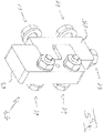
- a robot cell known from the prior art shows 2 , With reference to the other figures then an introduction station according to the invention is described using the example of a double robot cell.
- the introduction station known from the prior art according to 2 differs from the introduction station according to the invention (see, for example, the representations of 3 and 11 ) in that elements extending in the direction of transport T, namely supporting elements 53 located on the right-hand side in the transport direction and carriers 73 located on the left-hand side, which are provided here in the form of two parallel flat bars, are integral components of the supporting frame 51 designed as a welded construction, that also comprises a large number of further support elements 53 welded to one another, which extend in the transport direction T, transversely thereto and vertically.
- the mentioned elements 53 extending in the transport direction T and the flat steels 73 are also welded to vertical support elements 53 .
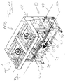
- the introduction station 113 differs from that of 2 in that the elements running in the middle and lower area in the transport direction T and welded to the other supporting elements 53 of the supporting frame are omitted and instead frame elements 55 (cf. in particular 11 ) are provided, which are not welded to the supporting elements 53 of the supporting frame 51, but are connected via mechanical bearings 57 and, in some cases, further fastening elements 67.
- these additional fastening elements 67 are also mechanical bearings, so that the term “bearing” is used below for both the bearing 57 and the fastening elements 67 in order to simplify the explanation.
- bearings which can be transferred from a released state to a fixed state, can be adjusted in the released state relative to the support elements 53 in such a way that after the bearings have been fixed and the frame elements 55 attached to the fixed bearings following the adjustment the frame members 55 are fixed to the support members 53 in a desired orientation achieved by adjusting the bearings.
- the bearings are adjusted when the frame elements 55 have not yet been attached (cf. 3 ) with the help of setting aids (e.g. templates, adapter elements, etc.) that are not shown, which in particular simulate the packaging machine to a certain extent, whereby after the frame elements 55 have been attached to the at least preset bearings (cf. 11 ) A final alignment of the frame elements 55 can be carried out if necessary by means of further aids such as spirit levels and distance gauges etc.
- setting aids e.g. templates, adapter elements, etc.
- Such an assembly concept for the frame elements 55 has proven to be simple, reliable and efficient. Alternatively, it is also possible to first connect the frame elements 55 to the bearings and to align the frame elements 55 connected to the bearings using suitable aids.
- the bearings provided according to the invention between the support elements 53 of the support frame 51 and the frame elements 55 that differ from those in the prior art 2 make it possible to use the frame elements 55 to create an inner frame that is perfectly aligned, particularly in terms of extremely high accuracy, within the support frame 51 and thus the insertion station 113, which is designed here as a double robot cell.
- This inner frame gives the support frame 51 the necessary stability, and the The inner frame itself also contributes to the overall stability of the support frame 51.
- the frame elements 55 can be designed according to the components of the parts of the packaging machine located in front of and behind the infeed station 113 and in particular with attachment features such as rows of holes 59 (cf. 12 ) are provided.
- the parts of the packaging machine can be connected to the infeed station 113 with high positioning accuracy on the input and output sides, and assemblies of the packaging machine, in particular the guide devices for the transport chains of the packaging machine, which pass through the robot cell, can be mounted on the frame elements 55 - to a certain extent "as usual".
- the guides required for such transport chains are known in principle, so that there is no need to go into more detail here.
- the insertion station 113 thus behaves like a part of the packaging machine, i.e. it does not represent a break within the packaging machine.
- the bearings 57 are mounted on both sides of vertical support elements 53 in the lower area of the insertion station 113 .
- the vertical support elements 53 are provided with widenings 69 in the transport direction T, and on both sides of these widenings 69 there are also bearings 57 as well as those mentioned in this exemplary embodiment further fastening elements 67, also designed as bearings, are attached.
- Bearings 57, 67 are also attached to the upstream and downstream sides of the vertical support elements 53, i.e. on the input side and output side on the support frame 51, which serve to connect the sections of the packaging machine (not shown) into which the infeed station 113 according to the invention is integrated.
- the structure of the bearing 57 and other fasteners 67 show the Figures 5 to 10 .
- the camp 57 according to figure 5 and 6 on the one hand and the bearing 57 according to 7 and 8th on the other hand differ from each other only in that one bearing part 65 in one case ( figure 5 and 6 ) is made in one piece and consists only of a C-shaped part that is screwed directly to a support element 53 (cf.
- This bearing part 65 is designed in several parts and has a C-shaped part 65a and a plate 65b, which are connected to one another via a projection 79 on part 65a and a matching recess 77 on plate 65b, these bearings 57 each being in the lower area of a respective vertical support member 53 are attached.
- the two bearing parts 63, 65 are each C-shaped and engage with one another.
- screw connections 61 are the two parts 63, 65 are each connected to one another and to a support element 53 of the support frame 51 or a frame element 55 (cf. 9 and 12 ).
- the two parts 63, 65 are mutually rotatable about a vertical axis D1, which is defined by the shank 61a of a screw which is inserted with a precise fit through cylindrical holes 61c in the bearing parts 63, 65 and screwed to the bearing part 63. Only this one degree of freedom (rotation about the axis D1) is realized by this screw connection 61 .
- the bearing part 65 provides two further degrees of freedom. This is via two screw connections 61 with the support element 53 ( 9 ) tied together.
- elongated holes 61b are formed in the aforementioned end plate of the widening 69, which allow a horizontal translation perpendicular to the transport direction T on the one hand.
- the shanks 61a of the screws have a diameter that is smaller than the width of the respective elongated hole 61b, this connection of the bearing part 65 to the end plate of the support element 53 allows a limited rotation about a direction parallel to the transport direction in the released state of the screw connections 61 T axis D2.
- the bearing part 65 can consequently be displaced and rotated relative to the support element 53 .
- the other bearing part 63 also permits rotation and translation, and further translation by cooperation with the frame member 55, as will be explained in more detail below.
- This bearing part 63 is not screwed to one of the support elements 53 of the support frame 51, but to a respective frame element (cf. in particular on the right in 12 ).
- the bearing element 63 is provided with two vertical elongated holes 61b, through each of which a shank 61a of a screw is passed, the diameter of which in turn is smaller than the width of the elongated hole 61b.
- the two screw connections 61 in the released state in turn allow a limited rotation about an axis D3, which runs in the horizontal direction perpendicular to the transport direction T.
- the shanks 61a of the two screws extend through elongated holes (not shown separately) formed in the respective frame element 55, which run parallel to the longitudinal extent of the frame element 55 and thus allow the frame element 55 to be moved parallel or approximately parallel to the transport direction T relative to the To move bearing part 63 and thus to the bearing part 65 and consequently to the support frame 51.
- this bearing 57 realizes six degrees of freedom for producing a respectively desired position and orientation, ie a desired alignment, of the respective frame element 55 in space.
- the other camp 57 ( 7 and 8th ) realizes the six degrees of freedom in an analogous way.
- the horizontal displacement perpendicular to the transport direction T is not provided here by slots provided in the respective support frame 53, but by slots 61b in the plate 65b (cf. also 10 ).
- This fastener 67 is a Fastening strap with two sections running at right angles to one another. One section is provided with a slot 67a through which the shanks of two screws 67d are passed in the assembled state, for which two slots 67a are also formed in the end plate of the widening 69, these slots 67a extending horizontally transversely to the transport direction T.
- the fastening element 67 can consequently be displaced both in the horizontal direction and in the vertical direction, in each case perpendicularly to the transport direction T when the screw connections are loosened.
- the fastening element 67 can be rotated to a limited extent about an axis running parallel to the transport direction T.
- the frame element 55 is fastened to the further fastening element 67 via the other section of the fastening element 67, which is provided with a cylindrical hole 67b through which the shank of a screw 67c is passed.
- the frame elements 55 are embodied as angle profiles, with a section of a respective frame element 55 being screwed to the further fastening element 67, which runs at an angle different from zero to that section of the frame element 55 which is screwed to the bearing part 63 of the other bearing 57 is.
- connection point between frame element 55 and support element 53 therefore has two bearings on widenings 69 of vertical support element 53, which enables an extremely stable connection between the respective frame element 55 and support element 53 of support frame 51 that nevertheless offers all the necessary adjustment options for alignment with all degrees of freedom .
- the relevant section of the frame element 55 is provided with a slot (not shown separately), which is Direction of the longitudinal extension of the frame member 55 runs to provide a degree of freedom for the orientation of the frame member 55 in this respect.
- a further fastening element 67 is provided, which is designed as a simple, non-angled tab.
- This fastening element 67 is screwed to a respective vertical support element 53 via two screw connections which lie vertically one above the other and for which a slot (not shown separately) running horizontally transversely to the transport direction T is provided in each case in the support element 53 .
- the handling devices each designed as a pick-and-place robot, for which the support frame 51 formed robot cell is provided and which are each indicated by a circled "R", mounted in the upper portion of the support frame 51.
- the support frame 51 is a robot double cell.
- the two robots R are arranged one after the other in the transport direction T.
- the arrangement of such robots R and their configuration are known in principle, so that they will not be discussed in any more detail.
- the robots R serve to, by means of a product feed P, which is 11 only indicated schematically by an arrow, to pick up supplied products and to insert them into pack components or to place them on pack components that are transported into the insertion station 113 by means of the transport device 27 .
- the packaging components are depressions previously produced in the upstream part of the packaging machine by means of a deep-drawing station in a lower film, with the lower film being transported along the packaging machine in the transport direction T by means of transport chains 27 spaced transversely to the transport direction T and thus also being moved through the insertion station 113 .
- These package components formed by the depressions are located within the insertion station 113 in an insertion area, with a removal area formed by the product feed P lying laterally next to the supporting frame 51 .
- the removal area is formed by the support surface of an endless belt, also referred to as an entry belt, which circulates parallel to the transport direction T in the area of the insertion station 113 and which represents the product feed P in this example.
- the removal area mentioned is as close as possible to the insertion area between the two transport chains 27 .
- the transport chains 27 are guided in guide devices, not shown here, each attached to the frame members 55 internally.
- the work paths for the robots R are therefore shorter the closer the removal area is to the outsides of the frame elements 55 on the left here in the transport direction T.
- openings 75 formed, by which not shown here and in 11 support arms 71 drawn in dashed lines are plugged in, which are also attached to the widenings 69 in the plugged-in state.
- these support arms 71 which extend horizontally perpendicularly to the transport direction T, protrude laterally, so that the product feed P can be supported on these support arms 71.
- the product feed P for example an entry belt
- the product feed P can have appropriate carriers for this purpose, by means of which the entry belt can be pushed onto the support arms 71 laterally.
- the solid support frame 51 is the basis for the robot R and for the cantilevered support arms 71 and thus the product feed P.
- This function requires a high mass and high stability, which is the support frame 51 is readily provided, but a high positional accuracy is not necessary, since any inaccuracies are comparatively small and can therefore be compensated for by the working movements of the robot R without any problems.
- the frame elements 55 of the insertion station 113 which are aligned with great accuracy thanks to the invention, contribute to fixed Bearings 57, 67 also contribute to the stability of the overall construction and - as a further function of the infeed station 113 - thanks to the precise alignment made possible by the invention, to a certain extent represent a continuation of the frame or the frame of the packaging machine through the infeed station 113. This ensures That without additional processing effort, as in accordance with the prior art 2 is necessary, a simple, uncomplicated and precise attachment of assemblies of the packaging machine, in particular the transport device comprising, for example, transport chains 27, can take place.
Landscapes
- Engineering & Computer Science (AREA)
- Mechanical Engineering (AREA)
- Auxiliary Devices For And Details Of Packaging Control (AREA)
Applications Claiming Priority (2)
| Application Number | Priority Date | Filing Date | Title |
|---|---|---|---|
| DE102021117334 | 2021-07-05 | ||
| DE102021127483.4A DE102021127483B4 (de) | 2021-07-05 | 2021-10-22 | Verpackungsmaschine |
Publications (1)
| Publication Number | Publication Date |
|---|---|
| EP4116201A1 true EP4116201A1 (fr) | 2023-01-11 |
Family
ID=82547520
Family Applications (1)
| Application Number | Title | Priority Date | Filing Date |
|---|---|---|---|
| EP22182556.5A Withdrawn EP4116201A1 (fr) | 2021-07-05 | 2022-07-01 | Machine d'emballage |
Country Status (1)
| Country | Link |
|---|---|
| EP (1) | EP4116201A1 (fr) |
Citations (12)
| Publication number | Priority date | Publication date | Assignee | Title |
|---|---|---|---|---|
| US1867226A (en) * | 1929-07-16 | 1932-07-12 | Martin James | Frame-like structure for vehicles, aircraft, and other conveyers |
| US4662149A (en) * | 1986-03-28 | 1987-05-05 | Hamilton Joel A | Table-top apparatus and method for forming sealing packages |
| DE9216764U1 (de) * | 1992-12-09 | 1993-03-11 | Horst Witte Entwicklungs- und Vertriebs KG, 2122 Bleckede | Quaderförmiges Rohr für ein System zum Aufbau von Vorrichtungen zum Aufspannen von Werkstücken |
| US6182819B1 (en) * | 1988-06-15 | 2001-02-06 | Rehm Anlagenbau Gmbh + Co. | Article carrier with adjustable support elements and a reflow soldering system provided with such an article carrier |
| DE102006006220A1 (de) * | 2006-02-09 | 2007-08-16 | Cfs Germany Gmbh | Verpackungsmaschine mit einem Rahmen |
| EP1886924A2 (fr) * | 2006-08-08 | 2008-02-13 | Multivac Sepp Haggenmüller GmbH & Co. KG | Machine d'emballage |
| US20090260958A1 (en) * | 2006-08-25 | 2009-10-22 | Tsubaki Yamakyu Chain Co., Ltd. | Track frame assembly in conveyor system |
| US7765767B2 (en) * | 2003-03-25 | 2010-08-03 | G.P.R. Scholte Holding B.V. | Multifunctional constructional modular element for machine-building of a machine frame construction for a packaging machine |
| EP2942301A1 (fr) * | 2014-05-07 | 2015-11-11 | Pester Pac Automation GmbH | Dispositif pour construction de maschines |
| US20190016494A1 (en) * | 2017-07-14 | 2019-01-17 | Multivac Sepp Haggenmüller Se & Co. Kg | Thermoform packaging machine with flexible package support |
| DE102017122703A1 (de) | 2017-08-21 | 2019-02-21 | Weber Maschinenbau Gmbh Breidenbach | Vorrichtung zum Einlegen von Produkten |
| EP3446988A1 (fr) * | 2017-08-21 | 2019-02-27 | Weber Maschinenbau GmbH Breidenbach | Dispositif de chargement de produits |
-
2022
- 2022-07-01 EP EP22182556.5A patent/EP4116201A1/fr not_active Withdrawn
Patent Citations (12)
| Publication number | Priority date | Publication date | Assignee | Title |
|---|---|---|---|---|
| US1867226A (en) * | 1929-07-16 | 1932-07-12 | Martin James | Frame-like structure for vehicles, aircraft, and other conveyers |
| US4662149A (en) * | 1986-03-28 | 1987-05-05 | Hamilton Joel A | Table-top apparatus and method for forming sealing packages |
| US6182819B1 (en) * | 1988-06-15 | 2001-02-06 | Rehm Anlagenbau Gmbh + Co. | Article carrier with adjustable support elements and a reflow soldering system provided with such an article carrier |
| DE9216764U1 (de) * | 1992-12-09 | 1993-03-11 | Horst Witte Entwicklungs- und Vertriebs KG, 2122 Bleckede | Quaderförmiges Rohr für ein System zum Aufbau von Vorrichtungen zum Aufspannen von Werkstücken |
| US7765767B2 (en) * | 2003-03-25 | 2010-08-03 | G.P.R. Scholte Holding B.V. | Multifunctional constructional modular element for machine-building of a machine frame construction for a packaging machine |
| DE102006006220A1 (de) * | 2006-02-09 | 2007-08-16 | Cfs Germany Gmbh | Verpackungsmaschine mit einem Rahmen |
| EP1886924A2 (fr) * | 2006-08-08 | 2008-02-13 | Multivac Sepp Haggenmüller GmbH & Co. KG | Machine d'emballage |
| US20090260958A1 (en) * | 2006-08-25 | 2009-10-22 | Tsubaki Yamakyu Chain Co., Ltd. | Track frame assembly in conveyor system |
| EP2942301A1 (fr) * | 2014-05-07 | 2015-11-11 | Pester Pac Automation GmbH | Dispositif pour construction de maschines |
| US20190016494A1 (en) * | 2017-07-14 | 2019-01-17 | Multivac Sepp Haggenmüller Se & Co. Kg | Thermoform packaging machine with flexible package support |
| DE102017122703A1 (de) | 2017-08-21 | 2019-02-21 | Weber Maschinenbau Gmbh Breidenbach | Vorrichtung zum Einlegen von Produkten |
| EP3446988A1 (fr) * | 2017-08-21 | 2019-02-27 | Weber Maschinenbau GmbH Breidenbach | Dispositif de chargement de produits |
Similar Documents
| Publication | Publication Date | Title |
|---|---|---|
| AT392050B (de) | Fertigungsanlage mit mehreren einzelstationen | |
| AT398923B (de) | Fertigungsanlage mit parallel- und nebenförderwegen | |
| DE69838351T2 (de) | Werkzeugmaschine | |
| EP2150373B1 (fr) | Poste d'usinage, en particulier de soudage géométrique présentant des armatures de serrage mobiles dotées d'entretoises respectives | |
| EP3150521B1 (fr) | Dispositif de groupement d'articles et procede de changement de format d'un tel dispositif | |
| DE3625787C2 (de) | Montageeinrichtung | |
| EP2008734B1 (fr) | Dispositif de transport destiné au transport de pièces à usiner sur une machine de traitement | |
| DD292407A5 (de) | Fertigungsanlage zum bearbeiten und montieren von bauteilen | |
| EP1389166B2 (fr) | Dispositif pour inserer un produit a emballer dans un materiau d'emballage | |
| EP2070647B1 (fr) | Ligne de fabrication modulaire | |
| DE3990143C1 (de) | Anlage zur Bearbeitung und oder Montage von Bauteilen | |
| EP2532456B1 (fr) | Plieuse et outil de pliage | |
| DE102021127483B4 (de) | Verpackungsmaschine | |
| DE4107709A1 (de) | Stanzpressenanordnung fuer stahltraeger | |
| EP4116201A1 (fr) | Machine d'emballage | |
| DE19581466B4 (de) | Transferpresse | |
| EP3658462B1 (fr) | Installation d'usinage pour éléments structuraux d'avions | |
| DE102015224999A1 (de) | Kabelkanalstanzvorrichtung und Verfahren zum Stanzen von Kabelkanälen | |
| DE3640675C2 (fr) | ||
| EP1152968A2 (fr) | Procede pour decouper des feuilles de tole en bandes de tole, et dispositif de coupe permettant la mise en oeuvre de ce procede | |
| DE102017122703A1 (de) | Vorrichtung zum Einlegen von Produkten | |
| EP3395696B1 (fr) | Emballage des produits alimentaires | |
| DE102020126787A1 (de) | Verpackungsmaschine sowie Verfahren zur Verpackung einer Behältnisgruppe aus mehreren Behältnissen | |
| EP3446988A1 (fr) | Dispositif de chargement de produits | |
| AT402619B (de) | Fertigungsanlage mit parallel- und fertigungsanlage mit parallel- und nebenförderwegen nebenförderwegen |
Legal Events
| Date | Code | Title | Description |
|---|---|---|---|
| PUAI | Public reference made under article 153(3) epc to a published international application that has entered the european phase |
Free format text: ORIGINAL CODE: 0009012 |
|
| STAA | Information on the status of an ep patent application or granted ep patent |
Free format text: STATUS: THE APPLICATION HAS BEEN PUBLISHED |
|
| AK | Designated contracting states |
Kind code of ref document: A1 Designated state(s): AL AT BE BG CH CY CZ DE DK EE ES FI FR GB GR HR HU IE IS IT LI LT LU LV MC MK MT NL NO PL PT RO RS SE SI SK SM TR |
|
| STAA | Information on the status of an ep patent application or granted ep patent |
Free format text: STATUS: REQUEST FOR EXAMINATION WAS MADE |
|
| 17P | Request for examination filed |
Effective date: 20230330 |
|
| RBV | Designated contracting states (corrected) |
Designated state(s): AL AT BE BG CH CY CZ DE DK EE ES FI FR GB GR HR HU IE IS IT LI LT LU LV MC MK MT NL NO PL PT RO RS SE SI SK SM TR |
|
| RIN1 | Information on inventor provided before grant (corrected) |
Inventor name: DORNOEFER, NICKLAS Inventor name: LENZ, DANIEL |
|
| P01 | Opt-out of the competence of the unified patent court (upc) registered |
Effective date: 20230522 |
|
| RAP3 | Party data changed (applicant data changed or rights of an application transferred) |
Owner name: WEBER FOOD TECHNOLOGY GMBH |
|
| STAA | Information on the status of an ep patent application or granted ep patent |
Free format text: STATUS: THE APPLICATION HAS BEEN WITHDRAWN |
|
| 18W | Application withdrawn |
Effective date: 20240304 |