EP4112935B1 - Pumpe und luftzufuhrvorrichtung - Google Patents
Pumpe und luftzufuhrvorrichtung Download PDFInfo
- Publication number
- EP4112935B1 EP4112935B1 EP21780810.4A EP21780810A EP4112935B1 EP 4112935 B1 EP4112935 B1 EP 4112935B1 EP 21780810 A EP21780810 A EP 21780810A EP 4112935 B1 EP4112935 B1 EP 4112935B1
- Authority
- EP
- European Patent Office
- Prior art keywords
- pump
- movable body
- magnet
- core portion
- movable
- Prior art date
- Legal status (The legal status is an assumption and is not a legal conclusion. Google has not performed a legal analysis and makes no representation as to the accuracy of the status listed.)
- Active
Links
Images












Classifications
-
- F—MECHANICAL ENGINEERING; LIGHTING; HEATING; WEAPONS; BLASTING
- F04—POSITIVE - DISPLACEMENT MACHINES FOR LIQUIDS; PUMPS FOR LIQUIDS OR ELASTIC FLUIDS
- F04B—POSITIVE-DISPLACEMENT MACHINES FOR LIQUIDS; PUMPS
- F04B45/00—Pumps or pumping installations having flexible working members and specially adapted for elastic fluids
- F04B45/04—Pumps or pumping installations having flexible working members and specially adapted for elastic fluids having plate-like flexible members, e.g. diaphragms
- F04B45/047—Pumps having electric drive
-
- B—PERFORMING OPERATIONS; TRANSPORTING
- B06—GENERATING OR TRANSMITTING MECHANICAL VIBRATIONS IN GENERAL
- B06B—METHODS OR APPARATUS FOR GENERATING OR TRANSMITTING MECHANICAL VIBRATIONS OF INFRASONIC, SONIC, OR ULTRASONIC FREQUENCY, e.g. FOR PERFORMING MECHANICAL WORK IN GENERAL
- B06B1/00—Methods or apparatus for generating mechanical vibrations of infrasonic, sonic, or ultrasonic frequency
- B06B1/02—Methods or apparatus for generating mechanical vibrations of infrasonic, sonic, or ultrasonic frequency making use of electrical energy
- B06B1/04—Methods or apparatus for generating mechanical vibrations of infrasonic, sonic, or ultrasonic frequency making use of electrical energy operating with electromagnetism
- B06B1/045—Methods or apparatus for generating mechanical vibrations of infrasonic, sonic, or ultrasonic frequency making use of electrical energy operating with electromagnetism using vibrating magnet, armature or coil system
-
- F—MECHANICAL ENGINEERING; LIGHTING; HEATING; WEAPONS; BLASTING
- F04—POSITIVE - DISPLACEMENT MACHINES FOR LIQUIDS; PUMPS FOR LIQUIDS OR ELASTIC FLUIDS
- F04B—POSITIVE-DISPLACEMENT MACHINES FOR LIQUIDS; PUMPS
- F04B45/00—Pumps or pumping installations having flexible working members and specially adapted for elastic fluids
- F04B45/04—Pumps or pumping installations having flexible working members and specially adapted for elastic fluids having plate-like flexible members, e.g. diaphragms
- F04B45/043—Pumps or pumping installations having flexible working members and specially adapted for elastic fluids having plate-like flexible members, e.g. diaphragms two or more plate-like pumping flexible members in parallel
-
- H—ELECTRICITY
- H02—GENERATION; CONVERSION OR DISTRIBUTION OF ELECTRIC POWER
- H02K—DYNAMO-ELECTRIC MACHINES
- H02K33/00—Motors with reciprocating, oscillating or vibrating magnet, armature or coil system
- H02K33/16—Motors with reciprocating, oscillating or vibrating magnet, armature or coil system with polarised armatures moving in alternate directions by reversal or energisation of a single coil system
-
- B—PERFORMING OPERATIONS; TRANSPORTING
- B06—GENERATING OR TRANSMITTING MECHANICAL VIBRATIONS IN GENERAL
- B06B—METHODS OR APPARATUS FOR GENERATING OR TRANSMITTING MECHANICAL VIBRATIONS OF INFRASONIC, SONIC, OR ULTRASONIC FREQUENCY, e.g. FOR PERFORMING MECHANICAL WORK IN GENERAL
- B06B2201/00—Indexing scheme associated with B06B1/0207 for details covered by B06B1/0207 but not provided for in any of its subgroups
- B06B2201/50—Application to a particular transducer type
- B06B2201/52—Electrodynamic transducer
- B06B2201/53—Electrodynamic transducer with vibrating magnet or coil
Definitions
- the present invention relates to a pump and an air supply device using a vibration actuator.
- a plurality of diaphragms forming a pump chamber are provided in a case, a suction valve is provided in the pump chamber and a cylindrical discharge valve body is formed at a center portion of the pump chamber.
- the plurality of diaphragms are connected to a swinging body which can be swung by rotation of an eccentric rotation shaft and thus the diaphragms can move up and down when the swinging body swings.
- the eccentric rotation shaft is eccentrically fixed to a disk portion fixed to a rotation shaft of a DC motor disposed below the eccentric rotation shaft.
- This pump uses the eccentric rotation shaft and the swinging body to convert normal rotation of the DC motor around the rotation shaft thereof into precession movement for moving the diaphragms up and down.
- the pump of the patent document 2 is a reciprocating motor having a cylindrical shape.
- Each of a fixed portion and a movable portion of this reciprocating motor has a magnet and the pump device is driven by utilizing a resonance phenomenon to achieve air suction and air discharge.
- a diaphragm is reciprocated by the piezoelectric element to repeat air suction and air discharge through valves for switching between the air suction and the air discharge.
- Document WO 2017/140180 A1 discloses an electromagnetically driven pump having a reciprocally rotating vibration actuator according to the preamble of claim 1, where a movable wall is linearly pressed during the rotating motion of the vibration actuator. Linear pressing of the movable wall is provided by a diaphragm push rod, which is pushed in alternating directions by the vibration actuator.
- the present invention has been made in view of the above-described conventional problems. Accordingly, it is an object of the present invention to provide a high-performance pump whose thickness can be reduced and which can secure a high discharge pressure and a large transfer flow rate and an air supply device including the high-performance pump.
- Fig. 1 is an external perspective view of a pump according to a first embodiment of the present invention.
- Fig. 2 is a planar view showing a main part configuration of the pump according to the first embodiment of the present invention.
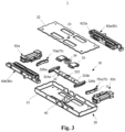
- Fig. 3 is an exploded perspective view of the pump according to the first embodiment of the present invention.
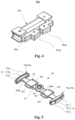
- Fig. 4 is a perspective view of a coil core portion in the pump according to the first embodiment of the present invention.
- Fig. 5 is a perspective view of a movable body in the pump according to the first embodiment of the present invention.
- Fig. 6 is a horizontal cross-sectional view showing an internal configuration of the pump according to the first embodiment of the present invention.
- Fig. 7 is an exploded perspective view of a pump unit in the pump according to the first embodiment of the present invention.
- a vibration direction of a movable body which performs reciprocating rotation in a vibration actuator of the pump is defined as a direction shown in Fig. 2 .
- the description will be given with assuming that two directions perpendicular to this direction are respectively defined as a horizontal direction (a left-right direction) and a height direction (a vertical direction, also referred to as a thickness direction).
- each expression indicating the directions such as "left-right (lateral)” and “height (vertical)” used to explain a configuration and operation of each part of the pump is not an absolute expression but a relative expression. Although these expressions are appropriate when each part of the pump take a posture shown in each figure, these expressions should be appropriately interpreted depending on the posture of each part of the pump if the posture is changed.
- a pump 1 shown in Fig. 1 and Fig. 2 is a pump for discharging air by utilizing an action of a vibration actuator 10 which can be electromagnetically driven.
- a target object to be discharged and suctioned by the pump is not limited to air as long as it is fluid.
- the target object to be discharged and suctioned by the pump is gas.
- the pump 1 of the present embodiment includes a vibration actuator 10 in which a movable body 30 is provided so as to freely perform reciprocating rotation with respect to a fixed body 20 through a shaft portion 40 and pump units 80 (80a, 80b) for discharging and suctioning air due to driving of the vibration actuator 10.
- the movable body 30 is provided in a case 21 of the fixed body 20 through the shaft portion 40 so that the movable body 30 can freely perform the reciprocating rotation.
- the movable body 30 can reciprocate (that is, vibrate) with respect to the fixed body 20 along an axial direction of the shaft portion 40.
- the pump 1 can discharge and suction the air through a discharge portion 86 by utilizing vibration of the movable body 30.
- the movable body 30 is provided in the case 21 having a rectangular shape in a planar view thereof so that the movable body 30 can freely perform the reciprocating rotation around the shaft portion 40 disposed at a center of the case 21.
- the magnets 70a, 70b are respectively provided on the inner surface sides of both wall portions of the case 21 separated from each other in a longitudinal direction of the movable body 30.
- a coil core portion 62a including the coil 50a and the core portion 60a is provided on an inner surface of the wall portion of the case 21 of the fixed body 20 which faces the magnet 70a.
- Another coil core portion 62b including the coil 50b and the core portion 60b is provided on an inner surface of the wall portion of the case 21 of the fixed body 20 which faces the magnet 70b.
- Each of the magnets 70a, 70b is preferably a permanent magnet, for example. Further, it is preferable that each of magnets 70A, 70B, 70C described later is also a permanent magnet.
- the vibration actuator 10 includes the fixed body 20, the shaft portion 40 and the movable body 30 supported by the shaft portion 40 so that the movable body 30 can freely perform the reciprocating rotation with respect to the fixed body 20.
- the magnets 70 (70a, 70b) are provided on one of the fixed body 20 and the movable body 30.
- the coil core portions 62 (62a, 62b) which are disposed so that magnetized surfaces of cores of each coil core portion 62a, 62b respectively face the magnets 70a, 70b are provided on the other one of the fixed body 20 and the movable body 30.
- the magnets 70a, 70b are provided on the movable body 30 and the coil core portions 62 (62a, 62b) are provided on the fixed body 20.
- the movable body 30 includes the magnets 70a, 70b and the fixed body 20 includes the coil core portions 62a, 62b.
- the fixed body 20 includes the case 21, a cover 22 and the coil core portions 62a, 62b. Further, the pump units 80 (80a, 80b) are provided on the fixed body 20.
- the coil core portions 62a, 62b are respectively disposed on the inner surfaces of both wall portions of the case 21 separated from each other in a longitudinal direction of the case 21 so as to respectively face the magnets 70a, 70b on the movable body 30.
- the shaft portion 40 is provided on a center of a bottom surface of the case 21 in the horizontal direction and the depth direction of the case 21 so as to extend in the height direction of the case 21.
- the shaft portion 40 is fitted and fixed to a shaft hole 23 of the cover 22 in a state that the shaft portion 40 is passed through a bearing portion 34 of the movable body 30 by press-fitting or bonding after the shaft portion 40 is inserted into the shaft hole 23. With this configuration, the shaft portion 40 is supported in a state that the shaft portion 40 is passed through the bearing portion 34 of the movable body 30 and bridged between the bottom surface of the case 21 and the cover 22.
- the coil core portions 62a, 62b are respectively disposed on the inner surfaces of both wall portions of the case 21 separated from each other in the longitudinal direction of the case 21 so as to face each other. Further, the coil core portions 62a, 62b are disposed so as to sandwich the movable body 30 in the longitudinal direction of the case 21.
- the coil core portions 62a, 62b are configured so as to have the same configuration and respectively provided at positions symmetrical around an axis of the shaft portion 40 in the planar view.
- the core portions 60a, 60b are magnetic bodies which can be magnetized when an electrical current flows in the coils 50a, 50b.
- the core portions 60a, 60b may be made of electromagnetic stainless material, sintered material, metal injection mold (MIM) material, a laminated steel sheet, an electrogalvanized steel sheet (SECC) or the like.
- MIM metal injection mold
- SECC electrogalvanized steel sheet
- each of the core portions 60a, 60b is constituted of laminated cores made of the laminated steel sheet.
- the core portions 60a, 60b respectively have cores 601a, 601b around which the coils 50a, 50b are respectively wound and magnetic poles (hereinafter, for convenience, referred to as "core magnetic poles") 602a, 603a, 602b, 603b formed continuously with both end portions of the cores 601a, 601b.
- core magnetic poles hereinafter, for convenience, referred to as "core magnetic poles”
- each of the core magnetic poles 602a, 603a, 602b, 603b has a magnetic pole surface curved so as to have an arc planar shape corresponding to a shape of a magnetized surface of each of the magnets 70a, 70b which can perform reciprocating rotation.
- the core magnetic poles 602a, 603a of the core portion 60a face the magnet 70a and the core magnetic poles 602b, 603b of the core portion 60b face the magnet 70b.
- the core magnetic poles 602a, 603a, 602b, 603b are aligned in a rotation direction of the reciprocating rotation of the movable body 30.
- the core magnetic poles 602a, 603a, 602b, 603b are preferably disposed on a circumference of a circle around the shaft portion 40. This circumference is a circumferential track along a movement track of the magnets 70a, 70b.
- the core magnetic poles 602a, 603a, 602b, 603b of the core portions 60a, 60b around which the coils 50a, 50b are respectively wound are disposed so as to face a magnetization direction of the magnets 70a, 70b.
- the coils 50a, 50b in the core portions 60a, 60b are connected to, for example, a power supply unit (not shown).
- a power supply unit not shown.
- the core magnetic poles 602a, 603a, 602b, 603b are excited.
- the core magnetic poles 602a, 603a, 602b, 603b are excited so as to have a polarity differing from a polarity of the core magnetic poles 603a, 603b in each of the core portions 60a, 60b.
- the bearing portion 34 is fixed to the movable body main portion 32 and the shaft portion 40 is passed through the bearing portion 34.
- the pair of magnets 70a, 70b are fixed to the movable body main portion 32 so as to sandwich the shaft portion 40 passed through the bearing portion 34.
- the movable body main portion 32 may or may not be a magnetic body (a ferromagnetic body).
- the movable body main portion 32 is a yoke and serves as a weight of the movable body 30.
- the movable body main portion 32 is constituted by laminating yoke iron cores, for example.
- the constituent material of the movable body main portion 32 is not limited to metal material. Resin material or the like may be used as the constituent material of the movable body main portion 32.
- the movable body main portion 32 has a center opening portion 322 formed at a center portion of the movable body main portion 32 and to which the bearing portion 34 is fixed and arm portions 324a, 324b respectively extending in opposite directions from the center portion.
- Each of the arm portions 324a, 324b has an elongated flat plate-like shape and end portions of the arm portions 324a, 324b are formed so as to protrude in a direction perpendicular to the extending direction.
- magnet fixing portions 326a, 326b are respectively formed on tip end surfaces of the arm portions 324a, 324b.
- a tip end surface of each of the magnet fixing portions 326a, 326b is formed to be curved in an arc shape.
- the magnets 70a, 70b are respectively fixed to the tip end surfaces of the magnet fixing portions 326a, 326b.
- the pressing portions 35 are respectively provided on the arm portions 324a, 324b.
- the magnetic poles 721, 722, 723 of each of the magnets 70a, 70b are disposed so as to be adjacent to each other in the depth direction perpendicular to an axis line of the shaft portion 40 through the shaft portion 40, that is, in the rotation direction.
- the pressing portion 35 is connected to the movable wall 822 of the pump unit 80 through the pusher 351.
- the pusher 351 is inserted into an insertion portion 822a of the movable wall 822 serving as a diaphragm when the movable body 30 performs the rotational movement to push and displace the movable wall 822 in the rotation direction.
- the pressing portion 35 moves toward the side of the movable wall 822 to press the movable wall 822 when the movable body 30 rotates.
- the movable body main portion 32 When the electrical current is not supplied to the coils 50a, 50b, the movable body main portion 32 is biased so as to be positioned at a center of the case 21 (the fixed body 20) in longitudinal direction by functions of magnetic springs provided by the core portions 60a, 60b and the magnets 70a, 70b.
- the movable wall 822 is formed of, for example, elastically deformable material and is provided so as to close the chamber forming portion 824.
- the movable wall 822 is a diaphragm.
- the movable wall 822 has the insertion portion 822a into which the pusher 351 of the pressing portion 35 is inserted and is connected to the pressing portion 35 through the insertion portion 822a.
- the movable wall 822 is displaced when the movable wall 822 is pressed by the pressing portion 35 which moves in accordance with the rotation of the movable body 30.
- the movable wall 822 is inserted into the chamber forming portion 824 by one-side rotation movement (swing to one side of the rotation direction) of the reciprocating rotation of the movable body 30 to press the inside of the chamber forming portion 824 and reduce the volume in the sealed chamber 82 for discharging the air.
- the movable wall 822 increases the volume in the sealed chamber 82 to suction the air.
- the sealed chamber 82 is a sealed space to which the suction portion 83 and the discharge portion 86 are connected and whose volume can be changed by the displacement of the movable wall 822.
- the discharge portion 86 has a discharge port communicated with the outside and discharges the air from the pump 1 to the outside through the discharge port.
- the discharge port may be an opening communicated with the discharge portion 86 connected to a bottom surface of the sealed chamber 82.
- the movable wall 822 when the movable wall 822 is pressed by the pressing portion 35, the movable wall 822 is elastically deformed toward the inside of the sealed chamber 82 to press the air in the sealed chamber 82.
- the pressed air in the sealed chamber 82 is discharged to the outside through the discharge portion 86.
- the movable wall 822 moves so as to return to an initial position, that is, when the pressed state by the pressing portion 35 is released and the volume in the sealed chamber 82 increases from the pressed state, the air is suctioned from the outside into the sealed chamber 82 through the suction portion 83.
- the suction portion 83 has a suction port and can suction the air into the sealed chamber 82 through the suction port.
- the suction port may be an opening communicated with the suction portion 83 in the chamber forming portion 824.
- Each of the pump units 80 is disposed in the case 21 along the extending direction of the movable body 30, that is, along side wall portions of the case 21 extending in the longitudinal direction of the case 21. Further, the pump units 80 (80a, 80b) are disposed so as to sandwich the movable body main portion 32 of the movable body 30 in the depth direction of the case 21.
- the base 801 has an opening.
- the insertion portion 822a of the diaphragm portion 802 is passed through the opening of the base 801 from a rear surface side of the base 801 so as to protrude toward a front surface side of the base 801.
- the base 801 and the flow path forming portion 807 constitute a housing of the pump unit 80 having a strip shape.
- the diaphragm portion 802 is formed from elastic material such as rubber.
- the diaphragm portion 802 has the insertion portion 822a and the movable wall 822.
- the chamber forming portion 824 of the cylinder portion 803 is disposed on the rear surface side of the movable wall 822 which has flexibility and can be elastically deformed.
- the diaphragm portion 802 and the cylinder portion 803 are attached to each other so that the movable wall 822 of the diaphragm portion 802 and the chamber forming portion 824 of the cylinder portion 803 define the sealed chamber 82 which is a sealed space.
- the cylinder portion 803 has the chamber forming portion 824 and two communication holes formed in a surface facing the movable wall 822 in the sealed chamber 82 so as to be respectively communicated with the discharge portion 86 and the suction portion 83.
- the two communication holes are respectively connected to the discharge flow path portion 88 and the suction portion 83 of the flow path forming portion 807 and the valve cover portion 805 through the valves 84 of the valve portion 804 which are attached from the rear surface side of the cylinder portion 803 so as to overlap with the two communication holes.
- the valve portion 804 is attached to the valve cover portion 805.
- the valve 84 connected to the discharge portion 86 is configured to communicate with the discharge portion 86 of the flow path forming portion 807 when the volume in the sealed chamber 82 decreases.
- the valve 84 connected to the discharge portion 86 is configured to be closed when the volume in the sealed chamber 82 increases.
- the valve portion 804 is attached to the valve cover portion 805.
- the valve 84 connected to the suction portion 83 is configured to be closed when the volume in the sealed chamber 82 decreases.
- the valve 84 connected to the suction portion 83 is configured to communicate with the suction portion 83 of the flow path forming portion 807 when the volume in the sealed chamber 82 increases.
- each of the pump units 80 has the pair of sealed chambers 82 each constituted of the chamber forming portion 824 and the movable wall 822.
- Each of the pump units 80 (80a, 80b) is disposed so that its own pair of sealed chambers 82 respectively face side surfaces of the arm portions 324a, 324b extending in directions opposite to each other through the shaft portion 40.
- the pump units 80 (80a, 80b) are disposed so as to face each other at positions where the arm portions 324a, 324b are sandwiched between the pairs of sealed chambers 82 of the pump units 80 (80a, 80b) in the direction of the reciprocation and rotation movement of the arm portions 324a, 324b.
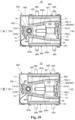
- FIG. 9A and Fig. 9B is a view showing an air discharge operation or an air suction operation of the pump according to the first embodiment of the present disclosure.
- the movable wall 822 elastically returns in accordance with the movement of the pressing portion 35 and the volume in the sealed chamber 82 is returned, that is, increased as shown in Fig. 9B .
- the valve 84 connected to the discharge portion 86 is tightened to close the discharge path and the valve 84 connected to the suction portion 83 is opened.
- the air is suctioned into the sealed chamber 82 through the suction portion 83 (indicated by white arrows in the Fig. 9B ).
- the core portions 60a, 60b which are magnetic members are disposed in the case 21 so as to respectively face the magnets 70a, 70b with being apart from the magnets 70a, 70b in the longitudinal direction as shown in Fig. 2 and Fig. 6 .
- the magnets 70a, 70b are respectively disposed at both ends of the movable body 30 so as to face each other through the shaft portion 40.
- the core portions 60a, 60b are respectively disposed on inner surfaces of both wall portions of the case 21 in the longitudinal direction so as to face each other with being apart from each other in the longitudinal direction.
- Magnetic attraction force is generated between the core portion 60a and the magnet 70a and between the core portion 60b and the magnet 70b. Since these two kinds of magnetic attraction force generated in the longitudinal direction (the extending direction of the arm portion 324a, 324b) are generated in opposite directions on one straight line through the shaft portion 40, these two kinds of magnetic attraction force cancel each other.
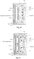
- Fig. 10 is a view showing a magnetic spring of the pump unit according to the first embodiment of the present invention.
- a magnetic circuit provided by the coil core portion 62a and the magnet 70a and a magnetic circuit provided by the coil core portion 62b and the magnet 70b are configured to be point-symmetrically around the shaft portion 40.
- the magnetic circuit provided by the coil core portion 62a and the magnet 70a will be described in Fig. 10 and description for the magnetic circuit provided by the coil core portion 62b and the magnet 70b will be omitted.
- the magnet 70a has a configuration in which the magnetic poles 721, 722, 723 on the magnetic pole surface 72 facing the core portion 60a are respectively magnetized as N pole, S pole and N pole.
- Each of the magnetic poles 721 to 723 on the magnetic pole surface 72 of the magnet 70a respectively attracts the core magnetic poles 602a, 603a close to each of the magnetic poles 721 to 723.
- the center magnetic pole 722 of the magnet 70a attracts both of the core magnetic poles 602a, 603a.
- the magnetic pole 721 of the magnet 70a attracts the core magnetic pole 602a.
- the magnetic pole 723 of the magnet 70a attracts the core magnetic pole 603a.
- the center magnetic pole 722 of the magnet 70a is located at the center of the coil core portion 62a, that is, at a position between the core magnetic poles 602a, 603a.
- the core magnetic poles 602a, 603a of the core portion 60a are excited with different polarities.
- thrust force is generated with respect to the movable body 30 in accordance with the relationship with the magnet 70a disposed so as to face the coil core portion 62a.
- the same discussion can be applied to the magnetic circuit provided by the coil core portion 62b and the magnet 70b.
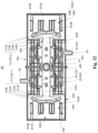
- Fig. 11 is a view showing the magnetic circuit configuration of the pump according to the first embodiment of the present invention.
- Fig. 10 similarly to the description with reference to Fig. 10 , only the magnetic circuit provided by the coil core portion 62a and the magnet 70a will be described in the description for the example of the operation of the pump 1 with reference to Fig. 11 and description for the magnetic circuit provided by the coil core portion 62b and the magnet 70b will be omitted.
- the magnet 70a has three different polarities on the magnetic pole surface 72 so that the three different polarities are alternately arranged in the rotation direction.
- the central magnetic pole 722 is the S pole and each of the magnetic poles 721, 723 sandwiching the center magnetic pole 722 is the N pole on the magnetic pole surface 72 facing the core portion 60a.
- the core magnetic pole 602a of the core portion 60a is magnetized with the S pole and the core magnetic pole 603a of the core portion 60a is magnetized with the N pole as shown in Fig. 11 .
- the driving principle of the vibration actuator 10 of the present embodiment is realized by all of the vibration actuators used in the following embodiments.
- an alternating current having a frequency substantially equal to the resonant frequency fr of the movable body 30 is supplied to the coils 50a, 50b to excite the core portions 60a, 60b (more specifically, the core magnetic poles 602a, 603a, 602b, 603b) with the coils 50a, 50b.
- the core portions 60a, 60b more specifically, the core magnetic poles 602a, 603a, 602b, 603b
- the movable body 30 in the vibration actuator 10 of the present embodiment is in a state that it is supported by a spring mass system structure constituted of the magnetic springs provided by the magnets 70a, 70b and the coil core portions 62a, 62b respectively having the coils 50a, 50b and the core portions 60a, 60b.
- a spring mass system structure constituted of the magnetic springs provided by the magnets 70a, 70b and the coil core portions 62a, 62b respectively having the coils 50a, 50b and the core portions 60a, 60b.
- the reference position of the movable body that is, the rest position of the movable body changes due to pressing force (loads) generated with respect to the movable body when the pressure of the pump unit increases. If the movable body starts the reciprocating rotation from a position shifted from the reference position, the movable body may move within a movement range differing from the movement range when the movable body starts the reciprocating rotation from the reference position. In the pump unit of the conventional pump, this movement may shift the displacement position of the movable wall caused by the pressing portion and set as a distance from the reference position.
- the air in the sealed chamber 82 cannot be sufficiently compressed and the desired discharge pressure and the desired flow rate for the air cannot be ensured.
- FIG. 12A and Fig. 12B is a schematic diagram which is referred to explain operation of the pump unit in the pump according to the first embodiment of the present invention.
- FIG. 13A and Fig. 13B is a schematic diagram which is referred to explain the operation of the pump unit if the number of pump units is one.
- the sealed chambers 82 (which respectively correspond to the "air chambers" in Fig. 12 and Fig. 13 ) in the pump units 80 (80a, 80b) are disposed so as to face each other in the direction perpendicular to the extending direction of the movable body 30 and sandwich the movable body 30 in the reciprocating rotational movement direction of the movable body 30, that is, from both sides of the vibration direction of the arm portions 324a, 324b located at the reference position.
- the four sealed chambers 82 are disposed to sandwich the shaft portion 40 and sandwich the arm portions 324a, 324b of the movable body 30 in the depth direction.
- the movable body 30 has the arm portions 324a, 324b which are respectively provided so as to extend toward the direction perpendicular to the axial direction of the shaft portion 40 from a position where the movable body 30 is axially supported by the shaft portion 40 so as to be freely reciprocated and rotated.
- the other one of the coil core portions 62a, 62b and the magnets 70a, 70b are respectively provided at the tip end portions (the magnet fixing portions 326a, 326b) of the arm portions 324a, 324b.
- the sealed chambers 82 are provided in pairs sandwiching the arm portions 324a, 324b of the movable body 30.
- the pair of sealed chambers 82 (shown as the "air chambers" in Fig. 12 ) are disposed so as to face each other at positions for sandwiching the arm portions 324a, 324b in the reciprocating rotation direction of the arm portions 324a, 324b (the depth direction of the case 21).
- Each of the pressing portions 35 has the pair of pushers 351, 351 respectively corresponding to the pair of movable walls 822.
- the movable walls 822 of the pair of the sealed chambers 82, 82 are respectively pressed by the corresponding pushers 351 when the arm portions 324a, 324b perform the reciprocating rotation.
- the pressing portions 35 of the movable body 30 are respectively connected to the movable walls 822 defining the pair of the sealed chambers 82 (the "air chambers") located on both sides of the reciprocating rotation direction of the reciprocating rotational movement of the movable body 30 in the present embodiment.
- the movable walls 822 are displaced by loads generated when pressure in the sealed chambers 82 increases to press the movable body 30 through the pressing portions 35.
- the movable body 30 has the pair of arm portions 324a, 324b which are axially supported by the shaft portion 40 at the center portion of the case 21 so as to be freely reciprocated and rotated and which oppositely extend from the center portion of the case 21 in the direction perpendicular to the axial direction of the shaft portion 40 in the present embodiment.
- the other one (the magnets 70a, 70b in the present embodiment) of the coil core portions 62a, 62b and the magnets 70a, 70b is respectively provided on the tip end portions of the arm portions 324a, 324b, that is, the magnet fixing portions 326a, 326b.
- the one (the coil core portions 62a, 62b in the present embodiment) of the coil core portions 62a, 62b and the magnets 70a, 70b is respectively provided on the fixed body 20 so as to face the other one (the magnets 70a, 70b in the present embodiment) of the coil core portions 62a, 62b and the magnets 70a, 70b.
- Each of the pump units 80 (80a, 80b) contains the pair of sealed chambers 82.
- the pair of sealed chambers 82 of each pump unit 80 (80a, 80b) are disposed so as to be in parallel with each other along the extending direction of the pair of arm portions 324a, 324b.
- each of the pressing portions 35 has the pair of pushers 351 respectively corresponding to the pair of movable walls 822 of the sealed chamber 82 of the pump unit 80a and the movable wall 822 of the sealed chamber 82 of the pump unit 80b.
- Each of the movable walls 822 of the sealed chambers 82 is pressed by the pressing portion 35 when the arm portions 324a, 324b performs the reciprocating rotation.
- each of the pump units 80 (80a, 80b) of the present embodiment contains the plurality of sealed chambers 82 aligned in the longitudinal direction thereof. Further, the discharge flow paths and the discharge ports of the sealed chambers 82 are connected in parallel. As a result, when the movable body 30, that is, the arm portions 324a, 324b perform the reciprocating rotation around the shaft portion 40, the pushers 351 of the pressing portions 35 alternately press the movable walls 822 of the sealed chambers 82 disposed in parallel in the longitudinal direction. With this configuration, it is possible to provide the pump 1 with the high flow rate.
- the pump 1 of the present embodiment has the configuration in which the magnets 70a, 70b required to operate the magnetic springs are provided on one of the movable body 30 and the fixed body 20, it is possible to reduce the number of parts of the pump 1 as compared with the configuration in which the magnets 70a, 70b are provided on both of the movable body 30 and the fixed body 20.
- the coil core portion 62a corresponding to the magnet 70a located on the one side of the movable body 30 constitutes the magnetic circuit with one coil. Thus, it is possible to reduce the cost of the pump 1.
- Fig. 14 is an external perspective view of a pump according to a second embodiment of the present invention.
- Fig. 15 is a planar view the pump according to the second embodiment of the present invention in a state that a cover of the pump is omitted for the explanation.
- Fig. 16 is an exploded perspective view of the pump according to the second embodiment of the present invention.
- Fig. 17 is a perspective view of a coil core portion in the pump according to the second embodiment of the present invention.
- Fig. 18 is a perspective view of a movable body in the pump according to the second embodiment of the present invention.
- Fig. 19 is a horizontal cross-sectional view showing an internal configuration of the pump according to the second embodiment of the present invention.
- a pump 1A has the same basic configuration as the basic configuration of the pump 1 corresponding to the first embodiment shown in Fig. 1 except that the configuration of the magnetic circuit is modified.
- the same components are denoted by the same reference numbers and description for the same components will be omitted in the following description.
- the pump 1A of the present embodiment has the same basic configuration as the basic configuration of the pump 1 of the first embodiment except the number of poles of a magnet 70A and the number of poles of a coil core portion 62A are different from corresponding ones of the pump 1.
- the pump 1A is configured so that a movable body 30A is provided in a case 21A of a fixed body 20A which has a rectangular planar shape so as to freely perform reciprocating rotation around a shaft portion 40A disposed at a center of the case 21A.
- Four-pole magnets 70A-1, 70A-2 are respectively provided at both ends of the movable body 30A which are disposed so as to be separated from each other in a longitudinal direction of the movable body 30A perpendicular to an axial direction of the shaft portion 40A.
- coil core portions 62A-1, 62A-2 each having three core magnetic poles are provided in the case 21 and at positions respectively facing the magnets 70A-1, 70A-2 through an air gap and aligned along wall portions separated from each other in a longitudinal direction of the case 21A.
- the pump units 80a, 80b are provided along the extending direction of the movable body 30A in the case 21A so as to sandwich the movable body 30A in the depth direction of the case 21A.
- the movable walls 822 of the pump units 80a, 80b are respectively connected to the pressing portions 35 of the movable body 30A which is configured in the same manner as the pressing portions 35 of the pump 1.
- coil core portion 62A-1 and the coil core portion 62A-2 have the same configuration, only the configuration of the coil core portion 62A-1 will be described and the description for the coil core portion 62A-2 will be omitted.
- the coil core portion 62A-1 has a coil 50A and the core portion 60A having an E-shape.
- the coil 50A is wound around a center protrusion of the core portion 60A through a bobbin 65A.
- the center protrusion of the core portion 60A serves as a core magnetic pole 601A.
- a tip end portion of the center protrusion of the core portion 60A serves as the core magnetic pole 601A and core magnetic poles 602A, 603A connected to a base end portion of the core magnetic pole 601A are magnetized with a magnetic pole different from a magnetic pole of the core magnetic pole 601A.
- a peripheral surface of the tip end portion of the core magnetic pole 601A is covered by a flange of the bobbin 65A so that the core magnetic pole 601A partially protrudes from the bobbin 65A.
- the core magnetic poles 601A, 602A, 603A of the coil core portion 62A-1 are disposed in an arc track so as to face the magnet 70A-1.
- the coil core portion 62A-2 which is configured similarly to the coil core portion 62A-1 is disposed with being separated from the coil core portion 62A-1 in the longitudinal direction of the case 21 so that core magnetic poles 601A, 602A, 603A of the coil core portion 62A-2 face the magnet 70A-2.
- the magnets 70A-1, 70A-2 are respectively fixed to the magnet fixing portions 326a, 326b on both end portions of the movable body main portion 32 in which the bearing portion 34 is provided at the center portion of the movable body main portion 32.
- Magnetic pole surfaces 72 of each of the magnets 70A-1, 70A-2 are disposed so as to have an outwardly protruding arc track and be separated from each other in the longitudinal direction perpendicular to the axis of the shaft portion 40A.
- the core magnetic poles 601A to 603A of the core portions 60A of the core portions 62A-1, 62A-2 respectively face the magnetic pole surfaces 72 of the magnets 70A-1, 70A-2.
- the magnetic pole 721A of the magnet 70A is the N pole
- the magnetic attraction force is generated between the magnetic pole 721A and the core magnetic pole 602A which is the S pole.
- the magnetic pole 724A of the magnet 70A which is the S pole repels the core magnetic pole 603A which is the S pole.
- thrust force in the direction F1 is generated between the magnet 70A and the coil core portion 62A and thus the movable body 30A is driven in the direction F1.
- the relationship between the magnet 70A-2 disposed on the opposite side of the magnet 70A-1 through the shaft portion 40A and the coil core portion 62A-2 is a point-symmetrical configuration around the shaft portion 40A with respect to the relationship between the magnet 70A-1 and the coil core portion 62A-1.
- the thrust force in the direction F1 or the direction -F1 is also generated between the magnet 70A-2 and the coil core portion 62A-2 by the magnet 70A-2 and the coil core portion 62A-2.
- the movable body 30A suitably performs the reciprocating rotation around the shaft portion 40A due to the magnetic attraction force and the repelling force effectively generated in the magnetic circuits at both end portion of the movable body 30.
- the movable body 30A including the magnets 70A-1, 70A-2 can perform the reciprocating movement (reciprocating vibration) in the vibration direction.
- the movable body 30 is elastically supported by the magnetic spring of the magnetic circuit provided by the magnets 70A-1 and the core portion 60A-1 and the magnetic spring of the magnetic circuit provided by the magnet 70A-2 and the core portion 60A-2. Further, the movable walls 822 are displaced by the reciprocating rotation of the movable body 30 caused by the resonance to drive the pump units 80a, 80b to suction the air into the sealed chambers 82 of the pump units 80a, 80b and discharge the air from the sealed chambers 82 of the pump units 80a, 80b.
- the pump units 80a, 80b of the present embodiment have the same configuration as the pump units 80a, 80b of the first embodiment. Thus, it is possible to further reduce the thickness of the pump 1A as well as increase the output of the pump 1A, thereby ensuring the desired pressure and the desired flow rate of the pump 1A.
- the core portion 60A of each magnetic circuit constitutes the three magnetic poles 601A, 602A, 603A with one coil 50A. A cost of this can be reduced, and thereby a cost of the pump 1A can be reduced. Further, since the core portion 60A has the three magnetic poles, the drive output can be increased more than the configuration in which the core portion 60A has two magnetic poles.
- Fig. 21 is an external perspective view of a pump according to a third embodiment of the present invention.
- Fig. 22 is a horizontal cross-sectional view showing an internal configuration of the pump according to the third embodiment of the present invention.
- Fig. 23 is an exploded perspective view of the pump according to the third embodiment of the present invention.
- Fig. 24 is a perspective view of a coil core portion in the pump according to the third embodiment of the present invention.
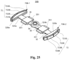
- Fig. 25 is a perspective view of a movable body in the pump according to the third embodiment of the present invention.
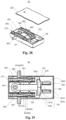
- Fig. 26 is a view showing a magnetic circuit configuration of the pump according to the third embodiment of the present invention.
- a pump 1B of the present embodiment has the same configuration as the configuration of the pump 1 of the first embodiment shown in Fig. 1 except that only the configuration of the magnetic circuit is modified.
- the same components are denoted by the same reference numbers and description for the same components will be omitted in the following description.
- the pump 1B has the same basic configuration as the basic configuration of the pump 1 of the first embodiment except the number of poles of a magnet 70B and the number of poles of a coil core portion 62B are different from corresponding ones of the pump 1.
- the pump 1B is configured so that a movable body 30B is provided in a case 21B of a fixed body 20B which has a rectangular planar shape so as to freely perform reciprocating rotation around a shaft portion 40B disposed at a center of the case 21B.
- Four-pole magnets 70B-1, 70B-2 are respectively provided at both end portions of the movable body 30B which are disposed so as to be perpendicular to an axial direction of the shaft portion 40B and are separated from each other in a longitudinal direction of the movable body 30B.
- coil core portions 62B-1, 62B-2 each having three core magnetic poles are provided in the case 21B and at positions respectively facing the magnets 70B-1, 70B-2 through an air gap.
- the magnets 70B-1, 70B-2 are respectively disposed along wall portions of the case 21B separated from each other in the longitudinal direction of the case 21B.
- the pump units 80a, 80b are provided in the case 21 along an extending direction of the movable body 30B so as to sandwich the movable body 30B in a depth direction of the case 21B.
- the movable walls 822 of the pump units 80a, 80b are respectively connected to pressing portions 35 of the movable body 30B which is configured in the same manner as the pressing portions 35 of the pump 1 or the pump 1A.
- coil core portion 62B-1 and the coil core portion 62B-2 have the same configuration, only the configuration of the coil core portion 62B-1 (sometimes referred to as "62B") will be described and description for the coil core portion 62B-2 will be omitted.
- the coil core portion 62B-1 has three coils 50B and a core portion 60B having an E-shape.
- the coil core portion 62B-1 is configured to have the same number of coils 50B as the number of core magnetic poles of the core portion 60B.
- the coils 50B are respectively wound around outer circumferences of three protrusions of the E-shaped core portion 60B through bobbins 65B.
- the three protrusions of the core portion 60B serve as core magnetic poles.
- the core magnetic poles 601B, 602B, 603B of the coil core portion 62B-1 are disposed in an arc track so as to face the magnet 70B-1.
- the coil core portion 62B-2 which is configured similarly to the coil core portion 62B-1 is disposed so as to be point-symmetrical around the shaft portion 40B with respect to the coil core portion 62B-1 with being separated from the coil core portion 62B-1 in the longitudinal direction of the case 21B. Further, the coil core portion 62B-2 is disposed so that the core magnetic poles 601B, 602B, 603B of the coil core portion 62B-2 face the magnet 70B-2.
- Magnetic pole surfaces 72 of the magnets 70B-1, 70B-2 are disposed so as to form an arc track outwardly protruding and are separated from each other in the longitudinal direction perpendicular to an axis of the shaft portion 40B.
- the core magnetic poles 601B to 603B of the core portions 60B of the coil core portions 62B-1, 62B-2 respectively face the magnets 70B-1, 70B-2.
- Each of the magnetic pole surfaces 72 of the magnets 70B-1, 70B-2 has magnetic poles 721B to 724B arranged in the rotation direction so that different polarities are alternately arranged.
- Magnetic attraction force is generated between the magnet 70B-1 and the core portion 60B of the coil core portion 62B-1 and between the magnet 70B-2 and the core portion 60B of the coil core portion 62B-2 and thus the magnetic attraction force functions as a magnetic spring. Namely, the magnetic spring due to the magnetic attraction force is generated at each of the end portions of the movable body 30B separated from each other in the longitudinal direction.
- the rotation of the movable body 30B around the shaft portion 40B is suppressed when the pump 1B is in the non-energized state, that is, in the normal state. More specifically, the core portions 60B-1, 60B-2 and the magnets 70B-1, 70B-2 attract each other due the magnetic attraction force at a position where the center core magnetic poles 601B of the core portions 60B of the coil core portions 602B-1, 62B-2 respectively face center portions of the two center magnetic poles 722B, 723B of the magnets 70B-1, 70B-2.
- the magnetic attraction force is generated between the core portion 60B-1 and the magnet 70B-1 and between the core portion 60B-2 and the magnet 70B-2. Since the two kinds of the magnetic attraction force generated in the longitudinal direction of the movable body 30B are generated on the same straight line in opposite directions with sandwiching the shaft portion 40B, the two kinds of the magnetic attraction force cancel each other.
- boundary surface positions (switching positions) between adjacent poles among the magnetic poles 721B, 722B, 723B, 724B of each of the magnet 70B-1, 70B-2 respectively coincide with center positions of the core magnetic poles 601B to 603B of the coil core portion 62B in the arc track of the rotation direction.
- a position of the movable body 30B for setting the above-described positional relationship is a rotation reference position. More specifically, the boundary surface position (switching positions) between the magnetic pole 721B, 722B faces the center position of the core magnetic pole 602B in the arc track of the rotation direction of the movable body 30B.
- the boundary surface position (switching positions) between the magnetic pole 722B, 723B faces the center position of the core magnetic pole 601B in the arc track of the rotation direction of the movable body 30B. Further, the boundary surface position (switching positions) between the magnetic pole 723B, 724B faces the center position of the core magnetic pole 603B in the arc track of the rotation direction of the movable body 30B.
- the magnet 70B-1 has four magnetic poles on the magnetic pole surface 72 facing the coil core portion 62B-1 and the four magnetic poles are aligned in the rotation direction so that different polarities are alternately arranged.
- the center two magnetic poles 722B, 723B are respectively the S pole and the N pole and the magnetic poles 721B, 724B sandwiching the center magnetic poles 722B, 723B are respectively the N pole and the S pole. Further, the magnetic poles 721B, 722B, 723B, 724B of the magnet 70B-1 face the magnetic poles 601B, 602B, 603B of the coil core portion 62B-1 (sometimes referred by "62B").
- the electrical current is supplied to each of the coils 50B of the coil core portion 62B to excite the core portion 60B.
- winding directions of the coils 50B, flow directions of the electrical current in the coils 50B or the like are set so that the polarity of the core magnetic pole 601B which is the center protrusion of the core portion 60B is different from the polarities of the core magnetic poles 602B, 603B adjacent to the core magnetic pole 601B on the both sides.
- winding directions of the coils 50B, flow directions of the electrical current in the coils 50B or the like are set so that the polarity of the core magnetic pole 601B which is the center protrusion of the core portion 60B is different from the polarities of the core magnetic poles 602B, 603B adjacent to the core magnetic pole 601B on the both sides.
- the core magnetic pole 601B which is the center protrusion of the core portion 60B is magnetized with the N pole and the core magnetic poles 602B, 603B of the core portion 60B are magnetized with the S pole. At this time, since the core magnetic poles 601B, 602B, 603B are excited by the corresponding coils 50B, it is possible to ensure a high driving output.
- the magnetic poles 722B, 723B of the magnet 70B facing the core magnetic pole 601B which is the N pole are respectively the S pole and the N pole.
- the magnetic pole 722B which is the S pole attracts the core magnetic pole 601B which is the N pole due to the magnetic attraction force and repels the magnetic pole 723B which is the N pole.
- the magnetic pole 721B of the magnet 70B is the N pole, the magnetic attraction force is generated between the magnetic pole 721B and the core magnetic pole 602B which is the S pole.
- the magnetic pole 724B of the magnet 70B which is the S pole repels the core magnetic pole 603B which is the S pole.
- thrust force in the direction F1 is generated between the magnet 70B and the coil core portion 62B and thus the movable body 30B is driven in the direction F1.
- the movable body 30B is located at the rotation reference position, that is a neutral position of the reciprocation movement by the magnetic attraction force of the magnetic springs.
- the electrical current is supplied to the coils 50B in the opposite direction to reverse the polarity of the core portion 60B, that is, the center core magnetic pole 601B of the core portion 60B facing the magnet 70B is magnetized with the S pole and the magnetic poles 602B, 603B are magnetized with the N pole.
- the magnet 70B facing the core portion 60B rotates in a direction opposite to the direction F1 (the direction -F1) and thus the movable body 30B is driven in the direction -F1 which is directly opposite to the direction F1.
- the relationship between the magnet 70B-2 and the coil core portion 62B-2 is point-symmetrical around the shaft portion 40B with respect to the relationship between the magnet 70B-1 and the coil core portion 62B-1.
- the relationship between the magnet 70B-2 and the coil core portion 62B-2 is the same as the relationship between the magnet 70B-1 and the coil core portion 62B-1. Therefore, it is possible to cause thrust force in the direction F1 or the direction -F1 between the magnet 70B-2 and the coil core portion 62B-2 as with the case of the thrust force between the magnet 70B-1 and the coil core portion 62B-1.
- the movable body 30B suitably performs the reciprocating rotation around the shaft portion 40B due to the magnetic attraction force and the repelling force effectively generated in the magnetic circuits at both end portions of the movable body 30B.
- the movable body 30B of the pump 1B including the magnets 70B-1, 70B-2 can perform the reciprocating movement (reciprocating vibration) in the vibration direction by changing the flow direction of the electrical current supplied in the coils 50B as described above similarly to the first embodiment.
- the driving principle and the pump performance of the pump 1B are the same as those of the pump 1 of the first embodiment indicated by the above equations (1), (2), (3), (4) and (5).
- the movable body 30B is elastically supported by the magnetic spring of the magnetic circuit provided by the magnet 70B-1 and the core portion 60B-1 and the magnetic spring of the magnetic circuit provided by the magnet 70B-2 and the core portion 60B-2. Further, the movable walls 822 are displaced by the reciprocating rotation of the movable body 30B caused by the resonance to drive the pump unit 80. Thus, it is possible to further reduce the thickness of the pump 1B as well as increase the output of the pump 1B, thereby ensuring the desired pressure and the desired flow rate of the pump 1B.
- the coil core portions 62B in the magnetic circuit of one side of the pump 1B has the three coils 50B, it is possible to disperse arrangement spaces for the coils 50B than a case where the number of coils 50B is one. As a result, it is possible to increase design flexibility of the coils and thus it is possible to increase the driving output of the pump 1B and reduce the thickness of the pump 1B.
- Fig. 27 is an external perspective view of a pump according to a fourth embodiment of the present invention.
- Fig. 28 is a perspective view showing an internal configuration of the pump according to the fourth embodiment of the present invention.
- Fig. 29 is a horizontal cross-sectional view showing the internal configuration of the pump according to the fourth embodiment of the present invention.
- Fig. 30 is an exploded perspective view of the pump according to the fourth embodiment of the present invention.
- Fig. 31 is a perspective view of a coil core portion in the pump according to the fourth embodiment of the present invention.
- Fig. 32 is a perspective view of a movable body in the pump according to the fourth embodiment of the present invention.
- a pump 1C has the same basic configuration as the configuration of the pump 1 of the first embodiment shown in Fig. 1 except that only the configuration of the magnetic circuit is modified.
- the same components are denoted by the same reference numbers and description for the same components will be omitted in the following description.
- Fig. 34 is an external perspective view of a pump according to a fifth embodiment of the present invention.
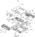
- Fig. 35 is an exploded perspective view of the pump according to the fifth embodiment of the present invention.
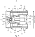
- Fig. 36 is a horizontal cross-sectional view showing an internal configuration of the pump according to the fifth embodiment of the present invention.
- Fig. 37 is an exploded perspective view of a pump unit in the pump according to the fifth embodiment of the present invention.
- Fig. 38 is a view showing an air flow path of the pump unit in the pump according to the fifth embodiment of the present invention.
- Fig. 39 is a schematic view which is referred to explain reciprocating rotational movement of a movable body in the pump unit according to the fifth embodiment of the present invention.
- a pump 1D of the present embodiment has the same basic configuration as the basic configuration of the pump 1 of the first embodiment shown in Fig. 1 except that a fixed body includes magnets and a movable body includes a coil core portion.
- a fixed body includes magnets
- a movable body includes a coil core portion.
- the pump 1D shown in Figs. 34 to 39 has the same basic configuration as the basic configuration of the pump 1 of the first embodiment except that a fixed body 20D includes magnets 70D (70D-1, 70D-2) and a movable body 30D includes a coil core portion 62D.
- the fixed body 20D of the pump 1D of the present embodiment includes a case 21D having a rectangular planar shape, a cover 22D for covering an opening portion of the case 21D opened toward the upper side, a pair of yokes 73 respectively provided on inner surfaces of wall portions of the case 21D separated from each other in a longitudinal direction of the case 21D, and a pair of magnets 70D-1, 70D-2 respectively provided on the pair of yokes 73. Further, a pair of pump units 80D are respectively provided on inner surfaces of wall portions of the case 21D separated from each other in a depth direction of the case 21D.
- the pair of pump units 80D are respectively disposed at positions sandwiching the movable body 30D in the depth direction of the case 21D, that is a reciprocating rotation (pivotal movement) direction of the movable body 30D with being separated from each other.
- each of the magnets 70D-1, 70D-2 has an arc shape corresponding to the arc-shaped surfaces of the pair of yokes 73.
- the magnets 70D-1, 70D-2 are respectively provided on the arc-shaped surfaces of the pair of yokes 73.
- Each of the magnets 70D-1, 70D-2 includes two magnetic poles 721D, 722D on its magnetic pole surface 72D facing the movable body 30D.
- the two magnetic poles 721D, 722D are aligned along the rotation (pivotal movement) direction of the movable body 30D and has different polarities. In one example shown in Fig.
- the magnetic pole 721D is the S pole and the magnetic pole 722D is the N pole.
- the fixed body 20D of the pump 1D of the present invention includes the magnets 70D-1, 70D-2 unlike the pumps 1, 1A, 1B, 1C of the first to fourth embodiments.
- the movable body main portion 32D includes the center opening portion 322 (see Fig. 3 ) in which the bearing portion 34 is fitted, and the arm portion 324a provided so as to extend from the movable body main portion 32D toward a direction perpendicular to an axial direction of the shaft portion 40D.
- Both of the movable body main portion 32D and the arm portion 324a are formed of magnetic material (ferromagnetic material) and integrated with each other.
- both end portions of the movable body 30D are magnetized with different polarities.
- the arm portion 324a of the movable body 30D serves as a core portion 60D around which the coil 50 is wound and the movable body 30D serves as the coil core portion 62D.
- both end portions of the movable body 30D are magnetized and thus serve as a core magnetic pole of the coil core portion 62D.
- the movable body 30D of the pump 1D of the present embodiment includes the coil core portion 62D.
- the coil core portion 62D is provided on the tip end portion of the arm portion 324a.
- the movable body 30D is provided in the case 21D so that the one end portion of the movable body 30D faces the magnet 70D-1 through an air gap in the direction perpendicular to the axial direction (rotational axis) of the shaft portion 40D and the other end portion of the movable body 30D faces the magnet 70D-2 through an air gap in the direction perpendicular to the axial direction (rotational axis) of the shaft portion 40D.
- both of the movable body main portion 32D and the arm portion 324a are formed of the magnetic material (ferromagnetic material), magnetic circuits are formed between the one end portion of the movable body 30D and the magnet 70D-1 and between the other end portion of the movable body 30D and the magnet 70D-2.
- Fig. 39A shows a state that the electrical current is supplied to the coil 50D to magnetize the one end portion of the movable body 30D facing the magnet 70D-1 with the S pole and magnetize the other end portion of the movable body 30D facing the magnet 70D-2 with the N pole. Further, Fig.
- the magnetic circuit is provided by the one end portion of the movable body 30D serving as the core magnetic pole of the coil core portion 62D and the magnet 70D-1.
- the other magnetic circuit is provided by the other one end portion of the movable body 30D serving as the core magnetic pole of the coil core portion 62D and the magnet 70D-2.
- the diaphragm portion 802 includes one insertion portion 822a and one movable wall 822.
- a chamber forming portion 824 of the cylinder portion 803 is provided on the rear side of the movable wall 822 which has flexibility and can be elastically deformed.
- the diaphragm portion 802 and the cylinder portion 803 are attached to each other so that a sealed chamber 82 which is a sealed space is formed by the movable wall 822 of the diaphragm portion 802 and the chamber forming portion 824 of the cylinder portion 803.
- Fig. 39A shows the state that the electrical current is supplied to the coil 50D to magnetize the one end portion of the movable body 30D facing the magnet 70D-1 with the S pole and magnetize the other end portion of the movable body 30D facing the magnet 70D-2 with the N pole.
- the one end portion of the movable body 30D which is the S pole repels the magnetic pole 721D of the magnet 70D-1 which is the S pole and attracts the magnetic pole 722D of the magnet 70D-1 which is the N pole.
- thrust force for rotating (pivotally rotating) the movable body 30D in the direction -F1 is generated at the one end portion of the movable body 30D.
- the other end portion of the movable body 30D which is the S pole repels the magnetic pole 721D of the magnet 70D-2 which is the S pole and attracts the magnetic pole 722D of the magnet 70D-2 which is the N pole.
- the thrust force for rotating (pivotally rotating) the movable body 30D in the direction -F1 is also generated at the other end portion of the movable body 30D.
- the movable body 30D can suitably perform the reciprocating rotation (pivotal movement) around the shaft portion 40D in the case 21D by supplying an alternating electrical current having a proper frequency into the coil 50D.
Landscapes
- Engineering & Computer Science (AREA)
- Mechanical Engineering (AREA)
- General Engineering & Computer Science (AREA)
- Physics & Mathematics (AREA)
- Electromagnetism (AREA)
- Power Engineering (AREA)
- Reciprocating Pumps (AREA)
Claims (13)
- Pumpe (1, 1A, 1B, 1C, 1D, 1E), umfassend:einen Schwingungsaktuator (10), der elektromagnetisch antreibbar ist; undeine Pumpeneinheit (80a, 80b, 80C, 80D) zum Ansaugen und Auslassen von Fluid aufgrund des elektromagnetischen Antriebs des Schwingungsaktuators (10),wobei der Schwingungsaktuator (10) Folgendes beinhaltet:einen festen Körper (20, 20A, 20B, 20D), an dem die Pumpeneinheit (80a, 80b, 80C, 80D) bereitgestellt ist, wobei der feste Körper (20, 20A, 20B, 20D) eines aus Folgendem enthält: einem Spulenkernabschnitt (62a, 62b, 62A-1, 62A-2, 62B-1, 62B-2, 62C, 62D), der eine Spule (50a, 50b, 50A, 50B, 50C, 50D) und einen Kernabschnitt (60a, 60b, 60A-1, 60A-2, 60B-1, 60B-2, 60C, 60D), um den die Spule (50a, 50b, 50A, 50B, 50C, 50D) gewickelt ist, aufweist, und einem Magneten (70a, 70b, 70A-1, 70A-2, 70B-1, 70B-2, 70C, 70D-1, 70D-2), der so angeordnet ist, dass er einem Endabschnitt des Kernabschnitts (60a, 60b, 60A-1, 60A-2, 60B-1, 60B-2, 60C, 60D) zugewandt ist,einen beweglichen Körper (30, 30A, 30B, 30C, 30D), der von der magnetischen Anziehungskraft des Magneten (70a, 70b, 70A-1, 70A-2, 70B-1, 70B-2, 70C, 70D-1, 70D-2) elastisch gehalten wird, wobei der bewegliche Körper (30, 30A, 30B, 30C, 30D) einen anderen aus dem Spulenkernabschnitt (62a, 62b, 62A-1, 62A-2, 62B-1, 62B-2, 62C, 62D) und dem Magneten (70a, 70b, 70A-1, 70A-2, 70B-1, 70B-2, 70C, 70D-1, 70D-2) enthält, undeinen Wellenabschnitt (40, 40A, 40B, 40C, 40D) zum Tragen des beweglichen Körpers (30, 30A, 30B, 30C, 30D), sodass der bewegliche Körper (30, 30A, 30B, 30C, 30D) eine hin- und hergehende Drehung durchführen kann,wobei die Pumpeneinheit (80a, 80b, 80C, 80D) Folgendes beinhaltet:eine bewegliche Wand (822), die durch die Drehbewegung des beweglichen Körpers (30, 30A, 30B, 30C, 30D) beweglich ist, undeine versiegelte Kammer (82), die mit einer Auslassöffnung (86) für das Fluid und einer Ansaugöffnung (83) für das Fluid in Verbindung gesetzt ist und deren Volumen durch Verschiebung der beweglichen Wand (822) verändert werden kann, undwobei der bewegliche Körper (30, 30A, 30B, 30C, 30D) Folgendes aufweist:einen Zusammendrückabschnitt (35), der in einer Bogenbahn um den Wellenabschnitt (40, 40A, 40B, 40C, 40D) herum beweglich ist und an der beweglichen Wand (822) anliegt, um die bewegliche Wand (822) zusammenzudrücken, wenn der bewegliche Körper (30, 30A, 30B, 30C, 30D) die hin- und hergehende Drehung durchführt, undeinen Armabschnitt (324a, 324b), der sich in eine Richtung senkrecht zu einer axialen Richtung des Wellenabschnitts (40, 40A, 40B, 40C, 40D) von einem Abschnitt (34) erstreckt, der axial von dem Wellenabschnitt (40, 40A, 40B, 40C, 40D) getragen wird, undgekennzeichnet dadurch, dass:der Armabschnitt (324a, 324b) Folgendes aufweist:ein rundes Loch (328), das durch den Armabschnitt (324a, 324b) in die axiale Richtung des Wellenabschnitts (40, 40A, 40B, 40C, 40D) verläuft, undein langes Loch (329), das durch den Armabschnitt (324a, 324b) in die axiale Richtung des Wellenabschnitts (40, 40A, 40B, 40C, 40D) verläuft und in die Richtung senkrecht zu der axialen Richtung des Wellenabschnitts (40, 40A, 40B, 40C, 40D) ausgedehnt ist,der Zusammendrückabschnitt (35) Folgendes aufweist:einen Wellenvorsprung (353), der axial an dem runden Loch (328) des Armabschnitts (324a, 324b) befestigt ist, undeinen Führungsvorsprung (352), der lose an dem langen Loch (329) des Armabschnitts (324a, 324b) angebracht ist,wobei der Zusammendrückabschnitt (35) die bewegliche Wand (822) linear zusammendrückt, wenn der bewegliche Körper, (30, 30A, 30B, 30C, 30D) die hin- und hergehende Drehung durchführt, unddie bewegliche Wand (822) in eine Bewegungsrichtung des Zusammendrückabschnitts (35) angeordnet ist und verschoben wird, wenn die bewegliche Wand (822) linear durch den Zusammendrückabschnitt (35) zusammengedrückt wird, um das Fluid in der versiegelten Kammer (82) durch die Auslassöffnung auszulassen.
- Pumpe (1, 1A, 1B, 1C, 1D, 1E) wie in Anspruch 1 beansprucht, wobei der andere aus dem Spulenkernabschnitt (62a, 62b, 62A-1, 62A-2, 62B-1, 62B-2, 62C, 62D) und dem Magneten (70a, 70b, 70A-1, 70A-2, 70B-1, 70B-2, 70C, 70D-1, 70D-2) an einem Endabschnitt des Armabschnitts (324a, 324b) bereitgestellt ist,wobei die versiegelte Kammer (82) ein Paar von versiegelten Kammern (82) enthält,wobei das Paar von versiegelten Kammern (82) so angeordnet ist, dass sie einander in einer Position zugewandt sind, die den Armabschnitt (324a, 324b) in einer hin- und hergehenden Drehrichtung des Armabschnitts (324a, 324b) sandwichartig anordnet,wobei die bewegliche Wand (822) ein Paar von beweglichen Wänden (822) enthält,wobei der Zusammendrückabschnitt (35) ein Paar von Schiebern (351) aufweist, die jeweils dem Paar von beweglichen Wänden (822) entsprechen, undwobei jede der beweglichen Wände (822) der versiegelten Kammer (82) linear von dem Schieber (351) zusammengedrückt wird, wenn der Armabschnitt (324a, 324b) eine hin- und hergehende Drehung durchführt.
- Pumpe (1, 1A, 1B, 1E) wie in Anspruch 1 beansprucht, wobei der Armabschnitt (324a, 324b) ein Paar von Armabschnitten (324a, 324b) enthält, die sich jeweils in entgegengesetzte Richtungen senkrecht zu der axialen Richtung des Wellenabschnitts (40, 40A, 40B) von dem Abschnitt (34), der axial von dem Wellenabschnitt (40, 40A, 40B) getragen wird, erstrecken,wobei der andere aus dem Spulenkernabschnitt (62a, 62b, 62A-1, 62A-2, 62B-1, 62B-2) und dem Magneten (70a, 70b, 70A-1, 70A-2, 70B-1, 70B-2) an einem Endabschnitt jedes der Armabschnitte (324a, 324b) bereitgestellt ist, undwobei der eine aus dem Spulenkernabschnitt (62a, 62b, 62A-1, 62A-2, 62B-1, 62B-2) und dem Magneten (70a, 70b, 70A-1, 70A-2, 70B-1, 70B-2) an dem festen Körper (20, 20A, 20B) so bereitgestellt ist, dass er dem anderen aus dem Spulenkernabschnitt (62a, 62b, 62A-1, 62A-2, 62B-1, 62B-2) und dem Magneten (70a, 70b, 70A-1, 70A-2, 70B-1, 70B-2) zugewandt ist,wobei die versiegelte Kammer (82) ein Paar von versiegelten Kammern (82) enthält,wobei das Paar von versiegelten Kammern (82) nebeneinander entlang einer sich erstreckenden Richtung des Paares von Armabschnitten (324a, 324b) angeordnet ist,wobei die bewegliche Wand (822) ein Paar von beweglichen Wänden (822) enthält,wobei der Zusammendrückabschnitt (35) ein Paar von Schiebern (351) aufweist, die jeweils dem Paar von beweglichen Wänden (822) entsprechen, undwobei jede der beweglichen Wände (822) der versiegelten Kammer (82) linear von dem Schieber (351) zusammengedrückt wird, wenn die Armabschnitte (324a, 324b) eine hin- und hergehende Drehung durchführen.
- Pumpe (1, 1A, 1B, 1E) wie in Anspruch 3 beansprucht, wobei die Auslassöffnungen (86) des Paares von versiegelten Kammern (82) miteinander verbunden sind.
- Pumpe (1, 1A, 1B, 1C, 1D, 1E) wie in einem der Ansprüche 2 bis 4 beansprucht, wobei die Schieber (351) jeweils mit den beweglichen Wänden (822) verbunden sind.
- Pumpe (1, 1A, 1B, 1C, 1D, 1E) wie in einem der Ansprüche 1 bis 5 beansprucht, wobei der Magnet (70a, 70b, 70A-1, 70A-2, 70B-1, 70B-2, 70C, 70D-1, 70D-2) an einem aus dem beweglichen Körper (30, 30A, 30B, 30C, 30D) und dem festen Körper (20, 20A, 20B, 20D) bereitgestellt ist und zusammen mit dem Kernabschnitt (60a, 60b, 60A-1, 60A-2, 60B-1, 60B-2, 60C, 60D) des Spulenkernabschnitts (62a, 62b, 62A-1, 62A-2, 62B-1, 62B-2, 62C, 62D), der an einem anderen aus dem beweglichen Körper (30, 30A, 30B, 30C, 30D) und dem festen Körper (20, 20A, 20B, 20D) bereitgestellt ist, eine magnetische Feder ausbildet.
- Pumpe (1, 1A, 1B, 1E) wie in einem der Ansprüche 1 bis 6 beansprucht, wobei der Magnet (70a, 70b, 70A-1, 70A-2, 70B-1, 70B-2) so magnetisiert ist, dass er drei magnetische Pole (721, 722, 723) aufweist, und
wobei die Spule (50a, 50b, 50A, 50B) um den Kernabschnitt (60a, 60b, 60A-1, 60A-2, 60B-1, 60B-2) des Spulenkernabschnitts (62a, 62b, 62A-1, 62A-2, 62B-1, 62B-2) gewickelt ist und der Kernabschnitt (60a, 60b, 60A-1, 60A-2, 60B-1, 60B-2) des Spulenkernabschnitts (62a, 62b, 62A-1, 62A-2, 62B-1, 62B-2) zwei magnetische Pole (602a, 602b, 603a, 603b, 601A, 602A, 603A) aufweist, die dem Magneten (70a, 70b, 70A-1, 70A-2, 70B-1, 70B-2) in einer Magnetisierungsrichtung des Magneten (70a, 70b, 70A-1, 70A-2, 70B-1, 70B-2) zugewandt sind. - Pumpe (1A, 1B, 1E) wie in einem der Ansprüche 1 bis 6 beansprucht, wobei der Magnet (70A-1, 70A-2, 70B-1, 70B-2) so magnetisiert ist, dass er vier magnetische Pole (721A, 722A, 723A, 724A, 721B, 722B, 723B, 724B) aufweist, und
wobei die Spule (50A, 50B) um den Kernabschnitt (60a, 60b) des Spulenkernabschnitts (62a, 62b) gewickelt ist und der Kernabschnitt (60a, 60b) des Spulenkernabschnitts (62a, 62b) drei magnetische Pole (601A, 602A, 603A, 601B, 602B, 603B) aufweist, die dem Magneten (70A-1, 70A-2, 70B-1, 70B-2) in einer Magnetisierungsrichtung des Magneten (70A-1, 70A-2, 70B-1, 70B-2) zugewandt sind. - Pumpe (1B, 1E) wie in einem der Ansprüche 1 bis 6 beansprucht, wobei der Magnet (70B-1, 70B-2) so magnetisiert ist, dass er vier magnetische Pole (721B, 722B, 723B, 724B) aufweist,wobei die Spule (50B) drei Spulen (50B) enthält, undwobei die drei Spulen (50B) um den Kernabschnitt (60B-1, 60B-2) des Spulenkernabschnitts (62B-1, 62B-2) gewickelt sind und der Kernabschnitt (60B-1, 60B-2) des Spulenkernabschnitts (62B-1, 62B-2) drei magnetische Pole (601B, 602B, 603B) aufweist, die dem Magneten (70B-1, 70B-2) in einer Magnetisierungsrichtung des Magneten (70B-1, 70B-2) zugewandt sind.
- Pumpe (1C, 1D, 1E) wie in einem der Ansprüche 1 bis 6 beansprucht, wobei der bewegliche Körper (30C, 30D) einen Endabschnitt, der axial von dem Wellenabschnitt (40C, 40D) so getragen wird, dass der bewegliche Körper (30C, 30D) die hin- und hergehende Drehung durchführen kann, und einen anderen Endabschnitt, an dem der andere aus dem Kernabschnitt (62C, 62D) und dem Magneten (70C, 70D-2) bereitgestellt ist, aufweist,wobei der feste Körper (20D) den einen aus dem Spulenkernabschnitt (30C, 30D) und dem Magneten (70C, 70D-2) aufweist, der dem anderen aus dem Spulenkernabschnitt (30C, 30D) und dem Magneten (70a, 70b, 70A-1, 70A-2, 70B-1, 70B-2, 70C, 70D-1, 70D-2) in eine Richtung senkrecht zu einer Drehachse des beweglichen Körpers (30, 30A, 30B, 30C, 30D) zugewandt ist, undwobei der Magnet (70C, 70D-2) so magnetisiert ist, dass er zwei magnetische Pole (721C, 722C, 721D, 722D) aufweist.
- Pumpe (1C, 1E) wie in Anspruch 10 beansprucht, wobei der Kernabschnitt (50C) drei magnetische Pole (601C, 602C, 603C) aufweist, um die die Spule (50C) gewickelt ist.
- Pumpe (1D, 1E) wie in Anspruch 1 oder 2 beansprucht, wobei der bewegliche Körper (30D) einen Endabschnitt aufweist, der axial von dem Wellenabschnitt (40D) so getragen wird, dass der bewegliche Körper (30D) die hin- und hergehende Drehung durchführen kann, und ferner den Spulenkernabschnitt (62D) enthält, und
wobei der feste Körper (20D) den Magneten (70D-2, 721D, 722D) enthält, der dem Spulenkernabschnitt (62D) in einer Richtung senkrecht zu einer Drehachse des beweglichen Körpers (30D) zugewandt ist. - Luftzuführvorrichtung, umfassend: die Pumpe (1, 1A, 1B, 1C, 1D, 1E), die durch einen der Ansprüche 1 bis 12 definiert ist.
Applications Claiming Priority (2)
| Application Number | Priority Date | Filing Date | Title |
|---|---|---|---|
| JP2020064594 | 2020-03-31 | ||
| PCT/JP2021/012112 WO2021200424A1 (ja) | 2020-03-31 | 2021-03-24 | ポンプ及び空気供給装置 |
Publications (3)
| Publication Number | Publication Date |
|---|---|
| EP4112935A1 EP4112935A1 (de) | 2023-01-04 |
| EP4112935A4 EP4112935A4 (de) | 2024-07-24 |
| EP4112935B1 true EP4112935B1 (de) | 2025-07-09 |
Family
ID=77928645
Family Applications (1)
| Application Number | Title | Priority Date | Filing Date |
|---|---|---|---|
| EP21780810.4A Active EP4112935B1 (de) | 2020-03-31 | 2021-03-24 | Pumpe und luftzufuhrvorrichtung |
Country Status (5)
| Country | Link |
|---|---|
| US (1) | US12352257B2 (de) |
| EP (1) | EP4112935B1 (de) |
| JP (1) | JP7701111B2 (de) |
| CN (1) | CN115427686A (de) |
| WO (1) | WO2021200424A1 (de) |
Families Citing this family (1)
| Publication number | Priority date | Publication date | Assignee | Title |
|---|---|---|---|---|
| JP7632970B2 (ja) | 2021-03-30 | 2025-02-19 | ミネベアミツミ株式会社 | ポンプシステムおよび電子機器 |
Family Cites Families (17)
| Publication number | Priority date | Publication date | Assignee | Title |
|---|---|---|---|---|
| DE1846719U (de) * | 1961-12-23 | 1962-02-15 | Erwin Kolfertz | Elektrische doppelmembranpumpe. |
| JPS5139813U (de) * | 1974-09-19 | 1976-03-25 | ||
| JPS60142073A (ja) * | 1983-12-28 | 1985-07-27 | Nippon Suisou Kogyo Kk | エア−ポンプ |
| FR2767611B1 (fr) * | 1997-08-22 | 1999-10-29 | Sonceboz | Actionneur electromagnetique a deux pieces mobiles en opposition de phase |
| GB2339336B (en) * | 1998-06-16 | 2000-08-16 | Huntleigh Technology Plc | Magnetic actuator |
| JP4617554B2 (ja) | 2000-09-28 | 2011-01-26 | ミツミ電機株式会社 | 小型ポンプ |
| CN1420272A (zh) * | 2001-11-19 | 2003-05-28 | 张纪永 | 皮囊式真空、水循环泵 |
| DE10330978A1 (de) | 2003-07-09 | 2005-02-10 | Braun Gmbh | Elektrisches Kleingerät mit einem Elektromotor zur Erzeugung einer oszillierenden Bewegung |
| JP2009240044A (ja) | 2008-03-26 | 2009-10-15 | Panasonic Electric Works Co Ltd | 電磁アクチュエータ及び電気式かみそり |
| DE202013000479U1 (de) * | 2013-01-18 | 2014-05-05 | Schwarzer Precision GmbH & Co. KG | Membranpumpe |
| JP6287546B2 (ja) * | 2014-04-25 | 2018-03-07 | ミツミ電機株式会社 | アクチュエータ及びエアポンプ、理美容機器及びレーザー走査機器 |
| CN105610296B (zh) * | 2016-02-19 | 2018-09-07 | 胡建坤 | 隔膜泵及电动喷雾器 |
| JP6853542B2 (ja) * | 2017-04-24 | 2021-03-31 | 胡建坤 | 揺動モータに使用される制御方法および揺動モータ |
| JP6925028B2 (ja) * | 2017-05-18 | 2021-08-25 | 株式会社テクノ高槻 | 電磁振動型ダイヤフラムポンプ及び電磁振動型ダイヤフラムポンプの固定方法 |
| FR3069119B1 (fr) * | 2017-07-11 | 2019-08-30 | Commissariat A L'energie Atomique Et Aux Energies Alternatives | Convertisseur d'energie electromagnetique |
| JP2019075966A (ja) | 2017-10-13 | 2019-05-16 | 孝仁 今川 | 往復運動モーター |
| JP7248387B2 (ja) * | 2018-07-11 | 2023-03-29 | ミネベアミツミ株式会社 | 振動アクチュエーター及び電子機器 |
-
2021
- 2021-03-24 CN CN202180025214.2A patent/CN115427686A/zh active Pending
- 2021-03-24 JP JP2022512002A patent/JP7701111B2/ja active Active
- 2021-03-24 US US17/907,658 patent/US12352257B2/en active Active
- 2021-03-24 EP EP21780810.4A patent/EP4112935B1/de active Active
- 2021-03-24 WO PCT/JP2021/012112 patent/WO2021200424A1/ja not_active Ceased
Also Published As
| Publication number | Publication date |
|---|---|
| US12352257B2 (en) | 2025-07-08 |
| CN115427686A (zh) | 2022-12-02 |
| EP4112935A1 (de) | 2023-01-04 |
| WO2021200424A1 (ja) | 2021-10-07 |
| JPWO2021200424A1 (de) | 2021-10-07 |
| JP7701111B2 (ja) | 2025-07-01 |
| EP4112935A4 (de) | 2024-07-24 |
| US20230151805A1 (en) | 2023-05-18 |
Similar Documents
| Publication | Publication Date | Title |
|---|---|---|
| JP4567409B2 (ja) | 共振駆動アクチュエータ | |
| EP3358727B1 (de) | Transversalfluss-hubkolbenmotor und hubkolbenverdichter damit | |
| JP6795945B2 (ja) | リニアモータ及びリニアモータを有する圧縮機 | |
| US20110274571A1 (en) | Electromagnetic reciprocating fluid device | |
| US6657326B1 (en) | Efficient cylindrical linear motor | |
| KR20060003092A (ko) | 왕복직선구동 액츄에이터 및 그를 이용한 전동칫솔 | |
| KR20030068477A (ko) | 리니어 모터 및 리니어 압축기 | |
| US20190245425A1 (en) | Transverse flux type linear motor and linear compressor having the same | |
| EP4112193A1 (de) | Pumpensteuerungsvorrichtung und pumpensteuerungssystem | |
| JP3508523B2 (ja) | 鉄心可動型リニア振動子及びリニア圧縮機 | |
| EP4112935A1 (de) | Pumpe und luftzufuhrvorrichtung | |
| JP3816814B2 (ja) | 往復動式圧縮機のモータ構造 | |
| CN210297519U (zh) | 动芯式往复电动机和具有动芯式往复电动机的往复压缩机 | |
| JP2004023911A (ja) | リニアアクチュエータ、それを用いたポンプ装置並びにコンプレッサー装置 | |
| CN211830532U (zh) | 线性马达以及具有该线性马达的线性压缩机 | |
| JP2000299971A (ja) | 電磁駆動機構および該機構を用いた電磁振動型ポンプ | |
| KR20040002523A (ko) | 진동형 리니어 액츄에이터 | |
| KR102021862B1 (ko) | 리니어 모터 및 이를 구비한 리니어 압축기 | |
| JP2005273477A (ja) | 電磁式ダイヤフラムポンプ | |
| JP4047317B2 (ja) | ステッピングモータ | |
| WO2019017028A1 (ja) | 往復動式リニアモータ | |
| JP2004064838A (ja) | リニアアクチュエータ、それを用いたポンプ装置並びにコンプレッサー装置 | |
| JPH0759947B2 (ja) | 円筒形電磁振動ポンプ | |
| JP2007520981A (ja) | リニア振動アクチュエータの可動子 | |
| JP2005351151A (ja) | 電磁式ポンプ |
Legal Events
| Date | Code | Title | Description |
|---|---|---|---|
| STAA | Information on the status of an ep patent application or granted ep patent |
Free format text: STATUS: THE INTERNATIONAL PUBLICATION HAS BEEN MADE |
|
| PUAI | Public reference made under article 153(3) epc to a published international application that has entered the european phase |
Free format text: ORIGINAL CODE: 0009012 |
|
| STAA | Information on the status of an ep patent application or granted ep patent |
Free format text: STATUS: REQUEST FOR EXAMINATION WAS MADE |
|
| 17P | Request for examination filed |
Effective date: 20220928 |
|
| AK | Designated contracting states |
Kind code of ref document: A1 Designated state(s): AL AT BE BG CH CY CZ DE DK EE ES FI FR GB GR HR HU IE IS IT LI LT LU LV MC MK MT NL NO PL PT RO RS SE SI SK SM TR |
|
| DAV | Request for validation of the european patent (deleted) | ||
| DAX | Request for extension of the european patent (deleted) | ||
| A4 | Supplementary search report drawn up and despatched |
Effective date: 20240620 |
|
| RIC1 | Information provided on ipc code assigned before grant |
Ipc: H02K 33/16 20060101ALI20240614BHEP Ipc: B06B 1/04 20060101ALI20240614BHEP Ipc: F04B 45/04 20060101ALI20240614BHEP Ipc: F04B 45/047 20060101AFI20240614BHEP |
|
| GRAP | Despatch of communication of intention to grant a patent |
Free format text: ORIGINAL CODE: EPIDOSNIGR1 |
|
| STAA | Information on the status of an ep patent application or granted ep patent |
Free format text: STATUS: GRANT OF PATENT IS INTENDED |
|
| INTG | Intention to grant announced |
Effective date: 20250212 |
|
| GRAS | Grant fee paid |
Free format text: ORIGINAL CODE: EPIDOSNIGR3 |
|
| GRAA | (expected) grant |
Free format text: ORIGINAL CODE: 0009210 |
|
| STAA | Information on the status of an ep patent application or granted ep patent |
Free format text: STATUS: THE PATENT HAS BEEN GRANTED |
|
| AK | Designated contracting states |
Kind code of ref document: B1 Designated state(s): AL AT BE BG CH CY CZ DE DK EE ES FI FR GB GR HR HU IE IS IT LI LT LU LV MC MK MT NL NO PL PT RO RS SE SI SK SM TR |
|
| REG | Reference to a national code |
Ref country code: GB Ref legal event code: FG4D |
|
| REG | Reference to a national code |
Ref country code: CH Ref legal event code: EP |
|
| REG | Reference to a national code |
Ref country code: IE Ref legal event code: FG4D |
|
| REG | Reference to a national code |
Ref country code: DE Ref legal event code: R096 Ref document number: 602021033863 Country of ref document: DE |
|
| P01 | Opt-out of the competence of the unified patent court (upc) registered |
Free format text: CASE NUMBER: UPC_APP_3787_4112935/2025 Effective date: 20250820 |
|
| REG | Reference to a national code |
Ref country code: NL Ref legal event code: MP Effective date: 20250709 |
|
| PG25 | Lapsed in a contracting state [announced via postgrant information from national office to epo] |
Ref country code: PT Free format text: LAPSE BECAUSE OF FAILURE TO SUBMIT A TRANSLATION OF THE DESCRIPTION OR TO PAY THE FEE WITHIN THE PRESCRIBED TIME-LIMIT Effective date: 20251110 |
|
| PG25 | Lapsed in a contracting state [announced via postgrant information from national office to epo] |
Ref country code: NL Free format text: LAPSE BECAUSE OF FAILURE TO SUBMIT A TRANSLATION OF THE DESCRIPTION OR TO PAY THE FEE WITHIN THE PRESCRIBED TIME-LIMIT Effective date: 20250709 |
|
| REG | Reference to a national code |
Ref country code: AT Ref legal event code: MK05 Ref document number: 1812027 Country of ref document: AT Kind code of ref document: T Effective date: 20250709 |
|
| PG25 | Lapsed in a contracting state [announced via postgrant information from national office to epo] |
Ref country code: IS Free format text: LAPSE BECAUSE OF FAILURE TO SUBMIT A TRANSLATION OF THE DESCRIPTION OR TO PAY THE FEE WITHIN THE PRESCRIBED TIME-LIMIT Effective date: 20251109 |
|
| PG25 | Lapsed in a contracting state [announced via postgrant information from national office to epo] |
Ref country code: NO Free format text: LAPSE BECAUSE OF FAILURE TO SUBMIT A TRANSLATION OF THE DESCRIPTION OR TO PAY THE FEE WITHIN THE PRESCRIBED TIME-LIMIT Effective date: 20251009 |
|
| REG | Reference to a national code |
Ref country code: LT Ref legal event code: MG9D |
|
| PG25 | Lapsed in a contracting state [announced via postgrant information from national office to epo] |
Ref country code: AT Free format text: LAPSE BECAUSE OF FAILURE TO SUBMIT A TRANSLATION OF THE DESCRIPTION OR TO PAY THE FEE WITHIN THE PRESCRIBED TIME-LIMIT Effective date: 20250709 |
|
| PG25 | Lapsed in a contracting state [announced via postgrant information from national office to epo] |
Ref country code: FI Free format text: LAPSE BECAUSE OF FAILURE TO SUBMIT A TRANSLATION OF THE DESCRIPTION OR TO PAY THE FEE WITHIN THE PRESCRIBED TIME-LIMIT Effective date: 20250709 |
|
| PG25 | Lapsed in a contracting state [announced via postgrant information from national office to epo] |
Ref country code: HR Free format text: LAPSE BECAUSE OF FAILURE TO SUBMIT A TRANSLATION OF THE DESCRIPTION OR TO PAY THE FEE WITHIN THE PRESCRIBED TIME-LIMIT Effective date: 20250709 |
|
| PG25 | Lapsed in a contracting state [announced via postgrant information from national office to epo] |
Ref country code: GR Free format text: LAPSE BECAUSE OF FAILURE TO SUBMIT A TRANSLATION OF THE DESCRIPTION OR TO PAY THE FEE WITHIN THE PRESCRIBED TIME-LIMIT Effective date: 20251010 |
|
| PG25 | Lapsed in a contracting state [announced via postgrant information from national office to epo] |
Ref country code: SE Free format text: LAPSE BECAUSE OF FAILURE TO SUBMIT A TRANSLATION OF THE DESCRIPTION OR TO PAY THE FEE WITHIN THE PRESCRIBED TIME-LIMIT Effective date: 20250709 |
|
| PG25 | Lapsed in a contracting state [announced via postgrant information from national office to epo] |
Ref country code: LV Free format text: LAPSE BECAUSE OF FAILURE TO SUBMIT A TRANSLATION OF THE DESCRIPTION OR TO PAY THE FEE WITHIN THE PRESCRIBED TIME-LIMIT Effective date: 20250709 |
|
| PG25 | Lapsed in a contracting state [announced via postgrant information from national office to epo] |
Ref country code: BG Free format text: LAPSE BECAUSE OF FAILURE TO SUBMIT A TRANSLATION OF THE DESCRIPTION OR TO PAY THE FEE WITHIN THE PRESCRIBED TIME-LIMIT Effective date: 20250709 Ref country code: PL Free format text: LAPSE BECAUSE OF FAILURE TO SUBMIT A TRANSLATION OF THE DESCRIPTION OR TO PAY THE FEE WITHIN THE PRESCRIBED TIME-LIMIT Effective date: 20250709 |
|
| PG25 | Lapsed in a contracting state [announced via postgrant information from national office to epo] |
Ref country code: RS Free format text: LAPSE BECAUSE OF FAILURE TO SUBMIT A TRANSLATION OF THE DESCRIPTION OR TO PAY THE FEE WITHIN THE PRESCRIBED TIME-LIMIT Effective date: 20251009 |
|
| PG25 | Lapsed in a contracting state [announced via postgrant information from national office to epo] |
Ref country code: ES Free format text: LAPSE BECAUSE OF FAILURE TO SUBMIT A TRANSLATION OF THE DESCRIPTION OR TO PAY THE FEE WITHIN THE PRESCRIBED TIME-LIMIT Effective date: 20250709 |
|
| PG25 | Lapsed in a contracting state [announced via postgrant information from national office to epo] |
Ref country code: SM Free format text: LAPSE BECAUSE OF FAILURE TO SUBMIT A TRANSLATION OF THE DESCRIPTION OR TO PAY THE FEE WITHIN THE PRESCRIBED TIME-LIMIT Effective date: 20250709 |
|
| PG25 | Lapsed in a contracting state [announced via postgrant information from national office to epo] |
Ref country code: DK Free format text: LAPSE BECAUSE OF FAILURE TO SUBMIT A TRANSLATION OF THE DESCRIPTION OR TO PAY THE FEE WITHIN THE PRESCRIBED TIME-LIMIT Effective date: 20250709 |
|
| PG25 | Lapsed in a contracting state [announced via postgrant information from national office to epo] |
Ref country code: IT Free format text: LAPSE BECAUSE OF FAILURE TO SUBMIT A TRANSLATION OF THE DESCRIPTION OR TO PAY THE FEE WITHIN THE PRESCRIBED TIME-LIMIT Effective date: 20250709 |
|
| PG25 | Lapsed in a contracting state [announced via postgrant information from national office to epo] |
Ref country code: CZ Free format text: LAPSE BECAUSE OF FAILURE TO SUBMIT A TRANSLATION OF THE DESCRIPTION OR TO PAY THE FEE WITHIN THE PRESCRIBED TIME-LIMIT Effective date: 20250709 |
|
| PG25 | Lapsed in a contracting state [announced via postgrant information from national office to epo] |
Ref country code: EE Free format text: LAPSE BECAUSE OF FAILURE TO SUBMIT A TRANSLATION OF THE DESCRIPTION OR TO PAY THE FEE WITHIN THE PRESCRIBED TIME-LIMIT Effective date: 20250709 Ref country code: SK Free format text: LAPSE BECAUSE OF FAILURE TO SUBMIT A TRANSLATION OF THE DESCRIPTION OR TO PAY THE FEE WITHIN THE PRESCRIBED TIME-LIMIT Effective date: 20250709 |
|
| PLBE | No opposition filed within time limit |
Free format text: ORIGINAL CODE: 0009261 |
|
| STAA | Information on the status of an ep patent application or granted ep patent |
Free format text: STATUS: NO OPPOSITION FILED WITHIN TIME LIMIT |