EP4108902A1 - Kolben für einen verbrennungsmotor und verfahren zur herstellung davon - Google Patents
Kolben für einen verbrennungsmotor und verfahren zur herstellung davon Download PDFInfo
- Publication number
- EP4108902A1 EP4108902A1 EP22157853.7A EP22157853A EP4108902A1 EP 4108902 A1 EP4108902 A1 EP 4108902A1 EP 22157853 A EP22157853 A EP 22157853A EP 4108902 A1 EP4108902 A1 EP 4108902A1
- Authority
- EP
- European Patent Office
- Prior art keywords
- piston
- anodized film
- crown surface
- recess
- internal combustion
- Prior art date
- Legal status (The legal status is an assumption and is not a legal conclusion. Google has not performed a legal analysis and makes no representation as to the accuracy of the status listed.)
- Granted
Links
Images


Classifications
-
- F—MECHANICAL ENGINEERING; LIGHTING; HEATING; WEAPONS; BLASTING
- F02—COMBUSTION ENGINES; HOT-GAS OR COMBUSTION-PRODUCT ENGINE PLANTS
- F02F—CYLINDERS, PISTONS OR CASINGS, FOR COMBUSTION ENGINES; ARRANGEMENTS OF SEALINGS IN COMBUSTION ENGINES
- F02F3/00—Pistons
- F02F3/10—Pistons having surface coverings
- F02F3/12—Pistons having surface coverings on piston heads
-
- C—CHEMISTRY; METALLURGY
- C25—ELECTROLYTIC OR ELECTROPHORETIC PROCESSES; APPARATUS THEREFOR
- C25D—PROCESSES FOR THE ELECTROLYTIC OR ELECTROPHORETIC PRODUCTION OF COATINGS; ELECTROFORMING; APPARATUS THEREFOR
- C25D11/00—Electrolytic coating by surface reaction, i.e. forming conversion layers
- C25D11/02—Anodisation
- C25D11/022—Anodisation on selected surface areas
-
- C—CHEMISTRY; METALLURGY
- C25—ELECTROLYTIC OR ELECTROPHORETIC PROCESSES; APPARATUS THEREFOR
- C25D—PROCESSES FOR THE ELECTROLYTIC OR ELECTROPHORETIC PRODUCTION OF COATINGS; ELECTROFORMING; APPARATUS THEREFOR
- C25D11/00—Electrolytic coating by surface reaction, i.e. forming conversion layers
- C25D11/02—Anodisation
- C25D11/024—Anodisation under pulsed or modulated current or potential
-
- C—CHEMISTRY; METALLURGY
- C25—ELECTROLYTIC OR ELECTROPHORETIC PROCESSES; APPARATUS THEREFOR
- C25D—PROCESSES FOR THE ELECTROLYTIC OR ELECTROPHORETIC PRODUCTION OF COATINGS; ELECTROFORMING; APPARATUS THEREFOR
- C25D11/00—Electrolytic coating by surface reaction, i.e. forming conversion layers
- C25D11/02—Anodisation
- C25D11/04—Anodisation of aluminium or alloys based thereon
- C25D11/16—Pretreatment, e.g. desmutting
-
- F—MECHANICAL ENGINEERING; LIGHTING; HEATING; WEAPONS; BLASTING
- F02—COMBUSTION ENGINES; HOT-GAS OR COMBUSTION-PRODUCT ENGINE PLANTS
- F02F—CYLINDERS, PISTONS OR CASINGS, FOR COMBUSTION ENGINES; ARRANGEMENTS OF SEALINGS IN COMBUSTION ENGINES
- F02F3/00—Pistons
- F02F3/10—Pistons having surface coverings
-
- C—CHEMISTRY; METALLURGY
- C25—ELECTROLYTIC OR ELECTROPHORETIC PROCESSES; APPARATUS THEREFOR
- C25D—PROCESSES FOR THE ELECTROLYTIC OR ELECTROPHORETIC PRODUCTION OF COATINGS; ELECTROFORMING; APPARATUS THEREFOR
- C25D11/00—Electrolytic coating by surface reaction, i.e. forming conversion layers
- C25D11/02—Anodisation
- C25D11/04—Anodisation of aluminium or alloys based thereon
- C25D11/06—Anodisation of aluminium or alloys based thereon characterised by the electrolytes used
- C25D11/08—Anodisation of aluminium or alloys based thereon characterised by the electrolytes used containing inorganic acids
-
- C—CHEMISTRY; METALLURGY
- C25—ELECTROLYTIC OR ELECTROPHORETIC PROCESSES; APPARATUS THEREFOR
- C25D—PROCESSES FOR THE ELECTROLYTIC OR ELECTROPHORETIC PRODUCTION OF COATINGS; ELECTROFORMING; APPARATUS THEREFOR
- C25D11/00—Electrolytic coating by surface reaction, i.e. forming conversion layers
- C25D11/02—Anodisation
- C25D11/04—Anodisation of aluminium or alloys based thereon
- C25D11/06—Anodisation of aluminium or alloys based thereon characterised by the electrolytes used
- C25D11/10—Anodisation of aluminium or alloys based thereon characterised by the electrolytes used containing organic acids
Definitions
- the present invention relates to a piston for an internal combustion engine and a method for manufacturing the same, and more particularly, relates to a piston for an internal combustion engine having an anodized film on a piston crown surface, and a method for manufacturing the same.
- Patent Literature 1 discloses an internal combustion engine in which an anodized film is formed on a part of, or the entirety of, an aluminum-based wall surface facing a combustion chamber.
- the anodized film has a film thickness in the range of 30 to 170 ⁇ m and includes a first micropore with a micrometer-size diameter and a nanopore with a nanometer-size diameter that extend inward from the surface of the anodized film in the thickness direction or substantially the thickness direction of the anodized film, and a second micropore with a micrometer-size diameter inside the anodized film, the first micropore and the nanopore being sealed with a sealing substance converted from a sealant, and the second micropore being not sealed.
- Patent Literature 1 Even if the anodized film having the micropores and nanopores sealed therein as in Patent Literature 1 has good thermal properties, when such anodized film is adopted for the crown surface of a piston for an internal combustion engine, the original thermal properties cannot be maintained when the internal combustion engine is run continuously, due to the pores in the film being sealed. Consequently, heat retention causes knocking.
- an object of the present invention is to provide a piston for an internal combustion engine in which an anodized film is formed on a piston crown surface, the anodized film having low thermal conductivity and volume specific heat capacity, excellent durability, and the ability to suppress heat retention even during a continuous run of an internal combustion engine.
- the present invention also aims to provide a method for manufacturing the piston.
- one aspect of the present invention is a method for manufacturing a piston for an internal combustion engine, the method including the steps of: irradiating a piston crown surface of a piston body made of aluminum alloy with laser light to form a recess in a part of the piston crown surface irradiated with the laser light; and forming an anodized film on the piston crown surface by an anodizing treatment to close an opening of the recess, whereby manufacturing the piston having a hollow space closed with the anodized film inside the recess.
- a piston for an internal combustion engine including: a piston body having a piston crown surface and made of aluminum alloy; and an anodized film covering the piston crown surface.
- the piston crown surface of the piston body including a plurality of recesses. Cells of the anodized film extending in random directions with respect to a surface of the piston crown surface and surfaces inside the plurality of recesses and surround a periphery of silicon in the anodized film while branching in random directions. Openings of the plurality of recesses are closed with the anodized film, and the piston has a hollow space closed with the anodized film inside each of the plurality of recesses.
- the plurality of recesses are formed on the piston crown surface of the piston body made of aluminum alloy, and the anodized film is formed on the piston crown surface so as to close the openings of the recesses, whereby the hollow spaces each closed with the anodized film are present inside the recesses.
- an anodized film having low thermal conductivity, volume specific heat capacity, and excellent durability can be formed on the piston crown surface.
- the pores in the anodized film are not sealed, heat retention can be suppressed even in a continuous run of the internal combustion engine.
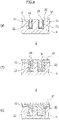
- a method for manufacturing the piston for an internal combustion engine includes a laser irradiation step of irradiating a piston crown surface 2 of a piston body made of aluminum alloy with laser light X, to form a recess 10 in a part of the piston crown surface 2 irradiated with the laser light X, as illustrated in Figures 5(a) and 5(b) , and an anodizing treatment step of applying an AC/DC superposed voltage to the piston crown surface 2 to form an anodized film 20 and closing an opening 13 of the recess 10 with the anodized film 20, as illustrated in Figures 5(c) to 5(e) , thereby manufacturing the piston for an internal combustion engine having a hollow space 26 closed with the anodized film 20 inside the recess 10 of the piston crown surface 2.
- the piston body having the piston crown surface 2 to be irradiated with laser light is made of an aluminum alloy material 4, and the aluminum alloy material 4 generally contains silicon (Si) as a component that contributes to wear resistance and aluminum adhesion resistance.
- the aluminum alloy material 4 include, for the piston, AC materials such as AC4, AC8, AC8A, and AC9, ADC materials such as ADC10 to ADC14, and A4000.
- the laser light X for forming the recess in the piston crown surface 2 is not particularly limited as long as it is a laser for metal processing, and for example, a CO 2 laser, a YAG laser, a fiber laser, or the like can be used alone or in combination thereof.
- a CO 2 laser, a YAG laser, a fiber laser, or the like can be used alone or in combination thereof.
- the size of the recess 10 is not particularly limited as long as it is within a range in which a hollow space can be formed inside the recess 10 when the opening of the recess 10 is closed with an anodized film in the subsequent anodizing treatment step.
- the depth of the recess fall in the range of 50 to 300 and the width of the recess fall in the range of 100 to 200, and it is more preferred that the depth of the recess fall in the range of 100 to 200 and the width of the recess fall in the range of 130 to 160.
- the size of the hollow space formed inside the recess 10 can be adjusted by the size of the recess 10 and the film thickness of the anodized film.
- the depth and width of the recess 10 can be controlled by the wavelength, output and the like of the laser light X.
- the shape or pattern of the recess 10 in the surface of the piston crown surface 2 is not particularly limited. However, as illustrated in Figures 1 to 3 , for example, a plurality of groove-shaped recesses 10 may be formed so as to extend radially from the center of the piston crown surface 2 of the internal combustion chamber piston body 1 toward an outer peripheral portion 3.
- each of the recesses 10 may be formed in such a manner that opposite wall surfaces 11 of the groove-shaped recess 10 spread toward the outer peripheral portion 3 from the center of the piston crown surface 2, as illustrated by arrows R 1 and R 2 in Figure 2 . That is, the width of the groove-shaped recess 10 increases from the center of the piston crown surface 2 toward the outer peripheral portion 3.
- a bottom surface 12 of each groove-shaped recess 10 may be formed at a certain depth.
- the piston crown surface 2 having the recess 10 formed on its surface is anodized to form an anodized film 20 on the piston crown surface 2.
- a conventional anodizing treatment capable of forming the anodized film on the surface of the aluminum alloy can be widely adopted.
- an electrode plate having titanium or carbon as a cathode and the piston crown surface 2 of the piston body 1 as an anode are immersed and decomposed by electrolysis, to oxidize the aluminum alloy material 4 on the surface of the piston crown surface 2, thereby forming the anodized film 20.
- An electrolytic method typically is a DC electrolytic method or an AC/DC superposition electrolytic method, but in the present embodiment, the AC/DC superposition electrolytic method is used to form the hollow space 26 inside the recess 10, as will be described later in detail.
- the AC/DC superposition electrolytic method is a method of carrying out anodizing treatment by repeating a step of applying a positive voltage to the aluminum alloy material to be subjected to electrolytic treatment and a step of removing electric charges from the aluminum alloy material.
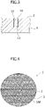
- the anodized film (AC/DC superposed electrolytic film) 20 formed by the AC/DC superposition electrolytic method grows in random directions with respect to the surface of the aluminum alloy material 4 and does not have orientation, the anodized film 20 grows while encapsulating silicon (not shown) contained in the aluminum alloy material 4 to be subjected to electrolytic treatment, while branching in random directions. Therefore, the anodized film 20 having a dense and smooth surface can be formed.
- an anodized film 23 is formed on the surface of the piston crown surface 2
- anodized films 21 are formed on the wall surfaces 11 of the recess 10
- an anodized film 22 is formed on the bottom surface 12 of the recess 10.
- the anodized film 20 to be formed is composed of a penetrating film in which approximately half of the film thickness of the anodized film 20 is penetrated into the surface of the piston crown surface 2 and the wall surfaces 11 and bottom surface 12 of the recess 10, and a growth film in which the remaining half of the film thickness is grown from the surface of the piston crown surface 2 and the wall surfaces 11 and bottom surface 12 of the recess 10.
- the cells of the anodized film 20 grow in random directions with respect to the surface of the aluminum alloy material 4, as described above.
- the anodizing treatment on the piston crown surface 2 is continued, as illustrated in Figure 5(d) , the growth speed of an anodized film 24 in the opening 13 of the recess 10 becomes faster than the growth speeds of the anodized films 21 and 22 of the wall surfaces 11 and the bottom surface 12 of the recess 10.
- the hollow space 26 can be generated inside the recess 10.
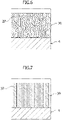
- the DC electrolytic method is a method of carrying out anodizing treatment by applying a certain level of DC voltage to the aluminum alloy material to be subjected to electrolytic treatment.
- an anodized film (DC electrolytic film) 30 formed by the DC electrolytic method grows in the direction perpendicular to the surface of the aluminum alloy material 4.
- the growth of the anodized film 30 is inhibited by the silicon (not shown) contained in the aluminum alloy material to be subjected to electrolytic treatment. Therefore, the roughness of the surface of the DC electrolytic film 30 is greater than that of the AC/DC superposed electrolytic film 20.
- the hollow spaces 26 are each formed inside the plurality of recesses 10 of the piston crown surface 2.
- the shape of the hollow spaces 26 depends on the shape of the recess 10.
- the plurality of hollow spaces 26 extend radially so as to widen from the center of the piston crown surface 2 toward the outer peripheral portion 3. Since the hollow spaces 26 are present inside the recesses 10 in the anodized film 20 of the present embodiment, the thermal conductivity and the volume specific heat capacity can be lowered.
- the hollow spaces 26 are formed in the aluminum alloy material 4, the anodized film 20 has excellent durability. Also, since the pores (not shown) themselves in the anodized film 20 are not sealed, heat retention can be suppressed even during a continuous run of the internal combustion engine.
- the hollow spaces 26 extend radially so as to widen from the center of the piston crown surface 2 toward the outer peripheral portion 3, and this means that an area ratio of the hollow spaces to the piston crown surface 2 is configured to gradually increase from the center of the piston crown surface 2 toward the outer peripheral portion 3.
- the lower the volume specific heat capacity the easier it is for the piston to become warm and cool down, and the less heat is trapped.
- the surface temperature easily changes according to the changes in gas temperature in the combustion chamber. Therefore, as the area ratio of the hollow spaces 26 to the piston crown surface 2 increases from the center of the piston crown surface 2 toward the outer peripheral portion 3, the lower thermal conductivity and the lower volume specific heat capacity are obtained. Consequently, the heat easily escapes from the center of the piston crown surface 2 toward the outer peripheral portion 3, effectively suppressing heat retention even at high rotation speeds and high loads.
- the fuel sticks to and adheres to the piston crown surface 2 (carbon deposit accumulate), then it may cause an occurrence of a malfunction of the internal combustion engine.
- the fuel even if the fuel adheres to the piston crown surface 2, the fuel can be caused to penetrate into the hollow spaces 26 through the pores of the anodized film 20 and adhere to the hollow spaces 26.
- the thermal load occurring at the start of the internal combustion engine causes the piston body 1 and the anodized film 20 to expand, and the difference in heat expansion coefficient between the aluminum alloy and the anodized film, which are the materials of the piston body 1, creates a difference between the degree of expansion and the degree of contraction.
- the repetition of expansion and contraction causes the adhered matter of the hollow spaces 26 to peel off, and since the hollow spaces 26 extend to the outer peripheral portion 3, the adhered matter can be discharged through the hollow spaces 26.
- a planarly circular recess 10A may be formed on the surface of the piston crown surface 2 of the piston body 1 to form a planarly circular hollow space inside the recess 10A.
- Figure 4 illustrates the recess having a planarly circular shape
- the shape is not limited thereto and for example, may be a polygonal shape such as a square shape or a shape such as an oval shape.
- recesses of the same size are evenly arranged on the piston crown surface 2, but the arrangement is not limited to such pattern, and the size of the recesses can be made to increase from the center of the piston crown surface 2 toward the outer peripheral portion 3, or the number of recesses can be increased so that the area ratio of the hollow spaces to the piston crown surface 2 can be gradually increased from the center of the piston crown surface 2 toward the outer peripheral portion 3, thereby allowing achieving the effect of suppressing heat retention even at high rotation speeds and high loads as described above.
- the film thickness of the anodized film 20 of the present embodiment is preferably, for example, 40 ⁇ m or more, and more preferably 50 ⁇ m or more, in order to enhance the heat shielding effect of the surface of the piston crown surface 2.
- the upper limit of the film thickness is, for example, preferably 100 ⁇ m or less, and more preferably 80 ⁇ m or less, in order to prevent heat retention (knocking resistance).
- the anodizing treatment step is carried out immediately after the laser irradiation step
- the present invention is not limited thereto, and for example, the method for manufacturing a piston for an internal combustion engine of the present invention may further include, as another embodiment, a masking application step prior to the anodizing treatment step, to apply a masking agent in the recess formed on the piston crown surface, and a masking removal step after the anodizing treatment step, to remove the masking agent applied to the recess.
- the method for manufacturing a piston for an internal combustion engine according to the present invention may include an aluminum alloy remelting step prior to the anodizing treatment step, to remelt the aluminum alloy in the recess formed on the piston crown surface.
- an aluminum alloy remelting step prior to the anodizing treatment step, to remelt the aluminum alloy in the recess formed on the piston crown surface.
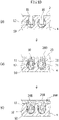
- the masking application step is carried out prior to the anodizing treatment step.
- a masking agent 40 is applied to the recess 10 of the piston crown surface 2.
- an anodized film 20A is formed on the surface of the piston crown surface 2 and the portions of the wall surfaces 11 of the recess 10 that are not covered with the masking agent 40 (i.e., the portions on the opening 13 side from an exposed surface 41 of the masking agent 40).
- the masking agent 40 for example, the one used in the production of a semiconductor can be used, and specific examples thereof include a photosensitive material called a photoresist. Furthermore, the masking agent can be applied to the inside of the recess 10 by using a photolithography technique or the like used in the production of a semiconductor.
- the opening 13 of the recess 10 is also closed with an anodized film 25A, as illustrated in Figure 9(b) .
- a hollow space 26A can be generated inside the recess 10.
- the anodizing treatment 20A since the anodizing treatment 20A has the hollow space 26A inside the recess 10 of the piston crown surface 2, the anodized film having low thermal conductivity and volume specific heat capacity, excellent durability, and the ability to suppress heat retention can be achieved.
- the masking agent 40 can be removed from the recess 10 by dissolving the masking agent 40 with a masking remover used in the production of a semiconductor or by firing the masking agent 40 by heating.
- the masking removal step does not have to be carried out, in which case the internal combustion engine piston having the masking agent 40 remaining in the recess 10 is mounted into the internal combustion engine, and thereafter the masking agent 40 is burned off by heat by starting the internal combustion engine, thereby generating the hollow space.
- the electrolytic method adopted in the anodizing treatment step is not limited to the AC/DC superposition electrolytic method; the hollow space 26A can be formed even by the DC electrolytic method.
- the anodized film 20A is formed by oxidizing the aluminum alloy material 4 as described above, the height of the anodized film 20A at the exposed surface 41 of the masking agent 40 becomes lowered significantly by the DC electrolytic method for growing the anodized film in the direction perpendicular to the surface of the aluminum alloy material 4. For this reason, the AC/DC superposition electrolytic method is preferred.
- the piston crown surface 2 needs to be smooth, and the lower the surface roughness of the anodized film 20A, the better the flow in the combustion chamber, resulting in less fuel adhering to the piston, improved fuel efficiency, and reduced gas exhaust.
- the AC/DC superposition electrolytic method is preferable in terms of obtaining an anodized film with a smooth surface that grows in random directions with respect to the surface of the aluminum alloy material 4.
- the aluminum alloy remelting step is carried out prior to the anodizing treatment step, to remelt the aluminum alloy on the lower portions of the wall surfaces 11 and the bottom surface 12 in the recess 10 of the piston crown surface 2.
- An aluminum alloy remelted portion 50 has a finer structure (silicon particle size) than the part that is not remelted. Therefore, as illustrated in Figure 10(b) , in the anodizing treatment step, the growth speed of the anodized film 20B can be made slower in the aluminum alloy remelted portion 50 than in the part that is not remelted.
- the opening 13 of the recess 10 can be closed with an anodized film 25B, and a hollow space 26B can be generated inside the recess 10. Therefore, since the anodizing treatment 20B has the hollow space 26B inside the recess 10 of the piston crown surface 2, the anodized film having low thermal conductivity and volume specific heat capacity, excellent durability, and the ability to suppress heat retention can be achieved.
- the hollow spaces 26 can be formed more easily by the synergistic effect with the anodizing treatment by the above-mentioned AC/DC superposition electrolytic method.
- the method for remelting the aluminum alloy include a method of re-irradiating the recess 10 of the piston crown surface 2 with laser light, an arc treatment, and an ion beam irradiation and the like.
- the structure (silicon particle size) of the aluminum alloy remelted portion 50 can be made finer than that of the part that is not melted, by making the laser output greater than the irradiation of the laser light for forming the recess, and the growth speed of the anodized film 20B can be made slower.
Landscapes
- Engineering & Computer Science (AREA)
- Chemical & Material Sciences (AREA)
- Chemical Kinetics & Catalysis (AREA)
- Electrochemistry (AREA)
- Materials Engineering (AREA)
- Metallurgy (AREA)
- Organic Chemistry (AREA)
- Combustion & Propulsion (AREA)
- Mechanical Engineering (AREA)
- General Engineering & Computer Science (AREA)
- Pistons, Piston Rings, And Cylinders (AREA)
Applications Claiming Priority (1)
| Application Number | Priority Date | Filing Date | Title |
|---|---|---|---|
| JP2021105737A JP7716649B2 (ja) | 2021-06-25 | 2021-06-25 | 内燃機関用ピストン及びその製造方法 |
Publications (2)
| Publication Number | Publication Date |
|---|---|
| EP4108902A1 true EP4108902A1 (de) | 2022-12-28 |
| EP4108902B1 EP4108902B1 (de) | 2024-02-14 |
Family
ID=80446197
Family Applications (1)
| Application Number | Title | Priority Date | Filing Date |
|---|---|---|---|
| EP22157853.7A Active EP4108902B1 (de) | 2021-06-25 | 2022-02-21 | Kolben für einen verbrennungsmotor und verfahren zur herstellung davon |
Country Status (2)
| Country | Link |
|---|---|
| EP (1) | EP4108902B1 (de) |
| JP (1) | JP7716649B2 (de) |
Citations (4)
| Publication number | Priority date | Publication date | Assignee | Title |
|---|---|---|---|---|
| JPS6075462U (ja) * | 1983-10-26 | 1985-05-27 | 日産ディーゼル工業株式会社 | アルミ合金材 |
| JP2015031226A (ja) | 2013-08-05 | 2015-02-16 | トヨタ自動車株式会社 | 内燃機関とその製造方法 |
| US20160138179A1 (en) * | 2014-03-27 | 2016-05-19 | Suzuki Motor Corporation | Anodizing treatment method and structure of internal combustion engine |
| JP2017122271A (ja) * | 2016-01-08 | 2017-07-13 | アイシン精機株式会社 | 陽極酸化皮膜生成方法およびアルミニウム成形品 |
Family Cites Families (6)
| Publication number | Priority date | Publication date | Assignee | Title |
|---|---|---|---|---|
| WO2001034408A1 (en) * | 1999-11-11 | 2001-05-17 | Koninklijke Philips Electronics N.V. | Marking of an anodized layer of an aluminium object |
| JP5707826B2 (ja) * | 2010-09-30 | 2015-04-30 | マツダ株式会社 | アルミ合金製品の断熱構造 |
| JP6369748B2 (ja) * | 2014-04-23 | 2018-08-08 | スズキ株式会社 | アルミニウム部材の表面被覆方法及び表面被覆アルミニウム部材並びに内燃機関用ピストン |
| JP6557176B2 (ja) * | 2016-05-30 | 2019-08-07 | 株式会社豊田中央研究所 | 内燃機関用ピストンおよびその製造方法 |
| JP2018090897A (ja) * | 2016-12-02 | 2018-06-14 | アイシン精機株式会社 | 陽極酸化皮膜の製造方法及び陽極酸化皮膜 |
| JP2020056352A (ja) * | 2018-10-02 | 2020-04-09 | 株式会社豊田中央研究所 | 内燃機関用部材およびその製造方法 |
-
2021
- 2021-06-25 JP JP2021105737A patent/JP7716649B2/ja active Active
-
2022
- 2022-02-21 EP EP22157853.7A patent/EP4108902B1/de active Active
Patent Citations (4)
| Publication number | Priority date | Publication date | Assignee | Title |
|---|---|---|---|---|
| JPS6075462U (ja) * | 1983-10-26 | 1985-05-27 | 日産ディーゼル工業株式会社 | アルミ合金材 |
| JP2015031226A (ja) | 2013-08-05 | 2015-02-16 | トヨタ自動車株式会社 | 内燃機関とその製造方法 |
| US20160138179A1 (en) * | 2014-03-27 | 2016-05-19 | Suzuki Motor Corporation | Anodizing treatment method and structure of internal combustion engine |
| JP2017122271A (ja) * | 2016-01-08 | 2017-07-13 | アイシン精機株式会社 | 陽極酸化皮膜生成方法およびアルミニウム成形品 |
Also Published As
| Publication number | Publication date |
|---|---|
| JP7716649B2 (ja) | 2025-08-01 |
| EP4108902B1 (de) | 2024-02-14 |
| JP2023004190A (ja) | 2023-01-17 |
Similar Documents
| Publication | Publication Date | Title |
|---|---|---|
| CN103080386B (zh) | 内燃发动机和制造内燃发动机的方法 | |
| US20120042859A1 (en) | Engine combustion chamber structure and manufacturing method thereof | |
| JP5607582B2 (ja) | エンジンバルブの製造方法 | |
| JP6814406B2 (ja) | アルミニウム部材の表面構造及びその製造方法 | |
| JP6927057B2 (ja) | 圧縮自着火式内燃機関 | |
| JP6557176B2 (ja) | 内燃機関用ピストンおよびその製造方法 | |
| EP3180462B1 (de) | Verfahren zur herstellung eines kolbens für einen verbrennungsmotor | |
| EP4108902B1 (de) | Kolben für einen verbrennungsmotor und verfahren zur herstellung davon | |
| JP6070631B2 (ja) | 内燃機関のピストン | |
| EP3591198B1 (de) | Verbrennungsmotor | |
| JP2012122445A (ja) | 内燃機関のピストン構造 | |
| JP6187545B2 (ja) | 内燃機関のピストン、該ピストンを備える内燃機関および該ピストンの製造方法 | |
| JP2010203334A (ja) | 内燃機関のピストン | |
| JP2016006211A (ja) | アルミ複合材の遮熱コーティング方法及びその構造並びにピストン | |
| EP4137612A1 (de) | Kolben für einen verbrennungsmotor und verfahren zur herstellung davon | |
| EP3851657B1 (de) | Herstellungsverfahren für kolben einer brennkraftmaschine | |
| JP7578902B2 (ja) | 内燃機関用ピストン及びその製造方法 | |
| JP2020056352A (ja) | 内燃機関用部材およびその製造方法 | |
| CN110983408B (zh) | 利用陶瓷颗粒化学自烧结微弧氧化技术制备纳米陶瓷涂层的方法 | |
| JP2019060319A (ja) | 遮熱膜を有するエンジン構成部材及び該エンジン構成部材の製造方法。 |
Legal Events
| Date | Code | Title | Description |
|---|---|---|---|
| PUAI | Public reference made under article 153(3) epc to a published international application that has entered the european phase |
Free format text: ORIGINAL CODE: 0009012 |
|
| STAA | Information on the status of an ep patent application or granted ep patent |
Free format text: STATUS: REQUEST FOR EXAMINATION WAS MADE |
|
| 17P | Request for examination filed |
Effective date: 20220221 |
|
| AK | Designated contracting states |
Kind code of ref document: A1 Designated state(s): AL AT BE BG CH CY CZ DE DK EE ES FI FR GB GR HR HU IE IS IT LI LT LU LV MC MK MT NL NO PL PT RO RS SE SI SK SM TR |
|
| GRAP | Despatch of communication of intention to grant a patent |
Free format text: ORIGINAL CODE: EPIDOSNIGR1 |
|
| STAA | Information on the status of an ep patent application or granted ep patent |
Free format text: STATUS: GRANT OF PATENT IS INTENDED |
|
| INTG | Intention to grant announced |
Effective date: 20231109 |
|
| GRAS | Grant fee paid |
Free format text: ORIGINAL CODE: EPIDOSNIGR3 |
|
| GRAA | (expected) grant |
Free format text: ORIGINAL CODE: 0009210 |
|
| STAA | Information on the status of an ep patent application or granted ep patent |
Free format text: STATUS: THE PATENT HAS BEEN GRANTED |
|
| AK | Designated contracting states |
Kind code of ref document: B1 Designated state(s): AL AT BE BG CH CY CZ DE DK EE ES FI FR GB GR HR HU IE IS IT LI LT LU LV MC MK MT NL NO PL PT RO RS SE SI SK SM TR |
|
| REG | Reference to a national code |
Ref country code: GB Ref legal event code: FG4D |
|
| REG | Reference to a national code |
Ref country code: CH Ref legal event code: EP |
|
| REG | Reference to a national code |
Ref country code: DE Ref legal event code: R096 Ref document number: 602022001886 Country of ref document: DE |
|
| REG | Reference to a national code |
Ref country code: IE Ref legal event code: FG4D |
|
| REG | Reference to a national code |
Ref country code: LT Ref legal event code: MG9D |
|
| REG | Reference to a national code |
Ref country code: NL Ref legal event code: MP Effective date: 20240214 |
|
| PG25 | Lapsed in a contracting state [announced via postgrant information from national office to epo] |
Ref country code: IS Free format text: LAPSE BECAUSE OF FAILURE TO SUBMIT A TRANSLATION OF THE DESCRIPTION OR TO PAY THE FEE WITHIN THE PRESCRIBED TIME-LIMIT Effective date: 20240614 |
|
| PG25 | Lapsed in a contracting state [announced via postgrant information from national office to epo] |
Ref country code: LT Free format text: LAPSE BECAUSE OF FAILURE TO SUBMIT A TRANSLATION OF THE DESCRIPTION OR TO PAY THE FEE WITHIN THE PRESCRIBED TIME-LIMIT Effective date: 20240214 |
|
| PG25 | Lapsed in a contracting state [announced via postgrant information from national office to epo] |
Ref country code: GR Free format text: LAPSE BECAUSE OF FAILURE TO SUBMIT A TRANSLATION OF THE DESCRIPTION OR TO PAY THE FEE WITHIN THE PRESCRIBED TIME-LIMIT Effective date: 20240515 |
|
| REG | Reference to a national code |
Ref country code: AT Ref legal event code: MK05 Ref document number: 1657199 Country of ref document: AT Kind code of ref document: T Effective date: 20240214 |
|
| PG25 | Lapsed in a contracting state [announced via postgrant information from national office to epo] |
Ref country code: HR Free format text: LAPSE BECAUSE OF FAILURE TO SUBMIT A TRANSLATION OF THE DESCRIPTION OR TO PAY THE FEE WITHIN THE PRESCRIBED TIME-LIMIT Effective date: 20240214 Ref country code: RS Free format text: LAPSE BECAUSE OF FAILURE TO SUBMIT A TRANSLATION OF THE DESCRIPTION OR TO PAY THE FEE WITHIN THE PRESCRIBED TIME-LIMIT Effective date: 20240514 Ref country code: NL Free format text: LAPSE BECAUSE OF FAILURE TO SUBMIT A TRANSLATION OF THE DESCRIPTION OR TO PAY THE FEE WITHIN THE PRESCRIBED TIME-LIMIT Effective date: 20240214 |
|
| PG25 | Lapsed in a contracting state [announced via postgrant information from national office to epo] |
Ref country code: ES Free format text: LAPSE BECAUSE OF FAILURE TO SUBMIT A TRANSLATION OF THE DESCRIPTION OR TO PAY THE FEE WITHIN THE PRESCRIBED TIME-LIMIT Effective date: 20240214 |
|
| PG25 | Lapsed in a contracting state [announced via postgrant information from national office to epo] |
Ref country code: AT Free format text: LAPSE BECAUSE OF FAILURE TO SUBMIT A TRANSLATION OF THE DESCRIPTION OR TO PAY THE FEE WITHIN THE PRESCRIBED TIME-LIMIT Effective date: 20240214 |
|
| PG25 | Lapsed in a contracting state [announced via postgrant information from national office to epo] |
Ref country code: RS Free format text: LAPSE BECAUSE OF FAILURE TO SUBMIT A TRANSLATION OF THE DESCRIPTION OR TO PAY THE FEE WITHIN THE PRESCRIBED TIME-LIMIT Effective date: 20240514 Ref country code: NO Free format text: LAPSE BECAUSE OF FAILURE TO SUBMIT A TRANSLATION OF THE DESCRIPTION OR TO PAY THE FEE WITHIN THE PRESCRIBED TIME-LIMIT Effective date: 20240514 Ref country code: NL Free format text: LAPSE BECAUSE OF FAILURE TO SUBMIT A TRANSLATION OF THE DESCRIPTION OR TO PAY THE FEE WITHIN THE PRESCRIBED TIME-LIMIT Effective date: 20240214 Ref country code: LT Free format text: LAPSE BECAUSE OF FAILURE TO SUBMIT A TRANSLATION OF THE DESCRIPTION OR TO PAY THE FEE WITHIN THE PRESCRIBED TIME-LIMIT Effective date: 20240214 Ref country code: IS Free format text: LAPSE BECAUSE OF FAILURE TO SUBMIT A TRANSLATION OF THE DESCRIPTION OR TO PAY THE FEE WITHIN THE PRESCRIBED TIME-LIMIT Effective date: 20240614 Ref country code: HR Free format text: LAPSE BECAUSE OF FAILURE TO SUBMIT A TRANSLATION OF THE DESCRIPTION OR TO PAY THE FEE WITHIN THE PRESCRIBED TIME-LIMIT Effective date: 20240214 Ref country code: GR Free format text: LAPSE BECAUSE OF FAILURE TO SUBMIT A TRANSLATION OF THE DESCRIPTION OR TO PAY THE FEE WITHIN THE PRESCRIBED TIME-LIMIT Effective date: 20240515 Ref country code: FI Free format text: LAPSE BECAUSE OF FAILURE TO SUBMIT A TRANSLATION OF THE DESCRIPTION OR TO PAY THE FEE WITHIN THE PRESCRIBED TIME-LIMIT Effective date: 20240214 Ref country code: ES Free format text: LAPSE BECAUSE OF FAILURE TO SUBMIT A TRANSLATION OF THE DESCRIPTION OR TO PAY THE FEE WITHIN THE PRESCRIBED TIME-LIMIT Effective date: 20240214 Ref country code: BG Free format text: LAPSE BECAUSE OF FAILURE TO SUBMIT A TRANSLATION OF THE DESCRIPTION OR TO PAY THE FEE WITHIN THE PRESCRIBED TIME-LIMIT Effective date: 20240214 Ref country code: AT Free format text: LAPSE BECAUSE OF FAILURE TO SUBMIT A TRANSLATION OF THE DESCRIPTION OR TO PAY THE FEE WITHIN THE PRESCRIBED TIME-LIMIT Effective date: 20240214 |
|
| PG25 | Lapsed in a contracting state [announced via postgrant information from national office to epo] |
Ref country code: PT Free format text: LAPSE BECAUSE OF FAILURE TO SUBMIT A TRANSLATION OF THE DESCRIPTION OR TO PAY THE FEE WITHIN THE PRESCRIBED TIME-LIMIT Effective date: 20240614 Ref country code: PL Free format text: LAPSE BECAUSE OF FAILURE TO SUBMIT A TRANSLATION OF THE DESCRIPTION OR TO PAY THE FEE WITHIN THE PRESCRIBED TIME-LIMIT Effective date: 20240214 |
|
| PG25 | Lapsed in a contracting state [announced via postgrant information from national office to epo] |
Ref country code: SE Free format text: LAPSE BECAUSE OF FAILURE TO SUBMIT A TRANSLATION OF THE DESCRIPTION OR TO PAY THE FEE WITHIN THE PRESCRIBED TIME-LIMIT Effective date: 20240214 Ref country code: PT Free format text: LAPSE BECAUSE OF FAILURE TO SUBMIT A TRANSLATION OF THE DESCRIPTION OR TO PAY THE FEE WITHIN THE PRESCRIBED TIME-LIMIT Effective date: 20240614 Ref country code: PL Free format text: LAPSE BECAUSE OF FAILURE TO SUBMIT A TRANSLATION OF THE DESCRIPTION OR TO PAY THE FEE WITHIN THE PRESCRIBED TIME-LIMIT Effective date: 20240214 Ref country code: LV Free format text: LAPSE BECAUSE OF FAILURE TO SUBMIT A TRANSLATION OF THE DESCRIPTION OR TO PAY THE FEE WITHIN THE PRESCRIBED TIME-LIMIT Effective date: 20240214 |
|
| PG25 | Lapsed in a contracting state [announced via postgrant information from national office to epo] |
Ref country code: DK Free format text: LAPSE BECAUSE OF FAILURE TO SUBMIT A TRANSLATION OF THE DESCRIPTION OR TO PAY THE FEE WITHIN THE PRESCRIBED TIME-LIMIT Effective date: 20240214 |
|
| PG25 | Lapsed in a contracting state [announced via postgrant information from national office to epo] |
Ref country code: SM Free format text: LAPSE BECAUSE OF FAILURE TO SUBMIT A TRANSLATION OF THE DESCRIPTION OR TO PAY THE FEE WITHIN THE PRESCRIBED TIME-LIMIT Effective date: 20240214 |
|
| PG25 | Lapsed in a contracting state [announced via postgrant information from national office to epo] |
Ref country code: LU Free format text: LAPSE BECAUSE OF NON-PAYMENT OF DUE FEES Effective date: 20240221 |
|
| PG25 | Lapsed in a contracting state [announced via postgrant information from national office to epo] |
Ref country code: EE Free format text: LAPSE BECAUSE OF FAILURE TO SUBMIT A TRANSLATION OF THE DESCRIPTION OR TO PAY THE FEE WITHIN THE PRESCRIBED TIME-LIMIT Effective date: 20240214 Ref country code: CZ Free format text: LAPSE BECAUSE OF FAILURE TO SUBMIT A TRANSLATION OF THE DESCRIPTION OR TO PAY THE FEE WITHIN THE PRESCRIBED TIME-LIMIT Effective date: 20240214 |
|
| PG25 | Lapsed in a contracting state [announced via postgrant information from national office to epo] |
Ref country code: SK Free format text: LAPSE BECAUSE OF FAILURE TO SUBMIT A TRANSLATION OF THE DESCRIPTION OR TO PAY THE FEE WITHIN THE PRESCRIBED TIME-LIMIT Effective date: 20240214 |
|
| PG25 | Lapsed in a contracting state [announced via postgrant information from national office to epo] |
Ref country code: SM Free format text: LAPSE BECAUSE OF FAILURE TO SUBMIT A TRANSLATION OF THE DESCRIPTION OR TO PAY THE FEE WITHIN THE PRESCRIBED TIME-LIMIT Effective date: 20240214 Ref country code: SK Free format text: LAPSE BECAUSE OF FAILURE TO SUBMIT A TRANSLATION OF THE DESCRIPTION OR TO PAY THE FEE WITHIN THE PRESCRIBED TIME-LIMIT Effective date: 20240214 Ref country code: RO Free format text: LAPSE BECAUSE OF FAILURE TO SUBMIT A TRANSLATION OF THE DESCRIPTION OR TO PAY THE FEE WITHIN THE PRESCRIBED TIME-LIMIT Effective date: 20240214 Ref country code: LU Free format text: LAPSE BECAUSE OF NON-PAYMENT OF DUE FEES Effective date: 20240221 Ref country code: EE Free format text: LAPSE BECAUSE OF FAILURE TO SUBMIT A TRANSLATION OF THE DESCRIPTION OR TO PAY THE FEE WITHIN THE PRESCRIBED TIME-LIMIT Effective date: 20240214 Ref country code: DK Free format text: LAPSE BECAUSE OF FAILURE TO SUBMIT A TRANSLATION OF THE DESCRIPTION OR TO PAY THE FEE WITHIN THE PRESCRIBED TIME-LIMIT Effective date: 20240214 Ref country code: CZ Free format text: LAPSE BECAUSE OF FAILURE TO SUBMIT A TRANSLATION OF THE DESCRIPTION OR TO PAY THE FEE WITHIN THE PRESCRIBED TIME-LIMIT Effective date: 20240214 |
|
| REG | Reference to a national code |
Ref country code: DE Ref legal event code: R097 Ref document number: 602022001886 Country of ref document: DE |
|
| PG25 | Lapsed in a contracting state [announced via postgrant information from national office to epo] |
Ref country code: MC Free format text: LAPSE BECAUSE OF FAILURE TO SUBMIT A TRANSLATION OF THE DESCRIPTION OR TO PAY THE FEE WITHIN THE PRESCRIBED TIME-LIMIT Effective date: 20240214 |
|
| PG25 | Lapsed in a contracting state [announced via postgrant information from national office to epo] |
Ref country code: MC Free format text: LAPSE BECAUSE OF FAILURE TO SUBMIT A TRANSLATION OF THE DESCRIPTION OR TO PAY THE FEE WITHIN THE PRESCRIBED TIME-LIMIT Effective date: 20240214 |
|
| PG25 | Lapsed in a contracting state [announced via postgrant information from national office to epo] |
Ref country code: IT Free format text: LAPSE BECAUSE OF FAILURE TO SUBMIT A TRANSLATION OF THE DESCRIPTION OR TO PAY THE FEE WITHIN THE PRESCRIBED TIME-LIMIT Effective date: 20240214 |
|
| REG | Reference to a national code |
Ref country code: BE Ref legal event code: MM Effective date: 20240229 |
|
| PLBE | No opposition filed within time limit |
Free format text: ORIGINAL CODE: 0009261 |
|
| STAA | Information on the status of an ep patent application or granted ep patent |
Free format text: STATUS: NO OPPOSITION FILED WITHIN TIME LIMIT |
|
| PG25 | Lapsed in a contracting state [announced via postgrant information from national office to epo] |
Ref country code: IT Free format text: LAPSE BECAUSE OF FAILURE TO SUBMIT A TRANSLATION OF THE DESCRIPTION OR TO PAY THE FEE WITHIN THE PRESCRIBED TIME-LIMIT Effective date: 20240214 |
|
| PG25 | Lapsed in a contracting state [announced via postgrant information from national office to epo] |
Ref country code: BE Free format text: LAPSE BECAUSE OF NON-PAYMENT OF DUE FEES Effective date: 20240229 |
|
| 26N | No opposition filed |
Effective date: 20241115 |
|
| PG25 | Lapsed in a contracting state [announced via postgrant information from national office to epo] |
Ref country code: IE Free format text: LAPSE BECAUSE OF NON-PAYMENT OF DUE FEES Effective date: 20240221 |
|
| PG25 | Lapsed in a contracting state [announced via postgrant information from national office to epo] |
Ref country code: IE Free format text: LAPSE BECAUSE OF NON-PAYMENT OF DUE FEES Effective date: 20240221 Ref country code: BE Free format text: LAPSE BECAUSE OF NON-PAYMENT OF DUE FEES Effective date: 20240229 |
|
| PG25 | Lapsed in a contracting state [announced via postgrant information from national office to epo] |
Ref country code: SI Free format text: LAPSE BECAUSE OF FAILURE TO SUBMIT A TRANSLATION OF THE DESCRIPTION OR TO PAY THE FEE WITHIN THE PRESCRIBED TIME-LIMIT Effective date: 20240214 |
|
| PG25 | Lapsed in a contracting state [announced via postgrant information from national office to epo] |
Ref country code: CY Free format text: LAPSE BECAUSE OF FAILURE TO SUBMIT A TRANSLATION OF THE DESCRIPTION OR TO PAY THE FEE WITHIN THE PRESCRIBED TIME-LIMIT; INVALID AB INITIO Effective date: 20220221 |
|
| REG | Reference to a national code |
Ref country code: CH Ref legal event code: PL |
|
| PG25 | Lapsed in a contracting state [announced via postgrant information from national office to epo] |
Ref country code: CH Free format text: LAPSE BECAUSE OF NON-PAYMENT OF DUE FEES Effective date: 20250228 |
|
| PG25 | Lapsed in a contracting state [announced via postgrant information from national office to epo] |
Ref country code: TR Free format text: LAPSE BECAUSE OF FAILURE TO SUBMIT A TRANSLATION OF THE DESCRIPTION OR TO PAY THE FEE WITHIN THE PRESCRIBED TIME-LIMIT Effective date: 20240214 |
|
| PGFP | Annual fee paid to national office [announced via postgrant information from national office to epo] |
Ref country code: FR Payment date: 20251231 Year of fee payment: 5 |
|
| PGFP | Annual fee paid to national office [announced via postgrant information from national office to epo] |
Ref country code: DE Payment date: 20251230 Year of fee payment: 5 |