EP4104988A1 - Machining apparatus - Google Patents
Machining apparatus Download PDFInfo
- Publication number
- EP4104988A1 EP4104988A1 EP21753070.8A EP21753070A EP4104988A1 EP 4104988 A1 EP4104988 A1 EP 4104988A1 EP 21753070 A EP21753070 A EP 21753070A EP 4104988 A1 EP4104988 A1 EP 4104988A1
- Authority
- EP
- European Patent Office
- Prior art keywords
- machining
- cutting
- workpiece
- tables
- substrate
- Prior art date
- Legal status (The legal status is an assumption and is not a legal conclusion. Google has not performed a legal analysis and makes no representation as to the accuracy of the status listed.)
- Pending
Links
Images




Classifications
-
- B—PERFORMING OPERATIONS; TRANSPORTING
- B23—MACHINE TOOLS; METAL-WORKING NOT OTHERWISE PROVIDED FOR
- B23D—PLANING; SLOTTING; SHEARING; BROACHING; SAWING; FILING; SCRAPING; LIKE OPERATIONS FOR WORKING METAL BY REMOVING MATERIAL, NOT OTHERWISE PROVIDED FOR
- B23D45/00—Sawing machines or sawing devices with circular saw blades or with friction saw discs
- B23D45/02—Sawing machines or sawing devices with circular saw blades or with friction saw discs with a circular saw blade or the stock mounted on a carriage
- B23D45/021—Sawing machines or sawing devices with circular saw blades or with friction saw discs with a circular saw blade or the stock mounted on a carriage with the saw blade mounted on a carriage
-
- B—PERFORMING OPERATIONS; TRANSPORTING
- B26—HAND CUTTING TOOLS; CUTTING; SEVERING
- B26D—CUTTING; DETAILS COMMON TO MACHINES FOR PERFORATING, PUNCHING, CUTTING-OUT, STAMPING-OUT OR SEVERING
- B26D1/00—Cutting through work characterised by the nature or movement of the cutting member or particular materials not otherwise provided for; Apparatus or machines therefor; Cutting members therefor
- B26D1/56—Cutting through work characterised by the nature or movement of the cutting member or particular materials not otherwise provided for; Apparatus or machines therefor; Cutting members therefor involving a cutting member which travels with the work otherwise than in the direction of the cut, i.e. flying cutter
- B26D1/60—Cutting through work characterised by the nature or movement of the cutting member or particular materials not otherwise provided for; Apparatus or machines therefor; Cutting members therefor involving a cutting member which travels with the work otherwise than in the direction of the cut, i.e. flying cutter and is mounted on a movable carriage
-
- B—PERFORMING OPERATIONS; TRANSPORTING
- B23—MACHINE TOOLS; METAL-WORKING NOT OTHERWISE PROVIDED FOR
- B23Q—DETAILS, COMPONENTS, OR ACCESSORIES FOR MACHINE TOOLS, e.g. ARRANGEMENTS FOR COPYING OR CONTROLLING; MACHINE TOOLS IN GENERAL CHARACTERISED BY THE CONSTRUCTION OF PARTICULAR DETAILS OR COMPONENTS; COMBINATIONS OR ASSOCIATIONS OF METAL-WORKING MACHINES, NOT DIRECTED TO A PARTICULAR RESULT
- B23Q1/00—Members which are comprised in the general build-up of a form of machine, particularly relatively large fixed members
- B23Q1/01—Frames, beds, pillars or like members; Arrangement of ways
- B23Q1/012—Portals
-
- B—PERFORMING OPERATIONS; TRANSPORTING
- B23—MACHINE TOOLS; METAL-WORKING NOT OTHERWISE PROVIDED FOR
- B23D—PLANING; SLOTTING; SHEARING; BROACHING; SAWING; FILING; SCRAPING; LIKE OPERATIONS FOR WORKING METAL BY REMOVING MATERIAL, NOT OTHERWISE PROVIDED FOR
- B23D45/00—Sawing machines or sawing devices with circular saw blades or with friction saw discs
- B23D45/02—Sawing machines or sawing devices with circular saw blades or with friction saw discs with a circular saw blade or the stock mounted on a carriage
- B23D45/021—Sawing machines or sawing devices with circular saw blades or with friction saw discs with a circular saw blade or the stock mounted on a carriage with the saw blade mounted on a carriage
- B23D45/027—Sawing machines or sawing devices with circular saw blades or with friction saw discs with a circular saw blade or the stock mounted on a carriage with the saw blade mounted on a carriage the saw carriage being mounted on a carriage, e.g. gantry-type sawing machines
-
- B—PERFORMING OPERATIONS; TRANSPORTING
- B23—MACHINE TOOLS; METAL-WORKING NOT OTHERWISE PROVIDED FOR
- B23Q—DETAILS, COMPONENTS, OR ACCESSORIES FOR MACHINE TOOLS, e.g. ARRANGEMENTS FOR COPYING OR CONTROLLING; MACHINE TOOLS IN GENERAL CHARACTERISED BY THE CONSTRUCTION OF PARTICULAR DETAILS OR COMPONENTS; COMBINATIONS OR ASSOCIATIONS OF METAL-WORKING MACHINES, NOT DIRECTED TO A PARTICULAR RESULT
- B23Q1/00—Members which are comprised in the general build-up of a form of machine, particularly relatively large fixed members
- B23Q1/01—Frames, beds, pillars or like members; Arrangement of ways
-
- B—PERFORMING OPERATIONS; TRANSPORTING
- B23—MACHINE TOOLS; METAL-WORKING NOT OTHERWISE PROVIDED FOR
- B23Q—DETAILS, COMPONENTS, OR ACCESSORIES FOR MACHINE TOOLS, e.g. ARRANGEMENTS FOR COPYING OR CONTROLLING; MACHINE TOOLS IN GENERAL CHARACTERISED BY THE CONSTRUCTION OF PARTICULAR DETAILS OR COMPONENTS; COMBINATIONS OR ASSOCIATIONS OF METAL-WORKING MACHINES, NOT DIRECTED TO A PARTICULAR RESULT
- B23Q1/00—Members which are comprised in the general build-up of a form of machine, particularly relatively large fixed members
- B23Q1/03—Stationary work or tool supports
-
- B—PERFORMING OPERATIONS; TRANSPORTING
- B23—MACHINE TOOLS; METAL-WORKING NOT OTHERWISE PROVIDED FOR
- B23Q—DETAILS, COMPONENTS, OR ACCESSORIES FOR MACHINE TOOLS, e.g. ARRANGEMENTS FOR COPYING OR CONTROLLING; MACHINE TOOLS IN GENERAL CHARACTERISED BY THE CONSTRUCTION OF PARTICULAR DETAILS OR COMPONENTS; COMBINATIONS OR ASSOCIATIONS OF METAL-WORKING MACHINES, NOT DIRECTED TO A PARTICULAR RESULT
- B23Q1/00—Members which are comprised in the general build-up of a form of machine, particularly relatively large fixed members
- B23Q1/25—Movable or adjustable work or tool supports
-
- B—PERFORMING OPERATIONS; TRANSPORTING
- B23—MACHINE TOOLS; METAL-WORKING NOT OTHERWISE PROVIDED FOR
- B23Q—DETAILS, COMPONENTS, OR ACCESSORIES FOR MACHINE TOOLS, e.g. ARRANGEMENTS FOR COPYING OR CONTROLLING; MACHINE TOOLS IN GENERAL CHARACTERISED BY THE CONSTRUCTION OF PARTICULAR DETAILS OR COMPONENTS; COMBINATIONS OR ASSOCIATIONS OF METAL-WORKING MACHINES, NOT DIRECTED TO A PARTICULAR RESULT
- B23Q1/00—Members which are comprised in the general build-up of a form of machine, particularly relatively large fixed members
- B23Q1/25—Movable or adjustable work or tool supports
- B23Q1/44—Movable or adjustable work or tool supports using particular mechanisms
- B23Q1/48—Movable or adjustable work or tool supports using particular mechanisms with sliding pairs and rotating pairs
-
- B—PERFORMING OPERATIONS; TRANSPORTING
- B23—MACHINE TOOLS; METAL-WORKING NOT OTHERWISE PROVIDED FOR
- B23Q—DETAILS, COMPONENTS, OR ACCESSORIES FOR MACHINE TOOLS, e.g. ARRANGEMENTS FOR COPYING OR CONTROLLING; MACHINE TOOLS IN GENERAL CHARACTERISED BY THE CONSTRUCTION OF PARTICULAR DETAILS OR COMPONENTS; COMBINATIONS OR ASSOCIATIONS OF METAL-WORKING MACHINES, NOT DIRECTED TO A PARTICULAR RESULT
- B23Q1/00—Members which are comprised in the general build-up of a form of machine, particularly relatively large fixed members
- B23Q1/25—Movable or adjustable work or tool supports
- B23Q1/44—Movable or adjustable work or tool supports using particular mechanisms
- B23Q1/56—Movable or adjustable work or tool supports using particular mechanisms with sliding pairs only, the sliding pairs being the first two elements of the mechanism
- B23Q1/60—Movable or adjustable work or tool supports using particular mechanisms with sliding pairs only, the sliding pairs being the first two elements of the mechanism two sliding pairs only, the sliding pairs being the first two elements of the mechanism
- B23Q1/62—Movable or adjustable work or tool supports using particular mechanisms with sliding pairs only, the sliding pairs being the first two elements of the mechanism two sliding pairs only, the sliding pairs being the first two elements of the mechanism with perpendicular axes, e.g. cross-slides
-
- B—PERFORMING OPERATIONS; TRANSPORTING
- B23—MACHINE TOOLS; METAL-WORKING NOT OTHERWISE PROVIDED FOR
- B23Q—DETAILS, COMPONENTS, OR ACCESSORIES FOR MACHINE TOOLS, e.g. ARRANGEMENTS FOR COPYING OR CONTROLLING; MACHINE TOOLS IN GENERAL CHARACTERISED BY THE CONSTRUCTION OF PARTICULAR DETAILS OR COMPONENTS; COMBINATIONS OR ASSOCIATIONS OF METAL-WORKING MACHINES, NOT DIRECTED TO A PARTICULAR RESULT
- B23Q39/00—Metal-working machines incorporating a plurality of sub-assemblies, each capable of performing a metal-working operation
- B23Q39/02—Metal-working machines incorporating a plurality of sub-assemblies, each capable of performing a metal-working operation the sub-assemblies being capable of being brought to act at a single operating station
- B23Q39/021—Metal-working machines incorporating a plurality of sub-assemblies, each capable of performing a metal-working operation the sub-assemblies being capable of being brought to act at a single operating station with a plurality of toolheads per workholder, whereby the toolhead is a main spindle, a multispindle, a revolver or the like
-
- B—PERFORMING OPERATIONS; TRANSPORTING
- B23—MACHINE TOOLS; METAL-WORKING NOT OTHERWISE PROVIDED FOR
- B23Q—DETAILS, COMPONENTS, OR ACCESSORIES FOR MACHINE TOOLS, e.g. ARRANGEMENTS FOR COPYING OR CONTROLLING; MACHINE TOOLS IN GENERAL CHARACTERISED BY THE CONSTRUCTION OF PARTICULAR DETAILS OR COMPONENTS; COMBINATIONS OR ASSOCIATIONS OF METAL-WORKING MACHINES, NOT DIRECTED TO A PARTICULAR RESULT
- B23Q39/00—Metal-working machines incorporating a plurality of sub-assemblies, each capable of performing a metal-working operation
- B23Q39/02—Metal-working machines incorporating a plurality of sub-assemblies, each capable of performing a metal-working operation the sub-assemblies being capable of being brought to act at a single operating station
- B23Q39/028—Metal-working machines incorporating a plurality of sub-assemblies, each capable of performing a metal-working operation the sub-assemblies being capable of being brought to act at a single operating station with a plurality of workholder per toolhead in operating position
-
- B—PERFORMING OPERATIONS; TRANSPORTING
- B26—HAND CUTTING TOOLS; CUTTING; SEVERING
- B26D—CUTTING; DETAILS COMMON TO MACHINES FOR PERFORATING, PUNCHING, CUTTING-OUT, STAMPING-OUT OR SEVERING
- B26D1/00—Cutting through work characterised by the nature or movement of the cutting member or particular materials not otherwise provided for; Apparatus or machines therefor; Cutting members therefor
- B26D1/01—Cutting through work characterised by the nature or movement of the cutting member or particular materials not otherwise provided for; Apparatus or machines therefor; Cutting members therefor involving a cutting member which does not travel with the work
- B26D1/12—Cutting through work characterised by the nature or movement of the cutting member or particular materials not otherwise provided for; Apparatus or machines therefor; Cutting members therefor involving a cutting member which does not travel with the work having a cutting member moving about an axis
- B26D1/14—Cutting through work characterised by the nature or movement of the cutting member or particular materials not otherwise provided for; Apparatus or machines therefor; Cutting members therefor involving a cutting member which does not travel with the work having a cutting member moving about an axis with a circular cutting member, e.g. disc cutter
- B26D1/157—Cutting through work characterised by the nature or movement of the cutting member or particular materials not otherwise provided for; Apparatus or machines therefor; Cutting members therefor involving a cutting member which does not travel with the work having a cutting member moving about an axis with a circular cutting member, e.g. disc cutter rotating about a movable axis
- B26D1/18—Cutting through work characterised by the nature or movement of the cutting member or particular materials not otherwise provided for; Apparatus or machines therefor; Cutting members therefor involving a cutting member which does not travel with the work having a cutting member moving about an axis with a circular cutting member, e.g. disc cutter rotating about a movable axis mounted on a movable carriage
-
- B—PERFORMING OPERATIONS; TRANSPORTING
- B26—HAND CUTTING TOOLS; CUTTING; SEVERING
- B26D—CUTTING; DETAILS COMMON TO MACHINES FOR PERFORATING, PUNCHING, CUTTING-OUT, STAMPING-OUT OR SEVERING
- B26D1/00—Cutting through work characterised by the nature or movement of the cutting member or particular materials not otherwise provided for; Apparatus or machines therefor; Cutting members therefor
- B26D1/01—Cutting through work characterised by the nature or movement of the cutting member or particular materials not otherwise provided for; Apparatus or machines therefor; Cutting members therefor involving a cutting member which does not travel with the work
- B26D1/12—Cutting through work characterised by the nature or movement of the cutting member or particular materials not otherwise provided for; Apparatus or machines therefor; Cutting members therefor involving a cutting member which does not travel with the work having a cutting member moving about an axis
- B26D1/14—Cutting through work characterised by the nature or movement of the cutting member or particular materials not otherwise provided for; Apparatus or machines therefor; Cutting members therefor involving a cutting member which does not travel with the work having a cutting member moving about an axis with a circular cutting member, e.g. disc cutter
- B26D1/157—Cutting through work characterised by the nature or movement of the cutting member or particular materials not otherwise provided for; Apparatus or machines therefor; Cutting members therefor involving a cutting member which does not travel with the work having a cutting member moving about an axis with a circular cutting member, e.g. disc cutter rotating about a movable axis
- B26D1/18—Cutting through work characterised by the nature or movement of the cutting member or particular materials not otherwise provided for; Apparatus or machines therefor; Cutting members therefor involving a cutting member which does not travel with the work having a cutting member moving about an axis with a circular cutting member, e.g. disc cutter rotating about a movable axis mounted on a movable carriage
- B26D1/185—Cutting through work characterised by the nature or movement of the cutting member or particular materials not otherwise provided for; Apparatus or machines therefor; Cutting members therefor involving a cutting member which does not travel with the work having a cutting member moving about an axis with a circular cutting member, e.g. disc cutter rotating about a movable axis mounted on a movable carriage for thin material, e.g. for sheets, strips or the like
-
- B—PERFORMING OPERATIONS; TRANSPORTING
- B26—HAND CUTTING TOOLS; CUTTING; SEVERING
- B26D—CUTTING; DETAILS COMMON TO MACHINES FOR PERFORATING, PUNCHING, CUTTING-OUT, STAMPING-OUT OR SEVERING
- B26D7/00—Details of apparatus for cutting, cutting-out, stamping-out, punching, perforating, or severing by means other than cutting
- B26D7/01—Means for holding or positioning work
- B26D7/018—Holding the work by suction
-
- B—PERFORMING OPERATIONS; TRANSPORTING
- B26—HAND CUTTING TOOLS; CUTTING; SEVERING
- B26D—CUTTING; DETAILS COMMON TO MACHINES FOR PERFORATING, PUNCHING, CUTTING-OUT, STAMPING-OUT OR SEVERING
- B26D7/00—Details of apparatus for cutting, cutting-out, stamping-out, punching, perforating, or severing by means other than cutting
- B26D7/01—Means for holding or positioning work
- B26D7/02—Means for holding or positioning work with clamping means
-
- B—PERFORMING OPERATIONS; TRANSPORTING
- B28—WORKING CEMENT, CLAY, OR STONE
- B28D—WORKING STONE OR STONE-LIKE MATERIALS
- B28D5/00—Fine working of gems, jewels, crystals, e.g. of semiconductor material; apparatus or devices therefor
- B28D5/02—Fine working of gems, jewels, crystals, e.g. of semiconductor material; apparatus or devices therefor by rotary tools, e.g. drills
- B28D5/022—Fine working of gems, jewels, crystals, e.g. of semiconductor material; apparatus or devices therefor by rotary tools, e.g. drills by cutting with discs or wheels
- B28D5/023—Fine working of gems, jewels, crystals, e.g. of semiconductor material; apparatus or devices therefor by rotary tools, e.g. drills by cutting with discs or wheels with a cutting blade mounted on a carriage
-
- H—ELECTRICITY
- H05—ELECTRIC TECHNIQUES NOT OTHERWISE PROVIDED FOR
- H05K—PRINTED CIRCUITS; CASINGS OR CONSTRUCTIONAL DETAILS OF ELECTRIC APPARATUS; MANUFACTURE OF ASSEMBLAGES OF ELECTRICAL COMPONENTS
- H05K3/00—Apparatus or processes for manufacturing printed circuits
-
- H—ELECTRICITY
- H10—SEMICONDUCTOR DEVICES; ELECTRIC SOLID-STATE DEVICES NOT OTHERWISE PROVIDED FOR
- H10P—GENERIC PROCESSES OR APPARATUS FOR THE MANUFACTURE OR TREATMENT OF DEVICES COVERED BY CLASS H10
- H10P72/00—Handling or holding of wafers, substrates or devices during manufacture or treatment thereof
- H10P72/04—Apparatus for manufacture or treatment
- H10P72/0428—Apparatus for mechanical treatment or grinding or cutting
-
- H—ELECTRICITY
- H10—SEMICONDUCTOR DEVICES; ELECTRIC SOLID-STATE DEVICES NOT OTHERWISE PROVIDED FOR
- H10P—GENERIC PROCESSES OR APPARATUS FOR THE MANUFACTURE OR TREATMENT OF DEVICES COVERED BY CLASS H10
- H10P95/00—Generic processes or apparatus for manufacture or treatments not covered by the other groups of this subclass
-
- B—PERFORMING OPERATIONS; TRANSPORTING
- B23—MACHINE TOOLS; METAL-WORKING NOT OTHERWISE PROVIDED FOR
- B23D—PLANING; SLOTTING; SHEARING; BROACHING; SAWING; FILING; SCRAPING; LIKE OPERATIONS FOR WORKING METAL BY REMOVING MATERIAL, NOT OTHERWISE PROVIDED FOR
- B23D59/00—Accessories specially designed for sawing machines or sawing devices
- B23D59/02—Devices for lubricating or cooling circular saw blades
-
- B—PERFORMING OPERATIONS; TRANSPORTING
- B26—HAND CUTTING TOOLS; CUTTING; SEVERING
- B26D—CUTTING; DETAILS COMMON TO MACHINES FOR PERFORATING, PUNCHING, CUTTING-OUT, STAMPING-OUT OR SEVERING
- B26D11/00—Combinations of several similar cutting apparatus
-
- B—PERFORMING OPERATIONS; TRANSPORTING
- B26—HAND CUTTING TOOLS; CUTTING; SEVERING
- B26D—CUTTING; DETAILS COMMON TO MACHINES FOR PERFORATING, PUNCHING, CUTTING-OUT, STAMPING-OUT OR SEVERING
- B26D7/00—Details of apparatus for cutting, cutting-out, stamping-out, punching, perforating, or severing by means other than cutting
- B26D2007/0012—Details, accessories or auxiliary or special operations not otherwise provided for
- B26D2007/0018—Trays, reservoirs for waste, chips or cut products
-
- B—PERFORMING OPERATIONS; TRANSPORTING
- B28—WORKING CEMENT, CLAY, OR STONE
- B28D—WORKING STONE OR STONE-LIKE MATERIALS
- B28D5/00—Fine working of gems, jewels, crystals, e.g. of semiconductor material; apparatus or devices therefor
- B28D5/0058—Accessories specially adapted for use with machines for fine working of gems, jewels, crystals, e.g. of semiconductor material
- B28D5/0076—Accessories specially adapted for use with machines for fine working of gems, jewels, crystals, e.g. of semiconductor material for removing dust, e.g. by spraying liquids; for lubricating, cooling or cleaning tool or work
-
- B—PERFORMING OPERATIONS; TRANSPORTING
- B28—WORKING CEMENT, CLAY, OR STONE
- B28D—WORKING STONE OR STONE-LIKE MATERIALS
- B28D5/00—Fine working of gems, jewels, crystals, e.g. of semiconductor material; apparatus or devices therefor
- B28D5/02—Fine working of gems, jewels, crystals, e.g. of semiconductor material; apparatus or devices therefor by rotary tools, e.g. drills
- B28D5/022—Fine working of gems, jewels, crystals, e.g. of semiconductor material; apparatus or devices therefor by rotary tools, e.g. drills by cutting with discs or wheels
- B28D5/029—Fine working of gems, jewels, crystals, e.g. of semiconductor material; apparatus or devices therefor by rotary tools, e.g. drills by cutting with discs or wheels with a plurality of cutting blades
-
- H—ELECTRICITY
- H05—ELECTRIC TECHNIQUES NOT OTHERWISE PROVIDED FOR
- H05K—PRINTED CIRCUITS; CASINGS OR CONSTRUCTIONAL DETAILS OF ELECTRIC APPARATUS; MANUFACTURE OF ASSEMBLAGES OF ELECTRICAL COMPONENTS
- H05K3/00—Apparatus or processes for manufacturing printed circuits
- H05K3/0011—Working of insulating substrates or insulating layers
- H05K3/0044—Mechanical working of the substrate, e.g. drilling or punching
Definitions
- the present invention relates to a machining apparatus.
- a cutting device is used when an electronic component such as a resin-molded substrate is cut into pieces, and for example, a cutting device as shown in Patent Literature 1 is known.
- the cutting device includes a chuck table that holds a workpiece, and a moving mechanism such as a ball screw that linearly moves the chuck table.
- the cutting device includes a protective plate for protecting the moving mechanism from machining scraps generated by cutting or a machining liquid supplied during cutting.
- the protective plate is configured to be extendable along with the chuck table moves.
- the protective plate includes a bellows cover provided so as to surround an upper side and a side of the moving mechanism, and a plurality of plates provided on an upper surface of the bellows cover. The plurality of plates are sequentially overlapped with each other and slide with the movement of the chuck table.
- a product portion and cutting scraps such as remnants are generated.
- the product portion is held by a chuck mechanism provided on the chuck table.
- the cutting scraps are not held by the chuck mechanism, the cutting scraps fall from the chuck table after being cut from the product portion.
- the dropped cutting scraps accumulate on upper surfaces of the respective plates of the protective plate.
- the cutting scraps might enter between the plates overlapped with each other while the protective plate contracts with the movement of the chuck table.
- the machining scraps might not only prevent the expansion and contraction of the protective plate but also contact with the bellows cover and damage the bellows cover.
- the bellows cover is damaged, a machining liquid leaks to the moving mechanism to cause rusts to be generated in the moving mechanism, so that malfunction or failure occurs. As a result, it is necessary to frequently perform maintenance work and replacement work for the malfunction or failure, and an operating rate of the cutting device decreases.
- Patent Literature 1 Japanese Patent No. 6043648
- the present invention has been made to solve the above problems, and a main object thereof is to eliminate a need for a moving mechanism that moves a machining table and eliminate a need for a protective cover such as a bellows cover.
- a machining apparatus includes: a machining table that holds a workpiece; a machining mechanism that machines the workpiece with a rotary tool while using a machining liquid; and a moving mechanism that linearly moves the machining mechanism at least in each of X and Y directions on a horizontal plane, in which the machining mechanism moved by the moving mechanism machines the workpiece with respect to the machining table fixed at least in the X and Y directions.
- the machining apparatus of the present invention includes: a machining table that holds a workpiece; a machining mechanism that machines the workpiece with a rotary tool while using a machining liquid; and a moving mechanism that linearly moves the machining mechanism at least in each of X and Y directions on a horizontal plane, in which the machining mechanism moved by the moving mechanism machines the workpiece with respect to the machining table fixed at least in the X and Y directions.
- the moving mechanism may include an X-direction moving unit that linearly moves the machining mechanism in the X direction and a Y-direction moving unit that linearly moves the machining mechanism in the Y direction, and the Y-direction moving unit has a pair of Y-direction guide rails provided along the Y direction with the machining table interposed therebetween, and a support that moves along the pair of Y-direction guide rails and supports the machining mechanism via the X-direction moving unit.
- the pair of Y-direction guide rails provided in the Y direction is provided so as to sandwich the machining table, a pitch of the pair of Y-direction guide rails can be increased. As a result, influence of a positional deviation in a Z direction between the Y-direction guide rails on machining can be reduced. Specifically, it is possible to reduce a deviation in orthogonality between a rotary tool (for example, the rotary blade) and the machining table, and to improve machining accuracy. In addition, a Y-direction guide rail having a lower specification than a conventional one can be used.
- two or more of the machining tables may be provided.
- the two or more machining tables are desirably provided along the Y direction on the horizontal plane.
- a cutting direction by the rotary blade and the Y direction of the moving mechanism coincide with each other (i.e., a rotation axis direction of the rotary blade and the Y direction of the moving mechanism are orthogonal to each other.).
- the workpiece is a resin-molded substrate, and the machining mechanism is configured to cut the molded substrate into a plurality of products with the rotary blade.
- a machining apparatus 100 of the present embodiment is a cutting apparatus that cuts a molded substrate W, which is a workpiece, into a plurality of products P.
- the cutting apparatus 100 includes a substrate supply module A, a substrate cutting module B, and an inspection module C as components. Each component (each module A to C) is detachable from and attachable with another component.
- the substrate supply module A supplies the molded substrate W to the substrate cutting module B.
- the substrate supply module A has a substrate supply mechanism 1 for supplying the molded substrate W to the substrate cutting module B. Then, the molded substrate W is carried out from the substrate supply mechanism 1 and transferred to the substrate cutting module B by a transfer mechanism (not illustrated).
- the substrate cutting module B cuts the molded substrate W using a cutting mechanism (machining mechanism) 3 having a rotary tool 30 including a rotary blade and a spindle, and has, for example, a twin spindle configuration and a twin cut table configuration.
- the substrate cutting module B includes two cutting tables (machining tables) 2A and 2B and two spindles 32A and 32B to which the rotary blades 31A and 31B are attached.
- a cutting jig 4A is attached to the cutting table 2A, and a cutting jig 4B is attached to the cutting table 2B.
- a specific configuration of the substrate cutting module B will be described later.
- the inspection module C is provided with an inspection table 10. There is placed on the inspection table 10 an aggregate including a plurality of the products P cut into pieces from the molded substrate W. The plurality of products P are inspected by an inspection camera (not illustrated), and are sorted into a non-defective product and a defective product. The non-defective product is stored in a tray 11.
- a control unit CTL is provided in the substrate supply module A, the control unit performing all operations and controls such as operation of the cutting apparatus 100, conveyance of the molded substrate W, cutting of the molded substrate W, and inspection of the product P.
- the present invention is not limited thereto, and the control unit CTL may be provided in other module.
- directions orthogonal to each other on a plane (horizontal plane) along the substrate placing surface 21 (holding surface) which is an upper surface of the cutting table 2A, 2B are defined as an X direction and a Y direction, respectively, and a vertical direction orthogonal to the X direction and the Y direction is defined as a Z direction.
- a right-left direction in FIG. 3 is defined as the X direction
- an up-down direction is defined as the Y direction.
- a part of a Y-direction guide rail 511 on the front side is omitted.
- the substrate cutting module B includes two cutting tables 2A and 2B that hold the molded substrate W, the cutting mechanism 3 having the two rotary tools 30 including the rotary blades 31A and 31B and the two spindles 32A and 32B, and a moving mechanism 5 that linearly moves the two spindles 32A and 32B of the cutting mechanism 3 in each of the X, Y, and Z directions.
- the two cutting tables 2A and 2B are fixed in the X direction, the Y direction, and the Z direction.
- the cutting table 2A is rotatable in a ⁇ direction by a rotation mechanism 6A provided below the cutting table 2A.
- the cutting table 2B is rotatable in the ⁇ direction by a rotation mechanism 6B provided under the cutting table 2B.
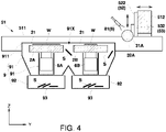
- the two cutting tables 2A and 2B are provided along the Y direction on the horizontal plane. Specifically, the two cutting tables 2A and 2B are arranged such that the substrate placing surfaces 21 (holding surfaces), which are the upper surfaces of the cutting tables, are positioned on the same horizontal plane (positioned at the same height in the Z direction) (see FIG. 4 ), and centers (specifically, rotation centers by the rotation mechanisms 6A and 6B) of the substrate placing surfaces 21 are positioned on the same straight line extending in the Y direction (see FIG. 3 ).
- the two cutting tables 2A and 2B adsorb and hold the molded substrate W, and as illustrated in FIG. 2 , two vacuum pumps 7A and 7B for adsorbing and holding the molded substrate are arranged corresponding to the two cutting tables 2A and 2B.
- Each of the vacuum pumps 7A and 7B is, for example, a liquid-ring vacuum pump, and is provided obliquely below the corresponding cutting tables 2A and 2B along the X direction, and the two vacuum pumps 7A and 7B are provided side by side along the Y direction.
- the two spindles 32A and 32B of the cutting mechanism 3 are provided such that rotation axes thereof are along the X direction, and such that the rotary blades 31A and 31B attached thereto are arranged to be opposed to each other (See FIGS. 3 and 5 ).
- the rotary blade 31A of the spindle 32A and the rotary blade 31B of the spindle 32B rotate on a plane including the Y direction and the Z direction to cut the molded substrate W held by each of the cutting tables 2A and 2B.
- the substrate cutting module B is provided with a liquid supply mechanism 8 having a jet nozzle 81 that jets cutting water (machining liquid) in order to suppress frictional heat generated by the rotary blades 31A and 31B.
- the jet nozzle 81 is supported by, for example, a Z-direction moving unit 53 to be described later.
- the moving mechanism 5 linearly moves each of the two spindles 32A and 32B independently in the X direction, the Y direction, and the Z direction.
- the moving mechanism 5 includes a Y-direction moving unit 51 that linearly moves the spindles 32A and 32B in the Y direction, an X-direction moving unit 52 that linearly moves the spindles 32A and 32B in the X direction, and a Z-direction moving unit 53 that linearly moves the spindles 32A and 32B in the Z direction.
- the Y-direction moving unit 51 is commonly used for the two cutting tables 2A and 2B, and includes a pair of Y-direction guide rails 511 provided along the Y-direction with the two cutting tables 2A and 2B interposed therebetween, and a support 512 that moves along the pair of Y-direction guide rails 511 and supports the spindles 32A and 32B via the X-direction moving unit 52 and the Z-direction moving unit 53.
- the pair of Y-direction guide rails 511 is provided on the sides of the two cutting tables 2A and 2B provided along the Y direction.
- the support 512 is, for example, gate-shaped, and has a shape extending in the X direction.
- the support 512 linearly reciprocates on the pair of Y-direction guide rails 511 by, for example, a ball screw mechanism 513 extending in the Y direction.
- the ball screw mechanism 513 is driven by a drive source (not illustrated) such as a servo motor.
- the support 512 may be configured to reciprocate by other linear motion mechanism such as a linear motor.
- the X-direction moving unit 52 includes an X-direction guide rail 521 provided along the X-direction on the support 512, and an X-direction slider 522 that moves along the X-direction guide rail 521.
- the X-direction slider 522 is driven by, for example, a linear motor (not illustrated), and linearly reciprocates on the X-direction guide rail 521.
- the two X-direction sliders 522 are provided corresponding to the two spindles 32A and 32B. Accordingly, the two spindles 32A and 32B are movable in the X direction independently of each other.
- the X-direction slider 522 may be configured to reciprocate by other linear motion mechanism using a ball screw mechanism.
- the Z-direction moving unit 53 includes a Z-direction guide rail 531 provided along the Z-direction in each X-direction slider 522, and a Z-direction slider 532 that moves along the Z-direction guide rail 531 and supports the spindles 32A and 32B.
- the Z-direction moving unit 53 is provided corresponding to each of the spindles 32A and 32B.
- the Z-direction slider 532 is driven by, for example, an eccentric cam mechanism (not illustrated), and linearly reciprocates on the Z-direction guide rail 531.
- the Z-direction slider 532 may be configured to reciprocate by other linear motion mechanism such as a ball screw mechanism.
- the substrate cutting module B further includes a machining scrap storage unit 9 that stores machining scraps S such as cutting scraps generated by cutting the molded substrate W.
- the machining scrap storage unit 9 is provided below the cutting tables 2A and 2B, and includes a guide part 91 having an upper opening 91X surrounding the cutting tables 2A and 2B in plan view, and a collection container 92 that collects the machining scraps S guided by the guide part 91.
- a collection rate of the machining scraps S can be improved.
- the guide part 91 guides the machining scraps S scattered or dropped from the cutting tables 2A and 2B to the collection container 92.
- the upper opening 91X of the guide part 91 is configured to surround the cutting tables 2A and 2B (see FIG. 3 )
- collection of the machining scraps S is hardly missed, resulting in further improving the collection rate of the machining scraps S.
- the guide part 91 is provided so as to surround the rotation mechanisms 6A and 6B provided under the cutting tables 2A and 2B (see FIG. 4 ), and is configured to protect the rotation mechanisms 6A and 6B from the machining scraps S and the cutting water.
- the machining scrap storage unit 9 is commonly used for the two cutting tables 2A and 2B, it may be provided corresponding to each of the cutting tables 2A and 2B.
- setting a side peripheral wall 911 constituting the upper opening 91X of the guide part 91 at a position (for example, about 5 mm) higher than the substrate placing surface 21 of the cutting table 2A, 2B allows the machining scraps S to easily enter the guide part 91.
- the height position of the side peripheral wall 911 constituting the upper opening 91X of the guide part 91 is set to a height position that does not hinder movement of the cutting mechanism 3 such as the spindles 32A and 32B.
- the collection container 92 collects the machining scraps S that have passed through the guide part 91 by its own weight, and in the present embodiment, is provided corresponding to each of the two cutting tables 2A and 2B as illustrated in FIG. 4 and the like.
- the two collection containers 92 are configured to be independently removable from the cutting apparatus 100. With this configuration, maintainability such as disposal of the machining scraps S can be improved.
- one collection container 92 may be provided under the whole cutting table, or three or more collection containers may be provided.
- the machining scrap storage unit 9 includes a separation part 93 that separates cutting water and machining scraps.
- a separation part 93 for example, a filter such as a porous plate that allows cutting water to pass through can be provided at a bottom surface of the collection container 92.
- the separation part 93 enables collection of the machining scraps S without storing the cutting water in the collection container 92. Further, the cutting water having passed through the filter is returned to the liquid supply mechanism 8 so as to be reused as the cutting water.
- Cutting on the cutting table 2A is performed by moving the two spindles 32A and 32B in the X, Y, and Z directions by the moving mechanism 5 with respect to the cutting table 2A fixed in the X, Y, and Z directions.
- the Y-direction moving unit 51 moves the spindles 32A and 32B in the Y direction, whereby the molded substrate W is cut along the Y direction.
- the cutting table 2A is rotated by, for example, 90 degrees in the ⁇ direction by the rotation mechanism 6A, and then, the spindles 32A and 32B are sequentially moved in the Y direction while being shifted by the predetermined distance in the X direction as described above, whereby the plurality of pieces of the molded substrate W are cut along the Y direction.
- the molded substrate W held on the cutting table 2A is cut into a lattice shape so as to be divided into individual pieces.
- cutting on the cutting table 2B is performed by moving the two spindles 32A and 32B in the X, Y, and Z directions by the moving mechanism 5 with respect to the cutting table 2B fixed in the X, Y, and Z directions.
- the Y-direction moving unit 51 moves the spindles 32A and 32B in the Y direction, whereby the molded substrate W on the cutting table 2B is cut along the Y direction.
- the molded substrate W is cut into a plurality of pieces in the X direction. Then, the cutting table 2B is rotated by, for example, 90 degrees in the ⁇ direction by the rotation mechanism 6B, and then, as described above, the spindles 32A and 32B are sequentially moved in the Y direction while being shifted by the predetermined distance in the X direction, whereby the molded substrate W is cut along the Y direction.
- the molded substrate W held on the cutting table 2B is cut into a lattice shape so as to be divided into individual pieces.
- the cutting processing on the cutting table 2A and the cutting processing on the cutting table 2B are alternately performed separately, the cutting processing on the cutting table 2A and the cutting processing on the cutting table 2B may be simultaneously performed by moving the spindles 32A and 32B across the cutting table 2A and the cutting table 2B by the Y-direction moving unit 51.
- the cutting mechanism 3 (rotary tool 30) moved by the moving mechanism 5 cuts the molded substrate W with respect to the cutting tables 2A and 2B fixed in the X, Y, and Z directions, a moving mechanism that moves the cutting tables 2A and 2B is not required, resulting in eliminating a need for a protective cover such as a bellows cover. As a result, it is possible to suppress a decrease in an operating rate of the cutting apparatus 100 due to a failure of the protective cover, and improve productivity of the cutting apparatus 100.
- the pair of Y-direction guide rails 511 provided in the Y direction is provided so as to sandwich the cutting tables 2A and 2B, a pitch of the pair of Y-direction guide rails 511 can be increased. As a result, influence of a positional deviation in the Z direction between the Y-direction guide rails 511 on machining can be reduced. Specifically, as illustrated in FIG. 6 , since a pitch L' of the pair of guide rails 511 is larger than a pitch L in a conventional configuration, a deviation in an orthogonality ⁇ between the rotary blade and the machining table can be reduced.
- the Y-direction moving unit 51 (specifically, the Y-direction guide rail 511 and the ball screw mechanism 513) located at the lowest in the moving mechanism 5 is located on the side of the cutting tables 2A and 2B, as illustrated in FIG. 7 , the Y-direction moving unit 51 is configured to be separated from the water section, which makes it possible to reduce a risk of a failure caused by water in the Y-direction moving unit 51 and to prolong the apparatus life.
- the present invention is not limited thereto, and a cutting apparatus of a single-cut table system having a single-spindle configuration, a cutting apparatus of the single-cut table system having a twin-spindle configuration, or the like are applicable.
- the two cutting tables of the twin-cut table system are provided along the Y direction
- a plurality of cutting tables may be provided along the X direction.
- the positions of the cutting tables in the Y direction may be the same or may be deviated from each other.
- a conveyance mechanism capable of accessing each cutting table it is possible to transport a substrate yet to be cut to the cutting table or carry out the substrate from the cutting table.
- the machining apparatus of the present invention may perform machining other than cutting, and may perform other machining such as cutting and grinding.
Landscapes
- Engineering & Computer Science (AREA)
- Mechanical Engineering (AREA)
- Life Sciences & Earth Sciences (AREA)
- Forests & Forestry (AREA)
- Manufacturing & Machinery (AREA)
- Microelectronics & Electronic Packaging (AREA)
- Dicing (AREA)
- Machine Tool Units (AREA)
- Nonmetal Cutting Devices (AREA)
- Details Of Cutting Devices (AREA)
- Electrical Discharge Machining, Electrochemical Machining, And Combined Machining (AREA)
- Auxiliary Devices For Machine Tools (AREA)
- Constituent Portions Of Griding Lathes, Driving, Sensing And Control (AREA)
- Confectionery (AREA)
- Disintegrating Or Milling (AREA)
- Polarising Elements (AREA)
- Processing Of Stones Or Stones Resemblance Materials (AREA)
Abstract
Description
- The present invention relates to a machining apparatus.
- Conventionally, a cutting device is used when an electronic component such as a resin-molded substrate is cut into pieces, and for example, a cutting device as shown in
Patent Literature 1 is known. The cutting device includes a chuck table that holds a workpiece, and a moving mechanism such as a ball screw that linearly moves the chuck table. In addition, the cutting device includes a protective plate for protecting the moving mechanism from machining scraps generated by cutting or a machining liquid supplied during cutting. - The protective plate is configured to be extendable along with the chuck table moves. Specifically, the protective plate includes a bellows cover provided so as to surround an upper side and a side of the moving mechanism, and a plurality of plates provided on an upper surface of the bellows cover. The plurality of plates are sequentially overlapped with each other and slide with the movement of the chuck table.
- When a workpiece is cut into pieces by the cutting device, a product portion and cutting scraps such as remnants are generated. The product portion is held by a chuck mechanism provided on the chuck table.
- However, since the cutting scraps are not held by the chuck mechanism, the cutting scraps fall from the chuck table after being cut from the product portion. The dropped cutting scraps accumulate on upper surfaces of the respective plates of the protective plate. When the chuck table moves in this state, the cutting scraps might enter between the plates overlapped with each other while the protective plate contracts with the movement of the chuck table. If the machining scraps enter between the plates, they might not only prevent the expansion and contraction of the protective plate but also contact with the bellows cover and damage the bellows cover. When the bellows cover is damaged, a machining liquid leaks to the moving mechanism to cause rusts to be generated in the moving mechanism, so that malfunction or failure occurs. As a result, it is necessary to frequently perform maintenance work and replacement work for the malfunction or failure, and an operating rate of the cutting device decreases.
- Patent Literature 1:
Japanese Patent No. 6043648 - Therefore, the present invention has been made to solve the above problems, and a main object thereof is to eliminate a need for a moving mechanism that moves a machining table and eliminate a need for a protective cover such as a bellows cover.
- Specifically, a machining apparatus according to the present invention includes: a machining table that holds a workpiece; a machining mechanism that machines the workpiece with a rotary tool while using a machining liquid; and a moving mechanism that linearly moves the machining mechanism at least in each of X and Y directions on a horizontal plane, in which the machining mechanism moved by the moving mechanism machines the workpiece with respect to the machining table fixed at least in the X and Y directions.
- According to thus configured present invention, it is possible to eliminate a need for a moving mechanism that moves a machining table and eliminate a need for a protective cover such as a bellows cover.
-
-
FIG. 1 is a view schematically illustrating a configuration of a cutting apparatus according to an embodiment of the present invention. -
FIG. 2 is a perspective view schematically illustrating a configuration of a substrate cutting module according to the embodiment. -
FIG. 3 is a view (plan view) schematically illustrating the configuration of the substrate cutting module according to the embodiment as viewed from a Z direction. -
FIG. 4 is a view (side view) schematically illustrating the configuration of the substrate cutting module according to the embodiment as viewed from an X direction. -
FIG. 5 is a view (front view) schematically illustrating the configuration of the substrate cutting module according to the embodiment as viewed from a Y direction. -
FIG. 6 is a schematic view illustrating an effect of the present embodiment compared with a conventional configuration. -
FIG. 7 is a schematic view illustrating an effect of the present embodiment compared with the conventional configuration. -
- 100
- cutting apparatus (machining apparatus)
- W
- molded substrate (workpiece)
- 2A, 2B
- cutting table (machining table)
- 3
- cutting mechanism (machining mechanism)
- 30
- rotary tool
- 31A, 31B
- rotary blade
- 32A, 32B
- spindle
- 5
- moving mechanism
- 51
- Y-direction moving unit
- 511
- Y-direction guide rail
- 512
- support
- 52
- X-direction moving unit
- Next, the present invention will be described in more detail with reference to examples. Note that the present invention is not limited by the following description.
- As described above, the machining apparatus of the present invention includes: a machining table that holds a workpiece; a machining mechanism that machines the workpiece with a rotary tool while using a machining liquid; and a moving mechanism that linearly moves the machining mechanism at least in each of X and Y directions on a horizontal plane, in which the machining mechanism moved by the moving mechanism machines the workpiece with respect to the machining table fixed at least in the X and Y directions.
- In this machining apparatus, since the machining mechanism moved by the moving mechanism machines the workpiece with respect to the machining table fixed at least in the X and Y directions, it is possible to eliminate a need for a moving mechanism that moves the machining table in the X direction or the Y direction and a need for a protective cover such as a bellows cover. As a result, it is possible to suppress a decrease in an operating rate of the apparatus due to a damage of a protective cover such as a bellows cover and improve productivity of the apparatus.
- As a specific embodiment of the moving mechanism that moves the machining mechanism at least in the X and Y directions, the moving mechanism may include an X-direction moving unit that linearly moves the machining mechanism in the X direction and a Y-direction moving unit that linearly moves the machining mechanism in the Y direction, and the Y-direction moving unit has a pair of Y-direction guide rails provided along the Y direction with the machining table interposed therebetween, and a support that moves along the pair of Y-direction guide rails and supports the machining mechanism via the X-direction moving unit.
- Since the pair of Y-direction guide rails provided in the Y direction is provided so as to sandwich the machining table, a pitch of the pair of Y-direction guide rails can be increased. As a result, influence of a positional deviation in a Z direction between the Y-direction guide rails on machining can be reduced. Specifically, it is possible to reduce a deviation in orthogonality between a rotary tool (for example, the rotary blade) and the machining table, and to improve machining accuracy. In addition, a Y-direction guide rail having a lower specification than a conventional one can be used.
- In order to increase a workpiece processing capability in one machining apparatus, two or more of the machining tables may be provided.
- In this configuration, the two or more machining tables are desirably provided along the Y direction on the horizontal plane.
- With this configuration, since the two or more machining tables are provided along the Y direction, parallelism in the Y direction of the moving mechanism with respect to the two or more machining tables can be adjusted at once. In addition, when a workpiece is processed on one machining table, another processing such as conveyance can be performed on the other machining table.
- In a case where the machining mechanism is configured to cut the workpiece into pieces with a rotary blade, it is particularly crucial that a cutting direction by the rotary blade and the Y direction of the moving mechanism coincide with each other (i.e., a rotation axis direction of the rotary blade and the Y direction of the moving mechanism are orthogonal to each other.). In the present invention, it is only necessary to position the rotary blade with respect to the support of the Y-direction moving unit, and as compared with a conventional case where a rotation axis direction of a rotary blade is positioned with respect to a machining table that moves independently from the rotary blade, it is easy to position the rotary blade and the machining table.
- As a specific embodiment of the machining apparatus of the present invention, it is desirable that the workpiece is a resin-molded substrate, and the machining mechanism is configured to cut the molded substrate into a plurality of products with the rotary blade.
- In the following, an embodiment of a machining apparatus according to the present invention will be described with reference to the drawings. Note that any of the drawings shown below is schematically illustrated while being omitted or exaggerated as appropriate for easy understanding. The same components are denoted by the same reference numerals, and description thereof will be omitted as appropriate.
- As illustrated in
FIG. 1 , amachining apparatus 100 of the present embodiment is a cutting apparatus that cuts a molded substrate W, which is a workpiece, into a plurality of products P. Thecutting apparatus 100 includes a substrate supply module A, a substrate cutting module B, and an inspection module C as components. Each component (each module A to C) is detachable from and attachable with another component. - The substrate supply module A supplies the molded substrate W to the substrate cutting module B. Specifically, the substrate supply module A has a
substrate supply mechanism 1 for supplying the molded substrate W to the substrate cutting module B. Then, the molded substrate W is carried out from thesubstrate supply mechanism 1 and transferred to the substrate cutting module B by a transfer mechanism (not illustrated). - The substrate cutting module B cuts the molded substrate W using a cutting mechanism (machining mechanism) 3 having a
rotary tool 30 including a rotary blade and a spindle, and has, for example, a twin spindle configuration and a twin cut table configuration. Specifically, the substrate cutting module B includes two cutting tables (machining tables) 2A and 2B and twospindles rotary blades jig 4A is attached to the cutting table 2A, and a cuttingjig 4B is attached to the cutting table 2B. A specific configuration of the substrate cutting module B will be described later. - The inspection module C is provided with an inspection table 10. There is placed on the inspection table 10 an aggregate including a plurality of the products P cut into pieces from the molded substrate W. The plurality of products P are inspected by an inspection camera (not illustrated), and are sorted into a non-defective product and a defective product. The non-defective product is stored in a
tray 11. - In the present embodiment, a control unit CTL is provided in the substrate supply module A, the control unit performing all operations and controls such as operation of the
cutting apparatus 100, conveyance of the molded substrate W, cutting of the molded substrate W, and inspection of the product P. The present invention is not limited thereto, and the control unit CTL may be provided in other module. - Next, a specific configuration of the substrate cutting module B in the
cutting apparatus 100 of the present embodiment will be described below. For convenience, directions orthogonal to each other on a plane (horizontal plane) along the substrate placing surface 21 (holding surface) which is an upper surface of the cutting table 2A, 2B are defined as an X direction and a Y direction, respectively, and a vertical direction orthogonal to the X direction and the Y direction is defined as a Z direction. Specifically, a right-left direction inFIG. 3 is defined as the X direction, and an up-down direction is defined as the Y direction. InFIG. 2 , a part of a Y-direction guide rail 511 on the front side is omitted. - As illustrated in
FIGS. 2 to 5 , the substrate cutting module B includes two cutting tables 2A and 2B that hold the molded substrate W, thecutting mechanism 3 having the tworotary tools 30 including therotary blades spindles mechanism 5 that linearly moves the twospindles cutting mechanism 3 in each of the X, Y, and Z directions. - The two cutting tables 2A and 2B are fixed in the X direction, the Y direction, and the Z direction. The cutting table 2A is rotatable in a θ direction by a
rotation mechanism 6A provided below the cutting table 2A. Further, the cutting table 2B is rotatable in the θ direction by arotation mechanism 6B provided under the cutting table 2B. - The two cutting tables 2A and 2B are provided along the Y direction on the horizontal plane. Specifically, the two cutting tables 2A and 2B are arranged such that the substrate placing surfaces 21 (holding surfaces), which are the upper surfaces of the cutting tables, are positioned on the same horizontal plane (positioned at the same height in the Z direction) (see
FIG. 4 ), and centers (specifically, rotation centers by therotation mechanisms FIG. 3 ). - In addition, the two cutting tables 2A and 2B adsorb and hold the molded substrate W, and as illustrated in
FIG. 2 , twovacuum pumps 7A and 7B for adsorbing and holding the molded substrate are arranged corresponding to the two cutting tables 2A and 2B. Each of thevacuum pumps 7A and 7B is, for example, a liquid-ring vacuum pump, and is provided obliquely below the corresponding cutting tables 2A and 2B along the X direction, and the twovacuum pumps 7A and 7B are provided side by side along the Y direction. - Here, since the cutting tables 2A and 2B are fixed in the X, Y, and Z directions,
pipes vacuum pumps 7A and 7B can be shortened, so that pressure losses of thepipes pipes vacuum pumps 7A and 7B can be reduced, leading to cost reduction. - The two
spindles cutting mechanism 3 are provided such that rotation axes thereof are along the X direction, and such that therotary blades FIGS. 3 and5 ). Therotary blade 31A of thespindle 32A and therotary blade 31B of thespindle 32B rotate on a plane including the Y direction and the Z direction to cut the molded substrate W held by each of the cutting tables 2A and 2B. As illustrated inFIG. 4 , the substrate cutting module B is provided with aliquid supply mechanism 8 having ajet nozzle 81 that jets cutting water (machining liquid) in order to suppress frictional heat generated by therotary blades jet nozzle 81 is supported by, for example, a Z-direction moving unit 53 to be described later. - As illustrated in
FIGS. 2 to 5 , the movingmechanism 5 linearly moves each of the twospindles - Specifically, the moving
mechanism 5 includes a Y-direction moving unit 51 that linearly moves thespindles unit 52 that linearly moves thespindles direction moving unit 53 that linearly moves thespindles - The Y-
direction moving unit 51 is commonly used for the two cutting tables 2A and 2B, and includes a pair of Y-direction guide rails 511 provided along the Y-direction with the two cutting tables 2A and 2B interposed therebetween, and asupport 512 that moves along the pair of Y-direction guide rails 511 and supports thespindles X-direction moving unit 52 and the Z-direction moving unit 53. The pair of Y-direction guide rails 511 is provided on the sides of the two cutting tables 2A and 2B provided along the Y direction. Further, thesupport 512 is, for example, gate-shaped, and has a shape extending in the X direction. - Then, the
support 512 linearly reciprocates on the pair of Y-direction guide rails 511 by, for example, aball screw mechanism 513 extending in the Y direction. Theball screw mechanism 513 is driven by a drive source (not illustrated) such as a servo motor. In addition, thesupport 512 may be configured to reciprocate by other linear motion mechanism such as a linear motor. - The
X-direction moving unit 52 includes anX-direction guide rail 521 provided along the X-direction on thesupport 512, and anX-direction slider 522 that moves along theX-direction guide rail 521. TheX-direction slider 522 is driven by, for example, a linear motor (not illustrated), and linearly reciprocates on theX-direction guide rail 521. In the present embodiment, the twoX-direction sliders 522 are provided corresponding to the twospindles spindles X-direction slider 522 may be configured to reciprocate by other linear motion mechanism using a ball screw mechanism. - The Z-
direction moving unit 53 includes a Z-direction guide rail 531 provided along the Z-direction in eachX-direction slider 522, and a Z-direction slider 532 that moves along the Z-direction guide rail 531 and supports thespindles direction moving unit 53 is provided corresponding to each of thespindles direction slider 532 is driven by, for example, an eccentric cam mechanism (not illustrated), and linearly reciprocates on the Z-direction guide rail 531. In addition, the Z-direction slider 532 may be configured to reciprocate by other linear motion mechanism such as a ball screw mechanism. - Then, as illustrated in
FIGS. 2 to 5 , the substrate cutting module B according to the present embodiment further includes a machiningscrap storage unit 9 that stores machining scraps S such as cutting scraps generated by cutting the molded substrate W. - The machining
scrap storage unit 9 is provided below the cutting tables 2A and 2B, and includes aguide part 91 having anupper opening 91X surrounding the cutting tables 2A and 2B in plan view, and acollection container 92 that collects the machining scraps S guided by theguide part 91. By providing the machiningscrap storage unit 9 below the cutting tables 2A and 2B, a collection rate of the machining scraps S can be improved. - The
guide part 91 guides the machining scraps S scattered or dropped from the cutting tables 2A and 2B to thecollection container 92. In the present embodiment, since theupper opening 91X of theguide part 91 is configured to surround the cutting tables 2A and 2B (seeFIG. 3 ), collection of the machining scraps S is hardly missed, resulting in further improving the collection rate of the machining scraps S. Theguide part 91 is provided so as to surround therotation mechanisms FIG. 4 ), and is configured to protect therotation mechanisms - Although in the present embodiment, the machining
scrap storage unit 9 is commonly used for the two cutting tables 2A and 2B, it may be provided corresponding to each of the cutting tables 2A and 2B. In addition, as illustrated inFIGS. 4 and5 , setting a sideperipheral wall 911 constituting theupper opening 91X of theguide part 91 at a position (for example, about 5 mm) higher than thesubstrate placing surface 21 of the cutting table 2A, 2B allows the machining scraps S to easily enter theguide part 91. The height position of the sideperipheral wall 911 constituting theupper opening 91X of theguide part 91 is set to a height position that does not hinder movement of thecutting mechanism 3 such as thespindles - The
collection container 92 collects the machining scraps S that have passed through theguide part 91 by its own weight, and in the present embodiment, is provided corresponding to each of the two cutting tables 2A and 2B as illustrated inFIG. 4 and the like. The twocollection containers 92 are configured to be independently removable from thecutting apparatus 100. With this configuration, maintainability such as disposal of the machining scraps S can be improved. In consideration of a size of the molded substrate W, a size and an amount of the machining scraps S, workability, and the like, onecollection container 92 may be provided under the whole cutting table, or three or more collection containers may be provided. - As illustrated in
FIG. 4 and the like, the machiningscrap storage unit 9 includes aseparation part 93 that separates cutting water and machining scraps. As a configuration of theseparation part 93, for example, a filter such as a porous plate that allows cutting water to pass through can be provided at a bottom surface of thecollection container 92. Theseparation part 93 enables collection of the machining scraps S without storing the cutting water in thecollection container 92. Further, the cutting water having passed through the filter is returned to theliquid supply mechanism 8 so as to be reused as the cutting water. - Next, an example of operation of the substrate cutting module B will be described.
- Cutting on the cutting table 2A is performed by moving the two
spindles mechanism 5 with respect to the cutting table 2A fixed in the X, Y, and Z directions. For example, after theX-direction moving unit 52 and the Z-direction moving unit 53 fix thespindle 32A at desired positions in the X direction and the Z direction, the Y-direction moving unit 51 moves thespindles rotation mechanism 6A, and then, thespindles - Similarly to the cutting on the cutting table 2A, cutting on the cutting table 2B is performed by moving the two
spindles mechanism 5 with respect to the cutting table 2B fixed in the X, Y, and Z directions. For example, after theX-direction moving unit 52 and the Z-direction moving unit 53 fix thespindles direction moving unit 51 moves thespindles rotation mechanism 6B, and then, as described above, thespindles - Although in the above operation, the cutting processing on the cutting table 2A and the cutting processing on the cutting table 2B are alternately performed separately, the cutting processing on the cutting table 2A and the cutting processing on the cutting table 2B may be simultaneously performed by moving the
spindles direction moving unit 51. - According to the
cutting apparatus 100 of the present embodiment, since the cutting mechanism 3 (rotary tool 30) moved by the movingmechanism 5 cuts the molded substrate W with respect to the cutting tables 2A and 2B fixed in the X, Y, and Z directions, a moving mechanism that moves the cutting tables 2A and 2B is not required, resulting in eliminating a need for a protective cover such as a bellows cover. As a result, it is possible to suppress a decrease in an operating rate of thecutting apparatus 100 due to a failure of the protective cover, and improve productivity of thecutting apparatus 100. - Since in the present embodiment, the pair of Y-
direction guide rails 511 provided in the Y direction is provided so as to sandwich the cutting tables 2A and 2B, a pitch of the pair of Y-direction guide rails 511 can be increased. As a result, influence of a positional deviation in the Z direction between the Y-direction guide rails 511 on machining can be reduced. Specifically, as illustrated inFIG. 6 , since a pitch L' of the pair ofguide rails 511 is larger than a pitch L in a conventional configuration, a deviation in an orthogonality θ between the rotary blade and the machining table can be reduced. Furthermore, since the pitch between the pair ofguide rails 511 is increased, straightness of the Y-direction moving unit 51 is improved, and as a result, cutting edges of therotary blades direction guide rail 511 having a specification lower than a conventional one can be used. - Since in the present embodiment, the Y-direction moving unit 51 (specifically, the Y-
direction guide rail 511 and the ball screw mechanism 513) located at the lowest in the movingmechanism 5 is located on the side of the cutting tables 2A and 2B, as illustrated inFIG. 7 , the Y-direction moving unit 51 is configured to be separated from the water section, which makes it possible to reduce a risk of a failure caused by water in the Y-direction moving unit 51 and to prolong the apparatus life. - In the present embodiment, since two or more of the cutting tables 2A and 2B do not move in the Y direction at the time of cutting, parallelism of the moving mechanism 5 (Y-direction moving unit 51) in the Y direction with respect to the two or more cutting tables 2A and 2B can be adjusted at once. Specifically, in a case where two cutting tables are provided in a conventional apparatus in which the cutting tables move at the time of cutting, it is necessary to adjust parallelism of the two cutting tables in the Y direction and further adjust the adjusted parallelism in the Y direction and parallelism of the rotary blade in the Y direction (specifically, two adjustments are required). In the present embodiment, however, since the two cutting tables 2A and 2B do not move in the Y direction at the time of cutting, it is only necessary to adjust parallelism of the
rotary blades - In addition, because of the configuration in which the two or more cutting tables 2A and 2B are provided along the Y direction and the
support 512 supporting thespindles - Note that the present invention is not limited to the above embodiment.
- For example, although in the above embodiment, the description has been made of the cutting apparatus of the twin-cut table system having the twin-spindle configuration, the present invention is not limited thereto, and a cutting apparatus of a single-cut table system having a single-spindle configuration, a cutting apparatus of the single-cut table system having a twin-spindle configuration, or the like are applicable.
- Although in the above embodiment, the two cutting tables of the twin-cut table system are provided along the Y direction, a plurality of cutting tables may be provided along the X direction. In this case, the positions of the cutting tables in the Y direction may be the same or may be deviated from each other. In a case where a plurality of cutting tables are provided so as to have positions deviated in the Y direction, by providing a conveyance mechanism capable of accessing each cutting table, it is possible to transport a substrate yet to be cut to the cutting table or carry out the substrate from the cutting table.
- In addition, the machining apparatus of the present invention may perform machining other than cutting, and may perform other machining such as cutting and grinding.
- In addition, the present invention is not limited to the above embodiment, and it goes without saying that various modifications can be made without departing from the gist of the present invention.
- According to the present invention, it is possible to eliminate a need for a moving mechanism that moves a machining table and eliminate a need for a protective cover such as a bellows cover.
Claims (6)
- A machining apparatus comprising:a machining table that holds a workpiece;a machining mechanism that machines the workpiece with a rotary tool while using a machining liquid; anda moving mechanism that linearly moves the machining mechanism at least in each of X and Y directions on a horizontal plane, whereinthe machining mechanism moved by the moving mechanism machines the workpiece with respect to the machining table fixed at least in the X and Y directions.
- The machining apparatus according to claim 1, whereinthe moving mechanism includes an X-direction moving unit that linearly moves the machining mechanism in the X direction and a Y-direction moving unit that linearly moves the machining mechanism in the Y direction, andthe Y-direction moving unit has a pair of Y-direction guide rails provided along the Y direction with the machining table interposed therebetween, and a support that moves along the pair of Y-direction guide rails and supports the machining mechanism via the X-direction moving unit.
- The machining apparatus according to claim 1 or 2, comprising two or more of the machining tables.
- The machining apparatus according to claim 3 referring to claim 2, wherein the two or more machining tables are provided along the Y direction on the horizontal plane.
- The machining apparatus according to any one of claims 1 to 4, wherein the machining mechanism is configured to cut the workpiece into pieces with a rotary blade.
- The machining apparatus according to any one of claims 1 to 5, whereinthe workpiece is a resin-molded substrate, andthe machining mechanism is configured to cut the molded substrate into a plurality of products with the rotary blade.
Applications Claiming Priority (2)
| Application Number | Priority Date | Filing Date | Title |
|---|---|---|---|
| JP2020020562A JP7222941B2 (en) | 2020-02-10 | 2020-02-10 | processing equipment |
| PCT/JP2021/001754 WO2021161744A1 (en) | 2020-02-10 | 2021-01-20 | Machining apparatus |
Publications (2)
| Publication Number | Publication Date |
|---|---|
| EP4104988A1 true EP4104988A1 (en) | 2022-12-21 |
| EP4104988A4 EP4104988A4 (en) | 2023-08-02 |
Family
ID=77293140
Family Applications (1)
| Application Number | Title | Priority Date | Filing Date |
|---|---|---|---|
| EP21753070.8A Pending EP4104988A4 (en) | 2020-02-10 | 2021-01-20 | MACHINING DEVICE |
Country Status (8)
| Country | Link |
|---|---|
| US (1) | US20230074984A1 (en) |
| EP (1) | EP4104988A4 (en) |
| JP (1) | JP7222941B2 (en) |
| KR (1) | KR102755703B1 (en) |
| CN (1) | CN115052710B (en) |
| MX (1) | MX2022009812A (en) |
| TW (1) | TWI788767B (en) |
| WO (1) | WO2021161744A1 (en) |
Families Citing this family (1)
| Publication number | Priority date | Publication date | Assignee | Title |
|---|---|---|---|---|
| CN115284457A (en) * | 2022-08-02 | 2022-11-04 | 北京半导体专用设备研究所(中国电子科技集团公司第四十五研究所) | Edge cutting device of laminating machine |
Family Cites Families (44)
| Publication number | Priority date | Publication date | Assignee | Title |
|---|---|---|---|---|
| US3424357A (en) * | 1966-07-28 | 1969-01-28 | Ppg Industries Inc | Automatically sizing and severing glass sheets |
| DE1602798A1 (en) * | 1967-03-30 | 1971-11-18 | Mueller Karl Gmbh | Drilling and milling machine |
| JPS6043648U (en) | 1983-08-30 | 1985-03-27 | 松下電送株式会社 | automatic paper feeder |
| JPH0811390B2 (en) * | 1989-04-14 | 1996-02-07 | 株式会社川上製作所 | Laminating sheet cutting device |
| DE9422019U1 (en) * | 1994-11-19 | 1997-08-14 | Maschinenfabrik Berthold Hermle AG, 78559 Gosheim | Machine tool, in particular drilling and milling machine |
| FR2743015B1 (en) * | 1995-12-29 | 1998-03-27 | Helis Sa | MOBILE GANTRY MACHINE WITH MOVABLE UPRIGHTS IN RELATION TO EACH OTHER |
| US6006739A (en) * | 1996-11-12 | 1999-12-28 | Micron Technology, Inc. | Method for sawing wafers employing multiple indexing techniques for multiple die dimensions |
| IT1295183B1 (en) * | 1997-09-17 | 1999-05-04 | Biesse Spa | OPERATING MACHINE, AND RELATED PROCEDURE, FOR THE PROCESSING OF FLAT BODIES. |
| US6193048B1 (en) * | 1998-11-24 | 2001-02-27 | Midaco Corporation | Pallet changer |
| DE10026069C2 (en) * | 2000-05-25 | 2003-01-09 | Homag Maschinenbau Ag | CNC machining center and woodworking processes |
| JP2002237472A (en) * | 2001-02-07 | 2002-08-23 | Disco Abrasive Syst Ltd | Workpiece cutting method |
| US7267037B2 (en) * | 2001-05-05 | 2007-09-11 | David Walter Smith | Bidirectional singulation saw and method |
| JP4532895B2 (en) * | 2003-12-18 | 2010-08-25 | 株式会社ディスコ | Plate cutting machine |
| JP4676288B2 (en) * | 2005-09-14 | 2011-04-27 | 株式会社ディスコ | Cutting equipment |
| US8365385B2 (en) * | 2005-12-06 | 2013-02-05 | Musashi Engineering, Inc. | Processing apparatus and method |
| JP4869698B2 (en) * | 2005-12-12 | 2012-02-08 | コマツNtc株式会社 | Machining center |
| JP3945716B2 (en) * | 2005-12-14 | 2007-07-18 | インターナショナル・ビジネス・マシーンズ・コーポレーション | End mill and manufacturing method thereof |
| DE102006013109B4 (en) * | 2006-03-22 | 2010-01-28 | Bernd Butzer | machine tool |
| JP4911761B2 (en) * | 2006-08-31 | 2012-04-04 | 武蔵エンジニアリング株式会社 | Deformable gantry working device |
| JP2008080409A (en) * | 2006-09-25 | 2008-04-10 | Nippei Toyama Corp | Machine tool processing line |
| JP2009090402A (en) * | 2007-10-05 | 2009-04-30 | Disco Abrasive Syst Ltd | Cutting equipment |
| JP2009200089A (en) * | 2008-02-19 | 2009-09-03 | Towa Corp | Cutting method and device for substrate |
| JP5174545B2 (en) | 2008-06-16 | 2013-04-03 | Towa株式会社 | Substrate cutting device |
| US8800124B1 (en) * | 2009-11-23 | 2014-08-12 | The Boeing Company | Adjustable fixture for a multi-spindle machine |
| JP5232215B2 (en) * | 2010-12-17 | 2013-07-10 | 平田機工株式会社 | Cutting device |
| JP2012171057A (en) * | 2011-02-22 | 2012-09-10 | Hirata Corp | Cutting apparatus |
| WO2013136952A1 (en) * | 2012-03-14 | 2013-09-19 | アイセル株式会社 | Cutting machine |
| KR101526251B1 (en) * | 2012-10-16 | 2015-06-09 | 호코스 가부시키가이샤 | Machine tool |
| CN103878590A (en) * | 2012-12-19 | 2014-06-25 | 鸿准精密模具(昆山)有限公司 | Machine tool |
| JP6043648B2 (en) | 2013-02-20 | 2016-12-14 | 株式会社ディスコ | Cutting equipment |
| CN103358186B (en) * | 2013-07-12 | 2016-04-13 | 沈阳机床股份有限公司 | Horizontal Machining centers complete machine structure and manufacture method |
| US9508570B2 (en) * | 2013-10-21 | 2016-11-29 | Asm Technology Singapore Pte Ltd | Singulation apparatus and method |
| US9263352B2 (en) * | 2014-01-03 | 2016-02-16 | Asm Technology Singapore Pte Ltd | Singulation apparatus comprising an imaging device |
| JP2016124037A (en) * | 2014-12-26 | 2016-07-11 | 株式会社ジェイテクト | Machine tool |
| JP6465722B2 (en) * | 2015-04-06 | 2019-02-06 | 株式会社ディスコ | Processing equipment |
| JP6552924B2 (en) | 2015-09-02 | 2019-07-31 | 株式会社ディスコ | Processing device |
| EP3311950A1 (en) * | 2016-10-19 | 2018-04-25 | Bystronic Laser AG | Transport device, method and computer program product for loading and unloading at least one material machining machine |
| JP6791581B2 (en) | 2016-11-11 | 2020-11-25 | 株式会社ディスコ | Jig table for cutting package substrate |
| JP6955918B2 (en) * | 2017-07-03 | 2021-10-27 | 株式会社ディスコ | Substrate processing method |
| JP6227184B1 (en) | 2017-07-04 | 2017-11-08 | 明 杉山 | Flexible multiple table device |
| JP6876586B2 (en) * | 2017-09-27 | 2021-05-26 | Towa株式会社 | Processing equipment |
| JP7028607B2 (en) * | 2017-11-06 | 2022-03-02 | 株式会社ディスコ | Cutting equipment |
| JP7102157B2 (en) * | 2018-02-08 | 2022-07-19 | Towa株式会社 | Cutting device and manufacturing method of cut products |
| JP2019136856A (en) | 2018-02-15 | 2019-08-22 | 株式会社ナガセインテグレックス | Machine tool |
-
2020
- 2020-02-10 JP JP2020020562A patent/JP7222941B2/en active Active
-
2021
- 2021-01-20 EP EP21753070.8A patent/EP4104988A4/en active Pending
- 2021-01-20 MX MX2022009812A patent/MX2022009812A/en unknown
- 2021-01-20 CN CN202180013121.8A patent/CN115052710B/en active Active
- 2021-01-20 WO PCT/JP2021/001754 patent/WO2021161744A1/en not_active Ceased
- 2021-01-20 KR KR1020227029770A patent/KR102755703B1/en active Active
- 2021-01-20 US US17/798,434 patent/US20230074984A1/en not_active Abandoned
- 2021-01-25 TW TW110102730A patent/TWI788767B/en active
Also Published As
| Publication number | Publication date |
|---|---|
| WO2021161744A1 (en) | 2021-08-19 |
| KR20220127936A (en) | 2022-09-20 |
| JP7222941B2 (en) | 2023-02-15 |
| US20230074984A1 (en) | 2023-03-09 |
| MX2022009812A (en) | 2022-11-09 |
| EP4104988A4 (en) | 2023-08-02 |
| CN115052710A (en) | 2022-09-13 |
| TWI788767B (en) | 2023-01-01 |
| CN115052710B (en) | 2024-10-29 |
| JP2021122931A (en) | 2021-08-30 |
| TW202130455A (en) | 2021-08-16 |
| KR102755703B1 (en) | 2025-01-21 |
Similar Documents
| Publication | Publication Date | Title |
|---|---|---|
| EP4104971A1 (en) | Machining apparatus | |
| CN219094012U (en) | Automatic stealthy cutting equipment of wafer | |
| CN107030902A (en) | Topping machanism | |
| JP7084519B1 (en) | Processing equipment | |
| US20230074984A1 (en) | Machining apparatus | |
| JP7645142B2 (en) | Processing device and manufacturing method of processed products | |
| KR20170072136A (en) | Machining apparatus | |
| CN115139131A (en) | Full-automatic multi-channel machining machine tool for feeding and discharging | |
| JP7799398B2 (en) | Processing device and manufacturing method of processed product | |
| JP7548853B2 (en) | Processing device and manufacturing method of processed products | |
| JP7496328B2 (en) | Processing device and manufacturing method of processed products | |
| JP7430154B2 (en) | Processing equipment and method for manufacturing processed products | |
| KR102865073B1 (en) | Processing device and method for manufacturing processed products | |
| JP2007081101A (en) | Cutting equipment |
Legal Events
| Date | Code | Title | Description |
|---|---|---|---|
| STAA | Information on the status of an ep patent application or granted ep patent |
Free format text: STATUS: THE INTERNATIONAL PUBLICATION HAS BEEN MADE |
|
| PUAI | Public reference made under article 153(3) epc to a published international application that has entered the european phase |
Free format text: ORIGINAL CODE: 0009012 |
|
| STAA | Information on the status of an ep patent application or granted ep patent |
Free format text: STATUS: REQUEST FOR EXAMINATION WAS MADE |
|
| 17P | Request for examination filed |
Effective date: 20220822 |
|
| AK | Designated contracting states |
Kind code of ref document: A1 Designated state(s): AL AT BE BG CH CY CZ DE DK EE ES FI FR GB GR HR HU IE IS IT LI LT LU LV MC MK MT NL NO PL PT RO RS SE SI SK SM TR |
|
| RIN1 | Information on inventor provided before grant (corrected) |
Inventor name: AZUMA, HIDEKAZU Inventor name: SHIRAI, KATSUMASA Inventor name: HORI, SATOKO Inventor name: FUKAI, MOTOKI |
|
| DAV | Request for validation of the european patent (deleted) | ||
| DAX | Request for extension of the european patent (deleted) | ||
| A4 | Supplementary search report drawn up and despatched |
Effective date: 20230704 |
|
| RIC1 | Information provided on ipc code assigned before grant |
Ipc: B23Q 39/02 20060101ALI20230628BHEP Ipc: H05K 3/00 20060101ALI20230628BHEP Ipc: H01L 21/301 20060101ALI20230628BHEP Ipc: B23Q 1/62 20060101ALI20230628BHEP Ipc: B23Q 1/01 20060101ALI20230628BHEP Ipc: B26D 7/02 20060101ALI20230628BHEP Ipc: B26D 1/18 20060101AFI20230628BHEP |