EP4101372B1 - Flexible hochdichte mappingkatheterspitzen und flexible ablationskatheterspitzen mit integrierten hochdichten mappingelektroden - Google Patents
Flexible hochdichte mappingkatheterspitzen und flexible ablationskatheterspitzen mit integrierten hochdichten mappingelektroden Download PDFInfo
- Publication number
- EP4101372B1 EP4101372B1 EP22188371.3A EP22188371A EP4101372B1 EP 4101372 B1 EP4101372 B1 EP 4101372B1 EP 22188371 A EP22188371 A EP 22188371A EP 4101372 B1 EP4101372 B1 EP 4101372B1
- Authority
- EP
- European Patent Office
- Prior art keywords
- microelectrodes
- catheter
- density mapping
- flexible
- arm
- Prior art date
- Legal status (The legal status is an assumption and is not a legal conclusion. Google has not performed a legal analysis and makes no representation as to the accuracy of the status listed.)
- Active
Links
Images


Classifications
-
- A—HUMAN NECESSITIES
- A61—MEDICAL OR VETERINARY SCIENCE; HYGIENE
- A61N—ELECTROTHERAPY; MAGNETOTHERAPY; RADIATION THERAPY; ULTRASOUND THERAPY
- A61N1/00—Electrotherapy; Circuits therefor
- A61N1/02—Details
- A61N1/04—Electrodes
- A61N1/05—Electrodes for implantation or insertion into the body, e.g. heart electrode
- A61N1/0551—Spinal or peripheral nerve electrodes
- A61N1/0553—Paddle shaped electrodes, e.g. for laminotomy
-
- A—HUMAN NECESSITIES
- A61—MEDICAL OR VETERINARY SCIENCE; HYGIENE
- A61B—DIAGNOSIS; SURGERY; IDENTIFICATION
- A61B18/00—Surgical instruments, devices or methods for transferring non-mechanical forms of energy to or from the body
- A61B18/04—Surgical instruments, devices or methods for transferring non-mechanical forms of energy to or from the body by heating
- A61B18/12—Surgical instruments, devices or methods for transferring non-mechanical forms of energy to or from the body by heating by passing a current through the tissue to be heated, e.g. high-frequency current
- A61B18/14—Probes or electrodes therefor
- A61B18/1492—Probes or electrodes therefor having a flexible, catheter-like structure, e.g. for heart ablation
-
- A—HUMAN NECESSITIES
- A61—MEDICAL OR VETERINARY SCIENCE; HYGIENE
- A61B—DIAGNOSIS; SURGERY; IDENTIFICATION
- A61B5/00—Measuring for diagnostic purposes; Identification of persons
- A61B5/24—Detecting, measuring or recording bioelectric or biomagnetic signals of the body or parts thereof
- A61B5/25—Bioelectric electrodes therefor
- A61B5/271—Arrangements of electrodes with cords, cables or leads, e.g. single leads or patient cord assemblies
- A61B5/273—Connection of cords, cables or leads to electrodes
-
- A—HUMAN NECESSITIES
- A61—MEDICAL OR VETERINARY SCIENCE; HYGIENE
- A61B—DIAGNOSIS; SURGERY; IDENTIFICATION
- A61B5/00—Measuring for diagnostic purposes; Identification of persons
- A61B5/24—Detecting, measuring or recording bioelectric or biomagnetic signals of the body or parts thereof
- A61B5/25—Bioelectric electrodes therefor
- A61B5/279—Bioelectric electrodes therefor specially adapted for particular uses
- A61B5/28—Bioelectric electrodes therefor specially adapted for particular uses for electrocardiography [ECG]
- A61B5/283—Invasive
- A61B5/287—Holders for multiple electrodes, e.g. electrode catheters for electrophysiological study [EPS]
-
- A—HUMAN NECESSITIES
- A61—MEDICAL OR VETERINARY SCIENCE; HYGIENE
- A61B—DIAGNOSIS; SURGERY; IDENTIFICATION
- A61B5/00—Measuring for diagnostic purposes; Identification of persons
- A61B5/68—Arrangements of detecting, measuring or recording means, e.g. sensors, in relation to patient
- A61B5/6846—Arrangements of detecting, measuring or recording means, e.g. sensors, in relation to patient specially adapted to be brought in contact with an internal body part, i.e. invasive
- A61B5/6847—Arrangements of detecting, measuring or recording means, e.g. sensors, in relation to patient specially adapted to be brought in contact with an internal body part, i.e. invasive mounted on an invasive device
- A61B5/6852—Catheters
- A61B5/6858—Catheters with a distal basket, e.g. expandable basket
-
- A—HUMAN NECESSITIES
- A61—MEDICAL OR VETERINARY SCIENCE; HYGIENE
- A61B—DIAGNOSIS; SURGERY; IDENTIFICATION
- A61B5/00—Measuring for diagnostic purposes; Identification of persons
- A61B5/68—Arrangements of detecting, measuring or recording means, e.g. sensors, in relation to patient
- A61B5/6846—Arrangements of detecting, measuring or recording means, e.g. sensors, in relation to patient specially adapted to be brought in contact with an internal body part, i.e. invasive
- A61B5/6847—Arrangements of detecting, measuring or recording means, e.g. sensors, in relation to patient specially adapted to be brought in contact with an internal body part, i.e. invasive mounted on an invasive device
- A61B5/6852—Catheters
- A61B5/6859—Catheters with multiple distal splines
-
- A—HUMAN NECESSITIES
- A61—MEDICAL OR VETERINARY SCIENCE; HYGIENE
- A61B—DIAGNOSIS; SURGERY; IDENTIFICATION
- A61B5/00—Measuring for diagnostic purposes; Identification of persons
- A61B5/68—Arrangements of detecting, measuring or recording means, e.g. sensors, in relation to patient
- A61B5/6846—Arrangements of detecting, measuring or recording means, e.g. sensors, in relation to patient specially adapted to be brought in contact with an internal body part, i.e. invasive
- A61B5/6867—Arrangements of detecting, measuring or recording means, e.g. sensors, in relation to patient specially adapted to be brought in contact with an internal body part, i.e. invasive specially adapted to be attached or implanted in a specific body part
- A61B5/6869—Heart
-
- A—HUMAN NECESSITIES
- A61—MEDICAL OR VETERINARY SCIENCE; HYGIENE
- A61N—ELECTROTHERAPY; MAGNETOTHERAPY; RADIATION THERAPY; ULTRASOUND THERAPY
- A61N1/00—Electrotherapy; Circuits therefor
- A61N1/02—Details
- A61N1/04—Electrodes
- A61N1/0404—Electrodes for external use
- A61N1/0472—Structure-related aspects
- A61N1/0476—Array electrodes (including any electrode arrangement with more than one electrode for at least one of the polarities)
-
- A—HUMAN NECESSITIES
- A61—MEDICAL OR VETERINARY SCIENCE; HYGIENE
- A61N—ELECTROTHERAPY; MAGNETOTHERAPY; RADIATION THERAPY; ULTRASOUND THERAPY
- A61N1/00—Electrotherapy; Circuits therefor
- A61N1/02—Details
- A61N1/04—Electrodes
- A61N1/05—Electrodes for implantation or insertion into the body, e.g. heart electrode
- A61N1/0551—Spinal or peripheral nerve electrodes
-
- A—HUMAN NECESSITIES
- A61—MEDICAL OR VETERINARY SCIENCE; HYGIENE
- A61N—ELECTROTHERAPY; MAGNETOTHERAPY; RADIATION THERAPY; ULTRASOUND THERAPY
- A61N1/00—Electrotherapy; Circuits therefor
- A61N1/18—Applying electric currents by contact electrodes
- A61N1/32—Applying electric currents by contact electrodes alternating or intermittent currents
- A61N1/36—Applying electric currents by contact electrodes alternating or intermittent currents for stimulation
- A61N1/3605—Implantable neurostimulators for stimulating central or peripheral nerve system
- A61N1/3606—Implantable neurostimulators for stimulating central or peripheral nerve system adapted for a particular treatment
- A61N1/36071—Pain
-
- A—HUMAN NECESSITIES
- A61—MEDICAL OR VETERINARY SCIENCE; HYGIENE
- A61B—DIAGNOSIS; SURGERY; IDENTIFICATION
- A61B18/00—Surgical instruments, devices or methods for transferring non-mechanical forms of energy to or from the body
- A61B2018/00053—Mechanical features of the instrument of device
- A61B2018/0016—Energy applicators arranged in a two- or three dimensional array
-
- A—HUMAN NECESSITIES
- A61—MEDICAL OR VETERINARY SCIENCE; HYGIENE
- A61B—DIAGNOSIS; SURGERY; IDENTIFICATION
- A61B18/00—Surgical instruments, devices or methods for transferring non-mechanical forms of energy to or from the body
- A61B2018/00053—Mechanical features of the instrument of device
- A61B2018/00214—Expandable means emitting energy, e.g. by elements carried thereon
-
- A—HUMAN NECESSITIES
- A61—MEDICAL OR VETERINARY SCIENCE; HYGIENE
- A61B—DIAGNOSIS; SURGERY; IDENTIFICATION
- A61B18/00—Surgical instruments, devices or methods for transferring non-mechanical forms of energy to or from the body
- A61B2018/00315—Surgical instruments, devices or methods for transferring non-mechanical forms of energy to or from the body for treatment of particular body parts
- A61B2018/00345—Vascular system
- A61B2018/00351—Heart
- A61B2018/00357—Endocardium
-
- A—HUMAN NECESSITIES
- A61—MEDICAL OR VETERINARY SCIENCE; HYGIENE
- A61B—DIAGNOSIS; SURGERY; IDENTIFICATION
- A61B18/00—Surgical instruments, devices or methods for transferring non-mechanical forms of energy to or from the body
- A61B2018/00571—Surgical instruments, devices or methods for transferring non-mechanical forms of energy to or from the body for achieving a particular surgical effect
- A61B2018/00577—Ablation
-
- A—HUMAN NECESSITIES
- A61—MEDICAL OR VETERINARY SCIENCE; HYGIENE
- A61B—DIAGNOSIS; SURGERY; IDENTIFICATION
- A61B18/00—Surgical instruments, devices or methods for transferring non-mechanical forms of energy to or from the body
- A61B2018/00636—Sensing and controlling the application of energy
- A61B2018/00773—Sensed parameters
- A61B2018/00839—Bioelectrical parameters, e.g. ECG, EEG
-
- A—HUMAN NECESSITIES
- A61—MEDICAL OR VETERINARY SCIENCE; HYGIENE
- A61B—DIAGNOSIS; SURGERY; IDENTIFICATION
- A61B18/00—Surgical instruments, devices or methods for transferring non-mechanical forms of energy to or from the body
- A61B18/04—Surgical instruments, devices or methods for transferring non-mechanical forms of energy to or from the body by heating
- A61B18/12—Surgical instruments, devices or methods for transferring non-mechanical forms of energy to or from the body by heating by passing a current through the tissue to be heated, e.g. high-frequency current
- A61B18/14—Probes or electrodes therefor
- A61B2018/1467—Probes or electrodes therefor using more than two electrodes on a single probe
-
- A—HUMAN NECESSITIES
- A61—MEDICAL OR VETERINARY SCIENCE; HYGIENE
- A61B—DIAGNOSIS; SURGERY; IDENTIFICATION
- A61B34/00—Computer-aided surgery; Manipulators or robots specially adapted for use in surgery
- A61B34/20—Surgical navigation systems; Devices for tracking or guiding surgical instruments, e.g. for frameless stereotaxis
- A61B2034/2046—Tracking techniques
- A61B2034/2051—Electromagnetic tracking systems
-
- A—HUMAN NECESSITIES
- A61—MEDICAL OR VETERINARY SCIENCE; HYGIENE
- A61B—DIAGNOSIS; SURGERY; IDENTIFICATION
- A61B90/00—Instruments, implements or accessories specially adapted for surgery or diagnosis and not covered by any of the groups A61B1/00 - A61B50/00, e.g. for luxation treatment or for protecting wound edges
- A61B90/39—Markers, e.g. radio-opaque or breast lesions markers
- A61B2090/3966—Radiopaque markers visible in an X-ray image
-
- A—HUMAN NECESSITIES
- A61—MEDICAL OR VETERINARY SCIENCE; HYGIENE
- A61B—DIAGNOSIS; SURGERY; IDENTIFICATION
- A61B2217/00—General characteristics of surgical instruments
- A61B2217/002—Auxiliary appliance
- A61B2217/007—Auxiliary appliance with irrigation system
-
- A—HUMAN NECESSITIES
- A61—MEDICAL OR VETERINARY SCIENCE; HYGIENE
- A61B—DIAGNOSIS; SURGERY; IDENTIFICATION
- A61B2218/00—Details of surgical instruments, devices or methods for transferring non-mechanical forms of energy to or from the body
- A61B2218/001—Details of surgical instruments, devices or methods for transferring non-mechanical forms of energy to or from the body having means for irrigation and/or aspiration of substances to and/or from the surgical site
- A61B2218/002—Irrigation
Definitions
- the instant disclosure relates to high-density mapping catheter tips and to map-ablate catheter tips for diagnosing and treating cardiac arrhythmias via, for example, radiofrequency (RF) ablation.
- RF radiofrequency
- the instant disclosure relates to flexible high-density mapping catheter tips, and to flexible ablation catheter tips that also have onboard high-density mapping electrodes.
- Catheters have been used for cardiac medical procedures for many years. Catheters can be used, for example, to diagnose and treat cardiac arrhythmias, while positioned at a specific location within a body that is otherwise inaccessible without a more invasive procedure.
- Conventional mapping catheters may include, for example, a plurality of adjacent ring electrodes encircling the longitudinal axis of the catheter and constructed from platinum or some other metal. These ring electrodes are relatively rigid.
- conventional ablation catheters may comprise a relatively rigid tip electrode for delivering therapy (e.g., delivering RF ablation energy) and may also include a plurality of adjacent ring electrodes. It can be difficult to maintain good electrical contact with cardiac tissue when using these conventional catheters and their relatively rigid (or nonconforming), metallic electrodes, especially when sharp gradients and undulations are present.
- mapping or forming lesions in a heart the beating of the heart, especially if erratic or irregular, complicates matters, making it difficult to keep adequate contact between electrodes and tissue for a sufficient length of time. These problems are exacerbated on contoured or trabeculated surfaces. If the contact between the electrodes and the tissue cannot be sufficiently maintained, quality lesions or accurate mapping are unlikely to result.
- a flexible electrode support is bent to define an arcuate shape that extends beyond the distal end of an associated guide body. At least one of the ends of the support is free of attachment to the distal end. By moving the free end, a user can push upon or pull against the structure to alter its arcuate shape to assure intimate contact with tissue.
- a combined electrical and chemical stimulation lead is especially adapted for providing treatment to the spine and nervous system.
- the stimulation lead includes electrodes that may be selectively positioned along various portions of the stimulation lead in order to precisely direct electrical energy to ablate or electrically stimulate the target tissue.
- the stimulation lead include single or multiple lead elements.
- the multiple lead element example can be selectively deployed to cover a targeted area.
- the lead may also include central infusion passageway(s) or lumen(s) that communicates with various infusion ports spaced at selected locations along the lead to thereby direct the infusion of nutrients/ chemicals to the target tissue.
- One example utilizes a dissolvable matrix for infusion as opposed to remote delivery through an infusion pump.
- the instant disclosure relates to high-density mapping catheter tips and to map-ablate catheter tips for diagnosing and treating cardiac arrhythmias via, for example, RF ablation.
- the instant disclosure relates to flexible high-density mapping catheter tips, and to flexible ablation catheter tips that also have onboard high-density mapping electrodes.
- Some embodiments include irrigation.
- a high-density mapping catheter which comprises an elongated catheter body comprising a proximal end and a distal end, and defining a catheter longitudinal axis extending between the proximal and distal ends; and a flexible, distal tip assembly at the distal end of the catheter body and adapted to conform to tissue, the flexible distal tip assembly comprising a plurality of microelectrodes mounted so that at least some of the microelectrodes are moveable relative to other of the microelectrodes.
- a high-density mapping catheter which comprises the following: (i) a catheter shaft comprising a proximal end and a distal end, the catheter shaft defining a catheter shaft longitudinal axis extending between the proximal end and the distal end; (ii) a flexible tip portion located adjacent to the distal end of the catheter shaft, the flexible tip portion comprising a flexible framework comprising nonconductive material; and (iii) a plurality of microelectrodes mounted on the flexible framework and forming a flexible array of microelectrodes adapted to conform to tissue; wherein the flexible framework is configured to facilitate relative movement among at least some of the microelectrodes relative to other of the microelectrodes; and wherein the nonconductive material insulates each microelectrode from other microelectrodes.
- the flexible array of microelectrodes may be, for example, a planar or cylindrical array of microelectrodes formed from a plurality of rows of longitudinally-aligned microelectrodes.
- the flexible array may further comprise, for example, a plurality of electrode-carrying arms or electrode-carrier bands.
- a flexible, high-density mapping-and-ablation catheter comprising the following: (a) a catheter shaft comprising a proximal end and a distal end, the catheter shaft defining a catheter shaft longitudinal axis; (b) a first plurality of microelectrodes mounted on a first flexible framework of nonconductive material and forming a first flexible array of microelectrodes adapted to conform to tissue; wherein the first flexible framework is configured to facilitate relative movement among at least some of the microelectrodes; and wherein the nonconductive material insulates each microelectrode from other microelectrodes; and (c) a flexible tip portion located adjacent to the distal end of the catheter shaft, the flexible tip portion comprising a second flexible framework constructed from conductive material.
- a flexible, high-density mapping-and-ablation catheter comprising the following: (i) a catheter shaft comprising a proximal end and a distal end, the catheter shaft defining a catheter shaft longitudinal axis; (ii) a first plurality of microelectrodes mounted on a first flexible framework of nonconductive material and forming a first flexible array of microelectrodes adapted to conform to tissue; wherein the first flexible framework is configured to facilitate relative movement among at least some of the microelectrodes in the first plurality of microelectrodes relative to other of the microelectrodes in the first plurality of microelectrodes; and wherein the nonconductive material insulates each microelectrodes in the first plurality of microelectrodes from other microelectrodes in the first plurality of microelectrodes; (iii) a second plurality of microelectrodes mounted on a second flexible framework of nonconductive material and forming
- a delivery adapter which comprises a body that comprises a dilator support pocket, an internal compression cone, and a guide sheath connector.
- the delivery adapter body may be separable or splittable into a first portion and a second portion.
- the tip portions of these various catheters comprise an underlying support framework that is adapted to conform to and remain in contact with tissue (e.g., a beating heart wall). Details of the various embodiments of the present disclosure are described below with specific reference to the figures.
- Figs. 1 and 2 depict, and Fig. 3 relates to, a tip portion 10 A of a high-density mapping catheter according to a first embodiment.
- the tip portion 10 A includes interlocking rings or bands 12 of nonconductive material (e.g., polyether-etherketone or PEEK) forming the underlying support framework for a plurality of microelectrodes.
- a circumferential or helical through-cut pattern 14 defines a plurality of dovetail surfaces 16.
- Each dovetail surface has a microelectrode 18 attached to it, thereby defining a flexible array of microelectrodes that are arranged in circumferential rings or bands.
- the electrodes 18 are also aligned in longitudinally-extending (e.g., parallel to a catheter longitudinal axis 20) rows of electrodes that are able to flex or move slightly relative to each other during use of the catheter.
- the nonconductive material individually insulates each microelectrode.
- the nonconductive substrate on which the button electrodes 18 are mounted may comprise PEEK.
- the tip 10 A includes a radiopaque tip cap 22 that facilitates fluoroscopy visualization.
- the tip cap may be domed shaped, hemispherical, flat-topped, tapered, or any other desired general shape.
- the tip portion 10 A there are sixty-four discrete microelectrodes 18, and a separate lead (shown in, for example, Figs. 15 and 16 ) wire extends to each of these electrodes from the proximal end of the catheter.
- the catheter is either 7F or 7.5F.
- the flexible tip helps to facilitate and ensure stability during, for example, cardiac motion, which in turn makes it possible to accurately map cardiac electrical activity because of the sustained electrode contact that is possible.
- Fig. 3 depicts the flat-pattern design for one of these bands 12 according to the first embodiment.
- the pattern includes a circumferential waistline or ring 24 defined between a circumferentially-extending proximal edge 26 and a circumferentially-extending distal edge 28.
- Each of these edges is interrupted by a plurality of proximally-extending pads 30 or distally-extending pads 32.
- Each pad in this embodiment has the shape of a truncated isosceles triangle with sides S and a base B.
- proximally-extending pads Two adjacent proximally-extending pads define a proximally-opening pocket 34 between them.
- two distally-extending pads 32 that are adjacent to each other define a distally-opening pocket 36.
- each distally-extending pad 32 flexibly interlocks in a proximally-opening dovetailed pocket 34, and each proximally-extending pad 30 flexibly interlocks in a distally-opening dovetail pocket 36.
- each pad 30, 32 in this embodiment, includes an aperture 38 in which a microelectrode will be mounted. Each aperture extends through a pad, from a pad outer surface to a pad inner surface.
- the flexible tip depicted in Figs. 1 and 2 could be formed by a continuous helical cut.
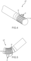
- Figs. 4 and 5 are similar to Figs.1 and 2 , respectively, but depict a tip portion 10 B of a high-density mapping catheter according to a second embodiment.
- circumferential through-cuts 40 define a plurality of discs 42 on which microelectrodes 18 are mounted.
- a helical cut could be used to form the flexible tip configuration shown in Figs. 4 and 5 .
- the microelectrodes 18 are mounted in a nonconductive material such as PEEK.
- FIG. 6 A third embodiment of a tip portion 10 C is depicted in Figs. 6 and 7 .
- the interlocking, dovetailed pattern is formed from conductive material since this is an ablation tip.
- the distal end 44 of this flexible ablation tip includes a pair of symmetrically-placed, high-density microelectrodes 46 for mapping.
- this configuration includes two front-facing irrigation ports 48, and a thermocouple or a temperature sensor 50.
- the mapping electrodes 46 are mounted in a nonconductive insert 52 to electrically insulate these mapping electrodes from the remainder of the ablation tip.
- the flexible ablation tip is 4 millimeters long.
- the pads and pockets defined by the serpentine cuts 54 are smaller than the corresponding pads and pockets depicted in, for example, Figs. 1 and 2 .
- the individual pads 56 do not carry microelectrodes and, therefore, the pads can be smaller in this configuration of the ablation tip than they are in the high-density mapping tips.
- Figs. 8 and 9 depict an ablation tip portion 10° and high-density mapping electrode according to a fourth embodiment.
- This embodiment is a 7.5 Fr catheter having a 4.0 millimeters long, flexible ablation electrode manufactured from, for example, platinum.
- four high-density mapping electrodes 58 are mounted through the distal pads 60 of pad structures.
- each pad structure includes a larger distal pad and a smaller proximal pad 62; and each microelectrode 58 is mounted through an aperture 64 extending through a distal pad 60.
- each of the four mapping electrodes is individually insulated and has its own lead wire (shown in, for example, Figs 5 . And 6) extending from the electrode 58 out the proximal end of the catheter. Similar to what occurs in each of the embodiments already discussed, this is an irrigated configuration.
- irrigant e.g., cooled saline
- irrigant is routed from the proximal end of the catheter, through the catheter shaft, and out of the serpentine gaps formed in the tip.
- Figs. 10-16 provide details concerning the tip portion 10 E of a high-density mapping catheter according to a fifth embodiment.
- this catheter tip 10 E gets its flexibility from a plurality of circumferential, dovetail cuts that define a plurality of serpentine gaps 74 between alternating electrode-carrier bands (or carrier bands) 76 and linking bands 78.
- the working portion of the embodiment 10 E depicted in Fig. 11 is approximately 20 millimeters long (see dimension L in Figs. 11 and 12 ) and has a diameter of 7 Fr to 7.5 Fr (see dimension D in Fig. 11 ).
- the longitudinal electrode spacing between adjacent microelectrode see dimension S L in Figs.
- An end cap 104 may also be present as shown in, for example, Figs. 10 and 11 .
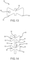
- each carrier band includes a plurality of bowtie-shaped or hourglass-shaped structures 80 (see for example, Figs. 13 and 14 ). Further, in this configuration, each of these bowtie-shaped structures 80 comprises a distal pad 82 and a proximal pad 84, separated by a narrowed region or waist 86. In this configuration, each distal pad 82 of each carrier band 76 has an electrode-mounting aperture 88 (e.g., 0.9 mm diameter) through it.
- electrode-mounting aperture 88 e.g., 0.9 mm diameter
- circumferential connector 90 between each pair of adjacent pad structures.
- the bowtie-shaped or hourglass-shaped pad structures 80 are essentially symmetrical about the waist 86 except for the existence of an electrode-mounting aperture 88 in each of the distal pads 82.
- a distally-opening slot 92 is present between adjacent, distally-extending pads 82.
- a proximally-opening slot 94 is present between adjacent, proximally-extending pads 84.
- the circumferentially-extending pad connectors 90 together with the waists 86 of each pad structure 80, define a carrier band waistline that extends around the circumference of the tip portion 10 E of the catheter.
- each linking band 78 also comprises a connected series of bowtie-shaped structures 96.
- the bowtie-shaped pad structures 96 of the linking bands 78 are larger than the bowtie-shaped pad structures 80 of the carrier bands 76.
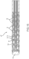
- Figs. 15 and 16 are views with portions of the catheter removed to show inner details of the catheter tip portion of 10 E .
- Fig. 15 it is possible to see the individual lead wires 98 extending longitudinally through the catheter shaft and connecting with each of the microelectrodes 18.
- an internal spring 100 in this figure. This spring helps the tip portion 10 E of the catheter maintain its flexibility, and it helps create the gaps between adjacent carrier bands 76 and linking bands 78.
- Fig. 16 depicts an internal irrigation lumen 102 that acts as an irrigant distribution manifold.
- the button electrodes or microelectrodes 18 may have a diameter between 0.7 and 0.9 millimeters.
- the lead wires extending through the catheter shaft to each of these electrodes may comprise 38 AWG wire.
- an end cap 104 may be metallic, or otherwise radiopaque, to facilitate visualization of the catheter tip during use of a fluoroscope.
- Figs. 17-26 depict aspects of a sixth embodiment of a tip portion 10 F .
- Fig. 17 depicts a cylindrical-shaped portion 106 of nonconductive material that has been laser cut to define an interlocking, but flexible pattern 108 (see Fig. 18).
- Fig. 18 shows what that pattern 108 looks like when it is laid out flat rather than having the cylindrical shape depicted in Fig. 17 .
- a plurality of electrode-carrier bands (or carrier bands) 110 and a plurality of linking bands 112 are present.
- Fig. 19 is similar to Fig. 14 , but shows adjacent pad structures 113 according to the sixth embodiment, as also shown in Figs. 17 and 18 .
- the carrier bands 110 are not completely separate from the adjacent linking bands 112.
- this embodiment includes a plurality of inter-band bridges or connectors 114. All of the bands 110, 112 are thereby loosely interconnected, and one band cannot move completely independently of any other band comprising the working portion of the high-density mapping catheter tip 10 F .
- each pad structure 113 is not the symmetrical bowtie-shaped structure 80 depicted in, for example, Fig. 12 . Rather, in the sixth embodiment, the distal tabs 116 of each pad structure 113 are larger than the corresponding proximal pads 118 of the pad structure 113. The electrode apertures 120 extend through this larger distal pad 116.
- slots are formed between adjacent pad structures 113.
- a relatively shallow, proximally-opening tab slot 122 is formed between adjacent proximal pads 118.
- a relatively deep, distally-opening tab slot 124 is formed between adjacent pairs of distal pads 116.
- circumferentially-extending connectors 126 are again present between adjacent pad structures 113. All of these connectors on a single carrier band 110, together with the waists 128 of each pad structure comprising part of that same carrier band, form a carrier band waistline.
- Fig. 20 depicts a tab structure 130 from a linking band 112.
- Each linking band comprises a plurality of these tab structures.
- Each tab structure includes a relatively-longer, proximally-extending tab (or'proximal tab') 132 in a relatively-shorter, distally-extending tab (or'distal tab') 134.
- Fig. 21 depicts two adjacent tab structures 130 of a single linking band 112.
- a proximally-opening pocket 136 is defined between adjacent proximal tabs 134.
- a distally-opening pocket is defined between adjacent distal tabs.
- each linking band 112 includes a circumferentially-extending proximal edge 142 and a circumferentially-extending distal edge 144.
- the proximal edge defines a series of proximally-extending tabs 132 and proximally-opening pockets 136, and the distal edge 144 of each linking band 112 forms a plurality of distally-extending tabs and distally-opening pockets 138.
- Fig. 22 also relates to the sixth embodiment.
- Fig. 22 depicts a single linking band 112 (on the left) flexibly interlocked with a single carrier band 110 (on the right).
- each proximally-extending tab 132 is flexibly interlocked in a corresponding distally-opening slot 124 in a carrier band 110.
- each distally-extending pad 116 of the carrier band is flexibly interlocked in a corresponding proximally-opening pocket 136 in the linking band 112.
- Each tab structure of the linking band is an asymmetrical bowtie configuration.
- each pad structure 113 of the carrier band 110 is also an asymmetrical bowtie configuration.
- the serpentine gap extending between the linking band 112 and the carrier band 110 e.g., a laser cut gap) defines the tabs and the pockets of the linking band, and define the complementary pads and slots, respectively, of the carrier bands.
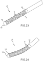
- Fig. 23 depicts a fully-assembled tip portion 10 F of a high-density mapping catheter according to the sixth embodiment.
- the fully assembled tip includes a most-proximal band (or shaft-transition band) 146, and a most-distal band (or end-cap-transition band) 148.
- An end cap 150 may be platinum or some other radiopaque material to facilitate visualization on a fluoroscopy screen.
- the button electrodes or microelectrodes 18 are slightly raised off the outer surface of the laser cut PEEK material. This is also clearly visible in Fig. 24 , which shows the catheter tip in a slightly-flexed configuration.
- mapping electrodes 18 mounted in the laser-cut PEEK material.
- the catheter shaft is 7 Fr or 7.5 Fr.
- Figs. 25 and 26 also depict the sixth embodiment.
- Fig. 25 shows an entire catheter 152, including an electrical connector 154 and a control handle 156 near the proximal portion of the catheter and a flexible high-density mapping tip 10 F at the distal end of the catheter 152.
- Fig. 26 is an enlarged view of the circled portion of Fig. 25 .
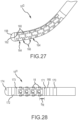
- Fig. 27 depicts the distal tip portion 10 G of a high-density mapping catheter according to a seventh embodiment. Similar to some of the configurations discussed above, this tip portion includes a metallic cap (e.g., a platinum cap) 158 or otherwise radiopaque cap to facilitate visualization on fluoroscopy.
- This specific embodiment 10 G is different from the embodiment 10 F depicted, for example, in Fig. 23 , since the electrode apertures 160 in this embodiment are located through the distal pads 162 of pad structures of electrode carrier bands 164 that are relatively smaller than the tab structures of the linking bands 166.
- each electrode-carrier band 164 includes a plurality of bowtie-shaped pad structures that are circumferentially arranged around the longitudinal axis of the catheter.
- each linking band 166 comprises a plurality of bowtie-shaped tab structures also arranged circumferentially around the catheter longitudinal axis.
- the bowtie-shaped tab structures are relatively larger than the bowtie-shaped pad structures of the electrode-carrier bands 164.
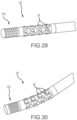
- Fig. 28 depicts an eighth embodiment of a high-density mapping tip portion 10 H .
- a 7 Fr catheter includes a flexible array of microelectrodes 18 that is similar to, but shorter than, the flexible array of microelectrodes depicted in, for example, Figs. 23-26 .
- 1.0 mm ring electrodes 168, 170, 172 are located at each longitudinal end of the flexible array of 0.9 mm diameter microelectrodes 18.
- the most-proximal circumferential ring of microelectrodes 18 is located approximately 1.2 mm (see dimension S R in Fig. 28 ) from the most-proximal circumferential edge 171 of array.
- microelectrodes there are sixteen microelectrodes arranged in four longitudinally-extending rows of four electrodes, each row radially offset from the next row by 90°.
- the longitudinal spacing between adjacent microelectrodes may be, for example, 1.8 mm.
- 1.0 mm ring electrode 172 located distal of the most-distal edge 173 of the flexible array of microelectrodes.
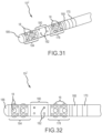
- Figs. 29 and 30 depict the distal portion 10 I of a map-and-ablate catheter according to a ninth embodiment. Similar to what is shown in Fig. 28 , the ninth embodiment shown in Figs. 29 and 30 includes a flexible array of microelectrodes 18 comprising sixteen microelectrodes arranged in four longitudinally extending rows of four where each of these rows is radially offset by 90° from the next adjacent row of electrodes. In this embodiment, however, the most-distal end of the catheter comprises a flexible ablation tip 176.
- This ablation tip may be, for example, a Cool Flex TM ablation tip sold by St. Jude Medical, Inc. of St. Paul, Minnesota.
- irrigant would flow down the catheter shaft and exit through the serpentine gaps in the flexible array of microelectrodes and through the openings in the flexible ablation tip. This tip would advantageously conform to the cardiac tissue during both mapping and ablation procedures.
- Figs. 31 and 32 depict a tip portion 10 J of a map-and-ablate catheter according to a tenth embodiment.
- two 1.0 mm ring electrodes are encountered, including a most-proximal ring 170 electrode and a most-distal ring electrode 168.
- this short flexible array of microelectrodes Connected to the distal-side of this short flexible array of microelectrodes is an ablation region 180 that is approximately 3.5 mm long and that includes a plurality of irrigation holes 182. Distal of the ablation region is another, rather short flexible array 184 of microelectrodes. In this particular configuration, the distal flexible array 184 of microelectrodes is similar to the proximal, flexible array 178 of microelectrodes. Finally, in this map ablate catheter, the distal end includes a metallic cap 186 that may be used for mapping, ablation, and/or visualization on fluoroscopy.
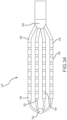
- Figs. 33-37 depict a tip portion 10 K comprising a flexible array of microelectrodes according to an eleventh embodiment.
- This planar array (or 'paddle' configuration) of microelectrodes comprises four side-by-side, longitudinally-extending arms 188, 190, 192, 194 forming the flexible framework on which the thirty-two 1.0 mm long x 0.8 mm diameter ring electrodes 196 are carried.
- a few of these ring electrodes may be slightly longer.
- the four ring-electrode-carrier arms comprise a first outboard arm 188, a second outboard arm 190, a first inboard arm 192, and a second inboard arm 194. These arms are laterally separated from each other by approximately 3.3 mm in this embodiment.
- Each of the four arms carries eight small ring electrodes 196, spaced along its length. In the depicted embodiment, these small ring-shaped microelectrodes are longitudinally separated from each other by approximately 1.0 mm.
- each of the paddle catheters depicted in Figs. 33-42 shows four arms, the paddle could comprise more or fewer arms.
- Fig. 33 is an isometric, fragmentary view of the planar array.
- the most-distal ring electrode on the first outboard arm 188 is slightly enlarged as is the most-proximal ring electrode 220 on the second outboard arm 190.
- These slightly enlarged electrodes 198, 200 e.g., in the depicted embodiment, these microelectrodes are slightly longer than the other ring electrodes) can be used, for example, for more precise localization of the flexible array in mapping and navigation systems.
- This distal member may be constructed from metal or some other radiopaque material to provide fluoroscopy visualization and semi-independent planar movement between the outer and inner arms.
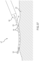
- the planar, flexible arms conform to trabeculated tissue 204, enabling a physician to maintain contact between several of the electrodes and the tissue. This enhances the accuracy, and the corresponding diagnostic value, of the recorded information concerning the heart's electrical activity.
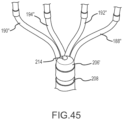
- Figs. 38 and 39 depict a flexible array of microelectrodes at the tip portion 10 L of a high-density mapping catheter according to a twelfth embodiment.
- there are four 1.0 mm ring electrodes (depicted with a 2.0 mm longitudinal spacing) mounted on the distal end of the catheter shaft, proximal to a proximal bushing 206 and to the proximal ends of ring electrode carrier arms 188', 190', 192', 194'.
- each of the four electrode carrying arms has eight small ring electrodes 196 (microelectrodes) mounted on it.
- the four arms are designed to maintain the thirty-two small ring electrodes in a spaced relationship so that each small ring electrode can capture separate data about the electrical activity of the cardiac tissue adjacent to the microelectrodes.
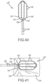
- Figs. 40-42 depict two variations 10 M , 10 N of a similar tip portion comprising a flexible array of microelectrodes 196'.
- These small ring electrodes (1.0 mm long x 0.8 mm diameter) are longitudinally separated from each other by approximately 3.0 mm in this embodiment, and the electrode carrying arms are laterally separated from each other by approximately 4.0 mm.
- the high-density mapping catheter also includes two tethers 210 extending transverse across and interconnecting the four electrode carrying arms. Although two tethers are shown in Fig. 42 , any number of tethers could be used, including a single tether.
- the tether or tethers 210 help maintain a predictable relationship between the electrode carrying arms 188", 190", 192", 194" by controlling, for example, how each electrode carrying arm may move relative to the other electrode carrying arms.
- Each tether 210 may comprise a tensile element, such as slender mono- or multi-filament nylon thread or suture-like material.
- the tethers may be connected with or to the electrode carrying arm in a variety of ways. In Fig.
- the tethers 210 have been adhered or ultrasonically welded to each of the electrode carrying arms 188", 190", 192", 194".
- a tether could be tied to or looped around the arms. Reflowing the device during the manufacturing process may allow the tether or tethers to become incorporated into the arms polymer insulation, thereby securing the tether to the arms and minimizing the need for tying, looping, gluing, or otherwise attaching the tethers to the arms.
- the tethers 210 are configured to also collapse or fold during insertion of the catheter into a delivery sheath or introducer.
- Fig. 43 depicts yet another embodiment of a tip portion 10° comprising a flexible array of microelectrodes. This configuration is most similar to the first variation 10 M of the thirteenth embodiment, which is depicted in Figs. 40 and 41 . However, in the fourteenth embodiment, there are two additional ring electrodes 212 mounted near the distal end of each outboard arm.
- Fig. 44 depicts an alternative variation of the high-density mapping catheter embodiment 108 depicted in Fig. 43 .
- an irrigation port 214 is present at the distal end of a proximal bushing 206', and the irrigation port is positioned to deliver irrigant to or near the point where the electrode carrying arms exit from the distal end of the proximal bushing that is mounted on the distal end of the catheter shaft in this embodiment.
- a second irrigation port may be located near the distal intersection of the electrode carrying arms.
- multiple irrigation ports could be present at various positions along the electrode carrying arms 188", 190", 192", 194".
- irrigation port 214 is an enlarged, fragmentary view of the irrigation port 214 on the proximal bushing 206'.
- multiple irrigation ports could be present on the proximal bushing (e.g., one or more on each side of the planar array of microelectrodes) to provide more uniform irrigant distribution at or near the proximal apex of the arms 188", 190", 192", 194".
- a distal irrigation port set (not shown) comprising multiple ports could be included at or near the distal apex of the arms 188", 190", 192", 194".
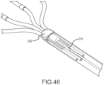
- Fig. 46 is a fragmentary, isometric view of the distal portion of the catheter shaft of a high-density mapping catheter. In this view, portions of the catheter shaft have been removed to reveal a sensor 216 located just proximal to the proximal bushing.
- sensors may be incorporated at this location, or at similar locations, in the high-density mapping catheters described herein. These sensors may be mounted in the catheter shaft, as shown in Fig. 46 , or they may be mounted at other locations (e.g., along the electrode carrying arms of the high-density mapping paddle and/or at the distal apex or joint of the tip portion).
- the sensor 216 is a magnetic field sensor configured for use with an electromagnetic localization system such as the MediGuide TM System sold by St. Jude Medical, Inc. of St. Paul, Minnesota.
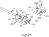
- Fig. 47 is an exploded, isometric view of one embodiment of a delivery adapter 218 designed to facilitate delivery of a paddle catheter into and through a guiding sheath or introducer 220 having a circular cross section.
- the delivery adapter 218 comprises a first portion 218A having pins 222 extending therefrom, and a second portion 218B having complementary pin-receiving holes 224 therein.
- a proximal pocket configured to support or hold the distal end of a dilator hub 228 (labeled in Figs. 48A and 48B ) is formed.
- the first portion 218A of the delivery adapter includes a first part 226A of that pocket
- the second portion 218B of the delivery adapter comprises a second part 226B of the pocket
- a dilator shaft channel is also present and comprises a first trough 230A formed in the first portion 218A of the delivery adapter 218 and a second trough 230B formed in the second portion 218B of the delivery adapter 218.
- the distal side of the delivery adapter in this embodiment, comprises a threaded hole (e.g., a female luer lock) 232A, 232B adapted to thread onto a shaft or fitting (e.g., a male luer lock) 234 extending proximally from the proximal end of the guiding sheath 220.
- a threaded hole e.g., a female luer lock
- 232B adapted to thread onto a shaft or fitting (e.g., a male luer lock) 234 extending proximally from the proximal end of the guiding sheath 220.
- the interior of the delivery adapter between the proximal pocket 226A, 226B and the threaded hole 232A, 232B defines a hollow compression or folding cone 236A, 236B.
- the lateral cross-sectional shape of the proximal end of this compression cone is elliptical or nearly elliptical, and the lateral cross-sectional shape of the distal-most portion of the compression cone is circular or near circular, matching the channel through a hub 238 of the guiding sheath 220.
- the compression cone is thereby configured or adapted to compress the relatively flat paddle of the high-density mapping catheter into a configuration having a substantially circular cross-sectional shape or other shape that fits into the proximal opening in the guiding sheath hub 238.
- the delivery adapter may be splittable for easy removal when used with a splittable guiding sheath.
- a dilator 240 is inserted into and through the delivery adapter 218 and seated in the pocket 226A, 226B formed in the proximal side of the assembled delivery adapter.
- the assembled delivery adapter 218, with the dilator 240 in place, is then mounted to the guiding sheath 220 as shown in Fig. 48A .
- the dilator 240, shown by itself in Fig. 48B is then removed from the delivery adapter 218 and guiding sheath 220, as may be seen in the lefthand portion of Fig. 48C .
- the paddle 242 of a high-density mapping catheter is inserted into the proximal end of the compression cone 236A, 236B of the delivery adapter.
- the electrode carrying arms of the paddle have been inserted further into the compression cone. As the electrode carrying arms of the panel impact the angled side surfaces of the compression cone formed in the delivery adapter 218, the electrode carrying arms are compressed towards each other.
- the paddle When the arms have been sufficiently compressed together (i.e., into a side-by-side, touching or near-touching configuration), the paddle then fits into the proximal end of the port through the guiding sheath or introducer 220 and may be pushed through the hemostasis valve (not shown) in the hub 238 at the proximal end of the guiding sheath 220.
- the electrode carrying arms As shown in Fig. 48E , as the paddle portion 242 of the high-density mapping catheter exits from the distal end of the guiding sheath 220, the electrode carrying arms comprising the paddle remain compressed together. Once the electrode carrying arms of the paddle exit from the distal end of the shaft or tube of the guiding sheath, the electrode carrying arms expand back into the paddle configuration, as best shown in Fig. 48F .
- one or more of the ring electrodes 208 could be used to send pacing signals to, for example, cardiac tissue.
- the arms (or the understructure of the arms) comprising the paddle structure (or multi-arm, electrode-carrying, flexible framework) at the distal end of the catheters depicted in Figs. 33-46 are preferably constructed from a flexible or spring-like material such as Nitinol.
- the construction (including, for example, the length and/or diameter of the arms) and material of the arms can be adjusted or tailored to be created, for example, desired resiliency, flexibility, foldability, conformability, and stiffness characteristics, including one or more characteristics that may vary from the proximal end of a single arm to the distal end of that arm, or between or among the plurality of arms comprising a single paddle structure.
- the foldability of materials such as Nitinol provide the additional advantage of facilitating insertion of the paddle structure into a delivery catheter or introducer, whether during delivery of the catheter into the body or removal of the catheter from the body at the end of a procedure.
- a short guide sheath 220 (used, for example, for epicardial access) is depicted in Figs. 47 and 48A-48F
- a longer guide sheath used, for example, to access the heart from a femoral access point) could be used to introduce the flexible high-density mapping and ablation tips described herein.
- the disclosed catheters are useful to (1) define regional propagation maps on one centimeter square areas within the atrial walls of the heart; (2) identify complex fractionated atrial electrograms for ablation; (3) identify localized, focal potentials between the microelectrodes for higher electrogram resolution; and/or (4) more precisely target areas for ablation.
- These mapping catheters and ablation catheters are constructed to conform to, and remain in contact with, cardiac tissue despite potentially erratic cardiac motion. Such enhanced stability of the catheter on a heart wall during cardiac motion provides more accurate mapping and ablation due to sustained tissue-electrode contact.
- the catheters described herein may be useful for epicardial and/or endocardial use.
- planar array embodiments depicted in Figs. 33-48F may be used in an epicardial procedure where the planar array of microelectrodes is positioned between the myocardial surface and the pericardium.
- planar array embodiments may be used in an endocardial procedure to quickly sweep and/or analyze the inner surfaces of the myocardium and quickly create high-density maps of the heart tissue's electrical properties.
- proximal and distal may be used throughout the specification with reference to a clinician manipulating one end of an instrument used to treat a patient.
- proximal refers to the portion of the instrument closest to the clinician and the term “distal” refers to the portion located furthest from the clinician.
- distal refers to the portion located furthest from the clinician.
- spatial terms such as “vertical,” “horizontal,” “up,” and “down” may be used herein with respect to the illustrated embodiments.
- surgical instruments may be used in many orientations and positions, and these terms are not intended to be limiting and absolute.
Landscapes
- Health & Medical Sciences (AREA)
- Life Sciences & Earth Sciences (AREA)
- Engineering & Computer Science (AREA)
- Animal Behavior & Ethology (AREA)
- Veterinary Medicine (AREA)
- Public Health (AREA)
- Biomedical Technology (AREA)
- General Health & Medical Sciences (AREA)
- Heart & Thoracic Surgery (AREA)
- Surgery (AREA)
- Molecular Biology (AREA)
- Medical Informatics (AREA)
- Physics & Mathematics (AREA)
- Pathology (AREA)
- Biophysics (AREA)
- Nuclear Medicine, Radiotherapy & Molecular Imaging (AREA)
- Cardiology (AREA)
- Radiology & Medical Imaging (AREA)
- Neurology (AREA)
- Neurosurgery (AREA)
- Orthopedic Medicine & Surgery (AREA)
- Pain & Pain Management (AREA)
- Otolaryngology (AREA)
- Plasma & Fusion (AREA)
- Physiology (AREA)
- Surgical Instruments (AREA)
- Measurement And Recording Of Electrical Phenomena And Electrical Characteristics Of The Living Body (AREA)
- Electrotherapy Devices (AREA)
- Media Introduction/Drainage Providing Device (AREA)
Claims (15)
- Hochdichter Mapping-Katheter, der folgendes umfasst:einen Katheterschaft, der ein proximales Ende und ein distales Ende umfasst, wobei der Katheterschaft eine Katheterschaft-Längsachse definiert, die sich zwischen dem proximalen Ende und dem distalen Ende erstreckt;einen flexiblen Spitzenabschnitt, der neben dem distalen Ende des Katheterschafts angeordnet ist, wobei der flexible Spitzenabschnitt einen flexiblen Rahmen mit einem nichtleitenden Material umfasst; undeine Vielzahl von Mikroelektroden (196), die auf dem flexiblen Rahmen befestigt ist und eine flexible Anordnung von Mikroelektroden bildet, die geeignet sind, sich dem Gewebe anzupassen, wobei die Mikroelektroden (196) Ringelektroden sind; wobei der flexible Rahmen konfiguriert ist, um eine relative Bewegung unter zumindest einigen der Mikroelektroden (196) relativ zu anderen der Mikroelektroden (196) zu ermöglichen; und wobei das nichtleitende Material jede Mikroelektrode von anderen Mikroelektroden (196) isoliert;wobei die Vielzahl von Mikroelektroden (106) auf dem flexiblen Rahmen befestigt ist und in einer Vielzahl von Gruppen angeordnet ist;wobei jede Gruppe der Vielzahl von Gruppen von Mikroelektroden (196) eine Reihe von in Längsrichtung ausgerichteten Mikroelektroden umfasst, die parallel zu der Längsachse des Katheterschafts ausgerichtet sind;wobei die flexible Anordnung von Mikroelektroden (196) eine zweiseitige planare Anordnung von Mikroelektroden umfasst, wobei die Mikroelektroden konfiguriert sind, um Gewebe auf einer Vorderseite und Rückseite der planaren Anordnung zu berühren; wobei der flexible Rahmen eine Vielzahl von sich in Längsrichtung erstreckenden und seitlich getrennten Armen (190, 192, 194, 188) umfasst, die sich parallel zur Längsachse des Katheterschafts erstrecken, und in einer Ebene liegen; wobei jeder sich in Längsrichtung erstreckende Arm (190, 192, 194, 188) eine Gruppe der Vielzahl von Gruppen von Mikroelektroden (196) aufweist, die auf diesem verteilt und angeordnet sind; wobei eine proximale Buchse (206) auf dem distalen Ende des Katheterschafts befestigt ist; wobei jeder sich in Längsrichtung erstreckende Arm ein distales Ende der proximalen Buchse (206) verlässt; undwobei die Vielzahl von sich in Längsrichtung erstreckenden Armen (190, 192, 194, 188) konfiguriert ist, die Vielzahl von Mikroelektroden (196) in der Vielzahl von Reihen in beabstandeter Beziehung zueinander zu halten, so dass jede der Vielzahl von Mikroelektroden (196) separate Daten über die elektrische Aktivität von Herzgewebe benachbart der Vielzahl von Mikroelektroden (196) erfassen kann.
- Hochdichter Mapping-Katheter nach Anspruch 1, wobei die proximale Buchse weiter einen Spülanschluss umfasst, der geeignet ist, eine Spülflüssigkeit an einen Abschnitt der sich in Längsrichtung erstreckenden Arme (190, 192, 194, 188) zu liefern.
- Hochdichter Mapping-Katheter nach Anspruch 1 oder Anspruch 2, wobei die Vielzahl von sich in Längsrichtung erstreckenden Armen (190, 192, 194, 188) vier nebeneinander angeordnete Arme umfasst, die einen ersten äußeren Arm, einen zweiten äußeren Arm, einen ersten inneren Arm und einen zweiten inneren Arm einschließen.
- Hochdichter Mapping-Katheter nach einem der vorhergehenden Ansprüche, wobei die Mikroelektroden (196), die die Vielzahl von Mikroelektroden umfassen, alle die gleiche Größe aufweisen.
- Hochdichter Mapping-Katheter nach einem der vorhergehenden Ansprüche, der weiter mindestens eine Fixierung umfasst, die an mindestens zwei Armen der Vielzahl von sich in Längsrichtung erstreckenden Armen (190, 192, 194, 188) befestigt ist.
- Hochdichter Mapping-Katheter nach einem der vorhergehenden Ansprüche, wobei die Vielzahl von Mikroelektroden (196) zwischen vier und vierundsechzig individuelle Mikroelektroden umfasst.
- Hochdichter Mapping-Katheter nach einem der vorhergehenden Ansprüche, wobei ein separater elektrischer Zuleitungsdraht mit jeder Mikroelektrode der Vielzahl von Mikroelektroden (196) elektrisch verbunden ist.
- Hochdichter Mapping-Katheter nach einem der vorhergehenden Ansprüche, wobei die Vielzahl der in Längsrichtung ausgerichteten Arme (190, 192, 194, 188) einen ersten äußeren Arm (188), einen zweiten äußeren Arm (190), einen ersten inneren Arm (192) und einen zweiten inneren Arm (194) aufweist; und wobei der erste äußere Arm (188) eine distalste Mikroelektrode (198) und der zweite äußere Arm eine proximalste Elektrode (200) aufweist, wobei die distalste Elektrode (198) und die proximalste Elektrode (200) geringfügig länger sind als die anderen Mikroelektroden (196), um eine präzisere Lokalisierung der flexiblen Anordnung in Mapping- und Navigationssystemen zu ermöglichen.
- Hochdichter Mapping-Katheter nach Anspruch 8, wobei das Paar geringfügig längerer Mikroelektroden (198, 200) symmetrisch positioniert ist und an diametral entgegengesetzten Ecken der planaren Anordnung von Mikroelektroden angeordnet ist.
- Hochdichter Mapping-Katheter nach einem der vorhergehenden Ansprüche, der weiter in inneres Spüllumen umfasst.
- Hochdichter Mapping-Katheter nach einem der vorhergehenden Ansprüche, wobei die sich in Längsrichtung erstreckenden Arme (190, 192, 194, 188) an einem distalen Element (202) in der Nähe eines distalen Endes des flexiblen Spitzenabschnitts zusammenlaufen.
- Hochdichter Mapping-Katheter nach einem der vorhergehenden Ansprüche, wobei der flexible Rahmen mehr als vier sich in Längsrichtung erstreckende Arme umfasst.
- Hochdichter Mapping-Katheter nach einem der vorhergehenden Ansprüche, wobei die sich in Längsrichtung erstreckenden Arme oder ein Unterbau der sich in Längsrichtung erstreckenden Arme aus Nitinol aufgebaut sind.
- Hochdichter Mapping-Katheter nach einem der vorhergehenden Ansprüche, wobei zumindest ein Arm eine oder mehrere Eigenschaften aufweist, die sich von dem proximalen Ende eines einzelnen Arms zu dem distalen Ende dieses Arms verändern, wobei die Eigenschaften eine oder mehrere der folgenden umfassen: Resilienz, Flexibilität, Faltbarkeit, Anpassungsfähigkeit und Steifigkeit.
- Hochdichter Mapping-Katheter nach einem der vorhergehenden Ansprüche, wobei zumindest ein Arm eine oder mehrere Eigenschaften aufweist, die sich von einem anderen Arm unterscheiden, wobei die Eigenschaften eine oder mehrere der folgenden umfassen: Resilienz, Flexibilität, Faltbarkeit, Anpassungsfähigkeit und Steifigkeit.
Applications Claiming Priority (5)
| Application Number | Priority Date | Filing Date | Title |
|---|---|---|---|
| US201361753429P | 2013-01-16 | 2013-01-16 | |
| EP20158596.5A EP3679861B1 (de) | 2013-01-16 | 2014-01-16 | Flexible hochdichte mapping-katheterspitzen und flexible ablationskatheterspitzen mit integrierten hochdichten mapping-elektroden |
| EP20180888.8A EP3738508B1 (de) | 2013-01-16 | 2014-01-16 | Flexible hochdichte mappingkatheterspitzen und flexible ablationskatheterspitzen mit integrierten hochdichten mappingelektroden |
| PCT/US2014/011940 WO2014113612A1 (en) | 2013-01-16 | 2014-01-16 | Flexible high-density mapping catheter tips and flexible ablation catheter tips with onboard high-density mapping electrodes |
| EP14703679.2A EP2908723B1 (de) | 2013-01-16 | 2014-01-16 | Flexible katheterspitzen für mapping von hoher dichte und ablationskatheterspitzen mit mappingelektroden von hoher dichte |
Related Parent Applications (4)
| Application Number | Title | Priority Date | Filing Date |
|---|---|---|---|
| EP20180888.8A Division-Into EP3738508B1 (de) | 2013-01-16 | 2014-01-16 | Flexible hochdichte mappingkatheterspitzen und flexible ablationskatheterspitzen mit integrierten hochdichten mappingelektroden |
| EP20180888.8A Division EP3738508B1 (de) | 2013-01-16 | 2014-01-16 | Flexible hochdichte mappingkatheterspitzen und flexible ablationskatheterspitzen mit integrierten hochdichten mappingelektroden |
| EP14703679.2A Division EP2908723B1 (de) | 2013-01-16 | 2014-01-16 | Flexible katheterspitzen für mapping von hoher dichte und ablationskatheterspitzen mit mappingelektroden von hoher dichte |
| EP20158596.5A Division EP3679861B1 (de) | 2013-01-16 | 2014-01-16 | Flexible hochdichte mapping-katheterspitzen und flexible ablationskatheterspitzen mit integrierten hochdichten mapping-elektroden |
Publications (2)
| Publication Number | Publication Date |
|---|---|
| EP4101372A1 EP4101372A1 (de) | 2022-12-14 |
| EP4101372B1 true EP4101372B1 (de) | 2024-12-25 |
Family
ID=50071746
Family Applications (6)
| Application Number | Title | Priority Date | Filing Date |
|---|---|---|---|
| EP20180888.8A Revoked EP3738508B1 (de) | 2013-01-16 | 2014-01-16 | Flexible hochdichte mappingkatheterspitzen und flexible ablationskatheterspitzen mit integrierten hochdichten mappingelektroden |
| EP23198506.0A Pending EP4272631A3 (de) | 2013-01-16 | 2014-01-16 | Flexible hochdichte mapping-katheterspitzen und flexible ablationskatheterspitzen mit integrierten hochdichten mapping-elektroden |
| EP22188371.3A Active EP4101372B1 (de) | 2013-01-16 | 2014-01-16 | Flexible hochdichte mappingkatheterspitzen und flexible ablationskatheterspitzen mit integrierten hochdichten mappingelektroden |
| EP14703679.2A Active EP2908723B1 (de) | 2013-01-16 | 2014-01-16 | Flexible katheterspitzen für mapping von hoher dichte und ablationskatheterspitzen mit mappingelektroden von hoher dichte |
| EP20158596.5A Active EP3679861B1 (de) | 2013-01-16 | 2014-01-16 | Flexible hochdichte mapping-katheterspitzen und flexible ablationskatheterspitzen mit integrierten hochdichten mapping-elektroden |
| EP20183495.9A Revoked EP3738509B1 (de) | 2013-01-16 | 2014-01-16 | Flexible hochdichte mappingkatheterspitzen und flexible ablationskatheterspitzen mit integrierten hochdichten mappingelektroden |
Family Applications Before (2)
| Application Number | Title | Priority Date | Filing Date |
|---|---|---|---|
| EP20180888.8A Revoked EP3738508B1 (de) | 2013-01-16 | 2014-01-16 | Flexible hochdichte mappingkatheterspitzen und flexible ablationskatheterspitzen mit integrierten hochdichten mappingelektroden |
| EP23198506.0A Pending EP4272631A3 (de) | 2013-01-16 | 2014-01-16 | Flexible hochdichte mapping-katheterspitzen und flexible ablationskatheterspitzen mit integrierten hochdichten mapping-elektroden |
Family Applications After (3)
| Application Number | Title | Priority Date | Filing Date |
|---|---|---|---|
| EP14703679.2A Active EP2908723B1 (de) | 2013-01-16 | 2014-01-16 | Flexible katheterspitzen für mapping von hoher dichte und ablationskatheterspitzen mit mappingelektroden von hoher dichte |
| EP20158596.5A Active EP3679861B1 (de) | 2013-01-16 | 2014-01-16 | Flexible hochdichte mapping-katheterspitzen und flexible ablationskatheterspitzen mit integrierten hochdichten mapping-elektroden |
| EP20183495.9A Revoked EP3738509B1 (de) | 2013-01-16 | 2014-01-16 | Flexible hochdichte mappingkatheterspitzen und flexible ablationskatheterspitzen mit integrierten hochdichten mappingelektroden |
Country Status (5)
| Country | Link |
|---|---|
| US (14) | US20140200639A1 (de) |
| EP (6) | EP3738508B1 (de) |
| JP (3) | JP6050522B2 (de) |
| CN (1) | CN104968261B (de) |
| WO (1) | WO2014113612A1 (de) |
Families Citing this family (79)
| Publication number | Priority date | Publication date | Assignee | Title |
|---|---|---|---|---|
| JP3245806B2 (ja) | 1994-04-14 | 2002-01-15 | 新日本製鐵株式会社 | フェライト系ステンレス鋼の製造方法 |
| EP2819604A1 (de) * | 2012-03-01 | 2015-01-07 | Boston Scientific Scimed, Inc. | Off-wall-kontaktelektrodenvorrichtungen sowie verfahren zur nervenmodulation |
| US20140200639A1 (en) | 2013-01-16 | 2014-07-17 | Advanced Neuromodulation Systems, Inc. | Self-expanding neurostimulation leads having broad multi-electrode arrays |
| US9808171B2 (en) | 2013-05-07 | 2017-11-07 | St. Jude Medical, Atrial Fibrillation Division, Inc. | Utilization of electrode spatial arrangements for characterizing cardiac conduction conditions |
| EP3062688B1 (de) * | 2013-12-20 | 2019-01-16 | St. Jude Medical, Cardiology Division, Inc. | Koaxiale elektrodenkatheter zur extraktion elektrophysiologischer parameter |
| US10136829B2 (en) | 2014-02-25 | 2018-11-27 | St. Jude Medical, Cardiology Division, Inc. | Systems and methods for using electrophysiology properties for classifying arrhythmia sources |
| JP6336620B2 (ja) | 2014-05-06 | 2018-06-06 | セント・ジュード・メディカル,カーディオロジー・ディヴィジョン,インコーポレイテッド | 電極支持構造アセンブリ |
| US10118022B2 (en) | 2014-06-05 | 2018-11-06 | St. Jude Medical, Cardiology Division, Inc. | Deflectable catheter shaft section |
| US9844645B2 (en) | 2014-06-17 | 2017-12-19 | St. Jude Medical, Cardiology Division, Inc. | Triple coil catheter support |
| US10898096B2 (en) | 2014-10-27 | 2021-01-26 | St. Jude Medical, Cardiology Division, Inc. | Apparatus and method for connecting elements in medical devices |
| US9820664B2 (en) * | 2014-11-20 | 2017-11-21 | Biosense Webster (Israel) Ltd. | Catheter with high density electrode spine array |
| EP3191003B1 (de) * | 2015-01-07 | 2021-09-29 | St. Jude Medical, Cardiology Division, Inc. | Ablationskatheter mit elektroden |
| EP3209235B1 (de) | 2015-01-28 | 2019-06-26 | St. Jude Medical, Cardiology Division, Inc. | Wärmeabbildungskatheter |
| US10602983B2 (en) | 2015-05-08 | 2020-03-31 | St. Jude Medical International Holding S.À R.L. | Integrated sensors for medical devices and method of making integrated sensors for medical devices |
| JP6774967B2 (ja) | 2015-05-12 | 2020-10-28 | セント・ジュード・メディカル,カーディオロジー・ディヴィジョン,インコーポレイテッド | 向きに依存しない感知のためのシステムおよびシステムの作動方法 |
| US10537259B2 (en) | 2015-06-29 | 2020-01-21 | Biosense Webster (Israel) Ltd. | Catheter having closed loop array with in-plane linear electrode portion |
| US9949656B2 (en) | 2015-06-29 | 2018-04-24 | Biosense Webster (Israel) Ltd. | Catheter with stacked spine electrode assembly |
| CN106308921A (zh) * | 2015-06-30 | 2017-01-11 | 四川锦江电子科技有限公司 | 一种具有压力检测的消融装置 |
| US10575742B2 (en) | 2015-06-30 | 2020-03-03 | Biosense Webster (Israel) Ltd. | Catheter having closed electrode assembly with spines of uniform length |
| JP6641003B2 (ja) * | 2015-10-21 | 2020-02-05 | セント・ジュード・メディカル,カーディオロジー・ディヴィジョン,インコーポレイテッド | 高密度電極マッピングカテーテル |
| EP3340916B1 (de) | 2015-10-21 | 2020-12-02 | St. Jude Medical, Cardiology Division, Inc. | Hochdichter elektrodenmapping-katheter |
| WO2017087675A1 (en) * | 2015-11-20 | 2017-05-26 | Cardiac Pacemakers, Inc. | Delivery devices and methods for leadless cardiac devices |
| EP3359073B1 (de) | 2015-11-20 | 2020-02-12 | St. Jude Medical, Cardiology Division, Inc. | Ablatorspitze mit mehreren elektroden mit fähigkeiten zur doppelmodalen, omnidirektionalen rückmeldung |
| CN105411564B (zh) * | 2016-01-20 | 2018-11-20 | 弦普智能科技无锡有限公司 | 一种检测生物电的电极 |
| AU2017214317B2 (en) | 2016-02-05 | 2019-08-22 | Boston Scientfic Neuromodulation Corporation | Implantable optical stimulation lead |
| EP4179991B1 (de) * | 2016-05-03 | 2024-04-24 | St. Jude Medical, Cardiology Division, Inc. | Bewässerter hochdichter elektrodenkatheter |
| CN105919589B (zh) * | 2016-05-27 | 2018-12-18 | 深圳市惠泰医疗器械有限公司 | 带传感器的头端具有盘状螺旋结构的磁定位环状标测电极导管 |
| CN109475316B (zh) * | 2016-06-22 | 2022-05-10 | 圣犹达医疗用品心脏病学部门有限公司 | 用于电生理程序的系统和方法 |
| US10702177B2 (en) | 2016-08-24 | 2020-07-07 | Biosense Webster (Israel) Ltd. | Catheter with bipole electrode spacer and related methods |
| US11039882B2 (en) * | 2016-10-14 | 2021-06-22 | St. Jude Medical, Cardiology Division, Inc. | Ablation catheter with internally fixed subelectrodes |
| WO2018080985A1 (en) | 2016-10-24 | 2018-05-03 | St. Jude Medical, Cardiology Division, Inc. | Catheter insertion devices |
| US11172858B2 (en) | 2016-10-28 | 2021-11-16 | St. Jude Medical, Cardiology Division, Inc. | Flexible high-density mapping catheter |
| CN110177494A (zh) | 2017-01-19 | 2019-08-27 | 圣犹达医疗用品心脏病学部门有限公司 | 鞘可视化 |
| WO2018191686A1 (en) | 2017-04-14 | 2018-10-18 | St. Jude Medical, Cardiology Division, Inc. | Orientation independent sensing, mapping, interface and analysis systems and methods |
| CN106974724B (zh) * | 2017-04-24 | 2019-12-03 | 四川锦江电子科技有限公司 | 一种具有压力检测功能的消融导管 |
| CN110753526B (zh) * | 2017-06-19 | 2023-06-09 | 圣犹达医疗用品心脏病学部门有限公司 | 用于在医疗手术期间高密度感测和消融的器械 |
| US11433220B2 (en) * | 2017-07-07 | 2022-09-06 | St. Jude Medical, Cardiology Division, Inc. | Layered high density electrode mapping catheter |
| CN107198522B (zh) * | 2017-07-18 | 2024-05-03 | 中国人民解放军总医院第一附属医院 | 一种用于记录脑深部信号的复合型电极 |
| US11647935B2 (en) | 2017-07-24 | 2023-05-16 | St. Jude Medical, Cardiology Division, Inc. | Masked ring electrodes |
| JP6936919B2 (ja) * | 2017-10-13 | 2021-09-22 | セント・ジュード・メディカル,カーディオロジー・ディヴィジョン,インコーポレイテッド | 高密度マッピング電極を有するカテーテル |
| US10434312B2 (en) | 2017-11-03 | 2019-10-08 | Amitabh Goel | Electrode assembly for spinal cord stimulation |
| WO2019108664A2 (en) | 2017-11-28 | 2019-06-06 | St. Jude Medical, Cardiology Division, Inc. | Controllable expandable catheter |
| JP6765160B2 (ja) * | 2017-12-11 | 2020-10-07 | 日本ライフライン株式会社 | 焼灼用針装置および腫瘍の高周波焼灼治療システム |
| EP3731747B1 (de) * | 2018-03-13 | 2023-11-01 | St. Jude Medical, Cardiology Division, Inc. | Variable dichte abbildender katheter |
| US11524174B2 (en) | 2018-03-23 | 2022-12-13 | Boston Scientific Neuromodulation Corporation | Optical stimulation system with on-demand monitoring and methods of making and using |
| US11565131B2 (en) | 2018-03-23 | 2023-01-31 | Boston Scientific Neuromodulation Corporation | Optical stimulation systems with calibration and methods of making and using |
| CN112040861B (zh) | 2018-04-05 | 2024-09-17 | 圣犹达医疗用品心脏病学部门有限公司 | 高密度电极标测导管 |
| EP3773301B1 (de) | 2018-04-13 | 2024-03-06 | Karl Storz SE & Co. KG | Führungssystem und dazugehöriges computerprogramm |
| CN108309432B (zh) * | 2018-04-13 | 2024-04-09 | 山前(珠海)医疗科技有限公司 | 低温消融导管、低温消融操作装置及低温消融设备 |
| KR102783624B1 (ko) * | 2018-04-30 | 2025-03-18 | 엑스케이스 인코포레이티드 | 가이드와이어상에 전기활성 팁을 포함하는 도입 장치 |
| US12156979B2 (en) | 2018-05-21 | 2024-12-03 | St. Jude Medical, Cardiology Division, Inc. | Deflectable catheter shaft with pullwire anchor feature |
| CN112135576B (zh) * | 2018-05-21 | 2025-06-20 | 圣犹达医疗用品心脏病学部门有限公司 | 射频消融和直流电穿孔导管 |
| EP3574952B1 (de) * | 2018-05-30 | 2020-11-25 | G-Therapeutics BV | Elektrodenanordnung, bleipaddel und neuromodulationssystem |
| US10722703B2 (en) * | 2018-08-23 | 2020-07-28 | Advanced Neuromodulation Systems, Inc. | Systems and methods for deploying a paddle neurostimulation lead configured to provide DRG stimulation therapy |
| US11642063B2 (en) | 2018-08-23 | 2023-05-09 | St. Jude Medical, Cardiology Division, Inc. | Curved high density electrode mapping catheter |
| WO2020096689A1 (en) | 2018-09-10 | 2020-05-14 | St. Jude Medical, Cardiology Division, Inc. | System and method for displaying electrophysiological signals from multi-dimensional catheters |
| WO2020065587A2 (en) | 2018-09-27 | 2020-04-02 | St. Jude Medical, Cardiology Division, Inc. | Uniform mapping balloon |
| US11918762B2 (en) | 2018-10-03 | 2024-03-05 | St. Jude Medical, Cardiology Division, Inc. | Reduced actuation force electrophysiology catheter handle |
| WO2020095250A1 (en) * | 2018-11-08 | 2020-05-14 | St. Jude Medical, Cardiology Division, Inc. | Printed sensor coil |
| US11426595B2 (en) | 2018-11-16 | 2022-08-30 | Boston Scientific Neuromodulation Corporation | Optical stimulation system with on-demand monitoring and methods of making and using |
| CN111374658A (zh) * | 2018-12-29 | 2020-07-07 | 上海微创电生理医疗科技股份有限公司 | 电生理导管 |
| US11850051B2 (en) | 2019-04-30 | 2023-12-26 | Biosense Webster (Israel) Ltd. | Mapping grid with high density electrode array |
| US11751794B2 (en) | 2020-05-19 | 2023-09-12 | St. Jude Medical, Cardiology Division, Inc. | System and method for mapping electrophysiological activation |
| US12232874B2 (en) | 2020-05-29 | 2025-02-25 | Biosense Webster (Israel) Ltd. | Electrode apparatus for diagnosis of arrhythmias |
| WO2022031693A1 (en) | 2020-08-03 | 2022-02-10 | Neuroone Medical Technologies Corporation | Methods for making probe devices and related devices |
| IT202000020149A1 (it) | 2020-08-14 | 2022-02-14 | Francesco Solimene | Catetere di mappatura ad alta densità |
| EP4364680A3 (de) | 2020-08-18 | 2024-07-10 | St. Jude Medical, Cardiology Division, Inc. | Hochdichte elektrodenkatheter mit magnetischer positionsverfolgung |
| US11806547B2 (en) | 2020-09-04 | 2023-11-07 | Boston Scientific Neuromodulation Corporation | Stimulation systems with a lens arrangement for light coupling and methods of making and using |
| USD1078039S1 (en) * | 2020-12-22 | 2025-06-03 | St. Jude Medical, Cardiology Division, Inc. | High density catheter tip |
| WO2022190300A1 (ja) * | 2021-03-10 | 2022-09-15 | 日本ライフライン株式会社 | 電極カテーテル |
| WO2022216844A1 (en) | 2021-04-08 | 2022-10-13 | Boston Scientific Neuromodulation Corporation | Photobiomodulation system and delivery device |
| US12446944B2 (en) | 2021-04-26 | 2025-10-21 | Pulse Biosciences, Inc. | Mapping and ablation applicators |
| KR20230161488A (ko) | 2021-04-26 | 2023-11-27 | 펄스 바이오사이언스, 인크. | 원주 방향 절제 장치 및 방법 |
| US20240238587A1 (en) * | 2021-05-06 | 2024-07-18 | Foresite Capital Holdings, Llc | Implantable medical lead and related devices and methods |
| EP4479127A1 (de) | 2022-02-17 | 2024-12-25 | BIOTRONIK SE & Co. KG | Paddelleitung |
| EP4398258A3 (de) | 2023-01-04 | 2024-08-28 | Boston Scientific Neuromodulation Corporation | Systeme und verfahren mit einer lichttherapiebenutzerschnittstelle für optische modulation |
| CN116473551B (zh) * | 2023-06-19 | 2023-08-29 | 中南大学 | 基于空心微针阵列的血液离子浓度传感芯片及检测装置 |
| USD1090847S1 (en) * | 2023-08-07 | 2025-08-26 | Biosense Webster (Israel) Ltd. | Distal portion of catheter |
| WO2025090690A1 (en) * | 2023-10-24 | 2025-05-01 | Cardionxt, Inc. | Apparatus and method for measuring and applying high voltage through a matrix of wires and conductive elements |
Citations (7)
| Publication number | Priority date | Publication date | Assignee | Title |
|---|---|---|---|---|
| EP0779059A1 (de) | 1995-12-13 | 1997-06-18 | Cordis Corporation | Katheter mit plattenförmiger Elektrodenanordnung |
| US5836947A (en) | 1994-10-07 | 1998-11-17 | Ep Technologies, Inc. | Flexible structures having movable splines for supporting electrode elements |
| US6029091A (en) | 1998-07-09 | 2000-02-22 | Irvine Biomedical, Inc. | Catheter system having lattice electrodes |
| US20070135881A1 (en) | 2005-01-11 | 2007-06-14 | Vilims Bradley D | Combination Electrical Stimulating And Infusion Medical Device and Method |
| US20100076426A1 (en) | 2007-05-09 | 2010-03-25 | De La Rama Alan | Basket catheter having multiple electrodes |
| US20130012938A1 (en) | 2009-12-14 | 2013-01-10 | Mayo Foundation For Medical Education And Research | Device and Method for Treating Cardiac Disorders by Modulating Autonomic Response |
| US20130296852A1 (en) | 2012-05-02 | 2013-11-07 | The Charlotte-Mecklenburg Hospital Authority D/B/A Carolinas Healthcare System | Devices, systems, and methods for treating cardiac arrhythmias |
Family Cites Families (207)
| Publication number | Priority date | Publication date | Assignee | Title |
|---|---|---|---|---|
| US878997A (en) | 1907-04-05 | 1908-02-11 | Darius W Payne | Apparatus for tempering cream and other liquids. |
| US2421261A (en) | 1938-10-13 | 1947-05-27 | American Steel & Wire Co | Hardware and screen cloth machine |
| US3116195A (en) | 1960-04-27 | 1963-12-31 | Lathrop Castle Engerprises Inc | Tape applicator |
| US3109953A (en) | 1960-09-28 | 1963-11-05 | Gen Electric | Cathode ray tube having a plurality of interchangeable cathodes |
| US4085943A (en) | 1976-10-12 | 1978-04-25 | C. R. Reichel Engineering Co. Inc. | Self ejecting drill chuck key |
| US4522212A (en) | 1983-11-14 | 1985-06-11 | Mansfield Scientific, Inc. | Endocardial electrode |
| US4699147A (en) | 1985-09-25 | 1987-10-13 | Cordis Corporation | Intraventricular multielectrode cardial mapping probe and method for using same |
| US4963128A (en) * | 1989-03-21 | 1990-10-16 | University Of Virginia Alumni Patents Foundation | Chest tube and catheter grid for intrathoracic afterload radiotherapy |
| US5044368A (en) | 1990-04-23 | 1991-09-03 | Ad-Tech Medical Instrument Corporation | Diagnostic electrode for use with magnetic resonance imaging |
| US5456254A (en) | 1991-02-15 | 1995-10-10 | Cardiac Pathways Corp | Flexible strip assembly having insulating layer with conductive pads exposed through insulating layer and device utilizing the same |
| US5156151A (en) * | 1991-02-15 | 1992-10-20 | Cardiac Pathways Corporation | Endocardial mapping and ablation system and catheter probe |
| US5263493A (en) | 1992-02-24 | 1993-11-23 | Boaz Avitall | Deflectable loop electrode array mapping and ablation catheter for cardiac chambers |
| US5387234A (en) * | 1992-05-21 | 1995-02-07 | Siemens-Elema Ab | Medical electrode device |
| US5224939A (en) | 1992-05-22 | 1993-07-06 | Scimed Life Systems, Inc. | Self locking guide catheter |
| US5772590A (en) | 1992-06-30 | 1998-06-30 | Cordis Webster, Inc. | Cardiovascular catheter with laterally stable basket-shaped electrode array with puller wire |
| US5380301A (en) | 1992-07-10 | 1995-01-10 | Sherwood Medical Company | Catheter/hub strain relief and method of manufacture thereof |
| US5385146A (en) * | 1993-01-08 | 1995-01-31 | Goldreyer; Bruce N. | Orthogonal sensing for use in clinical electrophysiology |
| DE69430916T2 (de) | 1993-04-28 | 2002-10-31 | Biosense Webster Inc., Baldwin Park | Elektrophysiologiekatheter mit vorgebogener spitze |
| US5715817A (en) | 1993-06-29 | 1998-02-10 | C.R. Bard, Inc. | Bidirectional steering catheter |
| US5400783A (en) | 1993-10-12 | 1995-03-28 | Cardiac Pathways Corporation | Endocardial mapping apparatus with rotatable arm and method |
| US5730127A (en) | 1993-12-03 | 1998-03-24 | Avitall; Boaz | Mapping and ablation catheter system |
| US6216043B1 (en) | 1994-03-04 | 2001-04-10 | Ep Technologies, Inc. | Asymmetric multiple electrode support structures |
| US5797905A (en) * | 1994-08-08 | 1998-08-25 | E. P. Technologies Inc. | Flexible tissue ablation elements for making long lesions |
| US5885278A (en) | 1994-10-07 | 1999-03-23 | E.P. Technologies, Inc. | Structures for deploying movable electrode elements |
| US5715832A (en) | 1995-02-28 | 1998-02-10 | Boston Scientific Corporation | Deflectable biopsy catheter |
| US6273404B1 (en) | 1995-06-05 | 2001-08-14 | Scimed Life Systems, Inc. | Method of making monolithic hub and strain relief |
| US5702438A (en) | 1995-06-08 | 1997-12-30 | Avitall; Boaz | Expandable recording and ablation catheter system |
| US5807249A (en) | 1996-02-16 | 1998-09-15 | Medtronic, Inc. | Reduced stiffness, bidirectionally deflecting catheter assembly |
| AU6112798A (en) | 1997-03-31 | 1998-10-22 | Biosense, Inc. | Deflectable catheter |
| US5879295A (en) * | 1997-04-02 | 1999-03-09 | Medtronic, Inc. | Enhanced contact steerable bowing electrode catheter assembly |
| US5876373A (en) | 1997-04-04 | 1999-03-02 | Eclipse Surgical Technologies, Inc. | Steerable catheter |
| US5827278A (en) | 1997-05-20 | 1998-10-27 | Cordis Webster, Inc. | Deflectable tip electrode catheter with nylon stiffener and compression coil |
| US6477423B1 (en) * | 1997-05-28 | 2002-11-05 | Transneuronix, Inc. | Medical device for use in laparoscopic surgery |
| US6652515B1 (en) | 1997-07-08 | 2003-11-25 | Atrionix, Inc. | Tissue ablation device assembly and method for electrically isolating a pulmonary vein ostium from an atrial wall |
| US5964757A (en) | 1997-09-05 | 1999-10-12 | Cordis Webster, Inc. | Steerable direct myocardial revascularization catheter |
| US6123699A (en) | 1997-09-05 | 2000-09-26 | Cordis Webster, Inc. | Omni-directional steerable catheter |
| US6554794B1 (en) | 1997-09-24 | 2003-04-29 | Richard L. Mueller | Non-deforming deflectable multi-lumen catheter |
| DE69801512T2 (de) * | 1997-10-30 | 2002-05-29 | Boston Scientific Ltd., Saint Michael | Distale einheit eines katheters mit zugdrähten |
| US6183463B1 (en) | 1997-12-01 | 2001-02-06 | Cordis Webster, Inc. | Bidirectional steerable cathether with bidirectional control handle |
| US6171277B1 (en) | 1997-12-01 | 2001-01-09 | Cordis Webster, Inc. | Bi-directional control handle for steerable catheter |
| US6120476A (en) * | 1997-12-01 | 2000-09-19 | Cordis Webster, Inc. | Irrigated tip catheter |
| US5931862A (en) * | 1997-12-22 | 1999-08-03 | Pacesetter, Inc. | Medical lead and method of making and using with sodium sulfosuccinic ester |
| US6522932B1 (en) * | 1998-02-10 | 2003-02-18 | Advanced Bionics Corporation | Implantable, expandable, multicontact electrodes and tools for use therewith |
| US6415187B1 (en) | 1998-02-10 | 2002-07-02 | Advanced Bionics Corporation | Implantable, expandable, multicontact electrodes and insertion needle for use therewith |
| US6074379A (en) | 1998-03-06 | 2000-06-13 | Sherwood Services Ag | Catheter strain relief device |
| US6558378B2 (en) * | 1998-05-05 | 2003-05-06 | Cardiac Pacemakers, Inc. | RF ablation system and method having automatic temperature control |
| US6198974B1 (en) | 1998-08-14 | 2001-03-06 | Cordis Webster, Inc. | Bi-directional steerable catheter |
| US6210407B1 (en) | 1998-12-03 | 2001-04-03 | Cordis Webster, Inc. | Bi-directional electrode catheter |
| US6267746B1 (en) | 1999-03-22 | 2001-07-31 | Biosense Webster, Inc. | Multi-directional steerable catheters and control handles |
| US7666204B2 (en) | 1999-04-09 | 2010-02-23 | Evalve, Inc. | Multi-catheter steerable guiding system and methods of use |
| US6292678B1 (en) * | 1999-05-13 | 2001-09-18 | Stereotaxis, Inc. | Method of magnetically navigating medical devices with magnetic fields and gradients, and medical devices adapted therefor |
| US6973347B1 (en) | 1999-05-26 | 2005-12-06 | Impulse Dynamics Nv | Local cardiac motion control using applied electrical signals and mechanical force |
| US6795721B2 (en) | 2000-01-27 | 2004-09-21 | Biosense Webster, Inc. | Bidirectional catheter having mapping assembly |
| WO2001068178A1 (en) | 2000-03-10 | 2001-09-20 | Cardiofocus, Inc. | Steerable catheter |
| US6491681B1 (en) | 2000-04-06 | 2002-12-10 | Scimed Life Systems, Inc. | Handle for use with steerable device for introducing diagnostic and therapeutic elements into the body |
| US7387628B1 (en) | 2000-09-15 | 2008-06-17 | Boston Scientific Scimed, Inc. | Methods and systems for focused bipolar tissue ablation |
| EP1383426B1 (de) * | 2001-04-27 | 2008-12-24 | C.R. Bard, Inc. | Katheter zur drei-dimensionallen abbildung der elektrischen aktivität in blutgefässen |
| US6551271B2 (en) | 2001-04-30 | 2003-04-22 | Biosense Webster, Inc. | Asymmetrical bidirectional steerable catheter |
| US6652506B2 (en) | 2001-05-04 | 2003-11-25 | Cardiac Pacemakers, Inc. | Self-locking handle for steering a single or multiple-profile catheter |
| US7214220B2 (en) | 2001-09-21 | 2007-05-08 | Boston Scientific Scimed, Inc. | Intravascular device with carrier tube engagement member |
| US7625365B2 (en) | 2001-09-21 | 2009-12-01 | Boston Scientific Scimed, Inc. | Intravascular device and carrier tube with interference fit member |
| JP3607231B2 (ja) * | 2001-09-28 | 2005-01-05 | 有限会社日本エレクテル | 高周波加温バルーンカテーテル |
| US6669693B2 (en) * | 2001-11-13 | 2003-12-30 | Mayo Foundation For Medical Education And Research | Tissue ablation device and methods of using |
| US6748255B2 (en) | 2001-12-14 | 2004-06-08 | Biosense Webster, Inc. | Basket catheter with multiple location sensors |
| US6741878B2 (en) | 2001-12-14 | 2004-05-25 | Biosense Webster, Inc. | Basket catheter with improved expansion mechanism |
| US20030120328A1 (en) * | 2001-12-21 | 2003-06-26 | Transneuronix, Inc. | Medical implant device for electrostimulation using discrete micro-electrodes |
| US6961602B2 (en) | 2001-12-31 | 2005-11-01 | Biosense Webster, Inc. | Catheter having multiple spines each having electrical mapping and location sensing capabilities |
| US9017308B2 (en) | 2002-05-21 | 2015-04-28 | Boston Scientific Scimed, Inc. | Insert molded hub and strain relief |
| US7004937B2 (en) | 2002-07-31 | 2006-02-28 | Cryocor, Inc. | Wire reinforced articulation segment |
| US7089045B2 (en) | 2002-08-30 | 2006-08-08 | Biosense Webster, Inc. | Catheter and method for mapping Purkinje fibers |
| US7400931B2 (en) | 2002-09-18 | 2008-07-15 | Cardiac Pacemakers, Inc. | Devices and methods to stimulate therapeutic angiogenesis for ischemia and heart failure |
| US7027851B2 (en) | 2002-10-30 | 2006-04-11 | Biosense Webster, Inc. | Multi-tip steerable catheter |
| US8021362B2 (en) * | 2003-03-27 | 2011-09-20 | Terumo Kabushiki Kaisha | Methods and apparatus for closing a layered tissue defect |
| US7003342B2 (en) | 2003-06-02 | 2006-02-21 | Biosense Webster, Inc. | Catheter and method for mapping a pulmonary vein |
| US7217256B2 (en) | 2003-11-17 | 2007-05-15 | Angiodynamics, Inc. | Locking catheter hub |
| US7326206B2 (en) | 2004-01-16 | 2008-02-05 | St. Jude Medical, Atrial Fibrillation Division, Inc. | Conforming-electrode catheter and method for ablation |
| AU2005229019A1 (en) * | 2004-03-30 | 2005-10-13 | Cathrx Ltd | A catheter steering device |
| US7591799B2 (en) | 2004-06-14 | 2009-09-22 | Biosense Webster, Inc. | Steering mechanism for bi-directional catheter |
| US7771411B2 (en) | 2004-09-24 | 2010-08-10 | Syntheon, Llc | Methods for operating a selective stiffening catheter |
| US20060089637A1 (en) | 2004-10-14 | 2006-04-27 | Werneth Randell L | Ablation catheter |
| US7496394B2 (en) | 2004-11-15 | 2009-02-24 | Biosense Webster, Inc. | Internal reference coronary sinus catheter |
| US7429261B2 (en) | 2004-11-24 | 2008-09-30 | Ablation Frontiers, Inc. | Atrial ablation catheter and method of use |
| US7959601B2 (en) | 2005-02-14 | 2011-06-14 | Biosense Webster, Inc. | Steerable catheter with in-plane deflection |
| US8376990B2 (en) | 2005-05-19 | 2013-02-19 | Biosense Webster, Inc. | Steerable catheter with distal tip orientation sheaths |
| CN101309651B (zh) * | 2005-06-20 | 2011-12-07 | 麦德托尼克消融前沿有限公司 | 消融导管 |
| US8777929B2 (en) | 2005-06-28 | 2014-07-15 | St. Jude Medical, Atrial Fibrillation Division, Inc. | Auto lock for catheter handle |
| US8968379B2 (en) | 2005-09-02 | 2015-03-03 | Medtronic Vascular, Inc. | Stent delivery system with multiple evenly spaced pullwires |
| US8608703B2 (en) | 2007-06-12 | 2013-12-17 | Medrad, Inc. | Infusion flow guidewire system |
| US7301332B2 (en) * | 2005-10-06 | 2007-11-27 | Biosense Webster, Inc. | Magnetic sensor assembly |
| US20070156114A1 (en) | 2005-12-29 | 2007-07-05 | Worley Seth J | Deflectable catheter with a flexibly attached tip section |
| US20090240248A1 (en) | 2005-12-30 | 2009-09-24 | C.R. Bard , Inc | Methods and Apparatus for Ablation of Cardiac Tissue |
| US9833595B2 (en) | 2005-12-30 | 2017-12-05 | Biosense Webster, Inc. | Dual-lever bi-directional handle |
| US7879029B2 (en) | 2005-12-30 | 2011-02-01 | Biosense Webster, Inc. | System and method for selectively energizing catheter electrodes |
| JP4887810B2 (ja) | 2006-01-31 | 2012-02-29 | 日本ゼオン株式会社 | カテーテル挿入具およびカテーテル挿入具セット |
| US7608063B2 (en) | 2006-02-23 | 2009-10-27 | Medrad, Inc. | Dual lumen aspiration catheter system |
| US8273016B2 (en) | 2006-03-10 | 2012-09-25 | Biosense Webster, Inc. | Esophagus isolation device |
| WO2007109171A2 (en) | 2006-03-17 | 2007-09-27 | Microcube, Llc | Devices and methods for creating continuous lesions |
| US8221390B2 (en) | 2006-04-20 | 2012-07-17 | Cook Medical Technologies Llc | Medical device delivery system having a sheath with a flared strain relief member operatively coupled by a unidirectional handle |
| US20080091169A1 (en) | 2006-05-16 | 2008-04-17 | Wayne Heideman | Steerable catheter using flat pull wires and having torque transfer layer made of braided flat wires |
| US20070270679A1 (en) | 2006-05-17 | 2007-11-22 | Duy Nguyen | Deflectable variable radius catheters |
| JP5944331B2 (ja) | 2006-05-17 | 2016-07-05 | セント・ジュード・メディカル・エイトリアル・フィブリレーション・ディヴィジョン・インコーポレーテッド | カテーテルハンドル用自動ロック |
| JP5193190B2 (ja) | 2006-05-17 | 2013-05-08 | セント・ジュード・メディカル・エイトリアル・フィブリレーション・ディヴィジョン・インコーポレーテッド | カテーテルハンドル用自動ロック |
| US7774039B2 (en) | 2006-09-05 | 2010-08-10 | Boston Scientific Scimed, Inc. | Multi-bend steerable mapping catheter |
| CA2642350C (en) | 2006-09-08 | 2015-02-24 | Edwards Lifesciences Corporation | Integrated heart valve delivery system |
| WO2008045877A2 (en) | 2006-10-10 | 2008-04-17 | St. Jude Medical, Atrial Fibrillation Division, Inc. | Electrode tip and ablation system |
| US8019442B1 (en) * | 2006-10-25 | 2011-09-13 | Advanced Neuromodulation Systems, Inc. | Assembly kit for creating paddle-style lead from one or several percutaneous leads and method of lead implantation |
| ATE507773T1 (de) | 2007-01-23 | 2011-05-15 | Neuronano Ab | Elektrodenreihe |
| US8744599B2 (en) | 2007-03-09 | 2014-06-03 | St. Jude Medical, Atrial Fibrillation Division, Inc. | High density mapping catheter |
| JP5336465B2 (ja) * | 2007-03-26 | 2013-11-06 | ボストン サイエンティフィック リミテッド | 高解像度電気生理学カテーテル |
| US8979837B2 (en) * | 2007-04-04 | 2015-03-17 | St. Jude Medical, Atrial Fibrillation Division, Inc. | Flexible tip catheter with extended fluid lumen |
| US8187267B2 (en) | 2007-05-23 | 2012-05-29 | St. Jude Medical, Atrial Fibrillation Division, Inc. | Ablation catheter with flexible tip and methods of making the same |
| US20120010490A1 (en) | 2010-06-16 | 2012-01-12 | Kauphusman James V | Medical devices having flexible electrodes mounted thereon |
| WO2009023385A1 (en) | 2007-07-03 | 2009-02-19 | Irvine Biomedical, Inc. | Magnetically guided catheter with flexible tip |
| US10492729B2 (en) | 2007-05-23 | 2019-12-03 | St. Jude Medical, Cardiology Division, Inc. | Flexible high-density mapping catheter tips and flexible ablation catheter tips with onboard high-density mapping electrodes |
| US8974454B2 (en) | 2009-12-31 | 2015-03-10 | St. Jude Medical, Atrial Fibrillation Division, Inc. | Kit for non-invasive electrophysiology procedures and method of its use |
| US11395694B2 (en) * | 2009-05-07 | 2022-07-26 | St. Jude Medical, Llc | Irrigated ablation catheter with multiple segmented ablation electrodes |
| US8734440B2 (en) * | 2007-07-03 | 2014-05-27 | St. Jude Medical, Atrial Fibrillation Division, Inc. | Magnetically guided catheter |
| US10220187B2 (en) * | 2010-06-16 | 2019-03-05 | St. Jude Medical, Llc | Ablation catheter having flexible tip with multiple flexible electrode segments |
| WO2009001325A1 (en) | 2007-06-27 | 2008-12-31 | Flip Technologies Limited | A device and a system for use in a procedure for improving a sealing function of a sphincter and a method for improving the sealing function of a sphincter |
| US8235983B2 (en) | 2007-07-12 | 2012-08-07 | Asthmatx, Inc. | Systems and methods for delivering energy to passageways in a patient |
| WO2009052423A1 (en) | 2007-10-17 | 2009-04-23 | Neuronexus Technologies | Three-dimensional system of electrode leads |
| US7985215B2 (en) | 2007-12-28 | 2011-07-26 | St. Jude Medical, Atrial Fibrillation Division, Inc. | Deflectable catheter with distal deflectable segment |
| US8103327B2 (en) | 2007-12-28 | 2012-01-24 | Rhythmia Medical, Inc. | Cardiac mapping catheter |
| US8157848B2 (en) | 2008-02-01 | 2012-04-17 | Siemens Medical Solutions Usa, Inc. | System for characterizing patient tissue impedance for monitoring and treatment |
| US20090312698A1 (en) | 2008-06-16 | 2009-12-17 | Greatbatch Ltd. | Bi-directional steerable sheath |
| US8882761B2 (en) * | 2008-07-15 | 2014-11-11 | Catheffects, Inc. | Catheter and method for improved ablation |
| JP5646492B2 (ja) | 2008-10-07 | 2014-12-24 | エムシー10 インコーポレイテッドMc10,Inc. | 伸縮可能な集積回路およびセンサアレイを有する装置 |
| US8712550B2 (en) | 2008-12-30 | 2014-04-29 | Biosense Webster, Inc. | Catheter with multiple electrode assemblies for use at or near tubular regions of the heart |
| US8556850B2 (en) | 2008-12-31 | 2013-10-15 | St. Jude Medical, Atrial Fibrillation Division, Inc. | Shaft and handle for a catheter with independently-deflectable segments |
| EP2398543A1 (de) | 2009-02-20 | 2011-12-28 | Boston Scientific Scimed, Inc. | Asymmetrische und bidirektional lenkbare katheterhülle |
| US8271099B1 (en) | 2009-03-23 | 2012-09-18 | Advanced Neuromodulation Systems, Inc. | Implantable paddle lead comprising compressive longitudinal members for supporting electrodes and method of fabrication |
| US8287532B2 (en) | 2009-04-13 | 2012-10-16 | Biosense Webster, Inc. | Epicardial mapping and ablation catheter |
| CN101947130B (zh) * | 2009-05-08 | 2015-02-04 | 圣犹达医疗用品卢森堡控股有限公司 | 用于在基于导管的消融治疗中控制损伤尺寸的方法和装置 |
| US8706193B2 (en) | 2009-06-22 | 2014-04-22 | Biosense Webster, Inc. | Catheter with obliquely-oriented coils |
| US9339631B2 (en) | 2009-09-25 | 2016-05-17 | Boston Scientific Scimed, Inc. | Locking mechanism for a medical device |
| US9101733B2 (en) | 2009-09-29 | 2015-08-11 | Biosense Webster, Inc. | Catheter with biased planar deflection |
| BR112012011042A2 (pt) | 2009-11-13 | 2019-09-24 | St Jude Medical | cateter de ablação. |
| US9616199B2 (en) * | 2009-12-31 | 2017-04-11 | St. Jude Medical, Atrial Fibrillation Division, Inc. | Irrigated catheter employing multi-lumenal irrigation tubing |
| US8357140B2 (en) * | 2010-01-29 | 2013-01-22 | Cordis Corporation | Highly flexible tubular device with high initial torque response for medical use |
| US8906013B2 (en) | 2010-04-09 | 2014-12-09 | Endosense Sa | Control handle for a contact force ablation catheter |
| AU2011252740B2 (en) | 2010-05-11 | 2015-05-28 | Cathrx Ltd | A catheter handle |
| US8137321B2 (en) | 2010-05-12 | 2012-03-20 | Medtronic Vascular, Inc. | Introducer sheath |
| JP4940332B2 (ja) | 2010-06-15 | 2012-05-30 | 日本ライフライン株式会社 | カテーテル |
| JP2012055602A (ja) | 2010-09-13 | 2012-03-22 | Terumo Corp | カテーテル |
| TW201223583A (en) | 2010-10-25 | 2012-06-16 | Medtronic Ardian Luxembourg | Catheter apparatuses having multi-electrode arrays for renal neuromodulation and associated systems and methods |
| US8560086B2 (en) | 2010-12-02 | 2013-10-15 | St. Jude Medical, Atrial Fibrillation Division, Inc. | Catheter electrode assemblies and methods of construction therefor |
| JP2012130392A (ja) | 2010-12-20 | 2012-07-12 | Japan Lifeline Co Ltd | 電極カテーテル |
| JP5956463B2 (ja) | 2010-12-30 | 2016-07-27 | セント・ジュード・メディカル・エイトリアル・フィブリレーション・ディヴィジョン・インコーポレーテッド | 身体組織から電子生理学的データを分析しマッピングするシステム、電子生理学的データを分析するシステムの作動方法及び心臓組織から測定されるデータを分析するカテーテルシステム |
| US8792962B2 (en) | 2010-12-30 | 2014-07-29 | Biosense Webster, Inc. | Catheter with single axial sensors |
| US8391947B2 (en) * | 2010-12-30 | 2013-03-05 | Biosense Webster (Israel), Ltd. | Catheter with sheet array of electrodes |
| US9044245B2 (en) | 2011-01-05 | 2015-06-02 | Medtronic Ablation Frontiers Llc | Multipolarity epicardial radiofrequency ablation |
| JP6193766B2 (ja) | 2011-03-10 | 2017-09-06 | アクタス メディカル インク | 心臓壁の電気双極子密度の幾何学的測定のための装置 |
| CN202069688U (zh) | 2011-03-11 | 2011-12-14 | 北京天助畅运医疗技术股份有限公司 | 治疗顽固性高血压的射频消融电极 |
| JP2012200509A (ja) | 2011-03-28 | 2012-10-22 | Terumo Corp | カテーテルハブ及びカテーテル |
| US20120296232A1 (en) | 2011-05-18 | 2012-11-22 | St. Jude Medical, Inc. | Method and apparatus of assessing transvascular denervation |
| US8909316B2 (en) * | 2011-05-18 | 2014-12-09 | St. Jude Medical, Cardiology Division, Inc. | Apparatus and method of assessing transvascular denervation |
| US20130030430A1 (en) | 2011-07-29 | 2013-01-31 | Stewart Mark T | Intracardiac tools and methods for delivery of electroporation therapies |
| WO2013022939A1 (en) * | 2011-08-08 | 2013-02-14 | Ruse Richard B | Method and apparatus for treating cancer |
| EP2789301B1 (de) | 2011-08-25 | 2017-02-22 | Covidien LP | Systeme und Vorrichtungen zur Behandlung von luminalem Gewebe |
| US20190110704A1 (en) | 2017-10-06 | 2019-04-18 | Symap Medical (Suzhou), Limited | System and method for mapping the functional nerves innervating the wall of arteries, 3-d mapping and catheters for same |
| US8649880B1 (en) | 2011-10-07 | 2014-02-11 | Autry J. Parker, Jr. | Deployable stimulator array and method of use |
| WO2013059737A2 (en) | 2011-10-19 | 2013-04-25 | Nitinol Devices And Components, Inc. | Tissue treatment device and related methods |
| US10064678B2 (en) | 2011-10-26 | 2018-09-04 | Medtronic Ablation Frontiers Llc | Semi-circular pulmonary vein ablation catheter |
| US20140350553A1 (en) | 2011-11-21 | 2014-11-27 | Denerve Inc. | Renal artery ablation catheter and system |
| JP5908270B2 (ja) | 2011-12-12 | 2016-04-26 | テルモ株式会社 | カテーテル |
| JP5550150B2 (ja) | 2011-12-14 | 2014-07-16 | 日本ライフライン株式会社 | 先端偏向操作可能カテーテル |
| US9101269B2 (en) | 2011-12-15 | 2015-08-11 | Biosense Webster (Israel), Ltd. | Self-holding medical device control handle with cam actuated clutch mechanism |
| US9162036B2 (en) | 2011-12-30 | 2015-10-20 | Biosense Webster (Israel), Ltd. | Medical device control handle with multiple puller wires |
| US20140269602A1 (en) | 2012-01-13 | 2014-09-18 | Mitsubishi Electric Corporation | Wireless communication device and wireless communication method |
| EP2816966B1 (de) | 2012-02-22 | 2023-10-25 | Veran Medical Technologies, Inc. | Lenkbarer chirurgischer katheter mit einer biopsievorrichtung an seinem distalen endteil |
| US9216056B2 (en) | 2012-03-02 | 2015-12-22 | Biosense Webster (Israel) Ltd. | Catheter for treatment of atrial flutter having single action dual deflection mechanism |
| US8903508B2 (en) | 2012-03-08 | 2014-12-02 | Advanced Neuromodulation Systems, Inc. | Flexible paddle lead body with scored surfaces |
| US9314299B2 (en) | 2012-03-21 | 2016-04-19 | Biosense Webster (Israel) Ltd. | Flower catheter for mapping and ablating veinous and other tubular locations |
| US9277990B2 (en) | 2012-05-04 | 2016-03-08 | St. Jude Medical, Cardiology Division, Inc. | Hypotube shaft with articulation mechanism |
| US10004877B2 (en) | 2012-05-07 | 2018-06-26 | St. Jude Medical, Atrial Fibrillation Division, Inc. | Deflectable catheter shaft section, catheter incorporating same, and method of manufacturing same |
| US9717555B2 (en) | 2012-05-14 | 2017-08-01 | Biosense Webster (Israel), Ltd. | Catheter with helical end section for vessel ablation |
| WO2014003809A1 (en) | 2012-06-29 | 2014-01-03 | University Of Washington Through Its Center For Commercialization | Catheters for emergency endovascular surgery and associated devices, systems, and methods |
| US20140025069A1 (en) | 2012-07-17 | 2014-01-23 | Boston Scientific Scimed, Inc. | Renal nerve modulation catheter design |
| US9033917B2 (en) | 2012-08-15 | 2015-05-19 | Abbott Cardiovascular Systems Inc. | Needle catheter for delivery of agents directly into vessel wall |
| US9689477B2 (en) | 2012-09-07 | 2017-06-27 | Dana Limited | Ball type continuously variable transmission/infinitely variable transmission |
| KR101450859B1 (ko) | 2012-10-10 | 2014-10-15 | 한국과학기술연구원 | 염증 억제용 약물을 구비한 신경 전극 및 그 제조 방법 |
| US9248255B2 (en) | 2012-11-14 | 2016-02-02 | Biosense Webster (Israel) Ltd. | Catheter with improved torque transmission |
| US9433752B2 (en) | 2012-11-14 | 2016-09-06 | Biosense Webster (Israel) Ltd. | Catheter with flat beam deflection in tip |
| US9694161B2 (en) | 2012-11-14 | 2017-07-04 | Biosense Webster (Israel), Ltd. | Catheter with flat beam providing nonsymmetrical curve bi-directional deflection |
| US9833608B2 (en) | 2012-11-20 | 2017-12-05 | NeuroTronik IP Holding (Jersey) Limited | Positioning methods for intravascular electrode arrays for neuromodulation |
| US20140316496A1 (en) | 2012-11-21 | 2014-10-23 | NeuroTronik IP Holding (Jersey) Limited | Intravascular Electrode Arrays for Neuromodulation |
| US8894610B2 (en) | 2012-11-28 | 2014-11-25 | Hansen Medical, Inc. | Catheter having unirail pullwire architecture |
| JP6059737B2 (ja) | 2012-11-30 | 2017-01-11 | 株式会社グッドマン | アブレーションカテーテル |
| US9050010B2 (en) | 2012-12-31 | 2015-06-09 | Biosense Webster (Israel) Ltd. | Double loop lasso with single puller wire for bi-directional actuation |
| US9174023B2 (en) | 2013-01-07 | 2015-11-03 | Biosense Webster (Israel) Ltd. | Unidirectional catheter control handle with tensioning control |
| US10537286B2 (en) | 2013-01-08 | 2020-01-21 | Biosense Webster (Israel) Ltd. | Catheter with multiple spines of different lengths arranged in one or more distal assemblies |
| US20140200639A1 (en) | 2013-01-16 | 2014-07-17 | Advanced Neuromodulation Systems, Inc. | Self-expanding neurostimulation leads having broad multi-electrode arrays |
| US9351789B2 (en) | 2013-05-31 | 2016-05-31 | Medtronic Ablation Frontiers Llc | Adjustable catheter for ostial, septal, and roof ablation in atrial fibrillation patients |
| CN105592778B (zh) | 2013-10-14 | 2019-07-23 | 波士顿科学医学有限公司 | 高分辨率心脏标测电极阵列导管 |
| EP3060288B1 (de) | 2013-10-25 | 2018-07-04 | Intuitive Surgical Operations, Inc. | Flexibles instrument mit eingebetteten antriebsleitungen |
| US9820664B2 (en) | 2014-11-20 | 2017-11-21 | Biosense Webster (Israel) Ltd. | Catheter with high density electrode spine array |
| US10537259B2 (en) | 2015-06-29 | 2020-01-21 | Biosense Webster (Israel) Ltd. | Catheter having closed loop array with in-plane linear electrode portion |
| US10575742B2 (en) | 2015-06-30 | 2020-03-03 | Biosense Webster (Israel) Ltd. | Catheter having closed electrode assembly with spines of uniform length |
| US20170007157A1 (en) * | 2015-07-08 | 2017-01-12 | Rainbow Medical Ltd. | Electrical-signal-based electrode-tissue contact detection |
| EP4179991B1 (de) * | 2016-05-03 | 2024-04-24 | St. Jude Medical, Cardiology Division, Inc. | Bewässerter hochdichter elektrodenkatheter |
| US10702177B2 (en) * | 2016-08-24 | 2020-07-07 | Biosense Webster (Israel) Ltd. | Catheter with bipole electrode spacer and related methods |
| US11433220B2 (en) * | 2017-07-07 | 2022-09-06 | St. Jude Medical, Cardiology Division, Inc. | Layered high density electrode mapping catheter |
| JP6936919B2 (ja) * | 2017-10-13 | 2021-09-22 | セント・ジュード・メディカル,カーディオロジー・ディヴィジョン,インコーポレイテッド | 高密度マッピング電極を有するカテーテル |
| USD840027S1 (en) * | 2017-10-23 | 2019-02-05 | Helios Medical Ventures Llc | Injection targeting device |
| EP3542854B1 (de) * | 2018-03-23 | 2021-06-30 | Heraeus Deutschland GmbH & Co. KG | Herstellungsverfahren für ein multielektrodensystem |
| US11040202B2 (en) * | 2018-03-30 | 2021-06-22 | Boston Scientific Neuromodulation Corporation | Circuitry to assist with neural sensing in an implantable stimulator device |
| US11850051B2 (en) * | 2019-04-30 | 2023-12-26 | Biosense Webster (Israel) Ltd. | Mapping grid with high density electrode array |
-
2013
- 2013-10-08 US US14/048,352 patent/US20140200639A1/en not_active Abandoned
-
2014
- 2014-01-16 EP EP20180888.8A patent/EP3738508B1/de not_active Revoked
- 2014-01-16 EP EP23198506.0A patent/EP4272631A3/de active Pending
- 2014-01-16 EP EP22188371.3A patent/EP4101372B1/de active Active
- 2014-01-16 CN CN201480005128.5A patent/CN104968261B/zh active Active
- 2014-01-16 EP EP14703679.2A patent/EP2908723B1/de active Active
- 2014-01-16 JP JP2015552690A patent/JP6050522B2/ja active Active
- 2014-01-16 EP EP20158596.5A patent/EP3679861B1/de active Active
- 2014-01-16 EP EP20183495.9A patent/EP3738509B1/de not_active Revoked
- 2014-01-16 WO PCT/US2014/011940 patent/WO2014113612A1/en not_active Ceased
-
2016
- 2016-04-06 US US15/092,454 patent/US20160213916A1/en not_active Abandoned
- 2016-11-24 JP JP2016228255A patent/JP6445509B2/ja active Active
-
2018
- 2018-09-28 JP JP2018183506A patent/JP2019030685A/ja not_active Withdrawn
-
2019
- 2019-10-31 US US16/670,678 patent/US11383078B2/en active Active
-
2020
- 2020-06-10 US US16/898,420 patent/US10857349B2/en active Active
- 2020-07-01 US US16/918,801 patent/US10842990B2/en active Active
- 2020-11-25 US US29/759,859 patent/USD940310S1/en active Active
- 2020-11-25 US US29/759,860 patent/USD951438S1/en active Active
-
2021
- 2021-12-07 US US29/818,199 patent/USD952843S1/en active Active
- 2021-12-07 US US29/818,196 patent/USD952140S1/en active Active
-
2022
- 2022-05-06 US US29/837,663 patent/USD966507S1/en active Active
- 2022-05-06 US US29/837,647 patent/USD966506S1/en active Active
- 2022-06-08 US US17/835,661 patent/US12263338B2/en active Active
-
2024
- 2024-04-15 US US18/635,970 patent/US20240252815A1/en active Pending
-
2025
- 2025-01-16 US US19/025,861 patent/US20250152932A1/en active Pending
Patent Citations (7)
| Publication number | Priority date | Publication date | Assignee | Title |
|---|---|---|---|---|
| US5836947A (en) | 1994-10-07 | 1998-11-17 | Ep Technologies, Inc. | Flexible structures having movable splines for supporting electrode elements |
| EP0779059A1 (de) | 1995-12-13 | 1997-06-18 | Cordis Corporation | Katheter mit plattenförmiger Elektrodenanordnung |
| US6029091A (en) | 1998-07-09 | 2000-02-22 | Irvine Biomedical, Inc. | Catheter system having lattice electrodes |
| US20070135881A1 (en) | 2005-01-11 | 2007-06-14 | Vilims Bradley D | Combination Electrical Stimulating And Infusion Medical Device and Method |
| US20100076426A1 (en) | 2007-05-09 | 2010-03-25 | De La Rama Alan | Basket catheter having multiple electrodes |
| US20130012938A1 (en) | 2009-12-14 | 2013-01-10 | Mayo Foundation For Medical Education And Research | Device and Method for Treating Cardiac Disorders by Modulating Autonomic Response |
| US20130296852A1 (en) | 2012-05-02 | 2013-11-07 | The Charlotte-Mecklenburg Hospital Authority D/B/A Carolinas Healthcare System | Devices, systems, and methods for treating cardiac arrhythmias |
Also Published As
Similar Documents
| Publication | Publication Date | Title |
|---|---|---|
| US12263338B2 (en) | Flexible high-density mapping catheter tips and flexible ablation catheter tips with onboard high-density mapping electrodes | |
| US10492729B2 (en) | Flexible high-density mapping catheter tips and flexible ablation catheter tips with onboard high-density mapping electrodes | |
| US10959636B2 (en) | Catheter with high-density mapping electrodes | |
| JP6821756B2 (ja) | 可変弓状遠位区域を有するカテーテル | |
| US20200060569A1 (en) | Curved high density electrode mapping catheter | |
| EP4215141A2 (de) | Systeme und verfahren für lineare dorne zur formung eines kugelförmigen korbs für verbesserten gewebekontakt und verbesserte stromabgabe | |
| EP2564800A1 (de) | Ablationskatheter für Venenanatomien | |
| EP4215142B1 (de) | Systeme und verfahren für tripodenförmige rippen zur formung eines kugelförmigen korbs für verbesserten gewebekontakt und verbesserte stromabgabe | |
| US20240216055A1 (en) | Fractal cylindrical cage systems and methods for distributed tissue contact for mapping and ablation |
Legal Events
| Date | Code | Title | Description |
|---|---|---|---|
| PUAI | Public reference made under article 153(3) epc to a published international application that has entered the european phase |
Free format text: ORIGINAL CODE: 0009012 |
|
| STAA | Information on the status of an ep patent application or granted ep patent |
Free format text: STATUS: REQUEST FOR EXAMINATION WAS MADE |
|
| 17P | Request for examination filed |
Effective date: 20220802 |
|
| AC | Divisional application: reference to earlier application |
Ref document number: 2908723 Country of ref document: EP Kind code of ref document: P Ref document number: 3679861 Country of ref document: EP Kind code of ref document: P Ref document number: 3738508 Country of ref document: EP Kind code of ref document: P |
|
| AK | Designated contracting states |
Kind code of ref document: A1 Designated state(s): AL AT BE BG CH CY CZ DE DK EE ES FI FR GB GR HR HU IE IS IT LI LT LU LV MC MK MT NL NO PL PT RO RS SE SI SK SM TR |
|
| P01 | Opt-out of the competence of the unified patent court (upc) registered |
Effective date: 20230616 |
|
| RIC1 | Information provided on ipc code assigned before grant |
Ipc: A61B 18/00 20060101ALI20240603BHEP Ipc: A61B 18/14 20060101ALI20240603BHEP Ipc: A61B 5/287 20210101ALI20240603BHEP Ipc: A61B 5/25 20210101ALI20240603BHEP Ipc: A61N 1/36 20060101ALI20240603BHEP Ipc: A61N 1/05 20060101ALI20240603BHEP Ipc: A61N 1/04 20060101ALI20240603BHEP Ipc: A61B 5/00 20060101AFI20240603BHEP |
|
| GRAP | Despatch of communication of intention to grant a patent |
Free format text: ORIGINAL CODE: EPIDOSNIGR1 |
|
| STAA | Information on the status of an ep patent application or granted ep patent |
Free format text: STATUS: GRANT OF PATENT IS INTENDED |
|
| INTG | Intention to grant announced |
Effective date: 20240725 |
|
| GRAS | Grant fee paid |
Free format text: ORIGINAL CODE: EPIDOSNIGR3 |
|
| GRAA | (expected) grant |
Free format text: ORIGINAL CODE: 0009210 |
|
| STAA | Information on the status of an ep patent application or granted ep patent |
Free format text: STATUS: THE PATENT HAS BEEN GRANTED |
|
| AC | Divisional application: reference to earlier application |
Ref document number: 2908723 Country of ref document: EP Kind code of ref document: P Ref document number: 3679861 Country of ref document: EP Kind code of ref document: P Ref document number: 3738508 Country of ref document: EP Kind code of ref document: P |
|
| AK | Designated contracting states |
Kind code of ref document: B1 Designated state(s): AL AT BE BG CH CY CZ DE DK EE ES FI FR GB GR HR HU IE IS IT LI LT LU LV MC MK MT NL NO PL PT RO RS SE SI SK SM TR |
|
| REG | Reference to a national code |
Ref country code: GB Ref legal event code: FG4D |
|
| REG | Reference to a national code |
Ref country code: CH Ref legal event code: EP |
|
| REG | Reference to a national code |
Ref country code: DE Ref legal event code: R096 Ref document number: 602014091394 Country of ref document: DE |
|
| REG | Reference to a national code |
Ref country code: IE Ref legal event code: FG4D |
|
| REG | Reference to a national code |
Ref country code: LT Ref legal event code: MG9D |
|
| PG25 | Lapsed in a contracting state [announced via postgrant information from national office to epo] |
Ref country code: HR Free format text: LAPSE BECAUSE OF FAILURE TO SUBMIT A TRANSLATION OF THE DESCRIPTION OR TO PAY THE FEE WITHIN THE PRESCRIBED TIME-LIMIT Effective date: 20241225 |
|
| PGFP | Annual fee paid to national office [announced via postgrant information from national office to epo] |
Ref country code: DE Payment date: 20250109 Year of fee payment: 12 |
|
| PG25 | Lapsed in a contracting state [announced via postgrant information from national office to epo] |
Ref country code: FI Free format text: LAPSE BECAUSE OF FAILURE TO SUBMIT A TRANSLATION OF THE DESCRIPTION OR TO PAY THE FEE WITHIN THE PRESCRIBED TIME-LIMIT Effective date: 20241225 |
|
| PG25 | Lapsed in a contracting state [announced via postgrant information from national office to epo] |
Ref country code: BG Free format text: LAPSE BECAUSE OF FAILURE TO SUBMIT A TRANSLATION OF THE DESCRIPTION OR TO PAY THE FEE WITHIN THE PRESCRIBED TIME-LIMIT Effective date: 20241225 |
|
| PG25 | Lapsed in a contracting state [announced via postgrant information from national office to epo] |
Ref country code: NO Free format text: LAPSE BECAUSE OF FAILURE TO SUBMIT A TRANSLATION OF THE DESCRIPTION OR TO PAY THE FEE WITHIN THE PRESCRIBED TIME-LIMIT Effective date: 20250325 |
|
| PG25 | Lapsed in a contracting state [announced via postgrant information from national office to epo] |
Ref country code: LV Free format text: LAPSE BECAUSE OF FAILURE TO SUBMIT A TRANSLATION OF THE DESCRIPTION OR TO PAY THE FEE WITHIN THE PRESCRIBED TIME-LIMIT Effective date: 20241225 Ref country code: GR Free format text: LAPSE BECAUSE OF FAILURE TO SUBMIT A TRANSLATION OF THE DESCRIPTION OR TO PAY THE FEE WITHIN THE PRESCRIBED TIME-LIMIT Effective date: 20250326 |
|
| PGFP | Annual fee paid to national office [announced via postgrant information from national office to epo] |
Ref country code: IT Payment date: 20241218 Year of fee payment: 12 |
|
| PG25 | Lapsed in a contracting state [announced via postgrant information from national office to epo] |
Ref country code: RS Free format text: LAPSE BECAUSE OF FAILURE TO SUBMIT A TRANSLATION OF THE DESCRIPTION OR TO PAY THE FEE WITHIN THE PRESCRIBED TIME-LIMIT Effective date: 20250325 |
|
| REG | Reference to a national code |
Ref country code: NL Ref legal event code: MP Effective date: 20241225 |
|
| PG25 | Lapsed in a contracting state [announced via postgrant information from national office to epo] |
Ref country code: NL Free format text: LAPSE BECAUSE OF FAILURE TO SUBMIT A TRANSLATION OF THE DESCRIPTION OR TO PAY THE FEE WITHIN THE PRESCRIBED TIME-LIMIT Effective date: 20241225 |
|
| REG | Reference to a national code |
Ref country code: AT Ref legal event code: MK05 Ref document number: 1753468 Country of ref document: AT Kind code of ref document: T Effective date: 20241225 |
|
| PG25 | Lapsed in a contracting state [announced via postgrant information from national office to epo] |
Ref country code: SM Free format text: LAPSE BECAUSE OF FAILURE TO SUBMIT A TRANSLATION OF THE DESCRIPTION OR TO PAY THE FEE WITHIN THE PRESCRIBED TIME-LIMIT Effective date: 20241225 |
|
| PG25 | Lapsed in a contracting state [announced via postgrant information from national office to epo] |
Ref country code: PL Free format text: LAPSE BECAUSE OF FAILURE TO SUBMIT A TRANSLATION OF THE DESCRIPTION OR TO PAY THE FEE WITHIN THE PRESCRIBED TIME-LIMIT Effective date: 20241225 |
|
| PG25 | Lapsed in a contracting state [announced via postgrant information from national office to epo] |
Ref country code: ES Free format text: LAPSE BECAUSE OF FAILURE TO SUBMIT A TRANSLATION OF THE DESCRIPTION OR TO PAY THE FEE WITHIN THE PRESCRIBED TIME-LIMIT Effective date: 20241225 |
|
| PG25 | Lapsed in a contracting state [announced via postgrant information from national office to epo] |
Ref country code: IS Free format text: LAPSE BECAUSE OF FAILURE TO SUBMIT A TRANSLATION OF THE DESCRIPTION OR TO PAY THE FEE WITHIN THE PRESCRIBED TIME-LIMIT Effective date: 20250425 |
|
| PG25 | Lapsed in a contracting state [announced via postgrant information from national office to epo] |
Ref country code: PT Free format text: LAPSE BECAUSE OF FAILURE TO SUBMIT A TRANSLATION OF THE DESCRIPTION OR TO PAY THE FEE WITHIN THE PRESCRIBED TIME-LIMIT Effective date: 20250428 |
|
| PG25 | Lapsed in a contracting state [announced via postgrant information from national office to epo] |
Ref country code: EE Free format text: LAPSE BECAUSE OF FAILURE TO SUBMIT A TRANSLATION OF THE DESCRIPTION OR TO PAY THE FEE WITHIN THE PRESCRIBED TIME-LIMIT Effective date: 20241225 |
|
| PG25 | Lapsed in a contracting state [announced via postgrant information from national office to epo] |
Ref country code: AT Free format text: LAPSE BECAUSE OF FAILURE TO SUBMIT A TRANSLATION OF THE DESCRIPTION OR TO PAY THE FEE WITHIN THE PRESCRIBED TIME-LIMIT Effective date: 20241225 Ref country code: RO Free format text: LAPSE BECAUSE OF FAILURE TO SUBMIT A TRANSLATION OF THE DESCRIPTION OR TO PAY THE FEE WITHIN THE PRESCRIBED TIME-LIMIT Effective date: 20241225 |
|
| PG25 | Lapsed in a contracting state [announced via postgrant information from national office to epo] |
Ref country code: SK Free format text: LAPSE BECAUSE OF FAILURE TO SUBMIT A TRANSLATION OF THE DESCRIPTION OR TO PAY THE FEE WITHIN THE PRESCRIBED TIME-LIMIT Effective date: 20241225 |
|
| PG25 | Lapsed in a contracting state [announced via postgrant information from national office to epo] |
Ref country code: CZ Free format text: LAPSE BECAUSE OF FAILURE TO SUBMIT A TRANSLATION OF THE DESCRIPTION OR TO PAY THE FEE WITHIN THE PRESCRIBED TIME-LIMIT Effective date: 20241225 |
|
| REG | Reference to a national code |
Ref country code: CH Ref legal event code: PL |
|
| PG25 | Lapsed in a contracting state [announced via postgrant information from national office to epo] |
Ref country code: SE Free format text: LAPSE BECAUSE OF FAILURE TO SUBMIT A TRANSLATION OF THE DESCRIPTION OR TO PAY THE FEE WITHIN THE PRESCRIBED TIME-LIMIT Effective date: 20241225 |
|
| PG25 | Lapsed in a contracting state [announced via postgrant information from national office to epo] |
Ref country code: MC Free format text: LAPSE BECAUSE OF FAILURE TO SUBMIT A TRANSLATION OF THE DESCRIPTION OR TO PAY THE FEE WITHIN THE PRESCRIBED TIME-LIMIT Effective date: 20241225 Ref country code: LU Free format text: LAPSE BECAUSE OF NON-PAYMENT OF DUE FEES Effective date: 20250116 |
|
| REG | Reference to a national code |
Ref country code: DE Ref legal event code: R026 Ref document number: 602014091394 Country of ref document: DE |
|
| PLBI | Opposition filed |
Free format text: ORIGINAL CODE: 0009260 |
|
| PLAB | Opposition data, opponent's data or that of the opponent's representative modified |
Free format text: ORIGINAL CODE: 0009299OPPO |
|
| PLAX | Notice of opposition and request to file observation + time limit sent |
Free format text: ORIGINAL CODE: EPIDOSNOBS2 |
|
| PG25 | Lapsed in a contracting state [announced via postgrant information from national office to epo] |
Ref country code: DK Free format text: LAPSE BECAUSE OF FAILURE TO SUBMIT A TRANSLATION OF THE DESCRIPTION OR TO PAY THE FEE WITHIN THE PRESCRIBED TIME-LIMIT Effective date: 20241225 |
|
| PG25 | Lapsed in a contracting state [announced via postgrant information from national office to epo] |
Ref country code: BE Free format text: LAPSE BECAUSE OF NON-PAYMENT OF DUE FEES Effective date: 20250131 |
|
| PG25 | Lapsed in a contracting state [announced via postgrant information from national office to epo] |
Ref country code: CH Free format text: LAPSE BECAUSE OF NON-PAYMENT OF DUE FEES Effective date: 20250131 |
|
| REG | Reference to a national code |
Ref country code: BE Ref legal event code: MM Effective date: 20250131 |
|
| 26 | Opposition filed |
Opponent name: HAMPTON KNOWLES LIMITED Effective date: 20250925 |
|
| R26 | Opposition filed (corrected) |
Opponent name: HAMPTON KNOWLES LIMITED Effective date: 20250925 |
|
| PGFP | Annual fee paid to national office [announced via postgrant information from national office to epo] |
Ref country code: GB Payment date: 20251211 Year of fee payment: 13 |
|
| PGFP | Annual fee paid to national office [announced via postgrant information from national office to epo] |
Ref country code: FR Payment date: 20251216 Year of fee payment: 13 |