EP4098141B1 - Schuhwerk mit wickelverschlusssystem und/oder fusswickelsicherungsbändern - Google Patents
Schuhwerk mit wickelverschlusssystem und/oder fusswickelsicherungsbändern Download PDFInfo
- Publication number
- EP4098141B1 EP4098141B1 EP22187048.8A EP22187048A EP4098141B1 EP 4098141 B1 EP4098141 B1 EP 4098141B1 EP 22187048 A EP22187048 A EP 22187048A EP 4098141 B1 EP4098141 B1 EP 4098141B1
- Authority
- EP
- European Patent Office
- Prior art keywords
- upper component
- footwear
- article
- strap
- component
- Prior art date
- Legal status (The legal status is an assumption and is not a legal conclusion. Google has not performed a legal analysis and makes no representation as to the accuracy of the status listed.)
- Active
Links
Images




Classifications
-
- A—HUMAN NECESSITIES
- A43—FOOTWEAR
- A43C—FASTENINGS OR ATTACHMENTS OF FOOTWEAR; LACES IN GENERAL
- A43C11/00—Other fastenings specially adapted for shoes
- A43C11/008—Combined fastenings, e.g. to accelerate undoing or fastening
-
- A—HUMAN NECESSITIES
- A43—FOOTWEAR
- A43B—CHARACTERISTIC FEATURES OF FOOTWEAR; PARTS OF FOOTWEAR
- A43B19/00—Shoe-shaped inserts; Inserts covering the instep
-
- A—HUMAN NECESSITIES
- A43—FOOTWEAR
- A43B—CHARACTERISTIC FEATURES OF FOOTWEAR; PARTS OF FOOTWEAR
- A43B11/00—Footwear with arrangements to facilitate putting-on or removing, e.g. with straps
-
- A—HUMAN NECESSITIES
- A43—FOOTWEAR
- A43B—CHARACTERISTIC FEATURES OF FOOTWEAR; PARTS OF FOOTWEAR
- A43B23/00—Uppers; Boot legs; Stiffeners; Other single parts of footwear
- A43B23/02—Uppers; Boot legs
-
- A—HUMAN NECESSITIES
- A43—FOOTWEAR
- A43B—CHARACTERISTIC FEATURES OF FOOTWEAR; PARTS OF FOOTWEAR
- A43B3/00—Footwear characterised by the shape or the use
- A43B3/02—Boots covering the lower leg
-
- A—HUMAN NECESSITIES
- A43—FOOTWEAR
- A43C—FASTENINGS OR ATTACHMENTS OF FOOTWEAR; LACES IN GENERAL
- A43C11/00—Other fastenings specially adapted for shoes
- A43C11/002—Fastenings using stretchable material attached to cuts in the uppers
-
- A—HUMAN NECESSITIES
- A43—FOOTWEAR
- A43C—FASTENINGS OR ATTACHMENTS OF FOOTWEAR; LACES IN GENERAL
- A43C11/00—Other fastenings specially adapted for shoes
- A43C11/004—Fastenings fixed along the upper edges of the uppers
-
- A—HUMAN NECESSITIES
- A43—FOOTWEAR
- A43C—FASTENINGS OR ATTACHMENTS OF FOOTWEAR; LACES IN GENERAL
- A43C11/00—Other fastenings specially adapted for shoes
- A43C11/06—Snap-button fastenings
-
- A—HUMAN NECESSITIES
- A43—FOOTWEAR
- A43C—FASTENINGS OR ATTACHMENTS OF FOOTWEAR; LACES IN GENERAL
- A43C11/00—Other fastenings specially adapted for shoes
- A43C11/12—Slide or glide fastenings
-
- A—HUMAN NECESSITIES
- A43—FOOTWEAR
- A43C—FASTENINGS OR ATTACHMENTS OF FOOTWEAR; LACES IN GENERAL
- A43C11/00—Other fastenings specially adapted for shoes
- A43C11/14—Clamp fastenings, e.g. strap fastenings; Clamp-buckle fastenings; Fastenings with toggle levers
Definitions
- the present invention relates to the field of footwear. More specifically, aspects of the present invention pertain to articles of footwear having closure systems that at least partially wrap around the wearer's foot and/or include securing straps that at least partially wrap around the wearer's foot.
- “Footwear” means any type of wearing apparel for the feet, and this term includes, but is not limited to: all types of shoes, boots, sneakers, sandals, thongs, flip-flops, mules, scuffs, slippers, sport-specific shoes (such as track shoes, golf shoes, tennis shoes, baseball cleats, soccer or football cleats, ski boots, basketball shoes, cross training shoes, etc.), and the like.
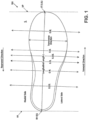
- Fig. 1 also provides information that may be useful for explaining and understanding the specification and/or aspects of this invention. More specifically, Fig. 1 provides a representation of a footwear component 100, which in this illustrated example constitutes a portion of a sole structure for an article of footwear. The same general definitions and terminology described below may apply to footwear in general and/or to other footwear components or portions thereof, such as an upper, a midsole component, an outsole component, a ground-engaging component, etc.
- the "longitudinal direction" is determined as the direction of a line extending from a rear-most heel location (RH in Fig. 1 ) to the forward-most toe location (FT in Fig. 1 ) of the footwear component 100 in question (a sole structure or foot-supporting member in this illustrated example).
- the "longitudinal length" L is the length dimension measured from the rear-most heel location RH to the forward-most toe location FT.
- the rear-most heel location RH and the forward-most toe location FT may be located by determining the rear heel and forward toe tangent points with respect to front and back parallel vertical planes VP when the component 100 (e.g., sole structure or foot-supporting member in this illustrated example, e.g., as part of an article of footwear or foot-receiving device) is oriented on a horizontal support surface S in an unloaded condition (e.g., with no weight or force applied to it other than potentially the weight/force of the shoe components with which it is engaged).
- an unloaded condition e.g., with no weight or force applied to it other than potentially the weight/force of the shoe components with which it is engaged.
- the forward-most and/or rear-most locations of a specific footwear component 100 constitute a line segment (rather than a tangent point), then the forward-most toe location and/or the rear-most heel location constitute the mid-point of the corresponding line segment. If the forward-most and/or rear-most locations of a specific footwear component 100 constitute two or more separated points or line segments, then the forward-most toe location and/or the rear-most heel location constitute the mid-point of a line segment connecting the furthest spaced and separated points and/or furthest spaced and separated end points of the line segments (irrespective of whether the midpoint itself lies on the component 100 structure). If the forward-most and/or rear-most locations constitute one or more areas, then the forward-most toe location and/or the rear-most heel location constitute the geographic center of the area or combined areas (irrespective of whether the geographic center itself lies on the component 100 structure).
- planes may be oriented perpendicular to this longitudinal direction (e.g., planes running into and out of the page of Fig. 1 ).
- the locations of these perpendicular planes may be specified based on their positions along the longitudinal length L where the perpendicular plane intersects the longitudinal direction between the rear-most heel location RH and the forward-most toe location FT.
- the rear-most heel location RH is considered as the origin for measurements (or the "0L position") and the forward-most toe location FT is considered the end of the longitudinal length of this component (or the "1.0L position").
- Plane position may be specified based on its location along the longitudinal length L (between 0L and 1.0L), measured forward from the rear-most heel RH location in this example.
- Fig. 1 shows locations of various planes perpendicular to the longitudinal direction (and oriented in the transverse direction) and located along the longitudinal length L at positions 0.25L, 0.4L, 0.5L, 0.55L, 0.6L, and 0.8L (measured in a forward direction from the rear-most heel location RH). These planes may extend into and out of the page of the paper from the view shown in Fig. 1 , and similar planes may be oriented at any other position along the longitudinal length L.
- WO 2005/089579 A3 describes a dance shoe of the half point type
- US 2012/117821 A1 describes an article of footwear with straps on its upper.
- aspects of this invention may be of particular interest for boots; athletic shoes, including basketball shoes; or other footwear, including footwear with hightop uppers.
- the claimed invention relates to an article of footwear as specified in appended independent claim 1. Specific embodiments of the claimed invention are disclosed in the dependent claims.
- an ankle strap may be engaged with the slider, and this ankle strap may include and/or may releasably engage a fastener. At least a portion of the fastener may be provided on or as part of the upper, e.g., located at the second side of the ankle-containing portion of the upper. When the closure system is in the closed condition, the fastener may engage the ankle strap with the upper to secure the upper around the wearer's ankle/foot. At least a portion of the fastener may be located between the track and a top of a foot-insertion opening of the upper, it may bridge the track, and/or it may be located below the track.
- the fastener may include any type of releasable securing component, such as one or more of: one or more snaps, one or more buttons, one or more hook-and-loop fasteners, one or more buckles, one or more laces or ties, one or more magnets, or the like.
- releasable securing component such as one or more of: one or more snaps, one or more buttons, one or more hook-and-loop fasteners, one or more buckles, one or more laces or ties, one or more magnets, or the like.
- the ankle strap when present, may extend from the first side of the ankle-containing portion (e.g., at the end of the slider track, e.g., on a lateral side of the article of footwear), across the front of the wearer's foot/ankle (e.g., across the instep-containing portion of the upper), and to the second side of the ankle-containing portion (e.g., on a medial side of the article of footwear) when the closure system is in the closed condition and the fastener for the ankle strap is engaged. At least a portion of the fastener for the ankle strap may be located at the medial side of the footwear upper.
- At least some examples of this invention may include any one or more of the following features:
- a closure system e.g., including a track and in some examples a slider engaged with the track (e.g., a zipper or other slider based closure system, as described above) may be provided that extends along a length of the foot-insertion opening, wherein movement of the slider along the track changes the closure system (and changes the foot-insertion opening) between an open condition and a closed condition.
- a slider engaged with the track e.g., a zipper or other slider based closure system, as described above
- this closure system when present, may include one or more of: one or more buttons, one or more snaps, one or more hook-and-loop fasteners, one or more buckles, one or more securing straps, one or more pressure interlocking track structures (e.g., tracks that may be opened and closed without a slider, but by hand pressure or other pressure source), one or more ties, one or more magnets, etc., provided at one or more locations along the length of the foot-insertion opening.
- this type of closure system may be omitted (e.g., and the foot-insertion opening may be held shut by an ankle strap (e.g., of the types described above and/or of the types described in more detail below) or other structure).
- the article of footwear also may include an ankle strap provided as part of or engaged with at least one of the first upper component or the second upper component (e.g., an ankle strap that extends across a central longitudinal axis of the article of footwear and/or upper and/or across the instep-containing portion of the first upper component and/or the second upper component).
- the ankle strap when present, may include and/or engage a fastener that releasably holds (partially or fully) the foot-insertion opening (and/or a closure system when present) in a closed condition.
- the first strap section may extend along a first side of a heel-containing area of the second upper component and the second strap section may extend along a second side of the heel-containing area of the second upper component.
- the first strap section may extend through the first upper component, e.g., at a first rear heel area of the first upper component, and/or the second strap section may extend through the first upper component, e.g., at the first rear heel area of the first upper component or at a second rear heel area of the first upper component.
- These strap section(s) may engage the lock at the rear heel area(s).
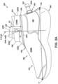
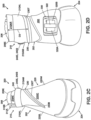
- Figs. 2A-2D provide medial, lateral, front, and rear views, respectively, of an article of footwear 200.
- This example article of footwear 200 is a hightop boot or basketball shoe. Aspects of this invention, however, also may be used in shoes for other events and/or other types of uses or activities.
- the article of footwear 200 includes an upper 202 and a sole structure 204 engaged with the upper 202.
- the upper 202 and sole structure 204 may be engaged together in any manner, including in manners conventionally known and used in the footwear arts (such as by adhesives or cements, by stitching or sewing, by mechanical connectors, etc.).
- the upper 202 also defines a foot-insertion opening 206 that allows the user's foot access to an interior foot-receiving chamber of the footwear 200.
- the foot-receiving chamber may be defined at least in part by the footwear upper 202, at least in part by the sole structure 204, and/or at least in part by other footwear components.
- the sole structure 204 may be made from any material(s) and/or number of components without departing from this invention, including conventional materials and/or conventional components/number of components as are known and used in the footwear arts.
- the sole structure 204 may include one or more midsole components (e.g., for providing one or more of impact force attenuation, comfort for the wearer, etc.) and/or one or more outsole components (e.g., for providing one or more of wear resistance, traction, a ground contacting member, etc.).
- the midsole component(s), when present, may include one or more of: one or more polymeric foam material parts (e.g., made from polyurethane foam material(s), ethylvinylacetate foam material(s), etc.); one or more fluid-filled bladders; one or more mechanical shock absorbers; etc.
- the midsole component(s), if any, may be engaged with the upper, e.g., directly with one or more upper components, such as a strobel member, an exterior upper component, an interior upper component, a bootie component, etc.
- the outsole component(s), if any, may be made from conventional outsole materials, such as natural or synthetic leather, natural or synthetic rubber, thermoplastic polyurethanes, polyurethanes, ethylvinylacetate materials, or the like.
- the outsole component(s), if any, may be engaged with one or more midsole components, one or more upper components, and/or with another footwear component.
- a single sole structure component or part may function both as an impact force attenuating component and a ground-contacting component for the article of footwear 200 (e.g., function as both a midsole component and an outsole component).
- the upper 202 of this example article of footwear 200 includes one or more upper parts that define:
- the upper 202 (and the part(s) defining the ankle-containing portion 210 and/or the part(s) defining the instep-containing portion 220) may be made from any material(s) and/or number of components without departing from this invention, including conventional materials and/or conventional components/number of components as are known and used in the footwear arts.
- This example article of footwear 200 includes a closure system 230 engaged with the upper 202, and this closure system 230 is used to change the foot-insertion opening 206 (and the closure system 230) of the upper 202 between an open condition (in which the user can insert or remove his/her foot) and a closed condition (in which the upper 202 is secured to the wearer's foot).
- the closure system 230 includes a track 230T that extends from a first end 230A (e.g., an open end) located at a first side (e.g., the lateral side) of the ankle-containing portion 210AL of the upper 202 to a second end 230B (e.g., a closed end) located at a first side (e.g., the lateral side) of the instep-containing portion 220II, of the upper 202.
- a first end 230A e.g., an open end
- a second end 230B e.g., a closed end
- the track 230T may extend: (a) around a rear ankle area 210AR of the ankle-containing portion 210 of the upper 202, (b) along a second side (e.g., the medial side) 210AM of the ankle-containing portion 210 of the upper 202, and (c) across a central portion 220IC of the instep-containing portion 220 of the upper 202 (e.g., across a central longitudinal axis of the upper 202 at a location forward of the foot-insertion opening 206).
- the central portion 220IC of the instep-containing portion 220 of the upper 202 is located between (e.g., bridges and/or connects) the first side (e.g., lateral side) 220II, of the instep-containing portion 220 of the upper 202 and the second side (e.g., medial side) 220IM of the instep-containing portion 220 of the upper 202.
- the path on the upper 202 defined by the track 230T also may define all or some of the foot-insertion opening 206 of the upper 202/article of footwear 200.
- a slider 230S is engaged with the track 230T in this example footwear 200 structure.
- the slider 230S is movable along the track 230T to change this example closure system 230 between an open condition (e.g., a foot-insertion or foot-removal condition) and a closed condition (e.g., a foot-securing condition).
- the track 230T and slider 230S may constitute a zipper type closure system or other slider based type closure system (e.g., an interlocking track structure with slider or the like).
- the slider 230S could be omitted and the track 230T may constitute an interlocking track that can be closed by applying pressure to the interlocking track parts and opened by a separation/pulling force (e.g., akin to a closure track along re-sealable food storage bags).
- a separation/pulling force e.g., akin to a closure track along re-sealable food storage bags.
- this closure system 230 may include one or more of: one or more buttons, one or more snaps, one or more hook-and-loop fasteners, one or more buckles, one or more securing straps (e.g., including an ankle strap), one or more ties, one or more magnets, etc., provided at one or more locations along the length of the foot-insertion opening 206 and/or the length of the closure system 230 track 230T (e.g., from first end 230A to second end 230B along track 230T).
- this example article of footwear 200 includes an ankle strap 240, e.g., that extends around the front ankle covering portion 210AF and/or across a central instep-containing portion 220IC of the upper 202 to help secure the article of footwear 200 to a wearer's foot.
- the ankle strap 240 may be engaged with the slider 230S of the closure system 230.
- the ankle strap 240 of this example includes and/or engages with a fastener to releasably secure to the upper 202.
- the fastener may include an engagement element 240E that releasably engages a securing component 240S engaged with the upper 202, e.g., at the second side of the ankle-containing portion (e.g., the medial side 210AM).
- the ankle strap 240 releasably engages with the securing component 240S to change the ankle strap 240, the foot-insertion opening 206, and/or the overall closure system 230 between an open condition (in which the ankle strap 240 is disengaged from the securing component 240S, described in more detail in conjunction with Figs 3A-3E ) and a closed condition (in which the ankle strap 240 is engaged with the securing component 240S, e.g., as shown in Figs. 2A-2D ).
- any type of fastener may be used without departing from this invention, including one or more of: a combination of an engagement element 240E included with the ankle strap 240 and a securing component 240S engaged with the upper 202; one or more snaps; one or more buttons; one or more hook-and-loop fasteners; one or more buckles; one or more laces or ties; one or more magnets; or the like.
- the fastener includes the combination of securing element 240E and its cooperating securing component 240S, which are structurally parts of a conventional releasable snap connector.
- the ankle strap 240 extends from the first side 210AL of the ankle-containing portion 210 (e.g., the lateral side) of the upper 202 to the second side 210AM of the ankle-containing portion 210 (e.g., the medial side) when the foot-insertion opening 206, the closure system 230, and/or the strap 240 is/are in the closed condition. Additional details of this ankle strap 230, its engagement with the upper 202, and its transition between the open condition and the closed condition will be described in more detail in conjunction with Figs. 3A-3E .
- Figs. 2A-2D illustrate additional example features of articles of footwear 200 and components thereof in accordance with at least some examples of this invention.
- a portion of the track 230 at the second side 210AM of the ankle-containing portion 210 may be located a distance D1 of less than 1.5 inch (3.81 cm), and in some examples, less than 1.25 inch (3.18 cm), less than 1 inch (2.54 cm), or even less than 0.75 inch (1.91 cm), from at least a portion of the engagement element 240E (when the ankle strap 240 is secured) or its cooperating securing component 240S.
- Figs. 2A-2D illustrate additional example features of articles of footwear 200 and components thereof in accordance with at least some examples of this invention.
- a portion of the track 230 at the second side 210AM of the ankle-containing portion 210 may be located a distance D1 of less than 1.5 inch (3.81 cm), and in some examples, less than 1.25 inch (3.18 cm), less than 1 inch (2.54 cm), or even less than 0.75 inch
- the engagement element 240E and/or its corresponding securing component 240S may be located between the track 230T and a top (e.g., top edge 206E) of the foot-insertion opening 206 of the upper 202.
- a portion of the track 230T at the second side 210AM of the ankle-containing portion 210 may be located a distance D2 of less than 2.25 inches (5.72 cm), less than 2 inches (5.08 cm), less than 1.75 inch (4.45 cm), less than 1.5 inch (3.81 cm), or even less than 1.25 inch (3.18 cm) from a top (e.g., a top edge 206E) of the foot-insertion opening 206 of the upper 202.
- a top of the rearmost ankle portion of the track 230T may be located a distance D3 of less than 2 inches (5.08 cm), and in some examples, less than 1.75 inch (4.45 cm), less than 1.5 inch (3.81 cm), or even less than 1.25 inch (3.18 cm), from a rearmost top point or top edge 206E of the upper 202.
- the distance D3 may be measured from a top of the track 230T at the rearmost heel location RH of the upper 202 to a rearmost top point or a rearmost top edge 206E of the foot-insertion opening 206 of the upper 202 at the rearmost heel location RH of the upper 202.
- the first end 230A of the track 230 may be located a distance D4 of less than 2 inches (5.08 cm), and in some examples, less than 1.75 inch (4.45 cm), less than 1.5 inch (3.81 cm), or even less than 1.25 inch (3.18 cm), from a top (e.g., the top edge 206E) of the foot-insertion opening 206 of the upper 202, e.g., when the upper 202 and foot-insertion opening 206 are in a closed condition and the footwear 200 is supported on a horizontal base surface in an unloaded condition.
- the second end 230B of track 230T in at least some examples of this invention is located on the first side 220IL of the instep-containing portion 220 of the upper 202 (e.g., the same side of the upper 202 at which the first end 230A of the track 230T and/or foot-insertion opening 206 is/are located). Additionally or alternatively, as shown in Fig.
- Figs. 2A-2D further illustrate that the upper 202 of this example article of footwear 200 includes a heel support 250 that extends at least around the heel area of the upper 202.
- the heel support 250 may function, at least in part, as a conventional heel counter type structure or other heel support structure for the article of footwear 200.
- the heel support 250 of the upper 202 includes a lock 330, which will be described in more detail below, e.g., in conjunction with Figs. 3A through 4G .
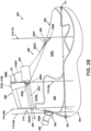
- FIG. 3A-3E further show one manner in which such articles of footwear and uppers, including the article of footwear 200, the upper 202, the closure system 230, and the strap 240 of Figs. 2A-2D , can be changed between the open condition (e.g., a foot-insertion or foot-removal configuration) and the closed condition (e.g., a foot-securing configuration).
- open condition e.g., a foot-insertion or foot-removal configuration
- the closed condition e.g., a foot-securing configuration
- this example article of footwear 300 includes a first upper component 302A (e.g., an exterior upper component) and a second upper component 302B (e.g., an interior upper component). These upper components 302A and 302B may be fixed together or may be separable from one another.
- a foot-insertion opening 206 is at least in part defined by the first upper component 302A.
- the foot-insertion opening 206 extends: (a) from a first side 210AL of an ankle-containing portion 210 of the first upper component 302A, (b) around a rear heel or ankle area 210AR of the first upper component 302A, (c) along a second side 210AM of the ankle-containing portion 210 of the first upper component 302A, (d) across an instep-containing portion 220 of the first upper component 302A, and (e) to a first side 220IL of the instep-containing portion 220 of the first upper component 302A.
- One or more of the above-noted portions of the foot-insertion opening 206 described in items (a) through (e) above also may include a closure system 230, such as a track 230T and slider 230S or other types of closure systems, as described in more detail above.
- the top edge 206E of the first upper component 302A also forms a portion of the foot-insertion opening 206 of this example.
- This top edge 206E may include elastic or other material, e.g., to form fit and/or securely engage with a wearer's ankle/leg.
- a sole structure 204 may be engaged with at least one of the first upper component 302A and/or the second upper component 302B (or another footwear component part).
- the article of footwear 300 shown in Figs. 3A-3E further may include an ankle strap 240 and/or a fastener (e.g., 240E/240S) for the ankle strap 240, e.g., having any of the features and/or alternatives for these components as described above for Figs. 2A-2D .
- a fastener e.g., 240E/240S
- the foot-insertion opening 206 and/or the closure system 230 may be interchangeable between: (a) a closed condition (e.g., a foot-securing condition as shown in Figs. 2A-2D ) in which the footwear 200, 300 may be secured to a wearer's foot and (b) an open condition (e.g., a foot-insertion or foot-removal condition as most completely shown in Fig. 3C ) in which the foot may be inserted or removed from the upper 202/302A.
- a closed condition e.g., a foot-securing condition as shown in Figs. 2A-2D
- an open condition e.g., a foot-insertion or foot-removal condition as most completely shown in Fig. 3C
- the ankle-containing portion 210 of the upper 202/302A may constitute a "flap" of material or other flexible component that wraps around and releasably secures around the wearer's foot/ankle (e.g., using the closure system 230 and/or ankle strap 240).
- the ankle-containing portion 210 of these example uppers 202/302A includes a first end 310A that meets (and may overlap with) a second end 310B when the ankle-containing portion 210 of the upper 202/302A is in the closed condition.
- These ends 310A/310B may define an ankle-wrapping portion of this example upper 202/302A.
- the first ankle-wrapping end 310A overlaps with the second ankle-wrapping end 310B when the ankle-containing portion 210 of the upper 202/302A is in the closed condition.
- a fastener could be provided at one or both of first ankle-wrapping end 310A and/or second ankle-wrapping end 310B to secure these ends 310A/310B together.
- Such fasteners may include one or more of: one or more snaps, one or more buttons, one or more hook-and-loop fasteners, one or more buckles, one or more laces or ties, one or more magnetic connectors/fasteners, or the like. In the illustrated example, however, no fasteners are included at these two ends 310A/310B, but the ends 310A/3 10B simply overlap when in the closed configuration. As shown in Fig.
- the second ankle-wrapping end 310B of the ankle-containing portion 210 vertically aligns with or vertically overlaps with the first end 230A of the track 230T (and/or the end of the foot-insertion opening 206 vertically aligns with or vertically overlaps with the second ankle-wrapping end 310B).
- the top of the ankle-covering portion 210 of the upper component 302A will completely surround the wearer's ankle/leg when the foot-insertion opening 206 and/or closure system 230 (when present) is fully closed (e.g., when the slider 230S is at the end 230A of the track 230T).
- the two ends 310A/310B may abut one another or lie within close proximity to one another (the term "close proximity" as used herein in this specific context means at least some portion of first ankle-wrapping end 310A is located within 1 inch (2.54 cm) of at least some portion of second ankle-wrapping end 310B).
- the degree of overlap or separation of the ends 310A/310B may depend, at least in part, on the circumference of the wearer's leg, the degree of stretch on elastic in the top edge 206E (if any), and/or a user's desired degree of tightness for the top edge 206E of the foot-insertion opening 206 around his/her leg.
- the second upper component 302B (e.g., an "interior" upper component) of the upper of this example article of footwear 300 now will be described in more detail.
- the second upper component 302B constitutes a bootie that at least partially defines an interior chamber 308 for receiving a wearer's foot.
- the second upper component 302B may completely or partially define the interior chamber 308, and it may be fully or partially contained within/received in the first upper component 302A (which may constitute an exterior upper component). Access to the interior chamber 308 is provided by a foot-insertion opening 306 defined by the second upper component 302B.
- the second upper component 302B may be completely concealed when the first upper component 302A, the foot-insertion opening 206, and/or the closure system 230 is/are in the closed condition. If desired, however, some portion of second upper component 302B could be visible and/or exposed when the first upper component 302A, the foot-insertion opening 206, and/or the closure system 230 is/are in the closed condition.
- This illustrated example footwear 300 structure includes additional structure to tighten and secure the second upper component 302B to a wearer's foot.
- the article of footwear 300 includes a first strap section 320A extending between the first upper component 302A and the second upper component 302B and across and beneath a central instep-containing portion 220IC of the first upper component 302A.
- This example strap section 320A extends from the lateral forefoot and/or lateral instep-containing portion 220IL of the overall upper to the medial ankle-containing portion 210AM of the overall upper.
- the article of footwear 300 further includes a second strap section 320B extending between the first upper component 302A and the second upper component 302B and across and beneath the central instep-containing portion 220IC of the first upper component 302A.
- This example strap section 320B extends from the medial forefoot and/or medial instep-containing portion 220IM of the overall upper to the lateral ankle-containing portion 210AL of the overall upper.
- the first strap section 320A crosses the second strap section 320B at a location forward of the foot-receiving opening 306 of the interior upper component 302B (e.g., a foot-receiving bootie).
- strap sections 320A/320B may be permanently or releasably engaged with the footwear 300 upper and/or sole structure 204 at the medial and/or lateral forefoot area(s) and/or at the medial and/or lateral midfoot area(s) of the article of footwear 300 (e.g., by one or more of stitching, adhesive, mechanical connector(s), etc.).
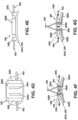
- the first strap section 320A extends along the medial ankle-containing portion 210AM inside the first upper component 302A and outside the second upper component 302B and exits from this intermediate location to an area outside the first upper component 302A at a rear heel area of the first upper component 302A (e.g., through an opening 304M provided at the rear heel area, e.g., an opening 304M through heel support 250 as shown in Figs. 4D, 4F, and 4G ).
- the second strap section 320B extends along the lateral ankle-containing portion 210AL inside the first upper component 302A and outside the second upper component 302B and exits from this intermediate location to an area outside the first upper component 302A at a rear heel area of the first upper component 302A (e.g., through an opening 304L provided at the rear heel area, e.g., an opening 304L through heel support 250 as shown in Figs. 4D, 4F, and 4G ).
- the second strap section 320B may extend outside of first upper component 302A from its intermediate location between the first upper component 302A and the second upper component 302B through the same opening in upper component 302A and/or heel support 250 as the first strap section 320A or through a separate and independent opening (e.g., openings 304M and 304L in Figs. 4D, 4F, and 4G and described above may be a single opening through which both strap sections 320A-320B extend).
- a separate and independent opening e.g., openings 304M and 304L in Figs. 4D, 4F, and 4G and described above may be a single opening through which both strap sections 320A-320B extend.
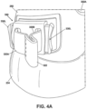
- the rear heel area of the first upper component 302A in this illustrated example includes a lock 330 for engaging one or both strap sections 320A/320B.
- the lock 330 may be engaged with at least one of the first upper component 302A, the second upper component 302B, the first strap section 320A, the second strap section 320B, and/or the sole structure 204 of the article of footwear.
- This lock 330 releasably holds at least one of the first strap section 320A and the second strap section 320B around the wearer's foot, e.g., in a tightened condition.
- the lock 330 engages both the first strap section 320A and the second strap section 320B.
- the strap sections 320A/320B of this example are joined together at their free ends by pull tab 322.
- the pull tab 322 can be formed of a separate part to which the free ends of strap sections 320A/320B are engaged (e.g., by sewing, adhesives, mechanical connectors, etc.) and/or the pull tab 322 can be formed by securing the free ends of strap sections 320A/320B together without a separate part (e.g., by sewing, adhesives, mechanical connectors, etc. engaging the strap section free ends together).
- the first strap section 320A and the second strap section 320B can be tightened around the wearer's foot by pulling pull tab 322 outward.
- This action is shown by arrow 324 in Fig. 4B , and it shortens the length of both the first strap section 320A and the second strap section 320B in the interior of the upper (e.g., in the volume between the first upper component 302A and the second upper component 302B) thereby tightening the strap sections 320A/320B around a wearer's foot.
- This action also is shown in sequence by the arrangement shown in Fig. 4B changing to the arrangement shown in Fig. 4C .
- the lock 330 can be activated (examples of which will be described in more detail below) to hold the strap section(s) 320A/320B at a fixed location with respect to the lock 330 (e.g., as shown in Fig. 4C ).
- the strap sections 320A/320B can be tightened before or after the first upper component 302A is secured around the wearer's foot.
- the first upper component 302A may be secured around the wearer's foot, for example: (a) by sliding slider 230S along track 230T from the second end 230B to the first end 230A or otherwise closing the closure system 230 and/or (b) by securing the ankle strap 240 around the wearer's ankle/leg by engaging fastener element 240E with cooperating fastener element 240S or otherwise securing a fastener.
- the first strap section 320A and the second strap section 320B engage an additional component, e.g., an additional strap section 320C, and this additional component is used to loosen the first strap section 320A and/or the second strap section 320B from its/their tightened condition around the wearer's foot. More specifically, in this example, the loosening component (e.g., strap section 320C) forms a loop, and the first strap section 320A and the second strap section 320B pass through this loop.
- an additional component e.g., an additional strap section 320C
- the loosening component (e.g., strap section 320C) loop is located at a central instep-covering portion of the overall upper (e.g., between the first upper component 302A and the second upper component 302B) and/or forward of the foot-insertion opening 306 of the second upper component 302B, e.g., as shown in Fig. 3E .
- the loosening component need not constitute a strap portion.
- it may constitute a pull tab, a ring, a hardware element, or any other type of structure that will allow a user to pull one or more of the strap portions 320A and/or 320B upward from the wearer's foot and/or forward and away from the wearer's leg/ankle to loosen them from the tightened condition.
- the footwear 300 removal process now will be described in more detail with reference to Figs. 3A-3E , e.g., starting with a secured shoe as shown in Figs. 2A-2D .
- the ankle strap 240 is loosened, e.g., by disengaging the ankle strap fastener (e.g., by disengaging ankle strap fastener element 240E from the upper based fastener component 240S).
- the foot-insertion opening 206 of the first upper component 302A is opened by unwrapping the ankle-containing flap 210 of the first upper component 302A from around the wearer's leg.
- this action may require moving slider 230S along track 230T from the first end 230A to the second end 230B (or otherwise disengaging any present type of closure system for foot-receiving opening 206).
- the lock 330 then may be unlocked, and the wearer then may pull the loosening component (e.g., strap section 320C) forward, e.g., as shown by arrow 326 in Figs. 3C-3E .
- the loosening component e.g., strap section 320C
- first strap section 320A and the second strap section 320B are adequately loosened, the wearer's foot can be removed from the interior chamber 308 through foot-insertion opening 306 and foot-insertion opening 206.
- a separate loosening component e.g., strap section 320C
- strap section 320C can be omitted and the strap section(s) 320A and/or 320B can be loosened by pulling them back into the upper.
- the above noted steps also may take place in a different order and/or some steps may occur simultaneously.
- the lock 330 includes a base 330B with one or more openings defined through it and through which the strap sections 320A and 320B extend (e.g., aligned with or included as part of the openings 304L and 304M in the upper component 302A/heel support 250).
- a spring-loaded lock 330L may be engaged with the base 330B in a manner so that the spring-loaded lock 330L can slide inward and outward with respect to the base 330B. As shown in Fig.
- the opening(s) 304L and/or 304M are "closed off” to pinch the strap sections 320A/320B between the bearing surfaces 404 of the lock 330L and the base 330 and prevent relative movement of: (a) the strap section(s) 320A/320B with respect to (b) the lock base 330B, the upper component 302A, the upper component 302B, and/or the heel support 250.
- Spring 330S biases the lock 330L into the "relaxed" or locked configuration of Fig. 4F , in this illustrated example lock 330 structure.
- This "compressed" lock 330 condition opens up at least one of the openings 304L/304M and allows the strap section(s) 320A/320B to move with respect to at least some portion of the lock 330 (e.g., the lock base 330B).
- This compressed lock 330 condition also allows the strap section(s) 320A/320B to be tightened or loosened, as desired by a user.
- at least some portion of the opening(s) 304L and/or 304M are "opened up” to allow easy and relative movement of the strap section(s) 320A/320B with respect to the lock base 330B, the upper component 302A, the upper component 302B, and/or the heel support 250.
- the two strap sections 320A and 320B may constitute portions of a single continuous strap. Additionally or alternatively, only one of the strap sections 320A or 320B might engage a lock (whether the strap sections 320A/320B constitute part of one strap or two separate strap), and the other strap section could be fixed with respect to the footwear upper (e.g., to allow only one strap section to be tightened or loosened, to allow tightening or loosening of one strap section with the lock to tighten or loosen both strap sections (when the two strap sections are part of a single, continuous strap), etc.).
- each strap section 320A, 320B may be provided for each strap section 320A, 320B.
- one or more locks may be provided at other locations on the footwear 300 structure, such as at one or more of: at a lateral heel and/or lateral ankle side of the upper and/or sole structure, at the medial heel and/or medial ankle side of the upper and/or sole structure, at a top instep-containing area 220IC of the upper, etc.
- Other types of locks may include, for example, one or more of: a ratcheted take-up reel that engages one or more of the strap sections 320A/320B (e.g., in a rotary manner); one or more clamps (e.g., that prevents the strap section(s) from moving inward through opening(s) 304L/304M); one or more clips (e.g., that prevents the strap section(s) from moving inward through opening(s) 304L/304M); one or more buckles; one or more buttons; one or more snaps; one or more retaining elements; etc.
- a ratcheted take-up reel that engages one or more of the strap sections 320A/320B (e.g., in a rotary manner); one or more clamps (e.g., that prevents the strap section(s) from moving inward through opening(s) 304L/304M); one or more clips (e.g., that prevents the strap section(s) from moving inward through opening(
- foot-insertion opening 206 and the track 230T are described above and shown in Figs. 2A-3E as extending across the central instep-containing portion 220IC of the upper 202 from the second side of the instep-containing portion (e.g., 220IM) to the first side of the instep containing portion (e.g., 220IL) (e.g., across a central longitudinal axis of the upper at a forefoot portion of the upper), these features are not required in all embodiments of the present invention. Rather, in some embodiments of the invention, as illustrated by arrows 230B (ALT) in Fig.
- the foot-insertion opening 206 of the upper 202 and/or the track 230T may extend: (i) from a first side of an ankle-containing portion (e.g., 210AL) of the upper 202, (ii) around a rear heel or ankle area (e.g., 210AR) of the upper 202, (iii) along a second side of the ankle-containing portion (e.g., 210AM) of the upper 202, and (iv) to an instep-containing portion of the upper 202.
- an ankle-containing portion e.g., 210AL
- a rear heel or ankle area e.g., 210AR
- a second side of the ankle-containing portion e.g., 210AM
- the end of the foot-insertion opening 206 and/or the closed end 230B of the track 230T may be located at the forefoot portion of the upper at or at a location short of a central longitudinal axis (Long. Axis, Fig. 3C ) of the upper 202 at the forefoot portion of the upper 202 (e.g., and not across the central longitudinal axis (Long. Axis) of the upper 202 at the forefoot portion of the upper 202).
- a central longitudinal axis Long. Axis, Fig. 3C
- Figs. 5A and 5B illustrate another example and/or additional details of an article of footwear 500, a first upper component 502 (which may constitute an interior upper component fit into or at least partially contained in an exterior upper component), and/or strap portions 520A/520B in accordance with at least some examples of this invention.
- a first upper component 502 which may constitute an interior upper component fit into or at least partially contained in an exterior upper component
- strap portions 520A/520B in accordance with at least some examples of this invention.
- the strap portions 520A and 520B, the first upper component 502, and/or the relative arrangement of these parts as described in more detail below in conjunction with Figs. 5A and 5B also could be used in the various embodiments of the invention described above in conjunction with Figs. 2A through 4G .
- This example footwear 500 structure includes at least a first upper component 502, a second upper component 550, and a sole structure 504 engaged with at least one of the first upper component 502 and/or the second upper component 550.
- the first upper component 502 is at least partially contained in the second upper component 550 in this example footwear structure 500.
- the first upper component 502 is fully contained in the second upper component 550.
- the strap portions 520A and 520B are provided as separate straps that are engaged at their free ends, e.g., by pull tab 322, e.g., in any manner as described above for strap sections 320A/320B.
- First strap section 520A extends from a medial midfoot and/or medial forefoot area of the article of footwear 500, across the instep area of the article of footwear 500, inside second upper component 550 and between second upper component 550 and first upper component 502, through an opening at the lateral heel side area of the second upper component 550 (to the outside of second upper component 550), along the outside of the lateral heel side area of the second upper component 550, to the lock 330 and pull tab 322.
- the first strap portion 520A can be fixed to the first upper component 502 and/or the sole structure 504 (and/or another footwear component) at the medial midfoot and/or medial forefoot area (e.g., by stitching, adhesive, mechanical connector(s), etc.), e.g., at a location where the first upper component 502, sole structure 504, and first strap portion 520A meet.
- second strap section 520B extends from a lateral midfoot and/or lateral forefoot area of the article of footwear 500), across the instep area of the article of footwear 500, inside second upper component 550 and between second upper component 550 and first upper component 502, through an opening 504M at the medial heel side area of the second upper component 550 (to the outside of second upper component 550), along the outside of the medial heel side area of the second upper component 550, to the lock 330 and pull tab 322.
- the second strap portion 520B can be fixed to the first upper component 502 and/or the sole structure 504 (and/or another footwear component) at the lateral midfoot and/or lateral forefoot area (e.g., by stitching, adhesive, mechanical connector(s), etc.), e.g., at a location where the first upper component 502, sole structure 504, and second strap portion 520B meet.
- the lateral side of the second upper component 550 may have an opening like opening 504M shown on the medial side in Fig. 5A , and the first strap portion 520A may extend through this lateral side opening to the outside of the second upper component 550, as described above.
- the two strap portions 520A/520B cross one another at an instep area of the article of footwear 500, e.g., in front of and/or above any foot-receiving opening 5020 of upper component 502.
- First upper component 502 and/or second upper component 550 may be located at least partially inside another upper component (not shown in Fig. 5A , but potentially like upper component 302A), and the lock 330 may be engaged with that additional upper component. Additionally or alternatively, the lock 330 may be engaged with the second upper component 550 and/or the first upper component 502.
- the second upper component 550 may constitute a heel support component (e.g., like heel support 250 and/or a heel counter) and/or may be an exterior component of the article of footwear 500 (e.g., like a heel counter).
- the first upper component 502 may have another upper component at least partially (or even fully) contained within it.
- Fig. 5B illustrates some additional details of the strap sections 520A, 520B that may be provided in at least some examples of this invention.
- the strap sections 520A, 520B of this example include a wider forefoot and/or instep section 522 (e.g., having width W1), a tapered section 524, and a narrower midfoot and/or heel/ankle section 526 (e.g., having a width W2).
- the tapered section 524 may taper in width from W1 to W2.
- the wider forefoot and/or instep section 522 has a longitudinal length L1, the tapered section 524 has a longitudinal length L2, and the narrower midfoot and/or heel/ankle section 526 has a longitudinal length L3.
- the wider forefoot and/or instep section 522 (e.g., having width W1) of strap portions 520A and/or 520B (as compared to the midfoot and/or heel/ankle section 526) may provide a wider area over which force is applied to a wearer's foot when the strap portion(s) 520A, 520B are tightened, thereby improving the comfort of the strap portion 520A/520B on the wearer's foot and directly engaging a larger portion of the wearer's foot.
- the narrower midfoot and/or heel/ankle section 526 can reduce the size of the lock 330 and the hardware associated with it, thereby reducing its weight and/or bulkiness and making the strap portions 520A/520B easier to handle.
- the strap portions 520A and 520B may have the same or different L1, L2, L3, W1, and/or W2 dimensional characteristics in a single footwear 500 structure.
- either or both of strap sections 520A and/or 520B may have a constant width over their entire longitudinal lengths; either or both of strap sections 520A and/or 520B may have a continuously tapering width over their entire longitudinal lengths; and/or either or both of strap sections 520A and/or 520B may have one or more stepped width changes or otherwise varied width changes over their longitudinal lengths.
Landscapes
- Footwear And Its Accessory, Manufacturing Method And Apparatuses (AREA)
- Health & Medical Sciences (AREA)
- General Health & Medical Sciences (AREA)
- Physical Education & Sports Medicine (AREA)
Claims (13)
- Schuhwerk (200, 300, 500), umfassend:eine erste Schaftkomponente (302A);eine zweite Schaftkomponente (302B);einen ersten Bandabschnitt (320A, 520A), der sich zwischen der ersten Schaftkomponente (302A) und der zweiten Schaftkomponente (302B) und über einen den Spann enthaltenden Abschnitt (220) der ersten Schaftkomponente (302A) und unter diesem erstreckt;einen zweiten Bandabschnitt (320B, 520B), der sich zwischen der ersten Schaftkomponente (302A) und der zweiten Schaftkomponente (302B) und über den den Spann enthaltenden Abschnitt (220) der ersten Schaftkomponente (302A) und unter diesem erstreckt;eine Sohlenstruktur (204, 504), die mit mindestens einer von der ersten Schaftkomponente (302A) oder der zweiten Schaftkomponente (302B) in Eingriff steht; undeine Verriegelung (330), die mit mindestens einem von der ersten Schaftkomponente (302A), der zweiten Schaftkomponente (302B), dem ersten Bandabschnitt (320A, 520A), dem zweiten Bandabschnitt (320B, 520B) oder der Sohlenstruktur (204, 504) in Eingriff steht;und wobei: (a) sich der erste Bandabschnitt (320A, 520A) von einem medialen Mittelfuß- und/oder medialen Vorfußbereich des Schuhwerks (200, 300, 500) über den den Spann enthaltenden Abschnitt (220) eines Schafts (202) des Schuhwerks (200, 300, 500) und unter diesem, um einen seitlichen Knöchelbereich (210AL) des Schafts (202) herum und zu einem hinteren Fersenbereich (210AR) des Schafts (202) erstreckt, wobei die Verriegelung (330) den ersten Bandabschnitt (320A, 520A) in einem gestrafften Zustand lösbar hält; und/oder (b) sich der zweite Bandabschnitt (320B, 520B) von einem seitlichen Mittelfuß- und/oder seitlichen Vorfußbereich des Schuhwerks (200, 300, 500) über den den Spann enthaltenden Abschnitt (220) des Schafts (202) und unter diesem, um den medialen Knöchelbereich (210AM) des Schafts (202) herum und zu dem hinteren Fersenbereich des Schafts (202) erstreckt, wobei die Verriegelung (330) den zweiten Bandabschnitt (320B, 520B) in einem gestrafften Zustand lösbar hält.
- Schuhwerk (200, 300, 500) nach Anspruch 1, ferner umfassend eine Fußeinführöffnung (306, 5020), die zumindest zum Teil durch die erste Schaftkomponente (302A) definiert ist, wobei sich die Fußeinführöffnung (306, 5020) erstreckt: (a) von einer ersten Seite eines den Knöchel enthaltenden Abschnitts (210AL) der ersten Schaftkomponente (302A), (b) um einen hinteren Fersen- oder Knöchelbereich (210AR) der ersten Schaftkomponente (302A), (c) entlang einer zweiten Seite des den Knöchel enthaltenden Abschnitts (210AM) der ersten Schaftkomponente (302A) und (d) zu einem den Spann enthaltenden Abschnitt (220) der ersten Schaftkomponente (302A).
- Schuhwerk (200, 300, 500) nach Anspruch 2, wobei: (i) sich die Fußeinführöffnung (306, 5020) über den den Spann enthaltenden Abschnitt (220) der ersten Schaftkomponente (302A) und zu einer ersten Seite des den Spann enthaltenden Abschnitts (220IL) der ersten Schaftkomponente (302A) und über eine Mittellängsachse eines Schafts (202) des Schuhwerks (200, 300, 500) an einem Vorfußabschnitt der ersten Schaftkomponente (302A) erstreckt; oder (ii) sich die Fußeinführöffnung (306, 5020) zu einer Stelle in einem Vorfußabschnitt der ersten Schaftkomponente (302A) an oder kurz vor einer Mittellängsachse der ersten Schaftkomponente (302A) an dem Vorfußabschnitt der ersten Schaftkomponente (302A) und nicht über die Mittellängsachse der ersten Schaftkomponente (302A) an dem Vorfußabschnitt der ersten Schaftkomponente (302A) erstreckt.
- Schuhwerk (200, 300, 500) nach Anspruch 2 oder 3, ferner umfassend: eine Schiene (230T), die mit der ersten Schaftkomponente (302A) in Eingriff steht, und einen Schieber (230S), der mit der Schiene (230T) in Eingriff steht, wobei eine Bewegung des Schiebers (230S) entlang der Schiene (230T) die Fußeinführöffnung (306, 5020) zwischen einem offenen Zustand und einem geschlossenen Zustand verändert.
- Schuhwerk (200, 300, 500) nach Anspruch 4, ferner umfassend:ein Knöchelband (240), das mit dem Schieber (230S) in Eingriff steht; undeinen Verschluss (240E, 240S), der das Knöchelband (240) mit mindestens einer von der ersten Schaftkomponente (302A) oder der zweiten Schaftkomponente (302B) lösbar sichert, wenn sich die Fußeinführöffnung (306, 5020) in dem geschlossenen Zustand befindet.
- Schuhwerk (200, 300, 500) nach Anspruch 1, ferner umfassend:ein Knöchelband (240), das mit mindestens einer von der ersten Schaftkomponente (302A) oder der zweiten Schaftkomponente (302B) in Eingriff steht; undeinen Verschluss (240E, 240S), der das Knöchelband (240) mit mindestens einer von der ersten Schaftkomponente (302A) oder der zweiten Schaftkomponente (302B) lösbar sichert, wenn sich eine Fußeinführöffnung (306, 5020), die zumindest zum Teil durch die erste Schaftkomponente (302A) definiert ist, in einem geschlossenen Zustand befindet.
- Schuhwerk (200, 300, 500) nach einem der Ansprüche 1 bis 6, wobei die erste Schaftkomponente (302A) eine äußere Schaftkomponente (302A, 250, 550) beinhaltet und wobei die zweite Schaftkomponente (302B) zumindest teilweise in der äußeren Schaftkomponente (302A, 250, 550) aufgenommen ist.
- Schuhwerk (200, 300, 500) nach Anspruch 7, wobei die zweite Schaftkomponente (302B) einen den Fuß aufnehmenden Innenschuh beinhaltet.
- Schuhwerk (200, 300, 500) nach Anspruch 7 oder Anspruch 8, wobei sich der erste Bandabschnitt (320A, 520A) entlang einer ersten Seite eines die Ferse enthaltenden Bereichs der zweiten Schaftkomponente (302B) erstreckt und sich der zweite Bandabschnitt (320B, 520B) entlang einer zweiten Seite des die Ferse enthaltenden Bereichs der zweiten Schaftkomponente (302B) erstreckt.
- Schuhwerk (200, 300, 500) nach Anspruch 9, wobei sich der erste Bandabschnitt (320A, 520A) durch die erste Schaftkomponente (302A) an einem ersten hinteren Fersenbereich der ersten Schaftkomponente (302A) erstreckt und wobei sich der zweite Bandabschnitt (320B, 520B) durch die erste Schaftkomponente (302A) an dem ersten hinteren Fersenbereich der ersten Schaftkomponente oder an einem zweiten hinteren Fersenbereich der ersten Schaftkomponente (302A) erstreckt.
- Schuhwerk (200, 300, 500) nach einem der Ansprüche 1 bis 10, wobei die Verriegelung (330) mit mindestens einem von dem ersten Bandabschnitt (320A, 520A) oder dem zweiten Bandabschnitt (320B, 520B) in Eingriff gelangt und wobei sich die Verriegelung (330) an einem hinteren Fersenbereich mindestens einer von der ersten Schaftkomponente (302A) oder der zweiten Schaftkomponente (302B) befindet.
- Schuhwerk (200, 300, 500) nach einem der Ansprüche 1 bis 6, wobei die erste Schaftkomponente (302A) eine äußere Schaftkomponente (302A, 250, 550) beinhaltet und wobei sich zumindest ein Abschnitt der Verriegelung (330) an einem hinteren Fersenbereich der äußeren Schaftkomponente (302A, 250, 550) befindet.
- Schuhwerk (200, 300, 500) nach einem der vorhergehenden Ansprüche, wobei die Verriegelung (330) eine Verriegelungsbasis (330B) mit einer oder mehreren durch sie hindurch definierten Öffnungen und eine federbelastete Verriegelung (330L) beinhaltet, die mit der Verriegelungsbasis (330B) derart in Eingriff steht, dass sich die federbelastete Verriegelung (330L) in Bezug auf die Verriegelungsbasis (330B) nach innen und nach außen verschieben kann, und wobei sich der erste Bandabschnitt (320A, 520A) und der zweite Bandabschnitt (320B, 520B) durch die eine oder mehreren Öffnungen erstrecken, die durch die Verriegelungsbasis (330B) hindurch definiert sind.
Applications Claiming Priority (4)
| Application Number | Priority Date | Filing Date | Title |
|---|---|---|---|
| US201762582988P | 2017-11-08 | 2017-11-08 | |
| EP18807828.1A EP3706591B1 (de) | 2017-11-08 | 2018-11-08 | Schuhwerk mit wickelverschlusssystem und/oder fuss-wickelsicherungsbändern |
| PCT/US2018/059788 WO2019094565A1 (en) | 2017-11-08 | 2018-11-08 | Articles of footwear with wrap around closure system and/or foot wrapping securing straps |
| EP21196885.4A EP3949789B1 (de) | 2017-11-08 | 2018-11-08 | Schuhwerk mit wickelverschlusssystem und/oder fusswickelsicherungsbändern |
Related Parent Applications (3)
| Application Number | Title | Priority Date | Filing Date |
|---|---|---|---|
| EP21196885.4A Division EP3949789B1 (de) | 2017-11-08 | 2018-11-08 | Schuhwerk mit wickelverschlusssystem und/oder fusswickelsicherungsbändern |
| EP21196885.4A Division-Into EP3949789B1 (de) | 2017-11-08 | 2018-11-08 | Schuhwerk mit wickelverschlusssystem und/oder fusswickelsicherungsbändern |
| EP18807828.1A Division EP3706591B1 (de) | 2017-11-08 | 2018-11-08 | Schuhwerk mit wickelverschlusssystem und/oder fuss-wickelsicherungsbändern |
Publications (2)
| Publication Number | Publication Date |
|---|---|
| EP4098141A1 EP4098141A1 (de) | 2022-12-07 |
| EP4098141B1 true EP4098141B1 (de) | 2024-02-14 |
Family
ID=64453640
Family Applications (3)
| Application Number | Title | Priority Date | Filing Date |
|---|---|---|---|
| EP22187048.8A Active EP4098141B1 (de) | 2017-11-08 | 2018-11-08 | Schuhwerk mit wickelverschlusssystem und/oder fusswickelsicherungsbändern |
| EP18807828.1A Active EP3706591B1 (de) | 2017-11-08 | 2018-11-08 | Schuhwerk mit wickelverschlusssystem und/oder fuss-wickelsicherungsbändern |
| EP21196885.4A Active EP3949789B1 (de) | 2017-11-08 | 2018-11-08 | Schuhwerk mit wickelverschlusssystem und/oder fusswickelsicherungsbändern |
Family Applications After (2)
| Application Number | Title | Priority Date | Filing Date |
|---|---|---|---|
| EP18807828.1A Active EP3706591B1 (de) | 2017-11-08 | 2018-11-08 | Schuhwerk mit wickelverschlusssystem und/oder fuss-wickelsicherungsbändern |
| EP21196885.4A Active EP3949789B1 (de) | 2017-11-08 | 2018-11-08 | Schuhwerk mit wickelverschlusssystem und/oder fusswickelsicherungsbändern |
Country Status (6)
| Country | Link |
|---|---|
| US (2) | US11350703B2 (de) |
| EP (3) | EP4098141B1 (de) |
| JP (2) | JP6992178B2 (de) |
| KR (2) | KR102490186B1 (de) |
| CN (2) | CN114711510B (de) |
| WO (1) | WO2019094565A1 (de) |
Families Citing this family (3)
| Publication number | Priority date | Publication date | Assignee | Title |
|---|---|---|---|---|
| US11690426B2 (en) * | 2019-01-30 | 2023-07-04 | Sharyn Horewitch | Easy removal prevention footwear apparatus |
| USD1021345S1 (en) * | 2023-05-31 | 2024-04-09 | Vallfirest Tecnologías Forestales, S.L | Safety footwear |
| US20260047643A1 (en) * | 2024-08-14 | 2026-02-19 | Lululemon Athletica Canada Inc. | Article of footwear with securable tongue |
Family Cites Families (76)
| Publication number | Priority date | Publication date | Assignee | Title |
|---|---|---|---|---|
| DE534443C (de) | 1929-05-02 | 1931-09-26 | Percy William Bullock | Schuhwerk |
| US2200080A (en) | 1938-11-16 | 1940-05-07 | Fein Jacob | Shoe |
| US2302596A (en) | 1941-03-27 | 1942-11-17 | Bigio Albert | Shoe |
| US2326776A (en) * | 1941-05-05 | 1943-08-17 | Gellman Benjamin | Shoe |
| US2330224A (en) | 1942-05-23 | 1943-09-28 | Goodrich Co B F | Quickly removable boot |
| US2494770A (en) | 1949-04-26 | 1950-01-17 | Robert E Maclaughlin | Footwear and novel closure therefor |
| US2742717A (en) | 1953-10-09 | 1956-04-24 | Alan E Murray | Footwear |
| US4079527A (en) | 1976-06-03 | 1978-03-21 | Antonious A J | Shoe |
| US4451995A (en) | 1979-03-16 | 1984-06-05 | Antonious A J | Adjustable and flexible closure assembly for shoes with elasticized lower vamp opening |
| DE8203280U1 (de) | 1982-02-08 | 1982-11-04 | LICO - Sportschuhfabriken Link & Co GmbH, 8620 Lichtenfels | Schnürschuh, insbesondere zumindest halbhoher Schnürstiefel wie zum Beispiel Renn- oder Rallyefahrerstiefel |
| DE3204260A1 (de) | 1982-02-08 | 1983-11-03 | LICO - Sportschuhfabriken Link & Co GmbH, 8620 Lichtenfels | Schnuerschuh, insbesondere zumindest halbhoher schnuerstiefel wie zum beispiel renn- oder rallyefahrerstiefel |
| EP0094474A1 (de) | 1982-05-13 | 1983-11-23 | E.S. Originals Inc. | Leichtathletik-Schuh mit Eigenschaften zum schnellen An- und Ausziehen |
| US4486965A (en) | 1982-05-14 | 1984-12-11 | Nike, Inc. | Footwear with overlapping closure strap means |
| US4628622A (en) | 1983-06-01 | 1986-12-16 | Stride Rite International, Inc. | Shoe with fastenable opening |
| DE3442147A1 (de) | 1984-11-17 | 1986-05-22 | Rudolf 5581 Reidenhausen Mayer | Fussbekleidungsstueck |
| JPS61141302A (ja) * | 1984-12-13 | 1986-06-28 | ベア−株式会社 | 足に密着させる靴 |
| FR2585929B1 (fr) * | 1985-08-06 | 1988-07-15 | Salomon Sa | Chaussure de sport, notamment destinee a la pratique du ski de fond |
| US4665634A (en) | 1985-10-25 | 1987-05-19 | Diaz Alberto O | Child's bootlet with separable front and rear portions |
| US4706392A (en) | 1986-10-20 | 1987-11-17 | Yang Tzu Tsan | Interchangeable shoe and slipper combination |
| US4745693A (en) | 1987-02-09 | 1988-05-24 | Brown Randy N | Shoe with detachable sole and heel |
| FR2617379A1 (fr) | 1987-07-02 | 1989-01-06 | Andre Chaussures Sa | Article chaussant, du type chaussure basse |
| JPH06315403A (ja) | 1993-04-28 | 1994-11-15 | Top Uin Japan Kk | 運動靴 |
| US5353483A (en) | 1993-07-06 | 1994-10-11 | Louviere Donald L | Method and apparatus for quickly securing a laced shoe |
| JPH1057112A (ja) | 1996-08-22 | 1998-03-03 | Moon Star Co | ゴム紐を有する靴 |
| US20020178616A1 (en) | 2001-05-30 | 2002-12-05 | Williams Robert W. | Adjustable shoes capable of being fitted to feet of different shapes and sizes |
| US6578288B2 (en) | 2001-06-29 | 2003-06-17 | Noam Bernstein | Side entry footwear |
| US6941683B2 (en) | 2001-09-14 | 2005-09-13 | Anna B Freed | Lacing system |
| US20040003516A1 (en) | 2002-07-05 | 2004-01-08 | Jacobs Laura Michelle | Cord and strap combination shoe closure |
| JP3683881B2 (ja) | 2002-12-18 | 2005-08-17 | 有限会社フェアベリッシュ | 甲被がスライドファスナーにより横側から水平に開閉可能な靴 |
| US7386947B2 (en) * | 2003-02-11 | 2008-06-17 | K-2 Corporation | Snowboard boot with liner harness |
| US6874256B2 (en) | 2003-04-04 | 2005-04-05 | Vans, Inc. | Shoe with removable vamp |
| WO2005029991A1 (en) | 2003-09-26 | 2005-04-07 | Park Cha Cheol | Comfortable shoe |
| JP2005152490A (ja) * | 2003-11-28 | 2005-06-16 | Asics Corp | ベルトにより足にフィットする靴 |
| ITMI20040480A1 (it) * | 2004-03-15 | 2004-06-15 | Freddy Spa | Scarpa da danza del tipo a mezza punta |
| US7614165B2 (en) | 2004-04-23 | 2009-11-10 | Podi, L.L.C. | Interchangeable footwear component |
| WO2006074067A1 (en) * | 2005-01-05 | 2006-07-13 | Red Wing Shoe Company, Inc. | Footwear tensioning system |
| US8065818B2 (en) * | 2005-06-20 | 2011-11-29 | Nike, Inc. | Article of footwear having an upper with a matrix layer |
| BRPI0520716A2 (pt) * | 2005-11-21 | 2010-05-18 | Stanley Chris Stylis | calçado |
| TWI296192B (en) * | 2006-08-09 | 2008-05-01 | Taiwan Paiho Ltd | Shoelace buckle |
| US8161669B2 (en) | 2007-01-11 | 2012-04-24 | X-Swiss, Inc. | Infant shoe having a pivoting heel portion |
| FR2922416B1 (fr) * | 2007-10-23 | 2010-02-19 | Salomon Sa | Chaussure a serrage de tige ameliore |
| US8245418B2 (en) | 2008-03-01 | 2012-08-21 | Paintin Janet A | Front-opening footwear systems |
| JP5150377B2 (ja) * | 2008-06-11 | 2013-02-20 | ゼット株式会社 | 靴 |
| USD635746S1 (en) | 2009-09-01 | 2011-04-12 | Kommonwealth, Inc. | Shoe |
| US8302329B2 (en) * | 2009-11-18 | 2012-11-06 | Nike, Inc. | Footwear with counter-supplementing strap |
| CN201675105U (zh) * | 2010-05-22 | 2010-12-22 | 吴建英 | 拉链鞋子 |
| US20110296711A1 (en) | 2010-06-04 | 2011-12-08 | Linda Jo Nelson | Overboot |
| US8578632B2 (en) | 2010-07-19 | 2013-11-12 | Nike, Inc. | Decoupled foot stabilizer system |
| US20120079746A1 (en) | 2010-10-01 | 2012-04-05 | Converse Inc. | Heel-End Slip Shoe |
| US9364046B2 (en) * | 2010-11-10 | 2016-06-14 | Fit Squared Shoes, Llc | Single pull and double pull fit adjustment systems for shoes |
| US9107474B2 (en) | 2011-02-04 | 2015-08-18 | Nike, Inc. | Article of footwear with decoupled upper |
| CN201995678U (zh) | 2011-04-15 | 2011-10-05 | 代群群 | 鞋子 |
| US8844168B2 (en) * | 2011-10-06 | 2014-09-30 | Nike, Inc. | Footwear lacing system |
| US20140047736A1 (en) | 2012-08-16 | 2014-02-20 | Sandra Lehmkuhler | Modified Boot |
| US9295305B2 (en) | 2012-09-05 | 2016-03-29 | Honeywell International Inc. | D-ring with rescue attachment and lanyard attachments integrated |
| US9516920B1 (en) * | 2012-09-25 | 2016-12-13 | Joseph A. DeRose | Footwear structure |
| FR2999059B1 (fr) * | 2012-12-07 | 2015-01-30 | Salomon Sas | Dispositif formant applique pour une chaussure |
| US9265305B2 (en) | 2013-01-17 | 2016-02-23 | Nike, Incorporated | Easy access articles of footwear |
| US9839261B2 (en) * | 2013-01-17 | 2017-12-12 | Nike, Inc. | Easy access articles of footwear |
| US9480299B2 (en) * | 2013-03-14 | 2016-11-01 | Red Wing Shoe Company, Inc. | Slip-on footwear with foot securing system |
| US10178893B1 (en) * | 2013-06-14 | 2019-01-15 | Scott Bradley Baker | Shoe |
| ITTV20130159A1 (it) * | 2013-10-09 | 2015-04-10 | Scarpa Calzaturificio Spa | Scarpone da alpinismo |
| US20150216252A1 (en) | 2014-01-31 | 2015-08-06 | Zubits, Llc | Footwear with magnetic closures |
| US10076152B2 (en) * | 2014-03-13 | 2018-09-18 | Nike, Inc. | Article of footwear for athletic and recreational activities with bootie |
| US10182621B2 (en) * | 2014-04-14 | 2019-01-22 | Steven D. Holt | Protective foot covering device |
| FR3021083B1 (fr) * | 2014-05-16 | 2016-06-24 | Zedel | Dispositif de blocage pour element filaire |
| USD741054S1 (en) | 2014-06-04 | 2015-10-20 | Elizabeth Stillwagon | Zipper shoe |
| JP6406919B2 (ja) * | 2014-08-11 | 2018-10-17 | 株式会社ジャパーナ | 靴紐巻取装置の取付構造 |
| US20160058127A1 (en) * | 2014-08-28 | 2016-03-03 | Boa Technology Inc. | Devices and methods for enhancing the fit of boots and other footwear |
| US10004296B2 (en) | 2015-03-09 | 2018-06-26 | Nike, Inc. | Article of footwear with a fastening system |
| US9526300B2 (en) * | 2015-03-16 | 2016-12-27 | Anna Krengel | Dually adjustable, anchored, parallel lacing technology |
| US9907363B2 (en) * | 2015-04-21 | 2018-03-06 | Nike, Inc. | Strap securing systems for articles of footwear and other foot-receiving devices |
| US10004297B2 (en) | 2015-10-15 | 2018-06-26 | Boa Technology Inc. | Lacing configurations for footwear |
| US10588381B2 (en) * | 2016-11-21 | 2020-03-17 | Under Armour, Inc. | Footwear with internal harness |
| US10499710B2 (en) | 2017-02-01 | 2019-12-10 | Nike, Inc. | Footwear with closing mechanism permitting easy donning and doffing |
| US10874166B2 (en) * | 2017-08-18 | 2020-12-29 | Susan Fortener | Adjustable corrective shoe component |
-
2018
- 2018-11-08 EP EP22187048.8A patent/EP4098141B1/de active Active
- 2018-11-08 EP EP18807828.1A patent/EP3706591B1/de active Active
- 2018-11-08 CN CN202210388142.4A patent/CN114711510B/zh active Active
- 2018-11-08 WO PCT/US2018/059788 patent/WO2019094565A1/en not_active Ceased
- 2018-11-08 CN CN201880078806.9A patent/CN111447852B/zh active Active
- 2018-11-08 US US16/184,517 patent/US11350703B2/en active Active
- 2018-11-08 EP EP21196885.4A patent/EP3949789B1/de active Active
- 2018-11-08 KR KR1020227000864A patent/KR102490186B1/ko active Active
- 2018-11-08 JP JP2020524803A patent/JP6992178B2/ja active Active
- 2018-11-08 KR KR1020207015978A patent/KR102354018B1/ko active Active
-
2021
- 2021-12-08 JP JP2021199163A patent/JP7291770B2/ja active Active
-
2022
- 2022-05-06 US US17/738,649 patent/US20220256974A1/en not_active Abandoned
Also Published As
| Publication number | Publication date |
|---|---|
| JP2021502157A (ja) | 2021-01-28 |
| US20190133255A1 (en) | 2019-05-09 |
| EP4098141A1 (de) | 2022-12-07 |
| US11350703B2 (en) | 2022-06-07 |
| EP3706591A1 (de) | 2020-09-16 |
| EP3949789B1 (de) | 2023-08-23 |
| US20220256974A1 (en) | 2022-08-18 |
| EP3949789A1 (de) | 2022-02-09 |
| KR102490186B1 (ko) | 2023-01-18 |
| CN111447852B (zh) | 2022-04-19 |
| JP2022033931A (ja) | 2022-03-02 |
| JP7291770B2 (ja) | 2023-06-15 |
| KR20200077586A (ko) | 2020-06-30 |
| KR20220011779A (ko) | 2022-01-28 |
| CN111447852A (zh) | 2020-07-24 |
| CN114711510A (zh) | 2022-07-08 |
| JP6992178B2 (ja) | 2022-01-13 |
| EP3706591B1 (de) | 2021-10-20 |
| CN114711510B (zh) | 2024-12-24 |
| WO2019094565A1 (en) | 2019-05-16 |
| KR102354018B1 (ko) | 2022-01-21 |
Similar Documents
| Publication | Publication Date | Title |
|---|---|---|
| US12262789B2 (en) | Adjustable heel support member for article of footwear | |
| US7200957B2 (en) | Footwear and other foot-receiving devices including a wrapped closure system | |
| US20210137212A1 (en) | Easy Access Articles of Footwear | |
| US9839261B2 (en) | Easy access articles of footwear | |
| EP2490565B1 (de) | Leicht zu tragender schnürsenkel eines schuhs | |
| US9907363B2 (en) | Strap securing systems for articles of footwear and other foot-receiving devices | |
| US20220256974A1 (en) | Articles of Footwear with Wrap Around Closure System and/or Foot Wrapping Securing Straps | |
| WO2018106239A1 (en) | Shoe ease footwear and method of making the same |
Legal Events
| Date | Code | Title | Description |
|---|---|---|---|
| PUAI | Public reference made under article 153(3) epc to a published international application that has entered the european phase |
Free format text: ORIGINAL CODE: 0009012 |
|
| STAA | Information on the status of an ep patent application or granted ep patent |
Free format text: STATUS: THE APPLICATION HAS BEEN PUBLISHED |
|
| AC | Divisional application: reference to earlier application |
Ref document number: 3706591 Country of ref document: EP Kind code of ref document: P Ref document number: 3949789 Country of ref document: EP Kind code of ref document: P |
|
| AK | Designated contracting states |
Kind code of ref document: A1 Designated state(s): AL AT BE BG CH CY CZ DE DK EE ES FI FR GB GR HR HU IE IS IT LI LT LU LV MC MK MT NL NO PL PT RO RS SE SI SK SM TR |
|
| STAA | Information on the status of an ep patent application or granted ep patent |
Free format text: STATUS: REQUEST FOR EXAMINATION WAS MADE |
|
| 17P | Request for examination filed |
Effective date: 20230126 |
|
| RBV | Designated contracting states (corrected) |
Designated state(s): AL AT BE BG CH CY CZ DE DK EE ES FI FR GB GR HR HU IE IS IT LI LT LU LV MC MK MT NL NO PL PT RO RS SE SI SK SM TR |
|
| STAA | Information on the status of an ep patent application or granted ep patent |
Free format text: STATUS: EXAMINATION IS IN PROGRESS |
|
| 17Q | First examination report despatched |
Effective date: 20230317 |
|
| P01 | Opt-out of the competence of the unified patent court (upc) registered |
Effective date: 20230515 |
|
| GRAP | Despatch of communication of intention to grant a patent |
Free format text: ORIGINAL CODE: EPIDOSNIGR1 |
|
| STAA | Information on the status of an ep patent application or granted ep patent |
Free format text: STATUS: GRANT OF PATENT IS INTENDED |
|
| INTG | Intention to grant announced |
Effective date: 20230913 |
|
| GRAS | Grant fee paid |
Free format text: ORIGINAL CODE: EPIDOSNIGR3 |
|
| GRAA | (expected) grant |
Free format text: ORIGINAL CODE: 0009210 |
|
| STAA | Information on the status of an ep patent application or granted ep patent |
Free format text: STATUS: THE PATENT HAS BEEN GRANTED |
|
| AC | Divisional application: reference to earlier application |
Ref document number: 3706591 Country of ref document: EP Kind code of ref document: P Ref document number: 3949789 Country of ref document: EP Kind code of ref document: P |
|
| AK | Designated contracting states |
Kind code of ref document: B1 Designated state(s): AL AT BE BG CH CY CZ DE DK EE ES FI FR GB GR HR HU IE IS IT LI LT LU LV MC MK MT NL NO PL PT RO RS SE SI SK SM TR |
|
| REG | Reference to a national code |
Ref country code: GB Ref legal event code: FG4D |
|
| REG | Reference to a national code |
Ref country code: CH Ref legal event code: EP |
|
| REG | Reference to a national code |
Ref country code: DE Ref legal event code: R096 Ref document number: 602018065428 Country of ref document: DE |
|
| REG | Reference to a national code |
Ref country code: IE Ref legal event code: FG4D |
|
| REG | Reference to a national code |
Ref country code: LT Ref legal event code: MG9D |
|
| REG | Reference to a national code |
Ref country code: NL Ref legal event code: MP Effective date: 20240214 |
|
| PG25 | Lapsed in a contracting state [announced via postgrant information from national office to epo] |
Ref country code: IS Free format text: LAPSE BECAUSE OF FAILURE TO SUBMIT A TRANSLATION OF THE DESCRIPTION OR TO PAY THE FEE WITHIN THE PRESCRIBED TIME-LIMIT Effective date: 20240614 |
|
| PG25 | Lapsed in a contracting state [announced via postgrant information from national office to epo] |
Ref country code: LT Free format text: LAPSE BECAUSE OF FAILURE TO SUBMIT A TRANSLATION OF THE DESCRIPTION OR TO PAY THE FEE WITHIN THE PRESCRIBED TIME-LIMIT Effective date: 20240214 |
|
| PG25 | Lapsed in a contracting state [announced via postgrant information from national office to epo] |
Ref country code: GR Free format text: LAPSE BECAUSE OF FAILURE TO SUBMIT A TRANSLATION OF THE DESCRIPTION OR TO PAY THE FEE WITHIN THE PRESCRIBED TIME-LIMIT Effective date: 20240515 |
|
| REG | Reference to a national code |
Ref country code: AT Ref legal event code: MK05 Ref document number: 1656255 Country of ref document: AT Kind code of ref document: T Effective date: 20240214 |
|
| PG25 | Lapsed in a contracting state [announced via postgrant information from national office to epo] |
Ref country code: HR Free format text: LAPSE BECAUSE OF FAILURE TO SUBMIT A TRANSLATION OF THE DESCRIPTION OR TO PAY THE FEE WITHIN THE PRESCRIBED TIME-LIMIT Effective date: 20240214 Ref country code: NL Free format text: LAPSE BECAUSE OF FAILURE TO SUBMIT A TRANSLATION OF THE DESCRIPTION OR TO PAY THE FEE WITHIN THE PRESCRIBED TIME-LIMIT Effective date: 20240214 Ref country code: RS Free format text: LAPSE BECAUSE OF FAILURE TO SUBMIT A TRANSLATION OF THE DESCRIPTION OR TO PAY THE FEE WITHIN THE PRESCRIBED TIME-LIMIT Effective date: 20240514 |
|
| PG25 | Lapsed in a contracting state [announced via postgrant information from national office to epo] |
Ref country code: ES Free format text: LAPSE BECAUSE OF FAILURE TO SUBMIT A TRANSLATION OF THE DESCRIPTION OR TO PAY THE FEE WITHIN THE PRESCRIBED TIME-LIMIT Effective date: 20240214 |
|
| PG25 | Lapsed in a contracting state [announced via postgrant information from national office to epo] |
Ref country code: AT Free format text: LAPSE BECAUSE OF FAILURE TO SUBMIT A TRANSLATION OF THE DESCRIPTION OR TO PAY THE FEE WITHIN THE PRESCRIBED TIME-LIMIT Effective date: 20240214 |
|
| PG25 | Lapsed in a contracting state [announced via postgrant information from national office to epo] |
Ref country code: RS Free format text: LAPSE BECAUSE OF FAILURE TO SUBMIT A TRANSLATION OF THE DESCRIPTION OR TO PAY THE FEE WITHIN THE PRESCRIBED TIME-LIMIT Effective date: 20240514 Ref country code: NO Free format text: LAPSE BECAUSE OF FAILURE TO SUBMIT A TRANSLATION OF THE DESCRIPTION OR TO PAY THE FEE WITHIN THE PRESCRIBED TIME-LIMIT Effective date: 20240514 Ref country code: NL Free format text: LAPSE BECAUSE OF FAILURE TO SUBMIT A TRANSLATION OF THE DESCRIPTION OR TO PAY THE FEE WITHIN THE PRESCRIBED TIME-LIMIT Effective date: 20240214 Ref country code: LT Free format text: LAPSE BECAUSE OF FAILURE TO SUBMIT A TRANSLATION OF THE DESCRIPTION OR TO PAY THE FEE WITHIN THE PRESCRIBED TIME-LIMIT Effective date: 20240214 Ref country code: IS Free format text: LAPSE BECAUSE OF FAILURE TO SUBMIT A TRANSLATION OF THE DESCRIPTION OR TO PAY THE FEE WITHIN THE PRESCRIBED TIME-LIMIT Effective date: 20240614 Ref country code: HR Free format text: LAPSE BECAUSE OF FAILURE TO SUBMIT A TRANSLATION OF THE DESCRIPTION OR TO PAY THE FEE WITHIN THE PRESCRIBED TIME-LIMIT Effective date: 20240214 Ref country code: GR Free format text: LAPSE BECAUSE OF FAILURE TO SUBMIT A TRANSLATION OF THE DESCRIPTION OR TO PAY THE FEE WITHIN THE PRESCRIBED TIME-LIMIT Effective date: 20240515 Ref country code: FI Free format text: LAPSE BECAUSE OF FAILURE TO SUBMIT A TRANSLATION OF THE DESCRIPTION OR TO PAY THE FEE WITHIN THE PRESCRIBED TIME-LIMIT Effective date: 20240214 Ref country code: ES Free format text: LAPSE BECAUSE OF FAILURE TO SUBMIT A TRANSLATION OF THE DESCRIPTION OR TO PAY THE FEE WITHIN THE PRESCRIBED TIME-LIMIT Effective date: 20240214 Ref country code: BG Free format text: LAPSE BECAUSE OF FAILURE TO SUBMIT A TRANSLATION OF THE DESCRIPTION OR TO PAY THE FEE WITHIN THE PRESCRIBED TIME-LIMIT Effective date: 20240214 Ref country code: AT Free format text: LAPSE BECAUSE OF FAILURE TO SUBMIT A TRANSLATION OF THE DESCRIPTION OR TO PAY THE FEE WITHIN THE PRESCRIBED TIME-LIMIT Effective date: 20240214 |
|
| PG25 | Lapsed in a contracting state [announced via postgrant information from national office to epo] |
Ref country code: PL Free format text: LAPSE BECAUSE OF FAILURE TO SUBMIT A TRANSLATION OF THE DESCRIPTION OR TO PAY THE FEE WITHIN THE PRESCRIBED TIME-LIMIT Effective date: 20240214 Ref country code: PT Free format text: LAPSE BECAUSE OF FAILURE TO SUBMIT A TRANSLATION OF THE DESCRIPTION OR TO PAY THE FEE WITHIN THE PRESCRIBED TIME-LIMIT Effective date: 20240614 |
|
| PG25 | Lapsed in a contracting state [announced via postgrant information from national office to epo] |
Ref country code: SE Free format text: LAPSE BECAUSE OF FAILURE TO SUBMIT A TRANSLATION OF THE DESCRIPTION OR TO PAY THE FEE WITHIN THE PRESCRIBED TIME-LIMIT Effective date: 20240214 Ref country code: PT Free format text: LAPSE BECAUSE OF FAILURE TO SUBMIT A TRANSLATION OF THE DESCRIPTION OR TO PAY THE FEE WITHIN THE PRESCRIBED TIME-LIMIT Effective date: 20240614 Ref country code: PL Free format text: LAPSE BECAUSE OF FAILURE TO SUBMIT A TRANSLATION OF THE DESCRIPTION OR TO PAY THE FEE WITHIN THE PRESCRIBED TIME-LIMIT Effective date: 20240214 Ref country code: LV Free format text: LAPSE BECAUSE OF FAILURE TO SUBMIT A TRANSLATION OF THE DESCRIPTION OR TO PAY THE FEE WITHIN THE PRESCRIBED TIME-LIMIT Effective date: 20240214 |
|
| PG25 | Lapsed in a contracting state [announced via postgrant information from national office to epo] |
Ref country code: DK Free format text: LAPSE BECAUSE OF FAILURE TO SUBMIT A TRANSLATION OF THE DESCRIPTION OR TO PAY THE FEE WITHIN THE PRESCRIBED TIME-LIMIT Effective date: 20240214 |
|
| PG25 | Lapsed in a contracting state [announced via postgrant information from national office to epo] |
Ref country code: SM Free format text: LAPSE BECAUSE OF FAILURE TO SUBMIT A TRANSLATION OF THE DESCRIPTION OR TO PAY THE FEE WITHIN THE PRESCRIBED TIME-LIMIT Effective date: 20240214 |
|
| PG25 | Lapsed in a contracting state [announced via postgrant information from national office to epo] |
Ref country code: EE Free format text: LAPSE BECAUSE OF FAILURE TO SUBMIT A TRANSLATION OF THE DESCRIPTION OR TO PAY THE FEE WITHIN THE PRESCRIBED TIME-LIMIT Effective date: 20240214 Ref country code: CZ Free format text: LAPSE BECAUSE OF FAILURE TO SUBMIT A TRANSLATION OF THE DESCRIPTION OR TO PAY THE FEE WITHIN THE PRESCRIBED TIME-LIMIT Effective date: 20240214 |
|
| PG25 | Lapsed in a contracting state [announced via postgrant information from national office to epo] |
Ref country code: SK Free format text: LAPSE BECAUSE OF FAILURE TO SUBMIT A TRANSLATION OF THE DESCRIPTION OR TO PAY THE FEE WITHIN THE PRESCRIBED TIME-LIMIT Effective date: 20240214 |
|
| PG25 | Lapsed in a contracting state [announced via postgrant information from national office to epo] |
Ref country code: SM Free format text: LAPSE BECAUSE OF FAILURE TO SUBMIT A TRANSLATION OF THE DESCRIPTION OR TO PAY THE FEE WITHIN THE PRESCRIBED TIME-LIMIT Effective date: 20240214 Ref country code: SK Free format text: LAPSE BECAUSE OF FAILURE TO SUBMIT A TRANSLATION OF THE DESCRIPTION OR TO PAY THE FEE WITHIN THE PRESCRIBED TIME-LIMIT Effective date: 20240214 Ref country code: RO Free format text: LAPSE BECAUSE OF FAILURE TO SUBMIT A TRANSLATION OF THE DESCRIPTION OR TO PAY THE FEE WITHIN THE PRESCRIBED TIME-LIMIT Effective date: 20240214 Ref country code: EE Free format text: LAPSE BECAUSE OF FAILURE TO SUBMIT A TRANSLATION OF THE DESCRIPTION OR TO PAY THE FEE WITHIN THE PRESCRIBED TIME-LIMIT Effective date: 20240214 Ref country code: DK Free format text: LAPSE BECAUSE OF FAILURE TO SUBMIT A TRANSLATION OF THE DESCRIPTION OR TO PAY THE FEE WITHIN THE PRESCRIBED TIME-LIMIT Effective date: 20240214 Ref country code: CZ Free format text: LAPSE BECAUSE OF FAILURE TO SUBMIT A TRANSLATION OF THE DESCRIPTION OR TO PAY THE FEE WITHIN THE PRESCRIBED TIME-LIMIT Effective date: 20240214 |
|
| REG | Reference to a national code |
Ref country code: DE Ref legal event code: R097 Ref document number: 602018065428 Country of ref document: DE |
|
| PG25 | Lapsed in a contracting state [announced via postgrant information from national office to epo] |
Ref country code: IT Free format text: LAPSE BECAUSE OF FAILURE TO SUBMIT A TRANSLATION OF THE DESCRIPTION OR TO PAY THE FEE WITHIN THE PRESCRIBED TIME-LIMIT Effective date: 20240214 |
|
| PLBE | No opposition filed within time limit |
Free format text: ORIGINAL CODE: 0009261 |
|
| STAA | Information on the status of an ep patent application or granted ep patent |
Free format text: STATUS: NO OPPOSITION FILED WITHIN TIME LIMIT |
|
| PG25 | Lapsed in a contracting state [announced via postgrant information from national office to epo] |
Ref country code: IT Free format text: LAPSE BECAUSE OF FAILURE TO SUBMIT A TRANSLATION OF THE DESCRIPTION OR TO PAY THE FEE WITHIN THE PRESCRIBED TIME-LIMIT Effective date: 20240214 |
|
| 26N | No opposition filed |
Effective date: 20241115 |
|
| PG25 | Lapsed in a contracting state [announced via postgrant information from national office to epo] |
Ref country code: SI Free format text: LAPSE BECAUSE OF FAILURE TO SUBMIT A TRANSLATION OF THE DESCRIPTION OR TO PAY THE FEE WITHIN THE PRESCRIBED TIME-LIMIT Effective date: 20240214 |
|
| REG | Reference to a national code |
Ref country code: CH Ref legal event code: PL |
|
| PG25 | Lapsed in a contracting state [announced via postgrant information from national office to epo] |
Ref country code: MC Free format text: LAPSE BECAUSE OF FAILURE TO SUBMIT A TRANSLATION OF THE DESCRIPTION OR TO PAY THE FEE WITHIN THE PRESCRIBED TIME-LIMIT Effective date: 20240214 |
|
| PG25 | Lapsed in a contracting state [announced via postgrant information from national office to epo] |
Ref country code: LU Free format text: LAPSE BECAUSE OF NON-PAYMENT OF DUE FEES Effective date: 20241108 |
|
| REG | Reference to a national code |
Ref country code: CH Ref legal event code: PL |
|
| PG25 | Lapsed in a contracting state [announced via postgrant information from national office to epo] |
Ref country code: CH Free format text: LAPSE BECAUSE OF NON-PAYMENT OF DUE FEES Effective date: 20241130 |
|
| REG | Reference to a national code |
Ref country code: BE Ref legal event code: MM Effective date: 20241130 |
|
| PG25 | Lapsed in a contracting state [announced via postgrant information from national office to epo] |
Ref country code: BE Free format text: LAPSE BECAUSE OF NON-PAYMENT OF DUE FEES Effective date: 20241130 |
|
| PGFP | Annual fee paid to national office [announced via postgrant information from national office to epo] |
Ref country code: GB Payment date: 20250918 Year of fee payment: 8 |
|
| PGFP | Annual fee paid to national office [announced via postgrant information from national office to epo] |
Ref country code: FR Payment date: 20250908 Year of fee payment: 8 |
|
| PG25 | Lapsed in a contracting state [announced via postgrant information from national office to epo] |
Ref country code: IE Free format text: LAPSE BECAUSE OF NON-PAYMENT OF DUE FEES Effective date: 20241108 |
|
| PGFP | Annual fee paid to national office [announced via postgrant information from national office to epo] |
Ref country code: DE Payment date: 20250916 Year of fee payment: 8 |
|
| PG25 | Lapsed in a contracting state [announced via postgrant information from national office to epo] |
Ref country code: HU Free format text: LAPSE BECAUSE OF FAILURE TO SUBMIT A TRANSLATION OF THE DESCRIPTION OR TO PAY THE FEE WITHIN THE PRESCRIBED TIME-LIMIT; INVALID AB INITIO Effective date: 20181108 |
|
| PG25 | Lapsed in a contracting state [announced via postgrant information from national office to epo] |
Ref country code: CY Free format text: LAPSE BECAUSE OF FAILURE TO SUBMIT A TRANSLATION OF THE DESCRIPTION OR TO PAY THE FEE WITHIN THE PRESCRIBED TIME-LIMIT; INVALID AB INITIO Effective date: 20181108 |