EP4082649A1 - Organic solvent recovery system - Google Patents
Organic solvent recovery system Download PDFInfo
- Publication number
- EP4082649A1 EP4082649A1 EP20904424.7A EP20904424A EP4082649A1 EP 4082649 A1 EP4082649 A1 EP 4082649A1 EP 20904424 A EP20904424 A EP 20904424A EP 4082649 A1 EP4082649 A1 EP 4082649A1
- Authority
- EP
- European Patent Office
- Prior art keywords
- organic solvent
- gas
- cooling
- treatment gas
- path
- Prior art date
- Legal status (The legal status is an assumption and is not a legal conclusion. Google has not performed a legal analysis and makes no representation as to the accuracy of the status listed.)
- Withdrawn
Links
Images


Classifications
-
- B—PERFORMING OPERATIONS; TRANSPORTING
- B01—PHYSICAL OR CHEMICAL PROCESSES OR APPARATUS IN GENERAL
- B01D—SEPARATION
- B01D53/00—Separation of gases or vapours; Recovering vapours of volatile solvents from gases; Chemical or biological purification of waste gases, e.g. engine exhaust gases, smoke, fumes, flue gases, aerosols
- B01D53/34—Chemical or biological purification of waste gases
- B01D53/38—Removing components of undefined structure
- B01D53/44—Organic components
-
- B—PERFORMING OPERATIONS; TRANSPORTING
- B01—PHYSICAL OR CHEMICAL PROCESSES OR APPARATUS IN GENERAL
- B01D—SEPARATION
- B01D1/00—Evaporating
- B01D1/14—Evaporating with heated gases or vapours or liquids in contact with the liquid
-
- B—PERFORMING OPERATIONS; TRANSPORTING
- B01—PHYSICAL OR CHEMICAL PROCESSES OR APPARATUS IN GENERAL
- B01D—SEPARATION
- B01D3/00—Distillation or related exchange processes in which liquids are contacted with gaseous media, e.g. stripping
- B01D3/34—Distillation or related exchange processes in which liquids are contacted with gaseous media, e.g. stripping with one or more auxiliary substances
- B01D3/343—Distillation or related exchange processes in which liquids are contacted with gaseous media, e.g. stripping with one or more auxiliary substances the substance being a gas
- B01D3/346—Distillation or related exchange processes in which liquids are contacted with gaseous media, e.g. stripping with one or more auxiliary substances the substance being a gas the gas being used for removing vapours, e.g. transport gas
-
- B—PERFORMING OPERATIONS; TRANSPORTING
- B01—PHYSICAL OR CHEMICAL PROCESSES OR APPARATUS IN GENERAL
- B01D—SEPARATION
- B01D5/00—Condensation of vapours; Recovering volatile solvents by condensation
- B01D5/0057—Condensation of vapours; Recovering volatile solvents by condensation in combination with other processes
- B01D5/006—Condensation of vapours; Recovering volatile solvents by condensation in combination with other processes with evaporation or distillation
-
- B—PERFORMING OPERATIONS; TRANSPORTING
- B01—PHYSICAL OR CHEMICAL PROCESSES OR APPARATUS IN GENERAL
- B01D—SEPARATION
- B01D5/00—Condensation of vapours; Recovering volatile solvents by condensation
- B01D5/0057—Condensation of vapours; Recovering volatile solvents by condensation in combination with other processes
- B01D5/0075—Condensation of vapours; Recovering volatile solvents by condensation in combination with other processes with heat exchanging
-
- B—PERFORMING OPERATIONS; TRANSPORTING
- B01—PHYSICAL OR CHEMICAL PROCESSES OR APPARATUS IN GENERAL
- B01D—SEPARATION
- B01D5/00—Condensation of vapours; Recovering volatile solvents by condensation
- B01D5/0078—Condensation of vapours; Recovering volatile solvents by condensation characterised by auxiliary systems or arrangements
- B01D5/0084—Feeding or collecting the cooling medium
-
- B—PERFORMING OPERATIONS; TRANSPORTING
- B01—PHYSICAL OR CHEMICAL PROCESSES OR APPARATUS IN GENERAL
- B01D—SEPARATION
- B01D53/00—Separation of gases or vapours; Recovering vapours of volatile solvents from gases; Chemical or biological purification of waste gases, e.g. engine exhaust gases, smoke, fumes, flue gases, aerosols
- B01D53/002—Separation of gases or vapours; Recovering vapours of volatile solvents from gases; Chemical or biological purification of waste gases, e.g. engine exhaust gases, smoke, fumes, flue gases, aerosols by condensation
-
- B—PERFORMING OPERATIONS; TRANSPORTING
- B01—PHYSICAL OR CHEMICAL PROCESSES OR APPARATUS IN GENERAL
- B01D—SEPARATION
- B01D53/00—Separation of gases or vapours; Recovering vapours of volatile solvents from gases; Chemical or biological purification of waste gases, e.g. engine exhaust gases, smoke, fumes, flue gases, aerosols
- B01D53/02—Separation of gases or vapours; Recovering vapours of volatile solvents from gases; Chemical or biological purification of waste gases, e.g. engine exhaust gases, smoke, fumes, flue gases, aerosols by adsorption, e.g. preparative gas chromatography
- B01D53/04—Separation of gases or vapours; Recovering vapours of volatile solvents from gases; Chemical or biological purification of waste gases, e.g. engine exhaust gases, smoke, fumes, flue gases, aerosols by adsorption, e.g. preparative gas chromatography with stationary adsorbents
- B01D53/0407—Constructional details of adsorbing systems
- B01D53/0438—Cooling or heating systems
-
- B—PERFORMING OPERATIONS; TRANSPORTING
- B01—PHYSICAL OR CHEMICAL PROCESSES OR APPARATUS IN GENERAL
- B01D—SEPARATION
- B01D53/00—Separation of gases or vapours; Recovering vapours of volatile solvents from gases; Chemical or biological purification of waste gases, e.g. engine exhaust gases, smoke, fumes, flue gases, aerosols
- B01D53/02—Separation of gases or vapours; Recovering vapours of volatile solvents from gases; Chemical or biological purification of waste gases, e.g. engine exhaust gases, smoke, fumes, flue gases, aerosols by adsorption, e.g. preparative gas chromatography
- B01D53/04—Separation of gases or vapours; Recovering vapours of volatile solvents from gases; Chemical or biological purification of waste gases, e.g. engine exhaust gases, smoke, fumes, flue gases, aerosols by adsorption, e.g. preparative gas chromatography with stationary adsorbents
- B01D53/0462—Temperature swing adsorption
-
- B—PERFORMING OPERATIONS; TRANSPORTING
- B01—PHYSICAL OR CHEMICAL PROCESSES OR APPARATUS IN GENERAL
- B01D—SEPARATION
- B01D53/00—Separation of gases or vapours; Recovering vapours of volatile solvents from gases; Chemical or biological purification of waste gases, e.g. engine exhaust gases, smoke, fumes, flue gases, aerosols
- B01D53/02—Separation of gases or vapours; Recovering vapours of volatile solvents from gases; Chemical or biological purification of waste gases, e.g. engine exhaust gases, smoke, fumes, flue gases, aerosols by adsorption, e.g. preparative gas chromatography
- B01D53/06—Separation of gases or vapours; Recovering vapours of volatile solvents from gases; Chemical or biological purification of waste gases, e.g. engine exhaust gases, smoke, fumes, flue gases, aerosols by adsorption, e.g. preparative gas chromatography with moving adsorbents, e.g. rotating beds
-
- B—PERFORMING OPERATIONS; TRANSPORTING
- B01—PHYSICAL OR CHEMICAL PROCESSES OR APPARATUS IN GENERAL
- B01D—SEPARATION
- B01D53/00—Separation of gases or vapours; Recovering vapours of volatile solvents from gases; Chemical or biological purification of waste gases, e.g. engine exhaust gases, smoke, fumes, flue gases, aerosols
- B01D53/34—Chemical or biological purification of waste gases
- B01D53/74—General processes for purification of waste gases; Apparatus or devices specially adapted therefor
- B01D53/75—Multi-step processes
-
- B—PERFORMING OPERATIONS; TRANSPORTING
- B01—PHYSICAL OR CHEMICAL PROCESSES OR APPARATUS IN GENERAL
- B01D—SEPARATION
- B01D53/00—Separation of gases or vapours; Recovering vapours of volatile solvents from gases; Chemical or biological purification of waste gases, e.g. engine exhaust gases, smoke, fumes, flue gases, aerosols
- B01D53/34—Chemical or biological purification of waste gases
- B01D53/74—General processes for purification of waste gases; Apparatus or devices specially adapted therefor
- B01D53/81—Solid phase processes
-
- B—PERFORMING OPERATIONS; TRANSPORTING
- B01—PHYSICAL OR CHEMICAL PROCESSES OR APPARATUS IN GENERAL
- B01D—SEPARATION
- B01D53/00—Separation of gases or vapours; Recovering vapours of volatile solvents from gases; Chemical or biological purification of waste gases, e.g. engine exhaust gases, smoke, fumes, flue gases, aerosols
- B01D53/34—Chemical or biological purification of waste gases
- B01D53/96—Regeneration, reactivation or recycling of reactants
-
- B—PERFORMING OPERATIONS; TRANSPORTING
- B01—PHYSICAL OR CHEMICAL PROCESSES OR APPARATUS IN GENERAL
- B01D—SEPARATION
- B01D2253/00—Adsorbents used in seperation treatment of gases and vapours
- B01D2253/10—Inorganic adsorbents
- B01D2253/102—Carbon
-
- B—PERFORMING OPERATIONS; TRANSPORTING
- B01—PHYSICAL OR CHEMICAL PROCESSES OR APPARATUS IN GENERAL
- B01D—SEPARATION
- B01D2253/00—Adsorbents used in seperation treatment of gases and vapours
- B01D2253/10—Inorganic adsorbents
- B01D2253/106—Silica or silicates
- B01D2253/108—Zeolites
-
- B—PERFORMING OPERATIONS; TRANSPORTING
- B01—PHYSICAL OR CHEMICAL PROCESSES OR APPARATUS IN GENERAL
- B01D—SEPARATION
- B01D2257/00—Components to be removed
- B01D2257/70—Organic compounds not provided for in groups B01D2257/00 - B01D2257/602
- B01D2257/702—Hydrocarbons
-
- B—PERFORMING OPERATIONS; TRANSPORTING
- B01—PHYSICAL OR CHEMICAL PROCESSES OR APPARATUS IN GENERAL
- B01D—SEPARATION
- B01D2257/00—Components to be removed
- B01D2257/70—Organic compounds not provided for in groups B01D2257/00 - B01D2257/602
- B01D2257/704—Solvents not covered by groups B01D2257/702 - B01D2257/7027
-
- B—PERFORMING OPERATIONS; TRANSPORTING
- B01—PHYSICAL OR CHEMICAL PROCESSES OR APPARATUS IN GENERAL
- B01D—SEPARATION
- B01D2259/00—Type of treatment
- B01D2259/40—Further details for adsorption processes and devices
- B01D2259/40083—Regeneration of adsorbents in processes other than pressure or temperature swing adsorption
- B01D2259/40088—Regeneration of adsorbents in processes other than pressure or temperature swing adsorption by heating
- B01D2259/4009—Regeneration of adsorbents in processes other than pressure or temperature swing adsorption by heating using hot gas
Definitions
- the present disclosure relates to an organic solvent recovery system.
- a treatment system for recovering an organic solvent from exhaust gas containing the organic solvent there has been known a system in which a cooling/condensing apparatus is combined with a concentrating apparatus employing an adsorption element.
- the cooling/condensing apparatus condenses and recovers the organic solvent to reduce the concentration of the organic solvent in the exhaust gas.
- the adsorption element is exposed to the exhaust gas discharged from the cooling/condensing apparatus and having the reduced concentration of the organic solvent so as to adsorb the organic solvent, thereby further reducing the concentration of the organic solvent in the exhaust gas.
- high-temperature gas is blown to an adsorption material in which the organic solvent is adsorbed so as to desorb the organic solvent, and desorption gas containing a high concentration of the organic solvent is discharged.
- the desorption gas is returned to the cooling/condensing apparatus and is treated again (see PTL 1 and PTL 2).
- An object of the present disclosure is to provide an organic solvent recovery system capable of recovering an organic solvent from exhaust gas more efficiently.
- an organic solvent recovery system includes: a cooling/condensing apparatus that cools exhaust gas containing an organic solvent to liquefy and condense the organic solvent and discharges cooling treatment gas in which a concentration of the organic solvent is reduced; a first flow-through path through which part of the cooling treatment gas flows; a concentrating apparatus that has an adsorption element, that adsorbs, in the adsorption element, the organic solvent contained in the cooling treatment gas introduced from the first flow-through path and discharges clean gas in which the concentration of the organic solvent is further reduced, and that introduces high-temperature gas to desorb the organic solvent from the adsorption element and discharges desorption gas; and a second flow-through path that introduces the desorption gas into the cooling/condensing apparatus, wherein the cooling/condensing apparatus includes a reticulated structure that separates the cooled exhaust gas into the condensed organic solvent and the cooling treatment gas when exposed to the cooled exhaust gas, and a
- the chamber has a partition portion that enables suction of the cooling treatment gas into the first flow-through path in a direction opposite to a discharging direction of the cooling treatment gas discharged from the reticulated structure.
- the cooling/condensing apparatus includes a heat exchanger that performs the cooling by exchanging heat with refrigerant.
- the second flow-through path is disposed such that a desorption portion is disposed above a position of confluence of the desorption gas and the exhaust gas
- the exhaust gas is gas discharged from a production facility
- the organic solvent recovery system includes a return path through which a remainder of the cooling treatment gas other than the part of the cooling treatment gas discharged from the first flow-through path is returned to the production facility.
- the heat exchanger includes a first heat exchanger and a second heat exchanger provided at a stage preceding the first heat exchanger, and the second heat exchanger cools the exhaust gas introduced into the cooling/condensing apparatus, by exchanging heat with the remainder of the cooling treatment gas.
- the organic solvent recovery system for recovering an organic solvent from exhaust gas containing the organic solvent and discharged from a production facility includes: a cooling/condensing apparatus that cools the exhaust gas containing the organic solvent to liquefy and condense the organic solvent and discharges cooling treatment gas in which a concentration of the organic solvent is reduced; a first flow-through path through which the cooling treatment gas flows; a first concentrating apparatus that adsorbs, in a first adsorption element, the organic solvent contained in the cooling treatment gas introduced from the first flow-through path and discharges first treatment gas in which the concentration of the organic solvent is further reduced, and that introduces high-temperature gas to desorb the organic solvent from the first adsorption element and discharges first desorption gas, a second flow-through path through which part of the first treatment gas flows; a second concentrating apparatus that adsorbs, in a second adsorption element, the organic solvent contained in the first treatment gas introduced from the second flow-through path and
- the cooling/condensing apparatus further includes a reticulated structure that separates the cooled exhaust gas into the condensed organic solvent and the cooling treatment gas when exposed to the cooled exhaust gas, and a chamber that stores, for a certain period of time, the cooling treatment gas after passing through the reticulated structure, and the first flow-through path is disposed to introduce the cooling treatment gas from a ceiling portion of the chamber to the first concentrating apparatus.
- the chamber has a partition portion that enables suction of the cooling treatment gas into the first flow-through path in a direction opposite to a discharging direction of the cooling treatment gas discharged from the reticulated structure.
- the cooling/condensing apparatus further includes a heat exchanger that performs the cooling by exchanging heat with refrigerant.
- the organic solvent recovery system further includes a return path through which a remainder of the first treatment gas other than the part of the first treatment gas discharged from the second flow-through path is returned to the production facility.
- the heat exchanger includes a first heat exchanger and a second heat exchanger provided at a stage preceding the first heat exchanger, and the second heat exchanger cools the exhaust gas introduced into the cooling/condensing apparatus, by exchanging heat with the remainder of the first treatment gas.
- an organic solvent recovery system for recovering an organic solvent from exhaust gas containing the organic solvent and discharged from a production facility includes: a cooling/condensing apparatus that cools the exhaust gas containing the organic solvent to liquefy and condense the organic solvent and discharges cooling treatment gas in which a concentration of the organic solvent of the exhaust gas is reduced; a cooling gas flow-through path through which the cooling treatment gas flows; a concentrating apparatus that adsorbs, in an adsorption element, the organic solvent contained in the cooling treatment gas introduced from the cooling gas flow-through path and discharges treatment gas in which the concentration of the organic solvent is further reduced, and that introduces high-temperature gas to desorb the organic solvent from the adsorption element and discharges desorption gas; and a desorption gas flow-through path through which the desorption gas is introduced into the cooling/condensing apparatus.
- the cooling/condensing apparatus includes a cooling portion through which the exhaust gas flows, and a separation portion located on a downstream side with respect to the cooling portion when viewed along a direction in which the exhaust gas flows, the separation portion has a receiving portion that receives a cooled condensate liquid containing the organic solvent and cooled by the cooling portion, a reticulated structure that separates the cooled exhaust gas into the cooled condensate liquid and the cooling treatment gas when exposed to the cooled exhaust gas, and a chamber that stores, for a certain period of time, the cooling treatment gas after passing through the reticulated structure, and when viewed along a direction in which the exhaust gas flows, a direction of flow from the reticulated structure to the chamber in the separation portion intersects a direction of flow from the cooling portion to the separation portion so as to allow the exhaust gas to flow in a direction of L shape.
- a heater is disposed on a downstream side with respect to the reticulated structure so as to heat the cooling treatment gas.
- a weir is provided in the chamber to prevent the cooled condensate liquid from flowing into the cooling gas flow-through path.
- the concentrating apparatus includes a first concentrating apparatus and a second concentrating apparatus located on a downstream side with respect to the first concentrating apparatus, and the first concentrating apparatus adsorbs, in a first adsorption element, the organic solvent contained in the cooling treatment gas introduced from the cooling gas flow-through path and discharges first treatment gas in which the concentration of the organic solvent is further reduced, and introduces high-temperature gas to desorb the organic solvent from the first adsorption element and discharges first desorption gas
- the organic solvent recovery system further includes a first treatment gas flow-through path through which part of the first treatment gas flows, wherein the second concentrating apparatus adsorbs, in a second adsorption element, the organic solvent contained in the first treatment gas introduced from the first treatment gas flow-through path and discharges second treatment gas in which the concentration of the organic solvent is further reduced, and that introduces high-temperature gas to desorb the organic solvent from the second adsorption element and discharges second desorption gas.
- a plurality of the first adsorption elements are disposed in a peripheral direction with respect to a cylinder axis of a rotor that is rotatable with respect to the cylinder axis, the rotor having a hollow cylindrical shape.
- the second adsorption element is disposed on an adsorption rotor that is rotatable with respect to a cylinder axis of the adsorption rotor, the adsorption rotor having a shape of disk.
- an organic solvent recovery system for recovering an organic solvent from exhaust gas containing the organic solvent and discharged from a production facility includes: a cooling/condensing apparatus that cools the exhaust gas containing the organic solvent to liquefy and condense the organic solvent and discharges cooling treatment gas in which a concentration of the organic solvent is reduced; a cooling gas flow-through path through which the cooling treatment gas flows; a first concentrating apparatus that adsorbs, in a first adsorption element, the organic solvent contained in the cooling treatment gas introduced from the cooling gas flow-through path and discharges first treatment gas in which the concentration of the organic solvent is further reduced, and that introduces high-temperature gas to desorb the organic solvent from the first adsorption element and discharges first desorption gas; a first treatment gas flow-through path through which part of the first treatment gas flows; and a second concentrating apparatus that adsorbs, in a second adsorption element, the organic solvent contained in the first treatment gas introduced from the first
- an organic solvent recovery system for recovering an organic solvent from exhaust gas containing the organic solvent and discharged from a production facility includes: a cooling/condensing apparatus that cools the exhaust gas containing the organic solvent to liquefy and condense the organic solvent and discharges cooling treatment gas in which a concentration of the organic solvent is reduced; a cooling gas flow-through path through which the cooling treatment gas flows; a first concentrating apparatus that adsorbs, in a first adsorption element, the organic solvent contained in the cooling treatment gas introduced from the cooling gas flow-through path and discharges first treatment gas in which the concentration of the organic solvent is further reduced, and that introduces high-temperature gas to desorb the organic solvent from the first adsorption element and discharges first desorption gas; a first treatment gas flow-through path through which part of the first treatment gas flows; a cooling/condensing apparatus return path through which a remainder of the first treatment gas other than part of the first treatment gas discharged from the first treatment gas flow
- an organic solvent recovery system for recovering an organic solvent from exhaust gas containing the organic solvent and discharged from a production facility includes: a cooling/condensing apparatus that cools the exhaust gas containing the organic solvent to liquefy and condense the organic solvent and discharges cooling treatment gas in which a concentration of the organic solvent is reduced; a cooling gas flow-through path through which the cooling treatment gas flows; a first concentrating apparatus that adsorbs, in a first adsorption element, the organic solvent contained in the cooling treatment gas introduced from the cooling gas flow-through path and discharges first treatment gas in which the concentration of the organic solvent is further reduced, and that introduces high-temperature gas to desorb the organic solvent from the first adsorption element and discharges first desorption gas; a first treatment gas flow-through path through which part of the first treatment gas flows; and a second concentrating apparatus that adsorbs, in a second adsorption element, the organic solvent contained in the first treatment gas introduced from the first
- a plurality of the first adsorption elements are disposed in a peripheral direction with respect to a cylinder axis of a rotor that is rotatable with respect to the cylinder axis, the rotor having a hollow cylindrical shape.
- the second adsorption element is disposed on an adsorption rotor that is rotatable with respect to a cylinder axis of the adsorption rotor, the adsorption rotor having a shape of disk.
- an organic solvent recovery system for recovering an organic solvent from exhaust gas containing the organic solvent and discharged from a production facility includes: a cooling/condensing apparatus that cools the exhaust gas containing the organic solvent to liquefy and condense the organic solvent and discharges cooling treatment gas in which a concentration of the organic solvent is reduced; a cooling gas flow-through path through which part of the cooling treatment gas flows; a first concentrating apparatus that adsorbs, in a first adsorption element, the organic solvent contained in the cooling treatment gas introduced from the cooling gas flow-through path and discharges first treatment gas in which the concentration of the organic solvent is further reduced, and that introduces high-temperature gas to desorb the organic solvent from the first adsorption element and discharges first desorption gas; a first treatment gas flow-through path through which the first treatment gas flows; and a second concentrating apparatus that adsorbs, in a second adsorption element, the organic solvent contained in the first treatment gas introduced from the first
- an organic solvent recovery system for recovering an organic solvent from exhaust gas containing the organic solvent and discharged from a production facility includes: a cooling/condensing apparatus that cools the exhaust gas containing the organic solvent to liquefy and condense the organic solvent and discharges cooling treatment gas in which a concentration of the organic solvent is reduced; a cooling gas flow-through path through which part of the cooling treatment gas flows; a first concentrating apparatus that adsorbs, in a first adsorption element, the organic solvent contained in the cooling treatment gas introduced from the cooling gas flow-through path and discharges first treatment gas in which the concentration of the organic solvent is further reduced, and that introduces high-temperature gas to desorb the organic solvent from the first adsorption element and discharges first desorption gas; a first treatment gas flow-through path through which the first treatment gas flows; and a second concentrating apparatus that adsorbs, in a second adsorption element, the organic solvent contained in the first treatment gas introduced from the first
- an organic solvent recovery system for recovering an organic solvent from exhaust gas containing the organic solvent and discharged from a production facility includes: a cooling/condensing apparatus that cools the exhaust gas containing the organic solvent to liquefy and condense the organic solvent and discharges cooling treatment gas in which a concentration of the organic solvent is reduced; a cooling gas flow-through path through which part of the cooling treatment gas flows; a first concentrating apparatus that adsorbs, in a first adsorption element, the organic solvent contained in the cooling treatment gas introduced from the cooling gas flow-through path and discharges first treatment gas in which the concentration of the organic solvent is further reduced, and that introduces high-temperature gas to desorb the organic solvent from the first adsorption element and discharges first desorption gas; a first treatment gas flow-through path through which the first treatment gas flows; and a second concentrating apparatus that adsorbs, in a second adsorption element, the organic solvent contained in the first treatment gas introduced from the first
- a plurality of the first adsorption elements are disposed in a peripheral direction with respect to a cylinder axis of a rotor that is rotatable with respect to the cylinder axis, the rotor having a hollow cylindrical shape.
- the second adsorption element is disposed on an adsorption rotor that is rotatable with respect to a cylinder axis of the adsorption rotor, the adsorption rotor having a shape of disk.
- an organic solvent recovery system capable of recovering an organic solvent from exhaust gas more efficiently.
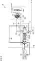
- Fig. 1 is a diagram schematically showing a configuration of an organic solvent recovery system 1A in an embodiment 1A.
- Organic solvent recovery system 1A includes a cooling/condensing apparatus 100, a concentrating apparatus 300, a first flow-through path F1, and a second flow-through path F2.
- Cooling/condensing apparatus 100 has a cooling portion 110, a separation portion 120, and a chamber 123.
- Exhaust gas G1 containing an organic solvent passes through cooling portion 110 and is accordingly cooled, with the result that the organic solvent is liquefied and condensed.
- exhaust gas G2 passes through separation portion 120 and is accordingly separated into liquefied/condensed cooled condensate liquid L1 and cooling treatment gas G3 in which the concentration of the organic solvent is reduced.
- part (adsorption inlet gas) G4 of the cooling treatment gas is distributed to be supplied to concentrating apparatus 300 through chamber 123, and is discharged from cooling/condensing apparatus 100.
- Cooling means and configuration of cooling portion 110 are not particularly limited, but may be a first heat exchanger 111 or the like that performs cooling by indirect heat exchange between the exhaust gas and refrigerant such as cooling water, cold water, or brine. Conditions such as a cooling temperature may be appropriately determined in accordance with the organic solvent to be recovered.
- a second heat exchanger 112 may be provided to precede first heat exchanger 111 so as to cool exhaust gas G1 by heat exchange between a remainder (return gas) G6 of the cooling treatment gas and exhaust gas G1. This is because heat transfer area and amount of refrigerant required for first heat exchanger 111 are reduced.
- Separation means and configuration of separation portion 120 are not particularly limited, and may be a reticulated structure 121 that captures droplets when exposed to droplets, such as a demister, a filter, or a mesh. Cooled condensate liquid L1 captured in reticulated structure 121 is collected by gravity into a tank 125 disposed below reticulated structure 121, and is recovered as recovered liquid L3.
- Chamber 123 is a structure having a certain volume of space.
- the cooling treatment gas is divided into part (adsorption inlet gas) G4 of the cooling treatment gas to be supplied to concentrating apparatus 300 and remainder (return gas) G6 of the cooling treatment gas.
- Chamber 123 has a partition portion 128 that enables suction of the cooling treatment gas into first flow-through path F1 in a direction opposite to the discharging direction of cooling treatment gas G3 discharged from reticulated structure 121.
- Concentrating apparatus 300 has an adsorption element 310 including an adsorption material that adsorbs the organic solvent contained in the gas when exposed to the gas and that desorbs the adsorbed organic solvent when exposed to heated gas. Further, adsorption element 310 includes a desorption portion (desorption zone) 311 and an adsorption portion (adsorption zone) 312. In adsorption portion 312, when part (adsorption inlet gas) G4 of the cooling treatment gas is introduced, the adsorption material is exposed to part (adsorption inlet gas) G4 of the cooling treatment gas, with the result that the organic solvent contained in part (adsorption inlet gas) G4 of the cooling treatment gas is adsorbed in the adsorption material. Accordingly, part (adsorption inlet gas) G4 of the cooling treatment gas is cleaned and clean gas G9 is discharged.
- desorption portion 311 when gas G10 having a temperature higher than that of part (adsorption inlet gas) G4 of the cooling treatment gas is introduced into the adsorption material, the organic solvent is desorbed from the adsorption material, with the result that desorption gas G11 containing the organic solvent is discharged.
- activated alumina, silica gel, activated carbon material or zeolite have been widely used.
- activated carbon and hydrophobic zeolite are particularly suitably used.
- the activated carbon and hydrophobic zeolite are excellent in terms of a function of adsorbing and desorbing a low-concentration organic compound, and have been conventionally used as an adsorption material in various types of apparatuses.
- the concentrating apparatus includes a rotation shaft and an adsorption element 310 provided around the rotation shaft, wherein when adsorption element 310 is rotated with respect to the rotation shaft, the adsorption material having adsorbed the organic solvent contained in part (adsorption inlet gas) G4 of the cooling treatment gas is continuously moved to desorption portion 311 in adsorption portion 312.
- desorption portion 311 is preferably disposed below adsorption portion 312 as shown in Fig. 1 . This is due to the following reason: even when part of the organic solvent contained in desorption gas G11 is liquefied and condensed to generate desorbed condensate liquid L2, desorbed condensate liquid L2 is less likely to be adhered to adsorption portion 312. Desorbed condensate liquid L2 falls downward from desorption portion 311, and is recovered along the inner surface of the exterior of the desorption portion or the like. More preferably, as shown in Fig. 1 , desorption portion 311 is inclined downward. This is because desorbed condensate liquid L2 is more likely to fall downward.
- Concentrating apparatus 300 may have a purging portion (not shown) to which a portion of the adsorption material having completed the desorption treatment in desorption portion 311 is moved before being moved to adsorption portion 312. Part of clean gas G9 may be introduced into the purging portion, and purging portion outlet gas discharged from the purging portion may be introduced into adsorption portion 312. This is due to the following reason: by purging the adsorption material having completed the desorption with clean gas G9, desorption gas G11 remaining in the adsorption material can be prevented from being mixed into clean gas G9 and the adsorption material can be cooled.
- high-temperature gas G10 used for the desorption is preferably gas obtained by heating part of clean gas G9 to have a high temperature by using heating means such as a regenerative heater 350. This is because an amount of the organic-solvent-containing gas to be treated is not increased in adsorption portion 312.
- a regenerative heater 350 When exhaust gas G1 has a temperature of 50 to 200°C, part of exhaust gas G1 is more preferably heated by regenerative heater 350 or the like for the sake of use. This is due to the following reason: by using exhaust gas G1 having a high temperature for the desorption, utility of regenerative heater 350 can be decreased, with the result that regenerative heater 350 becomes unnecessary for the desorption depending on the temperature of exhaust gas G1.
- a ratio at which exhaust gas G1 is permitted to pass to cooling/condensing apparatus 100 is assumed to be 0% to 50%, whereas a ratio at which desorption gas G11 is permitted to pass to cooling/condensing apparatus 100 is assumed to be 50% to 100%.
- First flow-through path F1 is a region through which part (adsorption inlet gas) G4 of the cooling treatment gas is introduced from chamber 123 to concentrating apparatus 300.
- a connection opening of first flow-through path F1 to chamber 123 is preferably a ceiling portion 127 of chamber 123. This is due to the following reason: a small amount of droplets that could not be captured by separation portion 120 are suppressed from entering concentrating apparatus 300 so as to prevent performance and strength from being decreased due to wetting of below-described adsorption element 310 of concentrating apparatus 300.
- partition portion 128 is provided to draw part (adsorption inlet gas) G4 of the cooling treatment gas in a direction opposite to the gas-flow direction of cooling treatment gas G3. The entrance of droplets can be further prevented.
- a droplet entrance prevention member similar to reticulated structure 121 described above may be provided at a drawing opening for part (adsorption inlet gas) G4 of the cooling treatment gas, or a heater may be provided to vaporize droplets.
- Second flow-through path F2 is a region through which desorption gas G11 is returned to an exhaust gas G1 introduction portion of cooling/condensing apparatus 100.
- Second flow-through path F2 is preferably connected thereto such that desorption portion 311 is disposed above a position of confluence of desorption gas G11 and exhaust gas G1 supplied to cooling/condensing apparatus 100. This is because desorbed condensate liquid L2 generated from desorption gas G11 of concentrating apparatus 300 is facilitated to be moved to cooling/condensing apparatus 100.
- second flow-through path F2 is configured to communicate with two positions of cooling/condensing apparatus 100, i.e., the exhaust gas G1 introduction portion and tank 125. This is because desorbed condensate liquid L2 generated from desorption gas G11 is facilitated to be recovered directly into tank 125.
- High-temperature gas G10 used for the desorption in concentrating apparatus 300 of organic solvent recovery system 1A in the embodiment is preferably gas obtained by heating part of clean gas G9 to have a high temperature using heating means such as regenerative heater 350 as described above; however, when exhaust gas G1 has a temperature of 50 to 200°C, part of exhaust gas G1 is more preferably heated by regenerative heater 350 or the like for the sake of use. This is due to the following reason: by using the exhaust gas having a high temperature for the desorption, utility of regenerative heater 350 can be decreased, with the result that regenerative heater 350 becomes unnecessary for the desorption depending on the temperature of exhaust gas G1.
- a ratio at which exhaust gas G1 is permitted to pass to cooling/condensing apparatus 100 is assumed to be 0% to 50%, whereas a ratio at which desorption gas G11 is permitted to pass to cooling/condensing apparatus 100 is assumed to be 50% to 100%.
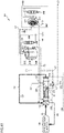
- a concentrating apparatus 500 may be additionally provided to treat remainder (return gas) G6 of the cooling treatment gas as shown in Fig. 2 .
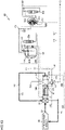
- a concentrating apparatus 600 may be additionally provided to treat clean gas G9 as shown in Fig. 3 .
- Each of concentrating apparatus 500 and concentrating apparatus 600 may be the same as or different from concentrating apparatus 300 in terms of configuration.
- the number of concentrating apparatuses additionally provided is not limited. Desorption gas discharged from any of the concentrating apparatuses is returned to the exhaust gas G1 introduction portion of cooling/condensing apparatus 100 via second flow-through path F2.
- the organic solvent contained in exhaust gas G1 is an organic solvent that can be liquefied and recovered by cooling at 1°C to 50°C.
- the organic solvent include N-methyl-2-pyrrolidone, N-ethyl-2-pyrrolidone, N,N-dimethylformamide, N,N-dimethylacetamide, and n-decane. These are illustrative and are not restrictive. One type or a plurality of types of organic solvents may be contained.
- Fig. 4 is a diagram schematically showing a configuration of an organic solvent recovery system 1B in an embodiment 1B.
- Organic solvent recovery system 1B includes a cooling/condensing apparatus 100, a first concentrating apparatus 200, a second concentrating apparatus 300, and various types of flow-through paths.
- Cooling/condensing apparatus 100 has a cooling portion 110 and a separation portion 120.
- Exhaust gas G1 containing an organic solvent is discharged from a production facility 130.
- Exhaust gas G1 passes through cooling portion 110 and is accordingly cooled. With the passage of exhaust gas G1 through cooling portion 110, the organic solvent is liquefied and condensed.
- Exhaust gas G2 having passed through cooling portion 110 passes through separation portion 120 and is accordingly separated into liquefied/condensed cooled condensate liquid L1 and cooling treatment gas G3 in which the concentration of the organic solvent is reduced.
- Cooling treatment gas G3 is discharged from cooling/condensing apparatus 100 to first concentrating apparatus 200 through chamber 123 as cooling treatment gas G4.
- Cooling means and configuration of cooling portion 110 are not particularly limited.
- a first heat exchanger 111 that performs cooling by indirect heat exchange between the exhaust gas and refrigerant such as cooling water, cold water, or brine is used.
- First heat exchanger 111 is positioned to allow exhaust gas G1 to flow in the upward/downward direction.
- cooling portion 110 a below-described second heat exchanger 112 is provided to precede first heat exchanger 111 so as to cool exhaust gas G1 by heat exchange between cooling treatment gas G6 and exhaust gas G1. With second heat exchanger 112, heat transfer area and amount of refrigerant required for first heat exchanger 111 can be reduced. Exhaust gas G1 and part of cooling treatment gas G6 are returned to production facility 130 through a fifth flow-through path F5. Conditions such as cooling temperatures in first heat exchanger 111 and second heat exchanger 112 may be appropriately determined in accordance with the organic solvent to be recovered.
- Separation means and configuration of separation portion 120 are not particularly limited.
- a reticulated structure 121 is used to capture droplets when exposed to the droplets, such as a demister, a filter, or a mesh.
- Separation portion 120 has a funnel-shaped receiving portion 122 that receives cooled condensate liquid L1 containing the organic solvent and cooled by cooling portion 110. Cooled condensate liquid L1 cooled by cooling portion 110 and cooled condensate liquid L1 captured in reticulated structure 121 flow into receiving portion 122 due to gravity, are then collected in tank 125 disposed below receiving portion 122, and are recovered as recovered liquid L3.
- Chamber 123 is a structure having a certain volume of space.
- a weir 124 is provided in chamber 123.
- Weir 124 prevents part of cooled condensate liquid L1 from being moved in a direction toward the front end of chamber 123 and from flowing through a first flow-through path F1 serving as a cooling gas flow-through path.
- Weir 124 serves to securely recover cooled condensate liquid L1.
- Cooling treatment gas G3 stored in chamber 123 for a certain period of time flows through first flow-through path F1 as cooling treatment gas G4, and is supplied to first concentrating apparatus 200.
- Organic solvent recovery system 1B is structured such that when viewed along a direction in which exhaust gas G1 flows, a direction of flow from reticulated structure 121 to chamber 123 in separation portion 120 intersects a direction of flow from cooling portion 110 to separation portion 120 so as to allow exhaust gas G1 (exhaust gas G2, cooling treatment gas G3) to flow in a direction of L shape.
- organic solvent recovery system 1B a portion constituted of cooling portion 110 and separation portion 120 has the L-shaped structure, so that first concentrating apparatus 200 and second concentrating apparatus 300 can be suppressed from being exposed to droplets or airborne droplets.
- first concentrating apparatus 200 and second concentrating apparatus 300 When each of first concentrating apparatus 200 and second concentrating apparatus 300 is exposed thereto and the adsorption material is accordingly wet, decreased strength or breakage may be resulted. Since organic solvent recovery system 1B has the L-shaped structure, each of first concentrating apparatus 200 and second concentrating apparatus 300 can be prevented from being decreased in strength and broken.
- First concentrating apparatus 200 has an adsorption rotor 212 including an adsorption material that adsorbs the organic solvent contained in the gas when exposed to the gas and that desorbs the adsorbed organic solvent when exposed to heated gas.
- Adsorption rotor 212 includes a plurality of adsorption units 210 partitioned by a plurality of partition portions. With the plurality of adsorption units 210, adsorption rotor 212 has a hollow cylindrical shape as a whole.
- Adsorption rotor 212 is installed in a treatment chamber and is provided to allow fluid to flow in a radial direction.
- Adsorption rotor 212 is provided to be rotatable with respect to a cylinder axis thereof by receiving rotational driving force of a motor.
- part of adsorption units 210 constitute an adsorption portion that adsorbs the organic solvent contained in cooling treatment gas G4 supplied from the outside of adsorption units 210 toward the inside of adsorption units 210, and the remainder of adsorption units 210 constitute a desorption portion that desorbs the organic solvent adsorbed in adsorption units 210 from adsorption units 210 by supplying heated air from the inside of adsorption units 210 toward the outside of adsorption units 210.
- cooling treatment gas G4 supplied into the treatment chamber is introduced into the adsorption portion from the outer peripheral surface of adsorption rotor 212.
- cooling treatment gas G4 introduced into the adsorption portion passes through adsorption rotor 212 from the outer peripheral surface toward the inner peripheral surface along the radial direction, cooling treatment gas G4 is cleaned by adsorbing the organic solvent in the plurality of adsorption units 210 located in the adsorption portion.
- Cooling treatment gas G5 and cooling treatment gas G6 each serving as cleaned and treated fluid are discharged as clean gas from the upper portions of adsorption units 210. Part of the discharged clean gas flows through a second flow-through path F2 as cooling treatment gas G5 and is supplied to second concentrating apparatus 300. Part of the discharged clean gas flows through a fourth flow-through path F4 as cooling treatment gas G6, and is returned to second heat exchanger 112.
- An inner peripheral side flow path forming member 211 and an outer peripheral side flow path forming member 213 are arranged to face each other on the inner peripheral side and outer peripheral side of adsorption rotor 212 so as to sandwich a portion of adsorption rotor 212 in the peripheral direction.
- a region of adsorption rotor 212 sandwiched by inner peripheral side flow path forming member 211 and outer peripheral side flow path forming member 213 is the desorption portion.
- high-temperature gas G7 which is obtained by heating part of cooling treatment gas G5 using a regenerative heater 250, is introduced from inner peripheral side flow path forming member 211 to the desorption portion.
- high-temperature gas G7 introduced into the desorption portion passes through adsorption rotor 212, the organic solvent adsorbed in the plurality of adsorption units 210 located in the desorption portion is desorbed by heat from the plurality of adsorption units 210.
- Desorption gas G8 containing the organic solvent is discharged as concentrated gas from the desorption portion to the outside of the treatment chamber through outer peripheral side flow path forming member 213 and is returned to a third flow-through path F3. Part of the organic solvent contained in desorption gas G8 is liquefied and condensed and is collected in tank 125 as desorbed condensate liquid L2.
- Third flow-through path F3 is a region through which desorption gas G8 and below-described desorption gas G11 are returned to the exhaust gas G1 introduction portion of cooling/condensing apparatus 100.
- Third flow-through path F3 is preferably connected thereto such that the desorption portion is disposed above a position of confluence of the desorption gas and exhaust gas G1 supplied to cooling/condensing apparatus 100. This is because desorbed condensate liquid L2 generated from desorption gas G8 of first concentrating apparatus 200 and desorption gas G11 of second concentrating apparatus 300 is facilitated to be moved to cooling/condensing apparatus 100.
- Third flow-through path F3 is preferably configured to communicate with two positions of cooling/condensing apparatus 100, i.e., the exhaust gas G1 introduction portion and tank 125. This is because desorbed condensate liquid L2 generated from desorption gas G8 and desorption gas G11 is facilitated to be recovered directly into tank 125.
- first concentrating apparatus 200 the adsorption treatment for the target substance is performed on adsorption units 210 located in the adsorption portion, and the desorption treatment for the target substance is performed on adsorption units 210 located in the desorption portion after the adsorption treatment. Since adsorption rotor 212 is rotated with respect to the cylinder axis, each adsorption unit 210 is moved alternately between the desorption portion and the adsorption portion, thereby continuously performing the adsorption treatment and desorption treatment for the target substance.
- a material of the adsorption element included in adsorption unit 210 activated alumina, silica gel, activated carbon material, zeolite, or the like can be used.
- the shape of the adsorption element in adsorption unit 210 is not particularly limited, and may be, for example, as follows: a sheet containing the activated carbon material or zeolite is formed in the form of a honeycomb, or activated carbon fiber nonwoven fabrics are layered.
- Second concentrating apparatus 300 has an adsorption element 310 including an adsorption material that adsorbs the organic solvent contained in the gas when exposed to the gas and that desorbs the adsorbed organic solvent when exposed to heated gas.
- Adsorption element 310 includes a desorption portion (desorption zone) 311 and an adsorption portion (adsorption zone) 312.
- adsorption portion 312 when cooling treatment gas G5 is introduced, the adsorption material is exposed to cooling treatment gas G5, with the result that the organic solvent contained in cooling treatment gas G5 is adsorbed in the adsorption material. Accordingly, cooling treatment gas G5 is cleaned and clean gas G9 is discharged.
- desorption portion 311 when high-temperature gas G10 having a temperature higher than that of cooling treatment gas G5 is introduced into the adsorption material, the organic solvent is desorbed from the adsorption material, with the result that desorption gas G11 containing the organic solvent is discharged.
- activated alumina, silica gel, activated carbon material and zeolite have been widely used. Among them, activated carbon and hydrophobic zeolite are particularly suitably used.
- second concentrating apparatus 300 includes a rotation shaft and an adsorption element 310 provided around the rotation shaft. Second concentrating apparatus 300 is configured to rotate adsorption element 310 with respect to the rotation shaft so as to continuously move, to desorption portion 311, the adsorption material having adsorbed the organic solvent contained in cooling treatment gas G5 introduced from second flow-through path F2 in adsorption portion 312.
- desorption portion 311 is preferably disposed below adsorption portion 312 as shown in Fig. 4 . This is due to the following reason: even when part of the organic solvent contained in desorption gas G11 is liquefied and condensed to generate desorbed condensate liquid L2, desorbed condensate liquid L2 is less likely to be adhered to adsorption portion 312. Desorbed condensate liquid L2 falls downward from desorption portion 311 and is recovered along the inner surface of the exterior of the desorption portion or the like. More preferably, desorption portion 311 is inclined downward in order to further facilitate desorbed condensate liquid L2 to fall downward.
- Second concentrating apparatus 300 may have a cleaning portion (purging portion) to which a portion of the adsorption material having completed the desorption treatment in desorption portion 311 is moved before being moved to adsorption portion 312.
- a cleaning portion prurging portion
- purging portion outlet gas discharged from the purging portion may be introduced into adsorption portion 312. This is due to the following reason: by cleaning the adsorption material having completed the desorption with clean gas G9, desorption gas G11 remaining in the adsorption material can be prevented from being mixed into clean gas G9 and the adsorption material can be cooled.
- High-temperature gas G10 used for the desorption is preferably gas obtained by heating part of clean gas G9 to have a high temperature by using heating means such as a regenerative heater 350. This is because an amount of the organic-solvent-containing gas to be treated is not increased in adsorption portion 312.
- Fig. 5 is a diagram schematically showing a configuration of an organic solvent recovery system 2B in an embodiment 2B.
- Organic solvent recovery system 2B includes a cooling/condensing apparatus 100, a first concentrating apparatus 200, a second concentrating apparatus 300, and various types of flow-through paths.
- Organic solvent recovery system 2B is the same as organic solvent recovery system 1B of embodiment 1B except that a heater 126 is provided in chamber 123.
- Heater 126 slightly heats cooled cooling treatment gas G3. Since cooling treatment gas G3 is slightly heated, the organic solvent or moisture can be prevented from being condensed.
- Cooling/condensing apparatus 100 in the present embodiment includes: cooling portion 110 through which exhaust gas G1 flows; and separation portion 120 located on the downstream side with respect to cooling portion 110 when viewed along the direction in which exhaust gas G1 flows.
- Separation portion 120 has: receiving portion 122 that receives cooled condensate liquid L1 containing the organic solvent and cooled by cooling portion 110; reticulated structure 121 that separates cooled exhaust gas G2 into cooled condensate liquid L1 and cooling treatment gas G3 when exposed to cooled exhaust gas G2; and chamber 123 that stores, for a certain period of time, cooling treatment gas G3 after passing through reticulated structure 121.
- cooled condensate liquid L1 containing the organic solvent can be recovered from exhaust gas G1 more efficiently.
- a portion constituted of cooling portion 110 and separation portion 120 has the L-shaped structure, so that first concentrating apparatus 200 and second concentrating apparatus 300 provided at subsequent stages can be suppressed from being exposed to droplets or airborne droplets.
- Heater 126 is disposed on the downstream side with respect to reticulated structure 121 in the present embodiment so as to heat cooling treatment gas G3.
- cooling treatment gas G3 is slightly heated, the organic solvent or moisture can be prevented from being condensed.
- weir 124 is provided in chamber 123 in the present embodiment.
- cooled condensate liquid L1 can be prevented from flowing into first flow-through path F 1 serving as the cooling gas flow-through path.
- the concentrating apparatus in the present embodiment includes first concentrating apparatus 200 and second concentrating apparatus 300 located on the downstream side with respect to first concentrating apparatus 200.
- First concentrating apparatus 200 adsorbs, in adsorption units 210, the organic solvent contained in cooling treatment gas G4 introduced from first flow-through path F1 and discharges cooling treatment gas G5 in which the concentration of the organic solvent is further reduced, and introduces high-temperature gas G7 to desorb the organic solvent from adsorption units 210 and discharges desorption gas G8.
- the organic solvent recovery system in the present embodiment further includes second flow-through path F2 through which part of cooling treatment gas G5 flows, wherein second concentrating apparatus 300 absorbs, in adsorption element 310, the organic solvent contained in cooling treatment gas G5 introduced from second flow-through path F2 and discharges clean gas G9 in which the concentration of the organic solvent is further reduced, and introduces high-temperature gas G10 to desorb the organic solvent from adsorption element 310 and discharges desorption gas G11.
- the plurality of adsorption units 210 are disposed in the peripheral direction with respect to the cylinder axis of the rotor that is rotatable with respect to the cylinder axis, the rotor having a hollow cylindrical shape.
- the organic solvent can be recovered with high efficiency.
- adsorption element 310 is disposed on the adsorption rotor that is rotatable with respect to the cylinder axis of the adsorption rotor, the adsorption rotor having a shape of disk.
- the organic solvent can be recovered with high efficiency.
- the concentrating apparatus employs the two concentrating apparatuses, i.e., first concentrating apparatus 200 and second concentrating apparatus 300.
- the concentrating apparatus may employ two first concentrating apparatuses 200 or two second concentrating apparatuses 300 in accordance with an amount of gas. Further, three or more concentrating apparatuses may be employed in accordance with removal efficiency.
- the organic solvent contained in exhaust gas G1 is an organic solvent that can be liquefied and recovered by cooling at 1°C to 50°C.
- the organic solvent include N-methyl-2-pyrrolidone, N-ethyl-2-pyrrolidone, N,N-dimethylformamide, N,N-dimethylacetamide, and n-decane. These are illustrative and not restrictive. One type or a plurality of types of organic solvents may be contained.
- Fig. 6 is a diagram schematically showing a configuration of an organic solvent recovery system 1C in an embodiment 1C.
- Organic solvent recovery system 1C includes a cooling/condensing apparatus 100, a first concentrating apparatus 200, a second concentrating apparatus 300, and various types of flow-through paths.
- Cooling/condensing apparatus 100 includes a cooling portion 110 and a separation portion 120.
- Exhaust gas G1 containing an organic solvent is discharged from a production facility 130.
- Exhaust gas G1 passes through cooling portion 110 and is accordingly cooled. With the passage of exhaust gas G1 through cooling portion 110, the organic solvent is liquefied and condensed.
- Exhaust gas G2 having passed through cooling portion 110 passes through separation portion 120 and is accordingly separated into liquefied/condensed cooled condensate liquid L1 and cooling treatment gas G3 in which the concentration of the organic solvent is reduced.
- Cooling treatment gas G3 is discharged from cooling/condensing apparatus 100 to first concentrating apparatus 200 through chamber 123 as cooling treatment gas G4.
- Cooling means and configuration of cooling portion 110 are not particularly limited.
- a first heat exchanger 111 that performs cooling by indirect heat exchange between the exhaust gas and refrigerant such as cooling water, cold water, or brine is used.
- First heat exchanger 111 is positioned to allow exhaust gas G1 to flow in the horizontal direction.
- cooling portion 110 a below-described second heat exchanger 112 is provided to precede first heat exchanger 111 so as to cool exhaust gas G1 by heat exchange between cooling treatment gas G6 and exhaust gas G1. With second heat exchanger 112, heat transfer area and amount of refrigerant required for first heat exchanger 111 can be reduced. Exhaust gas G1 and part of cooling treatment gas G6 are returned to production facility 130 through a fifth flow-through path F5. Conditions such as cooling temperatures in first heat exchanger 111 and second heat exchanger 112 may be appropriately determined in accordance with the organic solvent to be recovered.
- Separation means and configuration of separation portion 120 are not particularly limited.
- a reticulated structure 121 is used to capture droplets when exposed to the droplets, such as a demister, a filter, or a mesh. Cooled condensate liquid L1 captured in reticulated structure 121 is collected by gravity into a tank 125 disposed below reticulated structure 121, and is recovered as recovered liquid L3.
- Chamber 123 is a structure having a certain volume of space. Cooling treatment gas G3 stored in chamber 123 for a certain period of time flows through a first flow-through path F1 as cooling treatment gas G4, and is supplied to first concentrating apparatus 200. Chamber 123 has a partition portion 128 that enables suction of the cooling treatment gas into first flow-through path F1 in a direction opposite to the discharging direction of cooling treatment gas G3 discharged from reticulated structure 121.
- First flow-through path F1 is a region through which cooling treatment gas G4 is introduced from chamber 123 to first concentrating apparatus 200.
- a connection opening of first flow-through path F1 to chamber 123 is preferably a ceiling portion 127 of chamber 123. Accordingly, a small amount of droplets that could not be captured by separation portion 120 are suppressed from entering first concentrating apparatus 200 so as to prevent performance and strength from being decreased due to wetting of a below-described adsorption unit 210 of first concentrating apparatus 200.
- cooling treatment gas G4 is drawn in a direction opposite to the gas-flow direction of cooling treatment gas G3. Thus, the entrance of droplets can be further prevented.
- a droplet entrance prevention member similar to reticulated structure 121 described above may be provided at a drawing opening for cooling treatment gas G4, or a heater may be provided to vaporize droplets.
- First concentrating apparatus 200 has an adsorption rotor 212 including an adsorption material that adsorbs the organic solvent contained in the gas when exposed to the gas and that desorbs the adsorbed organic solvent when exposed to heated gas.
- Adsorption rotor 212 includes a plurality of adsorption units 210 partitioned by a plurality of partition portions. With the plurality of adsorption units 210, adsorption rotor 212 has a hollow cylindrical shape as a whole.
- Adsorption rotor 212 is installed in a treatment chamber and is provided to allow fluid to flow in a radial direction.
- Adsorption rotor 212 is provided to be rotatable with respect to a cylinder axis thereof by receiving rotational driving force of a motor.
- part of adsorption units 210 constitute an adsorption portion that adsorbs the organic solvent contained in cooling treatment gas G4 supplied from the outside of adsorption units 210 toward the inside of adsorption units 210, and the remainder of adsorption units 210 constitute a desorption portion that desorbs the organic solvent adsorbed in adsorption units 210 from adsorption units 210 by supplying heated air from the inside of adsorption units 210 toward the outside of adsorption units 210.
- cooling treatment gas G4 supplied into the treatment chamber is introduced into the adsorption portion from the outer peripheral surface of adsorption rotor 212.
- cooling treatment gas G4 introduced into the adsorption portion passes through adsorption rotor 212 from the outer peripheral surface toward the inner peripheral surface along the radial direction, cooling treatment gas G4 is cleaned by adsorbing the organic solvent in the plurality of adsorption units 210 located in the adsorption portion.
- Cooling treatment gas G5 and cooling treatment gas G6 each serving as cleaned and treated fluid are discharged as clean gas from the upper portions of adsorption units 210. Part of the discharged clean gas flows through a second flow-through path F2 as cooling treatment gas G5 and is supplied to second concentrating apparatus 300. Part of the discharged clean gas flows through a fourth flow-through path F4 as cooling treatment gas G6, and is returned to second heat exchanger 112.
- An inner peripheral side flow path forming member 211 and an outer peripheral side flow path forming member 213 are arranged to face each other on the inner peripheral side and outer peripheral side of adsorption rotor 212 so as to sandwich a portion of adsorption rotor 212 in the peripheral direction.
- a region of adsorption rotor 212 sandwiched between inner peripheral side flow path forming member 211 and outer peripheral side flow path forming member 213 is the desorption portion.
- high-temperature gas G7 which is obtained by heating part of cooling treatment gas G5 using regenerative heater 250, is introduced from inner peripheral side flow path forming member 211 to the desorption portion.
- high-temperature gas G7 introduced into the desorption portion passes through adsorption rotor 212, the organic solvent adsorbed in the plurality of adsorption units 210 located in the desorption portion is desorbed by heat from the plurality of adsorption units 210.
- Desorption gas G8 containing the organic solvent is discharged as concentrated gas from the desorption portion to the outside of the treatment chamber through outer peripheral side flow path forming member 213 and is returned to a third flow-through path F3. Part of the organic solvent contained in desorption gas G8 is liquefied and condensed and is collected in tank 125 as desorbed condensate liquid L2.
- Third flow-through path F3 is a region through desorption gas G8 is returned to the exhaust gas G1 introduction portion of cooling/condensing apparatus 100.
- Third flow-through path F3 is preferably connected thereto such that the desorption portion is disposed above a position of confluence of desorption gas G8 and exhaust gas G1 supplied to cooling/condensing apparatus 100. With this configuration, desorbed condensate liquid L2 generated from desorption gas G8 of first concentrating apparatus 200 is facilitated to be moved to cooling/condensing apparatus 100.
- Third flow-through path F3 is preferably configured to communicate with two positions of cooling/condensing apparatus 100, i.e., the exhaust gas G1 introduction portion and tank 125. With this configuration, desorbed condensate liquid L2 generated from desorption gas G8 is facilitated to be recovered directly into tank 125.
- first concentrating apparatus 200 the adsorption treatment for the target substance is performed on adsorption units 210 located in the adsorption portion, and the desorption treatment for the target substance is performed on adsorption units 210 located in the desorption portion after the adsorption treatment. Since adsorption rotor 212 is rotated with respect to the cylinder axis, each adsorption unit 210 is moved alternately between the desorption portion and the adsorption portion, thereby continuously performing the adsorption treatment and desorption treatment for the target substance.
- a material of the adsorption element included in adsorption unit 210 activated alumina, silica gel, activated carbon material, zeolite, or the like can be used.
- the shape of the adsorption element in adsorption unit 210 is not particularly limited, and may be, for example, as follows: a sheet containing the activated carbon material or zeolite is formed in the form of a honeycomb, or activated carbon fiber nonwoven fabrics are layered.
- Second concentrating apparatus 300 has an adsorption element 310 including an adsorption material that adsorbs the organic solvent contained in the gas when exposed to the gas and that desorbs the adsorbed organic solvent when exposed to heated gas.
- Adsorption element 310 includes a desorption portion (desorption zone) 311 and an adsorption portion (adsorption zone) 312.
- adsorption portion 312 when cooling treatment gas G5 is introduced, the adsorption material is exposed to cooling treatment gas G5, with the result that the organic solvent contained in cooling treatment gas G5 is adsorbed in the adsorption material. Accordingly, cooling treatment gas G5 is cleaned and clean gas G9 is discharged.
- desorption portion 311 when high-temperature gas G10 having a temperature higher than that of cooling treatment gas G5 is introduced into the adsorption material, the organic solvent is desorbed from the adsorption material, with the result that desorption gas G11 containing the organic solvent is discharged. Desorption gas G11 is returned to first flow-through path F1 through a sixth flow-through path F6.
- organic solvent recovery system 1C desorption gas G11 is returned to first flow-through path F1, so that it is not necessary to treat an amount of gas corresponding to desorption gas G11 in cooling/condensing apparatus 100. Therefore, organic solvent recovery system 1C can contribute to downsizing and energy saving of cooling/condensing apparatus 100. Since desorption gas G11 has a high temperature, NMP (N-methyl-2-pyrrolidone), moisture, or the like contained in cooling treatment gas G4 can be suppressed from being condensed in organic solvent recovery system 1C.
- NMP N-methyl-2-pyrrolidone
- activated alumina, silica gel, activated carbon material and zeolite have been widely used. Among them, activated carbon and hydrophobic zeolite are particularly suitably used.
- second concentrating apparatus 300 includes a rotation shaft and an adsorption element 310 provided around the rotation shaft. Second concentrating apparatus 300 is configured to rotate adsorption element 310 with respect to the rotation axis so as to continuously move, to desorption portion 311, the adsorption material having adsorbed the organic solvent contained in cooling treatment gas G5 introduced from second flow-through path F2 in adsorption portion 312.
- Second concentrating apparatus 300 may have a cleaning portion (purging portion) to which a portion of the adsorption material having completed the desorption treatment in desorption portion 311 is moved before being moved to adsorption portion 312.
- a cleaning portion prurging portion
- purging portion outlet gas discharged from the purging portion may be introduced into adsorption portion 312. This is due to the following reason: by cleaning the adsorption material having completed the desorption with clean gas G9, desorption gas G11 remaining in the adsorption material can be prevented from being mixed into clean gas G9 and the adsorption material can be cooled.
- High-temperature gas G10 used for the desorption is preferably gas obtained by heating part of clean gas G9 to have a high temperature by using heating means such as a regenerative heater 350. With the high temperature, an amount of the organic-solvent-containing gas to be treated is suppressed from being increased in adsorption portion 312.
- Fig. 7 is a diagram schematically showing a configuration of an organic solvent recovery system 2C in an embodiment 2C.
- Organic solvent recovery system 2C includes a cooling/condensing apparatus 100, a first concentrating apparatus 200, a second concentrating apparatus 300, and various types of flow-through paths.
- Organic solvent recovery system 2C is the same as organic solvent recovery system 1C of embodiment 1C except that desorption gas G11 of second concentrating apparatus 300 is returned to regenerative heater 250 through sixth flow-through path F6.
- organic solvent recovery system 2C desorption gas G11 is returned to regenerative heater 250, so that it is not necessary to treat an amount of gas corresponding to desorption gas G11 in cooling/condensing apparatus 100 and first concentrating apparatus 200. Therefore, organic solvent recovery system 2C can contribute to downsizing and energy saving of cooling/condensing apparatus 100 and first concentrating apparatus 200. Since desorption gas G11 has a high temperature, organic solvent recovery system 2C can contribute to energy saving of regenerative heater 250.
- Fig. 8 is a diagram schematically showing a configuration of an organic solvent recovery system 3C in an embodiment 3C.
- Organic solvent recovery system 3C includes a cooling/condensing apparatus 100, a first concentrating apparatus 200, a second concentrating apparatus 300, and various types of flow-through paths.
- desorption gas G11 of second concentrating apparatus 300 is returned to fourth flow-through path F4 through sixth flow-through path F6.
- Organic solvent recovery system 3C is the same as organic solvent recovery system 1C of embodiment 1C except that desorption gas G11 of second concentrating apparatus 300 is returned to fourth flow-through path F4 through sixth flow-through path F6.
- Desorption gas G11 having flowed through sixth flow-through path F6 flows through fourth flow-through path F4 together with cooling treatment gas G6 discharged from second concentrating apparatus 300 and is returned to second heat exchanger 112.
- organic solvent recovery system 3C it is not necessary to treat an amount of gas corresponding to desorption gas G11 in cooling/condensing apparatus 100 and first concentrating apparatus 200. Therefore, organic solvent recovery system 3C can contribute to downsizing and energy saving of cooling/condensing apparatus 100 and first concentrating apparatus 200.
- desorption gas G11 has a high temperature, so that the temperature of the fluid flowing through second heat exchanger 112 can be increased, thereby contributing to downsizing and energy saving of second heat exchanger 112 for cooling exhaust gas G1.
- Fig. 9 is a diagram schematically showing a configuration of an organic solvent recovery system 4C in an embodiment 4C.
- Organic solvent recovery system 4C includes a cooling/condensing apparatus 100, a first concentrating apparatus 200, a second concentrating apparatus 300, and various types of flow-through paths.
- desorption gas G11 of second concentrating apparatus 300 is returned to fifth flow-through path F5 through sixth flow-through path F6.
- Organic solvent recovery system 4C is the same as organic solvent recovery system 1C of embodiment 1C except that desorption gas G11 of second concentrating apparatus 300 is returned to fifth flow-through path F5 through sixth flow-through path F6.
- Desorption gas G11 having flowed through sixth flow-through path F6 flows through fifth flow-through path F5 together with exhaust gas G1 discharged from second heat exchanger 112 and part of cooling treatment gas G6, and is returned to production facility 130.
- organic solvent recovery system 4C it is not necessary to treat an amount of gas corresponding to desorption gas G11 in cooling/condensing apparatus 100 and first concentrating apparatus 200. Therefore, organic solvent recovery system 4C can contribute to downsizing and energy saving of cooling/condensing apparatus 100 and first concentrating apparatus 200.
- desorption gas G11 has a high temperature, so that the temperature of exhaust gas G1 discharged again from production facility 130 can be increased. Therefore, the temperature of the fluid flowing through second heat exchanger 112 can be increased in organic solvent recovery system 4C, thereby contributing to downsizing and energy saving of second heat exchanger 112 for cooling exhaust gas G1.
- Organic solvent recovery system 1C in the present embodiment includes: cooling/condensing apparatus 100 that cools exhaust gas G1 containing an organic solvent to liquefy and condense the organic solvent and discharges cooling treatment gas G4 in which the concentration of the organic solvent is reduced; first flow-through path F1 through which cooling treatment gas G4 flows; and first concentrating apparatus 200 that adsorbs, in adsorption unit 210, the organic solvent contained in cooling treatment gas G4 introduced from first flow-through path F1 and discharges cooling treatment gas G5 in which the concentration of the organic solvent is further reduced and that introduces high-temperature gas G7 to desorb the organic solvent from adsorption unit 210 and discharges desorption gas G8; second flow-through path F2 through which part of cooling treatment gas G5 flows; and second concentrating apparatus 300 that absorbs, in adsorption element 310, the organic solvent contained in cooling treatment gas G5 introduced from second flow-through path F2 and discharges clean gas G9 in which the concentration of the organic solvent is further reduced and that introduces high-temperatur
- Desorption gas G8 is returned to cooling/condensing apparatus 100, and desorption gas G11 is returned to first flow-through path F1.
- desorption gas G11 is returned to first flow-through path F1, so that it is not necessary to treat an amount of gas corresponding to desorption gas G11 in cooling/condensing apparatus 100. Therefore, organic solvent recovery system 1C can contribute to downsizing and energy saving of cooling/condensing apparatus 100. Since desorption gas G11 has a high temperature, NMP (N-methyl-2-pyrrolidone), moisture, or the like contained in cooling treatment gas G4 can be suppressed from being condensed in organic solvent recovery system 1C.
- NMP N-methyl-2-pyrrolidone
- Desorption gas G8 is returned to cooling/condensing apparatus 100, and desorption gas G11 is returned to regenerative heater 250.
- organic solvent recovery system 2C desorption gas G11 is returned to regenerative heater 250, so that it is not necessary to treat an amount of gas corresponding to desorption gas G11 in cooling/condensing apparatus 100 and first concentrating apparatus 200. Therefore, organic solvent recovery system 2C can contribute to downsizing and energy saving of cooling/condensing apparatus 100 and first concentrating apparatus 200. Since desorption gas G11 has a high temperature, organic solvent recovery system 2C can contribute to energy saving of regenerative heater 250.
- Desorption gas G8 is returned to cooling/condensing apparatus 100, and desorption gas G11 is returned to fourth flow-through path F4. Desorption gas G11 flows through fourth flow-through path F4 together with cooling treatment gas G6, and is returned to second heat exchanger 112.
- organic solvent recovery system 3C it is not necessary to treat an amount of gas corresponding to desorption gas G11 in cooling/condensing apparatus 100 and first concentrating apparatus 200. Therefore, organic solvent recovery system 3C can contribute to downsizing and energy saving of cooling/condensing apparatus 100 and first concentrating apparatus 200.
- desorption gas G11 has a high temperature, so that the temperature of the fluid flowing through second heat exchanger 112 can be increased, thereby contributing to downsizing and energy saving of second heat exchanger 112 for cooling exhaust gas G1.
- Desorption gas G8 is returned to cooling/condensing apparatus 100, and desorption gas G11 is returned to fifth flow-through path F5.
- Desorption gas G11 flows through fifth flow-through path F5 together with exhaust gas G1 discharged from second heat exchanger 112 and part of cooling treatment gas G6, and is returned to production facility 130.
- organic solvent recovery system 4C it is not necessary to treat an amount of gas corresponding to desorption gas G11 in cooling/condensing apparatus 100 and first concentrating apparatus 200. Therefore, organic solvent recovery system 4C can contribute to downsizing and energy saving of cooling/condensing apparatus 100 and first concentrating apparatus 200.
- desorption gas G11 has a high temperature, so that the temperature of exhaust gas G1 discharged again from production facility 130 can be increased. Therefore, the temperature of the fluid flowing through second heat exchanger 112 can be increased in organic solvent recovery system 4C, thereby contributing to downsizing and energy saving of second heat exchanger 112 for cooling exhaust gas G1.
- the plurality of adsorption units 210 are disposed in the peripheral direction with respect to the cylinder axis of the rotor that is rotatable with respect to the cylinder axis, the rotor having a hollow cylindrical shape.
- the organic solvent can be recovered with high efficiency.
- adsorption element 310 is disposed on the adsorption rotor that is rotatable with respect to the cylinder axis of the adsorption rotor, the adsorption rotor having a shape of disk.
- the organic solvent can be recovered with high efficiency.
- the concentrating apparatus employs the two concentrating apparatuses, i.e., first concentrating apparatus 200 and second concentrating apparatus 300.
- the concentrating apparatus may employ two first concentrating apparatuses 200 or two second concentrating apparatuses 300 in accordance with an amount of gas. Further, three or more concentrating apparatuses may be employed in accordance with removal efficiency.
- the organic solvent contained in exhaust gas G1 is an organic solvent that can be liquefied and recovered by cooling at 1°C to 50°C.
- the organic solvent include N-methyl-2-pyrrolidone, N-ethyl-2-pyrrolidone, N,N-dimethylformamide, N,N-dimethylacetamide, and n-decane. These are illustrative and not restrictive. One type or a plurality of types of organic solvents may be contained.
- Fig. 10 is a diagram schematically showing a configuration of an organic solvent recovery system 1D in an embodiment 1D.
- Organic solvent recovery system 1D includes a cooling/condensing apparatus 100, a first concentrating apparatus 200, a second concentrating apparatus 300, and various types of flow-through paths.
- Cooling/condensing apparatus 100 includes a cooling portion 110 and a separation portion 120.
- Exhaust gas G1 containing an organic solvent is discharged from a production facility 130.
- Exhaust gas G1 passes through cooling portion 110 and is accordingly cooled. With the passage of exhaust gas G1 through cooling portion 110, the organic solvent is liquefied and condensed.
- Exhaust gas G2 having passed through cooling portion 110 passes through separation portion 120 and is accordingly separated into liquefied/condensed cooled condensate liquid L1 and cooling treatment gas G3 in which the concentration of the organic solvent is reduced.
- Part of cooling treatment gas G3 is discharged from cooling/condensing apparatus 100 to first concentrating apparatus 200 through chamber 123 as cooling treatment gas G4, and a remainder of cooling treatment gas G3 is returned from cooling/condensing apparatus 100 to a below-described second heat exchanger 112 as cooling treatment gas G6.
- Cooling means and configuration of cooling portion 110 are not particularly limited.
- a first heat exchanger 111 that performs cooling by indirect heat exchange between the exhaust gas and refrigerant such as cooling water, cold water, or brine is used.
- First heat exchanger 111 is positioned to allow exhaust gas G1 to flow in the horizontal direction.
- second heat exchanger 112 is provided to precede first heat exchanger 111 so as to cool exhaust gas G1 by heat exchange between cooling treatment gas G6 and exhaust gas G1. With second heat exchanger 112, heat transfer area and amount of refrigerant required for first heat exchanger 111 can be reduced. Exhaust gas G1 and part of cooling treatment gas G6 are returned to production facility 130 through fifth flow-through path F5. Conditions such as cooling temperatures in first heat exchanger 111 and second heat exchanger 112 may be appropriately determined in accordance with the organic solvent to be recovered.
- Separation means and configuration of separation portion 120 are not particularly limited.
- a reticulated structure 121 is used to capture droplets when exposed to the droplets, such as a demister, a filter, or a mesh. Cooled condensate liquid L1 captured in reticulated structure 121 is collected by gravity into a tank 125 disposed below reticulated structure 121, and is recovered as recovered liquid L3.
- Chamber 123 is a structure having a certain volume of space. Part of cooling treatment gas G3 stored in chamber 123 for a certain period of time flows through a first flow-through path F1 as cooling treatment gas G4, and is supplied to first concentrating apparatus 200. The remainder of cooling treatment gas G3 flows through a fourth flow-through path F4 as cooling treatment gas G6, and is returned to second heat exchanger 112. Chamber 123 has a partition portion 128 that enables suction of the cooling treatment gas into first flow-through path F1 in a direction opposite to the discharging direction of cooling treatment gas G3 discharged from reticulated structure 121.
- First flow-through path F1 is a region through which cooling treatment gas G4 is introduced from chamber 123 to first concentrating apparatus 200.
- a connection opening of first flow-through path F1 to chamber 123 is preferably a ceiling portion 127 of chamber 123. Accordingly, a small amount of droplets that could not be captured by separation portion 120 are suppressed from entering first concentrating apparatus 200 so as to prevent performance and strength from being decreased due to wetting of a below-described adsorption unit 210 of first concentrating apparatus 200.
- cooling treatment gas G4 is drawn in a direction opposite to the gas-flow direction of cooling treatment gas G3. Thus, the entrance of droplets can be further prevented.
- a droplet entrance prevention member similar to reticulated structure 121 described above may be provided at a drawing opening for cooling treatment gas G4, or a heater may be provided to vaporize droplets.
- First concentrating apparatus 200 has an adsorption rotor 212 including an adsorption material that adsorbs the organic solvent contained in the gas when exposed to the gas and that desorbs the adsorbed organic solvent when exposed to heated gas.
- Adsorption rotor 212 includes a plurality of adsorption units 210 partitioned by a plurality of partition portions. With the plurality of adsorption units 210, adsorption rotor 212 has a hollow cylindrical shape as a whole.
- Adsorption rotor 212 is installed in a treatment chamber and is provided to allow fluid to flow in a radial direction.
- Adsorption rotor 212 is provided to be rotatable with respect to a cylinder axis thereof by receiving rotational driving force of a motor.
- part of adsorption units 210 constitute an adsorption portion that adsorbs the organic solvent contained in cooling treatment gas G4 supplied from the outside of adsorption units 210 toward the inside of adsorption units 210, and the remainder of adsorption units 210 constitute a desorption portion that desorbs the organic solvent adsorbed in adsorption units 210 from adsorption units 210 by supplying heated air from the inside of adsorption units 210 toward the outside of adsorption units 210.
- cooling treatment gas G4 supplied into the treatment chamber is introduced into the adsorption portion from the outer peripheral surface of adsorption rotor 212.
- cooling treatment gas G4 introduced into the adsorption portion passes through adsorption rotor 212 from the outer peripheral surface toward the inner peripheral surface along the radial direction, cooling treatment gas G4 is cleaned by adsorbing the organic solvent in the plurality of adsorption units 210 located in the adsorption portion.
- Cooled treatment gas G5 serving as the cleaned and treated fluid is discharged as clean gas from the upper portions of adsorption units 210.
- the discharged clean gas flows through second flow-through path F2 as cooling treatment gas G5 and is supplied to second concentrating apparatus 300.
- An inner peripheral side flow path forming member 211 and an outer peripheral side flow path forming member 213 are arranged to face each other on the inner peripheral side and outer peripheral side of adsorption rotor 212 so as to sandwich a portion of adsorption rotor 212 in the peripheral direction.
- a region of adsorption rotor 212 sandwiched between inner peripheral side flow path forming member 211 and outer peripheral side flow path forming member 213 is the desorption portion.
- high-temperature gas G7 which is obtained by heating part of cooling treatment gas G5 using regenerative heater 250, is introduced from inner peripheral side flow path forming member 211 to the desorption portion.
- high-temperature gas G7 introduced into the desorption portion passes through adsorption rotor 212, the organic solvent adsorbed in the plurality of adsorption units 210 located in the desorption portion is desorbed by heat from the plurality of adsorption units 210.
- Desorption gas G8 containing the organic solvent is discharged as concentrated gas from the desorption portion to the outside of the treatment chamber through outer peripheral side flow path forming member 213 and is returned to third flow-through path F3. Part of the organic solvent contained in desorption gas G8 is liquefied and condensed and is collected in tank 125 as desorbed condensate liquid L2.
- Third flow-through path F3 is a region through which desorption gas G8 is returned to the exhaust gas G1 introduction portion of cooling/condensing apparatus 100.
- Third flow-through path F3 is preferably connected thereto such that the desorption portion is disposed above a position of confluence of desorption gas G8 and exhaust gas G1 supplied to cooling/condensing apparatus 100. With this configuration, desorbed condensate liquid L2 generated from desorption gas G8 of first concentrating apparatus 200 is facilitated to be moved to cooling/condensing apparatus 100.
- Third flow-through path F3 is preferably configured to communicate with two positions of cooling/condensing apparatus 100, i.e., the exhaust gas G1 introduction portion and tank 125. With this configuration, desorbed condensate liquid L2 generated from desorption gas G8 is facilitated to be recovered directly into tank 125.
- first concentrating apparatus 200 the adsorption treatment for the target substance is performed on adsorption units 210 located in the adsorption portion, and the desorption treatment for the target substance is performed on adsorption units 210 located in the desorption portion after the adsorption treatment. Since adsorption rotor 212 is rotated with respect to the cylinder axis, each adsorption unit 210 is moved alternately between the desorption portion and the adsorption portion, thereby continuously performing the adsorption treatment and desorption treatment for the target substance.
- a material of the adsorption element included in adsorption unit 210 activated alumina, silica gel, activated carbon material, zeolite, or the like can be used.
- the shape of the adsorption element in adsorption unit 210 is not particularly limited, and may be, for example, as follows: a sheet containing the activated carbon material or zeolite is formed in the form of a honeycomb, or an activated carbon fiber nonwoven fabrics are layered.
- Second concentrating apparatus 300 has an adsorption element 310 including an adsorption material that adsorbs the organic solvent contained in the gas when exposed to the gas and that desorbs the adsorbed organic solvent when exposed to heated gas.
- Adsorption element 310 includes a desorption portion (desorption zone) 311 and an adsorption portion (adsorption zone) 312.
- adsorption portion 312 when cooling treatment gas G5 is introduced, the adsorption material is exposed to cooling treatment gas G5, with the result that the organic solvent contained in cooling treatment gas G5 is adsorbed in the adsorption material. Accordingly, cooling treatment gas G5 is cleaned and clean gas G9 is discharged.
- desorption portion 311 when high-temperature gas G10 having a temperature higher than that of cooling treatment gas G5 is introduced into the adsorption material, the organic solvent is desorbed from the adsorption material, with the result that desorption gas G11 containing the organic solvent is discharged. Desorption gas G11 is returned to first flow-through path F1 through sixth flow-through path F6.
- organic solvent recovery system 1D desorption gas G11 is returned to first flow-through path F1, so that it is not necessary to treat an amount of gas corresponding to desorption gas G11 in cooling/condensing apparatus 100. Therefore, organic solvent recovery system 1D can contribute to downsizing and energy saving of cooling/condensing apparatus 100. Since desorption gas G11 has a high temperature, NMP (N-methyl-2-pyrrolidone), moisture, or the like contained in cooling treatment gas G4 can be suppressed from being condensed in organic solvent recovery system 1D.
- NMP N-methyl-2-pyrrolidone
- activated alumina, silica gel, activated carbon material and zeolite have been widely used. Among them, activated carbon and hydrophobic zeolite are particularly suitably used.
- second concentrating apparatus 300 includes a rotation shaft and an adsorption element 310 provided around the rotation shaft. Second concentrating apparatus 300 is configured to rotate adsorption element 310 with respect to the rotation axis so as to continuously move, to desorption portion 311, the adsorption material having adsorbed the organic solvent contained in cooling treatment gas G5 introduced from second flow-through path F2 in adsorption portion 312.
- Second concentrating apparatus 300 may have a cleaning portion (purging portion) to which a portion of the adsorption material having completed the desorption treatment in desorption portion 311 is moved before being moved to adsorption portion 312.
- a cleaning portion prurging portion
- Part of clean gas G9 may be introduced into the purging portion, and the purging portion outlet gas discharged from the purging portion may be introduced into adsorption portion 312. This is due to the following reason: by cleaning the adsorption material having completed the desorption with clean gas G9, desorption gas G11 remaining in the adsorption material can be prevented from being mixed into clean gas G9 and the adsorption material can be cooled.
- High-temperature gas G10 used for the desorption is preferably gas obtained by heating part of clean gas G9 to have a high temperature by using heating means such as a regenerative heater 350. With the high temperature, an amount of the organic-solvent-containing gas to be treated is suppressed from being increased in adsorption portion 312.
- Fig. 11 is a diagram schematically showing a configuration of an organic solvent recovery system 2D in an embodiment 2D.
- Organic solvent recovery system 2D includes a cooling/condensing apparatus 100, a first concentrating apparatus 200, a second concentrating apparatus 300, and various types of flow-through paths.
- Organic solvent recovery system 2D is the same as organic solvent recovery system 1D of embodiment 1D except that desorption gas G11 of second concentrating apparatus 300 is returned to regenerative heater 250 through sixth flow-through path F6.
- organic solvent recovery system 2D desorption gas G11 is returned to regenerative heater 250, so that it is not necessary to treat an amount of gas corresponding to desorption gas G11 in cooling/condensing apparatus 100 and first concentrating apparatus 200. Therefore, organic solvent recovery system 2D can contribute to downsizing and energy saving of cooling/condensing apparatus 100 and first concentrating apparatus 200. Since desorption gas G11 has a high temperature, organic solvent recovery system 2D can contribute to energy saving of regenerative heater 250.
- Fig. 12 is a diagram schematically showing a configuration of an organic solvent recovery system 3D in an embodiment 3D.
- Organic solvent recovery system 3D includes a cooling/condensing apparatus 100, a first concentrating apparatus 200, a second concentrating apparatus 300, and various types of flow-through paths.
- desorption gas G11 of second concentrating apparatus 300 is returned to fourth flow-through path F4 through sixth flow-through path F6.
- Organic solvent recovery system 3D is the same as organic solvent recovery system 1D of embodiment 1D except that desorption gas G11 of second concentrating apparatus 300 is returned to fourth flow-through path F4 through sixth flow-through path F6.
- Desorption gas G11 having flowed through sixth flow-through path F6 flows through fourth flow-through path F4 together with cooling treatment gas G6 discharged from cooling/condensing apparatus 100 and is returned to second heat exchanger 112.
- organic solvent recovery system 3D it is not necessary to treat an amount of gas corresponding to desorption gas G11 in cooling/condensing apparatus 100 and first concentrating apparatus 200. Therefore, organic solvent recovery system 3D can contribute to downsizing and energy saving of cooling/condensing apparatus 100 and first concentrating apparatus 200.
- desorption gas G11 has a high temperature, so that the temperature of the fluid flowing through second heat exchanger 112 can be increased, thereby contributing to downsizing and energy saving of second heat exchanger 112 for cooling exhaust gas G1.
- Fig. 13 is a diagram schematically showing a configuration of an organic solvent recovery system 4D in an embodiment 4D.
- Organic solvent recovery system 4D includes a cooling/condensing apparatus 100, a first concentrating apparatus 200, a second concentrating apparatus 300, and various types of flow-through paths.
- desorption gas G11 of second concentrating apparatus 300 is returned to fifth flow-through path F5 through sixth flow-through path F6.
- Organic solvent recovery system 4D is the same as organic solvent recovery system 1D of embodiment 1D except that desorption gas G11 of second concentrating apparatus 300 is returned to fifth flow-through path F5 through sixth flow-through path F6
- Desorption gas G11 having flowed through sixth flow-through path F6 flows through fifth flow-through path F5 together with exhaust gas G1 discharged from second heat exchanger 112 and part of cooling treatment gas G6, and is returned to production facility 130.
- organic solvent recovery system 4D it is not necessary to treat an amount of gas corresponding to desorption gas G11 in cooling/condensing apparatus 100 and first concentrating apparatus 200. Therefore, organic solvent recovery system 4D can contribute to downsizing and energy saving of cooling/condensing apparatus 100 and first concentrating apparatus 200.
- desorption gas G11 has a high temperature, so that the temperature of exhaust gas G1 discharged again from production facility 130 can be increased. Therefore, the temperature of the fluid flowing through second heat exchanger 112 can be increased in organic solvent recovery system 4D, thereby contributing to downsizing and energy saving of second heat exchanger 112 for cooling exhaust gas G1.
- Organic solvent recovery system 1D in the present embodiment includes: cooling/condensing apparatus 100 that cools exhaust gas G1 containing the organic solvent to liquefy and condense the organic solvent and discharges cooling treatment gas G4 in which the concentration of the organic solvent is reduced; first flow-through path F1 through which part of cooling treatment gas G4 flows; and first concentrating apparatus 200 that adsorbs in adsorption units 210, the organic solvent contained in cooling treatment gas G4 introduced from first flow-through path F1 and discharges cooling treatment gas G5 in which the concentration of the organic solvent is further reduced and that introduces high-temperature gas G7 to desorb the organic solvent from adsorption units 210 and discharges desorption gas G8; second flow-through path F2 through which cooling treatment gas G5 flows; and second concentrating apparatus 300 that absorbs, in adsorption element 310, the organic solvent contained in cooling treatment gas G5 introduced from second flow-through path F2 and discharges clean gas G9 in which the concentration of the organic solvent is further reduced and that introduces high-temperature
- Cooling/condensing apparatus 100 includes second heat exchanger 112 that cools exhaust gas G1 by exchanging heat with the refrigerant.
- Organic solvent recovery system 1D further includes fourth flow-through path F4 through which cooling treatment gas G6 is returned to second heat exchanger 112 as the remainder of the cooling treatment gas other than the part of cooling treatment gas G4.
- Desorption gas G8 is returned to cooling/condensing apparatus 100, and desorption gas G11 is returned to first flow-through path F1.
- desorption gas G11 is returned to first flow-through path F1, so that it is not necessary to treat an amount of gas corresponding to desorption gas G11 in cooling/condensing apparatus 100.
- organic solvent recovery system 1D can contribute to downsizing and energy saving of cooling/condensing apparatus 100. Since desorption gas G11 has a high temperature, NMP (N-methyl-2-pyrrolidone), moisture, or the like contained in cooling treatment gas G4 can be suppressed from being condensed in organic solvent recovery system 1D.
- NMP N-methyl-2-pyrrolidone
- Desorption gas G8 is returned to cooling/condensing apparatus 100, and desorption gas G11 is returned to regenerative heater 250.
- organic solvent recovery system 2D desorption gas G11 is returned to regenerative heater 250, so that it is not necessary to treat an amount of gas corresponding to desorption gas G11 in cooling/condensing apparatus 100 and first concentrating apparatus 200. Therefore, organic solvent recovery system 2D can contribute to downsizing and energy saving of cooling/condensing apparatus 100 and first concentrating apparatus 200. Since desorption gas G11 has a high temperature, organic solvent recovery system 2D can contribute to energy saving of regenerative heater 250.
- Desorption gas G8 is returned to cooling/condensing apparatus 100, and desorption gas G11 is returned to fourth flow-through path F4 Desorption gas G11 flows through fourth flow-through path F4 together with cooling treatment gas G6, and is returned to second heat exchanger 112.
- organic solvent recovery system 3D it is not necessary to treat an amount of gas corresponding to desorption gas G11 in cooling/condensing apparatus 100 and first concentrating apparatus 200. Therefore, organic solvent recovery system 3D can contribute to downsizing and energy saving of cooling/condensing apparatus 100 and first concentrating apparatus 200.
- desorption gas G11 has a high temperature, so that the temperature of the fluid flowing through second heat exchanger 112 can be increased, thereby contributing to downsizing and energy saving of second heat exchanger 112 for cooling exhaust gas G1.
- Desorption gas G8 is returned to cooling/condensing apparatus 100, and desorption gas G11 is returned to fifth flow-through path F5.
- Desorption gas G11 flows through fifth flow-through path F5 together with exhaust gas G1 discharged from second heat exchanger 112 and part of cooling treatment gas G6, and is returned to production facility 130.
- organic solvent recovery system 4D it is not necessary to treat an amount of gas corresponding to desorption gas G11 in cooling/condensing apparatus 100 and first concentrating apparatus 200. Therefore, organic solvent recovery system 4D can contribute to downsizing and energy saving of cooling/condensing apparatus 100 and first concentrating apparatus 200.
- desorption gas G11 has a high temperature, so that the temperature of exhaust gas G1 discharged again from production facility 130 can be increased. Therefore, the temperature of the fluid flowing through second heat exchanger 112 can be increased in organic solvent recovery system 4D, thereby contributing to downsizing and energy saving of second heat exchanger 112 for cooling exhaust gas G1.
- the plurality of adsorption units 210 are disposed in the peripheral direction with respect to the cylinder axis of the rotor that is rotatable with respect to the cylinder axis, the rotor having a hollow cylindrical shape.
- the organic solvent can be recovered with high efficiency.
- adsorption element 310 is disposed on the adsorption rotor that is rotatable with respect to a cylinder axis of the adsorption rotor, the adsorption rotor having a shape of disk.
- the organic solvent can be recovered with high efficiency.
- the concentrating apparatus employs the two concentrating apparatuses, i.e., first concentrating apparatus 200 and second concentrating apparatus 300.
- the concentrating apparatus may employ two first concentrating apparatuses 200 or two second concentrating apparatuses 300 in accordance with an amount of gas. Further, three or more concentrating apparatuses may be employed in accordance with removal efficiency.
- the organic solvent contained in exhaust gas G1 is an organic solvent that can be liquefied and recovered by cooling at 1°C to 50°C.
- the organic solvent include N-methyl-2-pyrrolidone, N-ethyl-2-pyrrolidone, N,N-dimethylformamide, N,N-dimethylacetamide, and n-decane. These are illustrative and not restrictive. One type or a plurality of types of organic solvents may be contained.
- 1A, 1B, 1C, 1D, 2B, 2C, 2D, 3C, 3D, 4C, 4D organic solvent recovery system
- 100 cooling/condensing apparatus
- 110 cooling portion
- 111 first heat exchanger
- 112 second heat exchanger
- 120 separation portion
- 121 reticulated structure
- 123 chamber, 125: tank
- 127 ceiling portion
- 128 partition portion
- 130 production facility
- 200 first concentrating apparatus
- 210 adsorption portion
- 211 inner peripheral side flow path forming member
- 212 adsorption rotor
- 213 outer peripheral side flow path forming member
- 250, 350 regenerative heater
- 300 second concentrating apparatus
- 310 adsorption element
- 311 desorption portion
- 312 adsorption portion
- F1 first flow-through path
- F2 second flow-through path
- F3 third flow-through path
- F4 fourth flow-through path
- F5 fifth flow-through path
- F6 sixth flow-through path
Landscapes
- Chemical & Material Sciences (AREA)
- Engineering & Computer Science (AREA)
- Chemical Kinetics & Catalysis (AREA)
- Analytical Chemistry (AREA)
- General Chemical & Material Sciences (AREA)
- Oil, Petroleum & Natural Gas (AREA)
- Environmental & Geological Engineering (AREA)
- Biomedical Technology (AREA)
- Health & Medical Sciences (AREA)
- Life Sciences & Earth Sciences (AREA)
- Sustainable Development (AREA)
- Treating Waste Gases (AREA)
- Separation Of Gases By Adsorption (AREA)
Abstract
Description
- The present disclosure relates to an organic solvent recovery system.
- Conventionally, as a treatment system for recovering an organic solvent from exhaust gas containing the organic solvent, there has been known a system in which a cooling/condensing apparatus is combined with a concentrating apparatus employing an adsorption element. The cooling/condensing apparatus condenses and recovers the organic solvent to reduce the concentration of the organic solvent in the exhaust gas. In the concentrating apparatus employing the adsorption element, the adsorption element is exposed to the exhaust gas discharged from the cooling/condensing apparatus and having the reduced concentration of the organic solvent so as to adsorb the organic solvent, thereby further reducing the concentration of the organic solvent in the exhaust gas. Further, high-temperature gas is blown to an adsorption material in which the organic solvent is adsorbed so as to desorb the organic solvent, and desorption gas containing a high concentration of the organic solvent is discharged. The desorption gas is returned to the cooling/condensing apparatus and is treated again (see
PTL 1 and PTL 2). -
- PTL 1:
Japanese Patent Laying-Open No. 2016-101553 - PTL 2:
Japanese Patent Laying-Open No. 2017-991 - In a production facility, a certain amount of clean gas is supplied. Therefore, exhaust gas including the supplied gas is discharged to an external environment. In recent years, in response to worldwide regulations on exhaust gas, an organic solvent has been required to be removed to attain a very low concentration, and therefore high treatment efficiency has been required.
- An object of the present disclosure is to provide an organic solvent recovery system capable of recovering an organic solvent from exhaust gas more efficiently.
- According to an aspect of an organic solvent recovery system of the present disclosure, an organic solvent recovery system includes: a cooling/condensing apparatus that cools exhaust gas containing an organic solvent to liquefy and condense the organic solvent and discharges cooling treatment gas in which a concentration of the organic solvent is reduced; a first flow-through path through which part of the cooling treatment gas flows; a concentrating apparatus that has an adsorption element, that adsorbs, in the adsorption element, the organic solvent contained in the cooling treatment gas introduced from the first flow-through path and discharges clean gas in which the concentration of the organic solvent is further reduced, and that introduces high-temperature gas to desorb the organic solvent from the adsorption element and discharges desorption gas; and a second flow-through path that introduces the desorption gas into the cooling/condensing apparatus, wherein the cooling/condensing apparatus includes a reticulated structure that separates the cooled exhaust gas into the condensed organic solvent and the cooling treatment gas when exposed to the cooled exhaust gas, and a chamber that stores, for a certain period of time, the cooling treatment gas after passing through the reticulated structure, and the first flow-through path is disposed to introduce the part of the cooling treatment gas from a ceiling portion of the chamber to the concentrating apparatus.
- In the organic solvent recovery system, the chamber has a partition portion that enables suction of the cooling treatment gas into the first flow-through path in a direction opposite to a discharging direction of the cooling treatment gas discharged from the reticulated structure.
- In the organic solvent recovery system, the cooling/condensing apparatus includes a heat exchanger that performs the cooling by exchanging heat with refrigerant.
- In the organic solvent recovery system, the second flow-through path is disposed such that a desorption portion is disposed above a position of confluence of the desorption gas and the exhaust gas
- In the organic solvent recovery system, the exhaust gas is gas discharged from a production facility, and the organic solvent recovery system includes a return path through which a remainder of the cooling treatment gas other than the part of the cooling treatment gas discharged from the first flow-through path is returned to the production facility.
- In the organic solvent recovery system, the heat exchanger includes a first heat exchanger and a second heat exchanger provided at a stage preceding the first heat exchanger, and the second heat exchanger cools the exhaust gas introduced into the cooling/condensing apparatus, by exchanging heat with the remainder of the cooling treatment gas.
- According to an aspect of an organic solvent recovery system of the present disclosure, the organic solvent recovery system for recovering an organic solvent from exhaust gas containing the organic solvent and discharged from a production facility includes: a cooling/condensing apparatus that cools the exhaust gas containing the organic solvent to liquefy and condense the organic solvent and discharges cooling treatment gas in which a concentration of the organic solvent is reduced; a first flow-through path through which the cooling treatment gas flows; a first concentrating apparatus that adsorbs, in a first adsorption element, the organic solvent contained in the cooling treatment gas introduced from the first flow-through path and discharges first treatment gas in which the concentration of the organic solvent is further reduced, and that introduces high-temperature gas to desorb the organic solvent from the first adsorption element and discharges first desorption gas, a second flow-through path through which part of the first treatment gas flows; a second concentrating apparatus that adsorbs, in a second adsorption element, the organic solvent contained in the first treatment gas introduced from the second flow-through path and discharges second treatment gas in which the concentration of the organic solvent is further reduced, and that introduces high-temperature gas to desorb the organic solvent from the second adsorption element and discharges second desorption gas; and a third flow-through path through which the first desorption gas and the second desorption gas are returned to the cooling/condensing apparatus.
- In the organic solvent recovery system, the cooling/condensing apparatus further includes a reticulated structure that separates the cooled exhaust gas into the condensed organic solvent and the cooling treatment gas when exposed to the cooled exhaust gas, and a chamber that stores, for a certain period of time, the cooling treatment gas after passing through the reticulated structure, and the first flow-through path is disposed to introduce the cooling treatment gas from a ceiling portion of the chamber to the first concentrating apparatus.
- In the organic solvent recovery system, the chamber has a partition portion that enables suction of the cooling treatment gas into the first flow-through path in a direction opposite to a discharging direction of the cooling treatment gas discharged from the reticulated structure.
- In the organic solvent recovery system, the cooling/condensing apparatus further includes a heat exchanger that performs the cooling by exchanging heat with refrigerant.
- The organic solvent recovery system further includes a return path through which a remainder of the first treatment gas other than the part of the first treatment gas discharged from the second flow-through path is returned to the production facility.
- In the organic solvent recovery system, the heat exchanger includes a first heat exchanger and a second heat exchanger provided at a stage preceding the first heat exchanger, and the second heat exchanger cools the exhaust gas introduced into the cooling/condensing apparatus, by exchanging heat with the remainder of the first treatment gas.
- According to an aspect of an organic solvent recovery system of the present disclosure, an organic solvent recovery system for recovering an organic solvent from exhaust gas containing the organic solvent and discharged from a production facility includes: a cooling/condensing apparatus that cools the exhaust gas containing the organic solvent to liquefy and condense the organic solvent and discharges cooling treatment gas in which a concentration of the organic solvent of the exhaust gas is reduced; a cooling gas flow-through path through which the cooling treatment gas flows; a concentrating apparatus that adsorbs, in an adsorption element, the organic solvent contained in the cooling treatment gas introduced from the cooling gas flow-through path and discharges treatment gas in which the concentration of the organic solvent is further reduced, and that introduces high-temperature gas to desorb the organic solvent from the adsorption element and discharges desorption gas; and a desorption gas flow-through path through which the desorption gas is introduced into the cooling/condensing apparatus.
- The cooling/condensing apparatus includes a cooling portion through which the exhaust gas flows, and a separation portion located on a downstream side with respect to the cooling portion when viewed along a direction in which the exhaust gas flows, the separation portion has a receiving portion that receives a cooled condensate liquid containing the organic solvent and cooled by the cooling portion, a reticulated structure that separates the cooled exhaust gas into the cooled condensate liquid and the cooling treatment gas when exposed to the cooled exhaust gas, and a chamber that stores, for a certain period of time, the cooling treatment gas after passing through the reticulated structure, and when viewed along a direction in which the exhaust gas flows, a direction of flow from the reticulated structure to the chamber in the separation portion intersects a direction of flow from the cooling portion to the separation portion so as to allow the exhaust gas to flow in a direction of L shape.
- In the organic solvent recovery system, a heater is disposed on a downstream side with respect to the reticulated structure so as to heat the cooling treatment gas.
- In the organic solvent recovery system , a weir is provided in the chamber to prevent the cooled condensate liquid from flowing into the cooling gas flow-through path.
- In the organic solvent recovery system, the concentrating apparatus includes a first concentrating apparatus and a second concentrating apparatus located on a downstream side with respect to the first concentrating apparatus, and the first concentrating apparatus adsorbs, in a first adsorption element, the organic solvent contained in the cooling treatment gas introduced from the cooling gas flow-through path and discharges first treatment gas in which the concentration of the organic solvent is further reduced, and introduces high-temperature gas to desorb the organic solvent from the first adsorption element and discharges first desorption gas, the organic solvent recovery system further includes a first treatment gas flow-through path through which part of the first treatment gas flows, wherein the second concentrating apparatus adsorbs, in a second adsorption element, the organic solvent contained in the first treatment gas introduced from the first treatment gas flow-through path and discharges second treatment gas in which the concentration of the organic solvent is further reduced, and that introduces high-temperature gas to desorb the organic solvent from the second adsorption element and discharges second desorption gas.
- In the organic solvent recovery system, in the first concentrating apparatus, a plurality of the first adsorption elements are disposed in a peripheral direction with respect to a cylinder axis of a rotor that is rotatable with respect to the cylinder axis, the rotor having a hollow cylindrical shape.
- In the organic solvent recovery system, in the second concentrating apparatus, the second adsorption element is disposed on an adsorption rotor that is rotatable with respect to a cylinder axis of the adsorption rotor, the adsorption rotor having a shape of disk.
- According to an aspect of an organic solvent recovery system of the present disclosure, an organic solvent recovery system for recovering an organic solvent from exhaust gas containing the organic solvent and discharged from a production facility includes: a cooling/condensing apparatus that cools the exhaust gas containing the organic solvent to liquefy and condense the organic solvent and discharges cooling treatment gas in which a concentration of the organic solvent is reduced; a cooling gas flow-through path through which the cooling treatment gas flows; a first concentrating apparatus that adsorbs, in a first adsorption element, the organic solvent contained in the cooling treatment gas introduced from the cooling gas flow-through path and discharges first treatment gas in which the concentration of the organic solvent is further reduced, and that introduces high-temperature gas to desorb the organic solvent from the first adsorption element and discharges first desorption gas; a first treatment gas flow-through path through which part of the first treatment gas flows; and a second concentrating apparatus that adsorbs, in a second adsorption element, the organic solvent contained in the first treatment gas introduced from the first treatment gas flow-through path and discharges second treatment gas in which the concentration of the organic solvent is further reduced, and that introduces high-temperature gas to desorb the organic solvent from the second adsorption element and discharges second desorption gas, wherein the first desorption gas is returned to the cooling/condensing apparatus and the second desorption gas is returned to the cooling gas flow-through path.
- According to an aspect of an organic solvent recovery system of the present disclosure, an organic solvent recovery system for recovering an organic solvent from exhaust gas containing the organic solvent and discharged from a production facility includes: a cooling/condensing apparatus that cools the exhaust gas containing the organic solvent to liquefy and condense the organic solvent and discharges cooling treatment gas in which a concentration of the organic solvent is reduced; a cooling gas flow-through path through which the cooling treatment gas flows; a first concentrating apparatus that adsorbs, in a first adsorption element, the organic solvent contained in the cooling treatment gas introduced from the cooling gas flow-through path and discharges first treatment gas in which the concentration of the organic solvent is further reduced, and that introduces high-temperature gas using a first heater to desorb the organic solvent from the first adsorption element and discharges first desorption gas; a first treatment gas flow-through path through which part of the first treatment gas flows; and a second concentrating apparatus that adsorbs, in a second adsorption element, the organic solvent contained in the first treatment gas introduced from the first treatment gas flow-through path and discharges second treatment gas in which the concentration of the organic solvent is further reduced, and that introduces high-temperature gas using a second heater to desorb the organic solvent from the second adsorption element and discharges second desorption gas, wherein the first desorption gas is returned to the cooling/condensing apparatus and the second desorption gas is returned to the first heater.
- According to an aspect of an organic solvent recovery system of the present disclosure, an organic solvent recovery system for recovering an organic solvent from exhaust gas containing the organic solvent and discharged from a production facility includes: a cooling/condensing apparatus that cools the exhaust gas containing the organic solvent to liquefy and condense the organic solvent and discharges cooling treatment gas in which a concentration of the organic solvent is reduced; a cooling gas flow-through path through which the cooling treatment gas flows; a first concentrating apparatus that adsorbs, in a first adsorption element, the organic solvent contained in the cooling treatment gas introduced from the cooling gas flow-through path and discharges first treatment gas in which the concentration of the organic solvent is further reduced, and that introduces high-temperature gas to desorb the organic solvent from the first adsorption element and discharges first desorption gas; a first treatment gas flow-through path through which part of the first treatment gas flows; a cooling/condensing apparatus return path through which a remainder of the first treatment gas other than part of the first treatment gas discharged from the first treatment gas flow-through path is returned to the cooling/condensing apparatus; and a second concentrating apparatus that adsorbs, in a second adsorption element, the organic solvent contained in the first treatment gas introduced from the first treatment gas flow-through path and discharges second treatment gas in which the concentration of the organic solvent is further reduced, and that introduces high-temperature gas to desorb the organic solvent from the second adsorption element and discharges second desorption gas, wherein the first desorption gas is returned to the cooling/condensing apparatus and the second desorption gas is returned to the cooling/condensing apparatus return path.
- According to an aspect of an organic solvent recovery system of the present disclosure, an organic solvent recovery system for recovering an organic solvent from exhaust gas containing the organic solvent and discharged from a production facility includes: a cooling/condensing apparatus that cools the exhaust gas containing the organic solvent to liquefy and condense the organic solvent and discharges cooling treatment gas in which a concentration of the organic solvent is reduced; a cooling gas flow-through path through which the cooling treatment gas flows; a first concentrating apparatus that adsorbs, in a first adsorption element, the organic solvent contained in the cooling treatment gas introduced from the cooling gas flow-through path and discharges first treatment gas in which the concentration of the organic solvent is further reduced, and that introduces high-temperature gas to desorb the organic solvent from the first adsorption element and discharges first desorption gas; a first treatment gas flow-through path through which part of the first treatment gas flows; and a second concentrating apparatus that adsorbs, in a second adsorption element, the organic solvent contained in the first treatment gas introduced from the first treatment gas flow-through path and discharges second treatment gas in which the concentration of the organic solvent is further reduced, and that introduces high-temperature gas to desorb the organic solvent from the second adsorption element and discharges second desorption gas, wherein the cooling/condensing apparatus includes a heat exchanger that performs the cooling by exchanging heat with refrigerant, the organic solvent recovery system further includes a production facility return path through which part of the exhaust gas discharged from the production facility is returned to the production facility after passing through the heat exchanger, and the first desorption gas is returned to the cooling/condensing apparatus and the second desorption gas is returned to the production facility return path.
- In the organic solvent recovery system, in the first concentrating apparatus, a plurality of the first adsorption elements are disposed in a peripheral direction with respect to a cylinder axis of a rotor that is rotatable with respect to the cylinder axis, the rotor having a hollow cylindrical shape.
- In the organic solvent recovery system, in the second concentrating apparatus, the second adsorption element is disposed on an adsorption rotor that is rotatable with respect to a cylinder axis of the adsorption rotor, the adsorption rotor having a shape of disk.
- According to an aspect of an organic solvent recovery system of the present disclosure, an organic solvent recovery system for recovering an organic solvent from exhaust gas containing the organic solvent and discharged from a production facility includes: a cooling/condensing apparatus that cools the exhaust gas containing the organic solvent to liquefy and condense the organic solvent and discharges cooling treatment gas in which a concentration of the organic solvent is reduced; a cooling gas flow-through path through which part of the cooling treatment gas flows; a first concentrating apparatus that adsorbs, in a first adsorption element, the organic solvent contained in the cooling treatment gas introduced from the cooling gas flow-through path and discharges first treatment gas in which the concentration of the organic solvent is further reduced, and that introduces high-temperature gas to desorb the organic solvent from the first adsorption element and discharges first desorption gas; a first treatment gas flow-through path through which the first treatment gas flows; and a second concentrating apparatus that adsorbs, in a second adsorption element, the organic solvent contained in the first treatment gas introduced from the first treatment gas flow-through path and discharges second treatment gas in which the concentration of the organic solvent is further reduced, and that introduces high-temperature gas to desorb the organic solvent from the second adsorption element and discharges second desorption gas, wherein the cooling/condensing apparatus includes a heat exchanger that performs the cooling of the exhaust gas by exchanging heat with refrigerant, the organic solvent recovery system further includes a heat exchanger return path through which a remainder of the cooling treatment gas other than the part of the cooling treatment gas is returned to the heat exchanger, and the first desorption gas is returned to the cooling/condensing apparatus and the second desorption gas is returned to the cooling gas flow-through path.
- According to an aspect of an organic solvent recovery system of the present disclosure, an organic solvent recovery system for recovering an organic solvent from exhaust gas containing the organic solvent and discharged from a production facility includes: a cooling/condensing apparatus that cools the exhaust gas containing the organic solvent to liquefy and condense the organic solvent and discharges cooling treatment gas in which a concentration of the organic solvent is reduced; a cooling gas flow-through path through which part of the cooling treatment gas flows; a first concentrating apparatus that adsorbs, in a first adsorption element, the organic solvent contained in the cooling treatment gas introduced from the cooling gas flow-through path and discharges first treatment gas in which the concentration of the organic solvent is further reduced, and that introduces high-temperature gas using a heater to desorb the organic solvent from the first adsorption element and discharges first desorption gas; a first treatment gas flow-through path through which the first treatment gas flows; and a second concentrating apparatus that adsorbs, in a second adsorption element, the organic solvent contained in the first treatment gas introduced from the first treatment gas flow-through path and discharges second treatment gas in which the concentration of the organic solvent is further reduced, and that introduces high-temperature gas to desorb the organic solvent from the second adsorption element and discharges second desorption gas, wherein the cooling/condensing apparatus includes a heat exchanger that performs the cooling of the exhaust gas by exchanging heat with refrigerant, the organic solvent recovery system further includes a heat exchanger return path through which a remainder of the cooling treatment gas other than the part of the cooling treatment gas is returned to the heat exchanger, wherein the first desorption gas is returned to the cooling/condensing apparatus and the second desorption gas is returned to the heater.
- According to an aspect of an organic solvent recovery system of the present disclosure, an organic solvent recovery system for recovering an organic solvent from exhaust gas containing the organic solvent and discharged from a production facility includes: a cooling/condensing apparatus that cools the exhaust gas containing the organic solvent to liquefy and condense the organic solvent and discharges cooling treatment gas in which a concentration of the organic solvent is reduced; a cooling gas flow-through path through which part of the cooling treatment gas flows; a first concentrating apparatus that adsorbs, in a first adsorption element, the organic solvent contained in the cooling treatment gas introduced from the cooling gas flow-through path and discharges first treatment gas in which the concentration of the organic solvent is further reduced, and that introduces high-temperature gas to desorb the organic solvent from the first adsorption element and discharges first desorption gas; a first treatment gas flow-through path through which the first treatment gas flows; and a second concentrating apparatus that adsorbs, in a second adsorption element, the organic solvent contained in the first treatment gas introduced from the first treatment gas flow-through path and discharges second treatment gas in which the concentration of the organic solvent is further reduced, and that introduces high-temperature gas to desorb the organic solvent from the second adsorption element and discharges second desorption gas, wherein the cooling/condensing apparatus includes a heat exchanger that performs the cooling by exchanging heat with refrigerant, the organic solvent recovery system further includes a heat exchanger return path through which a remainder of the cooling treatment gas other than the part of the cooling treatment gas is returned to the heat exchanger, wherein the first desorption gas is returned to the cooling/condensing apparatus and the second desorption gas is returned to the heat exchanger return path.
- According to an aspect of an organic solvent recovery system of the present disclosure, an organic solvent recovery system for recovering an organic solvent from exhaust gas containing the organic solvent and discharged from a production facility includes: a cooling/condensing apparatus that cools the exhaust gas containing the organic solvent to liquefy and condense the organic solvent and discharges cooling treatment gas in which a concentration of the organic solvent is reduced; a cooling gas flow-through path through which part of the cooling treatment gas flows; a first concentrating apparatus that adsorbs, in a first adsorption element, the organic solvent contained in the cooling treatment gas introduced from the cooling gas flow-through path and discharges first treatment gas in which the concentration of the organic solvent is further reduced, and that introduces high-temperature gas to desorb the organic solvent from the first adsorption element and discharges first desorption gas; a first treatment gas flow-through path through which the first treatment gas flows; and a second concentrating apparatus that adsorbs, in a second adsorption element, the organic solvent contained in the first treatment gas introduced from the first treatment gas flow-through path and discharges second treatment gas in which the concentration of the organic solvent is further reduced, and that introduces high-temperature gas to desorb the organic solvent from the second adsorption element and discharges second desorption gas, wherein the cooling/condensing apparatus includes a heat exchanger that performs the cooling by exchanging heat with refrigerant, the organic solvent recovery system further includes: a heat exchanger return path through which a remainder of the cooling treatment gas other than the part of the cooling treatment gas is returned to the heat exchanger; and a production facility return path through which part of the exhaust gas discharged from the production facility is returned to the production facility after passing through the heat exchanger, wherein the first desorption gas is returned to the cooling/condensing apparatus and the second desorption gas is returned to the production facility return path.
- In the organic solvent recovery system, in the first concentrating apparatus, a plurality of the first adsorption elements are disposed in a peripheral direction with respect to a cylinder axis of a rotor that is rotatable with respect to the cylinder axis, the rotor having a hollow cylindrical shape.
- In the organic solvent recovery system, in the second concentrating apparatus, the second adsorption element is disposed on an adsorption rotor that is rotatable with respect to a cylinder axis of the adsorption rotor, the adsorption rotor having a shape of disk.
- According to the present disclosure, there can be provided an organic solvent recovery system capable of recovering an organic solvent from exhaust gas more efficiently.
-
-
Fig. 1 is a diagram schematically showing a configuration of an organic solvent recovery system in anembodiment 1A. -
Fig. 2 is an exemplary diagram showing another configuration of the organic solvent recovery system inembodiment 1A. -
Fig. 3 is an exemplary diagram showing still another configuration of the organic solvent recovery system inembodiment 1A. -
Fig. 4 is a diagram schematically showing a configuration of an organic solvent recovery system in anembodiment 1B. -
Fig. 5 is a diagram schematically showing a configuration of an organic solvent recovery system in anembodiment 2B. -
Fig. 6 is a diagram schematically showing a configuration of an organic solvent recovery system in anembodiment 1C. -
Fig. 7 is a diagram schematically showing a configuration of an organic solvent recovery system in anembodiment 2C. -
Fig. 8 is a diagram schematically showing a configuration of an organic solvent recovery system in anembodiment 3C. -
Fig. 9 is a diagram schematically showing a configuration of an organic solvent recovery system in anembodiment 4C. -
Fig. 10 is a diagram schematically showing a configuration of an organic solvent recovery system in anembodiment 1D. -
Fig. 11 is a diagram schematically showing a configuration of an organic solvent recovery system in anembodiment 2D. -
Fig. 12 is a diagram schematically showing a configuration of an organic solvent recovery system in anembodiment 3D. -
Fig. 13 is a diagram schematically showing a configuration of an organic solvent recovery system in anembodiment 4D. - Hereinafter, organic solvent recovery systems in embodiments according to the present disclosure will be described with reference to figures. In each of the embodiments described below, when reference is made to number, amount, or the like, the scope of the present disclosure is not necessarily limited to the number, amount, or the like unless otherwise described particularly. The same or corresponding components are denoted by the same reference characters, and may not be described repeatedly. It is initially expected to appropriately combine and use configurations in the embodiments.
-
Fig. 1 is a diagram schematically showing a configuration of an organicsolvent recovery system 1A in anembodiment 1A. Organicsolvent recovery system 1A includes a cooling/condensing apparatus 100, a concentratingapparatus 300, a first flow-through path F1, and a second flow-through path F2. - Cooling/
condensing apparatus 100 has a coolingportion 110, aseparation portion 120, and achamber 123. Exhaust gas G1 containing an organic solvent passes through coolingportion 110 and is accordingly cooled, with the result that the organic solvent is liquefied and condensed. Next, exhaust gas G2 passes throughseparation portion 120 and is accordingly separated into liquefied/condensed cooled condensate liquid L1 and cooling treatment gas G3 in which the concentration of the organic solvent is reduced. Finally, part (adsorption inlet gas) G4 of the cooling treatment gas is distributed to be supplied to concentratingapparatus 300 throughchamber 123, and is discharged from cooling/condensing apparatus 100. - Cooling means and configuration of cooling
portion 110 are not particularly limited, but may be afirst heat exchanger 111 or the like that performs cooling by indirect heat exchange between the exhaust gas and refrigerant such as cooling water, cold water, or brine. Conditions such as a cooling temperature may be appropriately determined in accordance with the organic solvent to be recovered. - Further, in cooling
portion 110, asecond heat exchanger 112 may be provided to precedefirst heat exchanger 111 so as to cool exhaust gas G1 by heat exchange between a remainder (return gas) G6 of the cooling treatment gas and exhaust gas G1. This is because heat transfer area and amount of refrigerant required forfirst heat exchanger 111 are reduced. - Separation means and configuration of
separation portion 120 are not particularly limited, and may be areticulated structure 121 that captures droplets when exposed to droplets, such as a demister, a filter, or a mesh. Cooled condensate liquid L1 captured inreticulated structure 121 is collected by gravity into atank 125 disposed belowreticulated structure 121, and is recovered as recovered liquid L3. -
Chamber 123 is a structure having a certain volume of space. The cooling treatment gas is divided into part (adsorption inlet gas) G4 of the cooling treatment gas to be supplied to concentratingapparatus 300 and remainder (return gas) G6 of the cooling treatment gas.Chamber 123 has apartition portion 128 that enables suction of the cooling treatment gas into first flow-through path F1 in a direction opposite to the discharging direction of cooling treatment gas G3 discharged fromreticulated structure 121. - Concentrating
apparatus 300 has anadsorption element 310 including an adsorption material that adsorbs the organic solvent contained in the gas when exposed to the gas and that desorbs the adsorbed organic solvent when exposed to heated gas. Further,adsorption element 310 includes a desorption portion (desorption zone) 311 and an adsorption portion (adsorption zone) 312. Inadsorption portion 312, when part (adsorption inlet gas) G4 of the cooling treatment gas is introduced, the adsorption material is exposed to part (adsorption inlet gas) G4 of the cooling treatment gas, with the result that the organic solvent contained in part (adsorption inlet gas) G4 of the cooling treatment gas is adsorbed in the adsorption material. Accordingly, part (adsorption inlet gas) G4 of the cooling treatment gas is cleaned and clean gas G9 is discharged. - In
desorption portion 311, when gas G10 having a temperature higher than that of part (adsorption inlet gas) G4 of the cooling treatment gas is introduced into the adsorption material, the organic solvent is desorbed from the adsorption material, with the result that desorption gas G11 containing the organic solvent is discharged. - As the adsorption material contained in
adsorption element 310, activated alumina, silica gel, activated carbon material or zeolite have been widely used. Among them, activated carbon and hydrophobic zeolite are particularly suitably used. The activated carbon and hydrophobic zeolite are excellent in terms of a function of adsorbing and desorbing a low-concentration organic compound, and have been conventionally used as an adsorption material in various types of apparatuses. - Although the specific configuration of the concentrating apparatus in the embodiment is not particularly limited, the following configuration has been known: as shown in
Fig. 1 , the concentrating apparatus includes a rotation shaft and anadsorption element 310 provided around the rotation shaft, wherein whenadsorption element 310 is rotated with respect to the rotation shaft, the adsorption material having adsorbed the organic solvent contained in part (adsorption inlet gas) G4 of the cooling treatment gas is continuously moved todesorption portion 311 inadsorption portion 312. - In concentrating
apparatus 300 in the embodiment,desorption portion 311 is preferably disposed belowadsorption portion 312 as shown inFig. 1 . This is due to the following reason: even when part of the organic solvent contained in desorption gas G11 is liquefied and condensed to generate desorbed condensate liquid L2, desorbed condensate liquid L2 is less likely to be adhered toadsorption portion 312. Desorbed condensate liquid L2 falls downward fromdesorption portion 311, and is recovered along the inner surface of the exterior of the desorption portion or the like. More preferably, as shown inFig. 1 ,desorption portion 311 is inclined downward. This is because desorbed condensate liquid L2 is more likely to fall downward. - Concentrating
apparatus 300 may have a purging portion (not shown) to which a portion of the adsorption material having completed the desorption treatment indesorption portion 311 is moved before being moved toadsorption portion 312. Part of clean gas G9 may be introduced into the purging portion, and purging portion outlet gas discharged from the purging portion may be introduced intoadsorption portion 312. This is due to the following reason: by purging the adsorption material having completed the desorption with clean gas G9, desorption gas G11 remaining in the adsorption material can be prevented from being mixed into clean gas G9 and the adsorption material can be cooled. - In concentrating
apparatus 300, high-temperature gas G10 used for the desorption is preferably gas obtained by heating part of clean gas G9 to have a high temperature by using heating means such as aregenerative heater 350. This is because an amount of the organic-solvent-containing gas to be treated is not increased inadsorption portion 312. When exhaust gas G1 has a temperature of 50 to 200°C, part of exhaust gas G1 is more preferably heated byregenerative heater 350 or the like for the sake of use. This is due to the following reason: by using exhaust gas G1 having a high temperature for the desorption, utility ofregenerative heater 350 can be decreased, with the result thatregenerative heater 350 becomes unnecessary for the desorption depending on the temperature of exhaust gas G1. Further, a ratio at which exhaust gas G1 is permitted to pass to cooling/condensing apparatus 100 is assumed to be 0% to 50%, whereas a ratio at which desorption gas G11 is permitted to pass to cooling/condensing apparatus 100 is assumed to be 50% to 100%. - First flow-through path F1 is a region through which part (adsorption inlet gas) G4 of the cooling treatment gas is introduced from
chamber 123 to concentratingapparatus 300. A connection opening of first flow-through path F1 tochamber 123 is preferably aceiling portion 127 ofchamber 123. This is due to the following reason: a small amount of droplets that could not be captured byseparation portion 120 are suppressed from entering concentratingapparatus 300 so as to prevent performance and strength from being decreased due to wetting of below-describedadsorption element 310 of concentratingapparatus 300. More preferably,partition portion 128 is provided to draw part (adsorption inlet gas) G4 of the cooling treatment gas in a direction opposite to the gas-flow direction of cooling treatment gas G3. The entrance of droplets can be further prevented. In addition, a droplet entrance prevention member similar toreticulated structure 121 described above may be provided at a drawing opening for part (adsorption inlet gas) G4 of the cooling treatment gas, or a heater may be provided to vaporize droplets. - Second flow-through path F2 is a region through which desorption gas G11 is returned to an exhaust gas G1 introduction portion of cooling/
condensing apparatus 100. Second flow-through path F2 is preferably connected thereto such thatdesorption portion 311 is disposed above a position of confluence of desorption gas G11 and exhaust gas G1 supplied to cooling/condensing apparatus 100. This is because desorbed condensate liquid L2 generated from desorption gas G11 of concentratingapparatus 300 is facilitated to be moved to cooling/condensing apparatus 100. More preferably, second flow-through path F2 is configured to communicate with two positions of cooling/condensing apparatus 100, i.e., the exhaust gas G1 introduction portion andtank 125. This is because desorbed condensate liquid L2 generated from desorption gas G11 is facilitated to be recovered directly intotank 125. - High-temperature gas G10 used for the desorption in concentrating
apparatus 300 of organicsolvent recovery system 1A in the embodiment is preferably gas obtained by heating part of clean gas G9 to have a high temperature using heating means such asregenerative heater 350 as described above; however, when exhaust gas G1 has a temperature of 50 to 200°C, part of exhaust gas G1 is more preferably heated byregenerative heater 350 or the like for the sake of use. This is due to the following reason: by using the exhaust gas having a high temperature for the desorption, utility ofregenerative heater 350 can be decreased, with the result thatregenerative heater 350 becomes unnecessary for the desorption depending on the temperature of exhaust gas G1. Further, a ratio at which exhaust gas G1 is permitted to pass to cooling/condensing apparatus 100 is assumed to be 0% to 50%, whereas a ratio at which desorption gas G11 is permitted to pass to cooling/condensing apparatus 100 is assumed to be 50% to 100%. - When exhaust gas G1 is gas discharged from a
production facility 130, remainder (return gas) G6 of the cooling treatment gas may be returned toproduction facility 130. - When it is desired to further reduce the concentration of the organic solvent contained in remainder (return gas) G6 of the cooling treatment gas, a concentrating apparatus 500 may be additionally provided to treat remainder (return gas) G6 of the cooling treatment gas as shown in
Fig. 2 . Further, when it is desired to further reduce the concentration of the organic solvent contained in clean gas G9, a concentrating apparatus 600 may be additionally provided to treat clean gas G9 as shown inFig. 3 . Each of concentrating apparatus 500 and concentrating apparatus 600 may be the same as or different from concentratingapparatus 300 in terms of configuration. The number of concentrating apparatuses additionally provided is not limited. Desorption gas discharged from any of the concentrating apparatuses is returned to the exhaust gas G1 introduction portion of cooling/condensing apparatus 100 via second flow-through path F2. - In the embodiment, the organic solvent contained in exhaust gas G1 is an organic solvent that can be liquefied and recovered by cooling at 1°C to 50°C. Examples of the organic solvent include N-methyl-2-pyrrolidone, N-ethyl-2-pyrrolidone, N,N-dimethylformamide, N,N-dimethylacetamide, and n-decane. These are illustrative and are not restrictive. One type or a plurality of types of organic solvents may be contained.
-
Fig. 4 is a diagram schematically showing a configuration of an organicsolvent recovery system 1B in anembodiment 1B. Organicsolvent recovery system 1B includes a cooling/condensing apparatus 100, a first concentratingapparatus 200, a second concentratingapparatus 300, and various types of flow-through paths. - Cooling/
condensing apparatus 100 has a coolingportion 110 and aseparation portion 120. Exhaust gas G1 containing an organic solvent is discharged from aproduction facility 130. Exhaust gas G1 passes through coolingportion 110 and is accordingly cooled. With the passage of exhaust gas G1 through coolingportion 110, the organic solvent is liquefied and condensed. - Exhaust gas G2 having passed through
cooling portion 110 passes throughseparation portion 120 and is accordingly separated into liquefied/condensed cooled condensate liquid L1 and cooling treatment gas G3 in which the concentration of the organic solvent is reduced. Cooling treatment gas G3 is discharged from cooling/condensing apparatus 100 to first concentratingapparatus 200 throughchamber 123 as cooling treatment gas G4. - Cooling means and configuration of cooling
portion 110 are not particularly limited. Inembodiment 1B, afirst heat exchanger 111 that performs cooling by indirect heat exchange between the exhaust gas and refrigerant such as cooling water, cold water, or brine is used.First heat exchanger 111 is positioned to allow exhaust gas G1 to flow in the upward/downward direction. - In cooling
portion 110, a below-describedsecond heat exchanger 112 is provided to precedefirst heat exchanger 111 so as to cool exhaust gas G1 by heat exchange between cooling treatment gas G6 and exhaust gas G1. Withsecond heat exchanger 112, heat transfer area and amount of refrigerant required forfirst heat exchanger 111 can be reduced. Exhaust gas G1 and part of cooling treatment gas G6 are returned toproduction facility 130 through a fifth flow-through path F5. Conditions such as cooling temperatures infirst heat exchanger 111 andsecond heat exchanger 112 may be appropriately determined in accordance with the organic solvent to be recovered. - Separation means and configuration of
separation portion 120 are not particularly limited. In embodiment IB, areticulated structure 121 is used to capture droplets when exposed to the droplets, such as a demister, a filter, or a mesh.Separation portion 120 has a funnel-shapedreceiving portion 122 that receives cooled condensate liquid L1 containing the organic solvent and cooled by coolingportion 110. Cooled condensate liquid L1 cooled by coolingportion 110 and cooled condensate liquid L1 captured inreticulated structure 121 flow into receivingportion 122 due to gravity, are then collected intank 125 disposed below receivingportion 122, and are recovered as recovered liquid L3. -
Chamber 123 is a structure having a certain volume of space. Aweir 124 is provided inchamber 123.Weir 124 prevents part of cooled condensate liquid L1 from being moved in a direction toward the front end ofchamber 123 and from flowing through a first flow-through path F1 serving as a cooling gas flow-through path.Weir 124 serves to securely recover cooled condensate liquid L1. Cooling treatment gas G3 stored inchamber 123 for a certain period of time flows through first flow-through path F1 as cooling treatment gas G4, and is supplied to first concentratingapparatus 200. - Organic
solvent recovery system 1B is structured such that when viewed along a direction in which exhaust gas G1 flows, a direction of flow fromreticulated structure 121 tochamber 123 inseparation portion 120 intersects a direction of flow from coolingportion 110 toseparation portion 120 so as to allow exhaust gas G1 (exhaust gas G2, cooling treatment gas G3) to flow in a direction of L shape. - In organic
solvent recovery system 1B, a portion constituted of coolingportion 110 andseparation portion 120 has the L-shaped structure, so that first concentratingapparatus 200 and second concentratingapparatus 300 can be suppressed from being exposed to droplets or airborne droplets. When each of first concentratingapparatus 200 and second concentratingapparatus 300 is exposed thereto and the adsorption material is accordingly wet, decreased strength or breakage may be resulted. Since organicsolvent recovery system 1B has the L-shaped structure, each of first concentratingapparatus 200 and second concentratingapparatus 300 can be prevented from being decreased in strength and broken. - First concentrating
apparatus 200 has anadsorption rotor 212 including an adsorption material that adsorbs the organic solvent contained in the gas when exposed to the gas and that desorbs the adsorbed organic solvent when exposed to heated gas.Adsorption rotor 212 includes a plurality ofadsorption units 210 partitioned by a plurality of partition portions. With the plurality ofadsorption units 210,adsorption rotor 212 has a hollow cylindrical shape as a whole.Adsorption rotor 212 is installed in a treatment chamber and is provided to allow fluid to flow in a radial direction.Adsorption rotor 212 is provided to be rotatable with respect to a cylinder axis thereof by receiving rotational driving force of a motor. - In first concentrating
apparatus 200, part ofadsorption units 210 constitute an adsorption portion that adsorbs the organic solvent contained in cooling treatment gas G4 supplied from the outside ofadsorption units 210 toward the inside ofadsorption units 210, and the remainder ofadsorption units 210 constitute a desorption portion that desorbs the organic solvent adsorbed inadsorption units 210 fromadsorption units 210 by supplying heated air from the inside ofadsorption units 210 toward the outside ofadsorption units 210. - For cleaning, cooling treatment gas G4 supplied into the treatment chamber is introduced into the adsorption portion from the outer peripheral surface of
adsorption rotor 212. When cooling treatment gas G4 introduced into the adsorption portion passes throughadsorption rotor 212 from the outer peripheral surface toward the inner peripheral surface along the radial direction, cooling treatment gas G4 is cleaned by adsorbing the organic solvent in the plurality ofadsorption units 210 located in the adsorption portion. - Cooling treatment gas G5 and cooling treatment gas G6 each serving as cleaned and treated fluid are discharged as clean gas from the upper portions of
adsorption units 210. Part of the discharged clean gas flows through a second flow-through path F2 as cooling treatment gas G5 and is supplied to second concentratingapparatus 300. Part of the discharged clean gas flows through a fourth flow-through path F4 as cooling treatment gas G6, and is returned tosecond heat exchanger 112. - An inner peripheral side flow
path forming member 211 and an outer peripheral side flowpath forming member 213 are arranged to face each other on the inner peripheral side and outer peripheral side ofadsorption rotor 212 so as to sandwich a portion ofadsorption rotor 212 in the peripheral direction. A region ofadsorption rotor 212 sandwiched by inner peripheral side flowpath forming member 211 and outer peripheral side flowpath forming member 213 is the desorption portion. - In order to desorb the organic solvent, high-temperature gas G7, which is obtained by heating part of cooling treatment gas G5 using a
regenerative heater 250, is introduced from inner peripheral side flowpath forming member 211 to the desorption portion. When high-temperature gas G7 introduced into the desorption portion passes throughadsorption rotor 212, the organic solvent adsorbed in the plurality ofadsorption units 210 located in the desorption portion is desorbed by heat from the plurality ofadsorption units 210. Desorption gas G8 containing the organic solvent is discharged as concentrated gas from the desorption portion to the outside of the treatment chamber through outer peripheral side flowpath forming member 213 and is returned to a third flow-through path F3. Part of the organic solvent contained in desorption gas G8 is liquefied and condensed and is collected intank 125 as desorbed condensate liquid L2. - Third flow-through path F3 is a region through which desorption gas G8 and below-described desorption gas G11 are returned to the exhaust gas G1 introduction portion of cooling/
condensing apparatus 100. Third flow-through path F3 is preferably connected thereto such that the desorption portion is disposed above a position of confluence of the desorption gas and exhaust gas G1 supplied to cooling/condensing apparatus 100. This is because desorbed condensate liquid L2 generated from desorption gas G8 of first concentratingapparatus 200 and desorption gas G11 of second concentratingapparatus 300 is facilitated to be moved to cooling/condensing apparatus 100. Third flow-through path F3 is preferably configured to communicate with two positions of cooling/condensing apparatus 100, i.e., the exhaust gas G1 introduction portion andtank 125. This is because desorbed condensate liquid L2 generated from desorption gas G8 and desorption gas G11 is facilitated to be recovered directly intotank 125. - In first concentrating
apparatus 200, the adsorption treatment for the target substance is performed onadsorption units 210 located in the adsorption portion, and the desorption treatment for the target substance is performed onadsorption units 210 located in the desorption portion after the adsorption treatment. Sinceadsorption rotor 212 is rotated with respect to the cylinder axis, eachadsorption unit 210 is moved alternately between the desorption portion and the adsorption portion, thereby continuously performing the adsorption treatment and desorption treatment for the target substance. - As a material of the adsorption element included in
adsorption unit 210, activated alumina, silica gel, activated carbon material, zeolite, or the like can be used. The shape of the adsorption element inadsorption unit 210 is not particularly limited, and may be, for example, as follows: a sheet containing the activated carbon material or zeolite is formed in the form of a honeycomb, or activated carbon fiber nonwoven fabrics are layered. - Second concentrating
apparatus 300 has anadsorption element 310 including an adsorption material that adsorbs the organic solvent contained in the gas when exposed to the gas and that desorbs the adsorbed organic solvent when exposed to heated gas.Adsorption element 310 includes a desorption portion (desorption zone) 311 and an adsorption portion (adsorption zone) 312. Inadsorption portion 312, when cooling treatment gas G5 is introduced, the adsorption material is exposed to cooling treatment gas G5, with the result that the organic solvent contained in cooling treatment gas G5 is adsorbed in the adsorption material. Accordingly, cooling treatment gas G5 is cleaned and clean gas G9 is discharged. - In
desorption portion 311, when high-temperature gas G10 having a temperature higher than that of cooling treatment gas G5 is introduced into the adsorption material, the organic solvent is desorbed from the adsorption material, with the result that desorption gas G11 containing the organic solvent is discharged. - As the adsorption material contained in
adsorption element 310, activated alumina, silica gel, activated carbon material and zeolite have been widely used. Among them, activated carbon and hydrophobic zeolite are particularly suitably used. - As shown in
Fig. 4 , second concentratingapparatus 300 includes a rotation shaft and anadsorption element 310 provided around the rotation shaft. Second concentratingapparatus 300 is configured to rotateadsorption element 310 with respect to the rotation shaft so as to continuously move, todesorption portion 311, the adsorption material having adsorbed the organic solvent contained in cooling treatment gas G5 introduced from second flow-through path F2 inadsorption portion 312. - In second concentrating
apparatus 300,desorption portion 311 is preferably disposed belowadsorption portion 312 as shown inFig. 4 . This is due to the following reason: even when part of the organic solvent contained in desorption gas G11 is liquefied and condensed to generate desorbed condensate liquid L2, desorbed condensate liquid L2 is less likely to be adhered toadsorption portion 312. Desorbed condensate liquid L2 falls downward fromdesorption portion 311 and is recovered along the inner surface of the exterior of the desorption portion or the like. More preferably,desorption portion 311 is inclined downward in order to further facilitate desorbed condensate liquid L2 to fall downward. - Second concentrating
apparatus 300 may have a cleaning portion (purging portion) to which a portion of the adsorption material having completed the desorption treatment indesorption portion 311 is moved before being moved toadsorption portion 312. Part of clean gas G9 may be introduced into the purging portion, and purging portion outlet gas discharged from the purging portion may be introduced intoadsorption portion 312. This is due to the following reason: by cleaning the adsorption material having completed the desorption with clean gas G9, desorption gas G11 remaining in the adsorption material can be prevented from being mixed into clean gas G9 and the adsorption material can be cooled. - High-temperature gas G10 used for the desorption is preferably gas obtained by heating part of clean gas G9 to have a high temperature by using heating means such as a
regenerative heater 350. This is because an amount of the organic-solvent-containing gas to be treated is not increased inadsorption portion 312. -
Fig. 5 is a diagram schematically showing a configuration of an organicsolvent recovery system 2B in anembodiment 2B. Organicsolvent recovery system 2B includes a cooling/condensing apparatus 100, a first concentratingapparatus 200, a second concentratingapparatus 300, and various types of flow-through paths. Organicsolvent recovery system 2B is the same as organicsolvent recovery system 1B ofembodiment 1B except that aheater 126 is provided inchamber 123. -
Heater 126 slightly heats cooled cooling treatment gas G3. Since cooling treatment gas G3 is slightly heated, the organic solvent or moisture can be prevented from being condensed. - Cooling/
condensing apparatus 100 in the present embodiment includes: coolingportion 110 through which exhaust gas G1 flows; andseparation portion 120 located on the downstream side with respect to coolingportion 110 when viewed along the direction in which exhaust gas G1 flows.Separation portion 120 has: receivingportion 122 that receives cooled condensate liquid L1 containing the organic solvent and cooled by coolingportion 110;reticulated structure 121 that separates cooled exhaust gas G2 into cooled condensate liquid L1 and cooling treatment gas G3 when exposed to cooled exhaust gas G2; andchamber 123 that stores, for a certain period of time, cooling treatment gas G3 after passing throughreticulated structure 121. - When viewed along the direction in which exhaust gas G1 flows, the direction of flow from
reticulated structure 121 tochamber 123 inseparation portion 120 intersects the direction of flow from coolingportion 110 toseparation portion 120 so as to allow the exhaust gas to flow in the direction of L shape. Thus, cooled condensate liquid L1 containing the organic solvent can be recovered from exhaust gas G1 more efficiently. In the organic solvent recovery system in the present embodiment, a portion constituted of coolingportion 110 andseparation portion 120 has the L-shaped structure, so that first concentratingapparatus 200 and second concentratingapparatus 300 provided at subsequent stages can be suppressed from being exposed to droplets or airborne droplets. -
Heater 126 is disposed on the downstream side with respect toreticulated structure 121 in the present embodiment so as to heat cooling treatment gas G3. Thus, since cooling treatment gas G3 is slightly heated, the organic solvent or moisture can be prevented from being condensed. -
Weir 124 is provided inchamber 123 in the present embodiment. Thus, cooled condensate liquid L1 can be prevented from flowing into first flow-throughpath F 1 serving as the cooling gas flow-through path. - The concentrating apparatus in the present embodiment includes first concentrating
apparatus 200 and second concentratingapparatus 300 located on the downstream side with respect to first concentratingapparatus 200. First concentratingapparatus 200 adsorbs, inadsorption units 210, the organic solvent contained in cooling treatment gas G4 introduced from first flow-through path F1 and discharges cooling treatment gas G5 in which the concentration of the organic solvent is further reduced, and introduces high-temperature gas G7 to desorb the organic solvent fromadsorption units 210 and discharges desorption gas G8. - The organic solvent recovery system in the present embodiment further includes second flow-through path F2 through which part of cooling treatment gas G5 flows, wherein second concentrating
apparatus 300 absorbs, inadsorption element 310, the organic solvent contained in cooling treatment gas G5 introduced from second flow-through path F2 and discharges clean gas G9 in which the concentration of the organic solvent is further reduced, and introduces high-temperature gas G10 to desorb the organic solvent fromadsorption element 310 and discharges desorption gas G11. - In first concentrating
apparatus 200 in the present embodiment, the plurality ofadsorption units 210 are disposed in the peripheral direction with respect to the cylinder axis of the rotor that is rotatable with respect to the cylinder axis, the rotor having a hollow cylindrical shape. Thus, the organic solvent can be recovered with high efficiency. - In second concentrating
apparatus 300 in the present embodiment,adsorption element 310 is disposed on the adsorption rotor that is rotatable with respect to the cylinder axis of the adsorption rotor, the adsorption rotor having a shape of disk. Thus, the organic solvent can be recovered with high efficiency. - In the above-described embodiments, the concentrating apparatus employs the two concentrating apparatuses, i.e., first concentrating
apparatus 200 and second concentratingapparatus 300. The concentrating apparatus may employ two first concentratingapparatuses 200 or two second concentratingapparatuses 300 in accordance with an amount of gas. Further, three or more concentrating apparatuses may be employed in accordance with removal efficiency. - The organic solvent contained in exhaust gas G1 is an organic solvent that can be liquefied and recovered by cooling at 1°C to 50°C. Examples of the organic solvent include N-methyl-2-pyrrolidone, N-ethyl-2-pyrrolidone, N,N-dimethylformamide, N,N-dimethylacetamide, and n-decane. These are illustrative and not restrictive. One type or a plurality of types of organic solvents may be contained.
-
Fig. 6 is a diagram schematically showing a configuration of an organicsolvent recovery system 1C in anembodiment 1C. Organicsolvent recovery system 1C includes a cooling/condensing apparatus 100, a first concentratingapparatus 200, a second concentratingapparatus 300, and various types of flow-through paths. - Cooling/
condensing apparatus 100 includes a coolingportion 110 and aseparation portion 120. Exhaust gas G1 containing an organic solvent is discharged from aproduction facility 130. Exhaust gas G1 passes through coolingportion 110 and is accordingly cooled. With the passage of exhaust gas G1 through coolingportion 110, the organic solvent is liquefied and condensed. - Exhaust gas G2 having passed through
cooling portion 110 passes throughseparation portion 120 and is accordingly separated into liquefied/condensed cooled condensate liquid L1 and cooling treatment gas G3 in which the concentration of the organic solvent is reduced. Cooling treatment gas G3 is discharged from cooling/condensing apparatus 100 to first concentratingapparatus 200 throughchamber 123 as cooling treatment gas G4. - Cooling means and configuration of cooling
portion 110 are not particularly limited. Inembodiment 1C, afirst heat exchanger 111 that performs cooling by indirect heat exchange between the exhaust gas and refrigerant such as cooling water, cold water, or brine is used.First heat exchanger 111 is positioned to allow exhaust gas G1 to flow in the horizontal direction. - In cooling
portion 110, a below-describedsecond heat exchanger 112 is provided to precedefirst heat exchanger 111 so as to cool exhaust gas G1 by heat exchange between cooling treatment gas G6 and exhaust gas G1. Withsecond heat exchanger 112, heat transfer area and amount of refrigerant required forfirst heat exchanger 111 can be reduced. Exhaust gas G1 and part of cooling treatment gas G6 are returned toproduction facility 130 through a fifth flow-through path F5. Conditions such as cooling temperatures infirst heat exchanger 111 andsecond heat exchanger 112 may be appropriately determined in accordance with the organic solvent to be recovered. - Separation means and configuration of
separation portion 120 are not particularly limited. Inembodiment 1C, areticulated structure 121 is used to capture droplets when exposed to the droplets, such as a demister, a filter, or a mesh. Cooled condensate liquid L1 captured inreticulated structure 121 is collected by gravity into atank 125 disposed belowreticulated structure 121, and is recovered as recovered liquid L3. -
Chamber 123 is a structure having a certain volume of space. Cooling treatment gas G3 stored inchamber 123 for a certain period of time flows through a first flow-through path F1 as cooling treatment gas G4, and is supplied to first concentratingapparatus 200.Chamber 123 has apartition portion 128 that enables suction of the cooling treatment gas into first flow-through path F1 in a direction opposite to the discharging direction of cooling treatment gas G3 discharged fromreticulated structure 121. - First flow-through path F1 is a region through which cooling treatment gas G4 is introduced from
chamber 123 to first concentratingapparatus 200. A connection opening of first flow-through path F1 tochamber 123 is preferably aceiling portion 127 ofchamber 123. Accordingly, a small amount of droplets that could not be captured byseparation portion 120 are suppressed from entering first concentratingapparatus 200 so as to prevent performance and strength from being decreased due to wetting of a below-describedadsorption unit 210 of first concentratingapparatus 200. More preferably, cooling treatment gas G4 is drawn in a direction opposite to the gas-flow direction of cooling treatment gas G3. Thus, the entrance of droplets can be further prevented. In addition, a droplet entrance prevention member similar toreticulated structure 121 described above may be provided at a drawing opening for cooling treatment gas G4, or a heater may be provided to vaporize droplets. - First concentrating
apparatus 200 has anadsorption rotor 212 including an adsorption material that adsorbs the organic solvent contained in the gas when exposed to the gas and that desorbs the adsorbed organic solvent when exposed to heated gas.Adsorption rotor 212 includes a plurality ofadsorption units 210 partitioned by a plurality of partition portions. With the plurality ofadsorption units 210,adsorption rotor 212 has a hollow cylindrical shape as a whole.Adsorption rotor 212 is installed in a treatment chamber and is provided to allow fluid to flow in a radial direction.Adsorption rotor 212 is provided to be rotatable with respect to a cylinder axis thereof by receiving rotational driving force of a motor. - In first concentrating
apparatus 200, part ofadsorption units 210 constitute an adsorption portion that adsorbs the organic solvent contained in cooling treatment gas G4 supplied from the outside ofadsorption units 210 toward the inside ofadsorption units 210, and the remainder ofadsorption units 210 constitute a desorption portion that desorbs the organic solvent adsorbed inadsorption units 210 fromadsorption units 210 by supplying heated air from the inside ofadsorption units 210 toward the outside ofadsorption units 210. - For cleaning, cooling treatment gas G4 supplied into the treatment chamber is introduced into the adsorption portion from the outer peripheral surface of
adsorption rotor 212. When cooling treatment gas G4 introduced into the adsorption portion passes throughadsorption rotor 212 from the outer peripheral surface toward the inner peripheral surface along the radial direction, cooling treatment gas G4 is cleaned by adsorbing the organic solvent in the plurality ofadsorption units 210 located in the adsorption portion. - Cooling treatment gas G5 and cooling treatment gas G6 each serving as cleaned and treated fluid are discharged as clean gas from the upper portions of
adsorption units 210. Part of the discharged clean gas flows through a second flow-through path F2 as cooling treatment gas G5 and is supplied to second concentratingapparatus 300. Part of the discharged clean gas flows through a fourth flow-through path F4 as cooling treatment gas G6, and is returned tosecond heat exchanger 112. - An inner peripheral side flow
path forming member 211 and an outer peripheral side flowpath forming member 213 are arranged to face each other on the inner peripheral side and outer peripheral side ofadsorption rotor 212 so as to sandwich a portion ofadsorption rotor 212 in the peripheral direction. A region ofadsorption rotor 212 sandwiched between inner peripheral side flowpath forming member 211 and outer peripheral side flowpath forming member 213 is the desorption portion. - In order to desorb the organic solvent, high-temperature gas G7, which is obtained by heating part of cooling treatment gas G5 using
regenerative heater 250, is introduced from inner peripheral side flowpath forming member 211 to the desorption portion. When high-temperature gas G7 introduced into the desorption portion passes throughadsorption rotor 212, the organic solvent adsorbed in the plurality ofadsorption units 210 located in the desorption portion is desorbed by heat from the plurality ofadsorption units 210. Desorption gas G8 containing the organic solvent is discharged as concentrated gas from the desorption portion to the outside of the treatment chamber through outer peripheral side flowpath forming member 213 and is returned to a third flow-through path F3. Part of the organic solvent contained in desorption gas G8 is liquefied and condensed and is collected intank 125 as desorbed condensate liquid L2. - Third flow-through path F3 is a region through desorption gas G8 is returned to the exhaust gas G1 introduction portion of cooling/
condensing apparatus 100. Third flow-through path F3 is preferably connected thereto such that the desorption portion is disposed above a position of confluence of desorption gas G8 and exhaust gas G1 supplied to cooling/condensing apparatus 100. With this configuration, desorbed condensate liquid L2 generated from desorption gas G8 of first concentratingapparatus 200 is facilitated to be moved to cooling/condensing apparatus 100. Third flow-through path F3 is preferably configured to communicate with two positions of cooling/condensing apparatus 100, i.e., the exhaust gas G1 introduction portion andtank 125. With this configuration, desorbed condensate liquid L2 generated from desorption gas G8 is facilitated to be recovered directly intotank 125. - In first concentrating
apparatus 200, the adsorption treatment for the target substance is performed onadsorption units 210 located in the adsorption portion, and the desorption treatment for the target substance is performed onadsorption units 210 located in the desorption portion after the adsorption treatment. Sinceadsorption rotor 212 is rotated with respect to the cylinder axis, eachadsorption unit 210 is moved alternately between the desorption portion and the adsorption portion, thereby continuously performing the adsorption treatment and desorption treatment for the target substance. - As a material of the adsorption element included in
adsorption unit 210, activated alumina, silica gel, activated carbon material, zeolite, or the like can be used. The shape of the adsorption element inadsorption unit 210 is not particularly limited, and may be, for example, as follows: a sheet containing the activated carbon material or zeolite is formed in the form of a honeycomb, or activated carbon fiber nonwoven fabrics are layered. - Second concentrating
apparatus 300 has anadsorption element 310 including an adsorption material that adsorbs the organic solvent contained in the gas when exposed to the gas and that desorbs the adsorbed organic solvent when exposed to heated gas.Adsorption element 310 includes a desorption portion (desorption zone) 311 and an adsorption portion (adsorption zone) 312. Inadsorption portion 312, when cooling treatment gas G5 is introduced, the adsorption material is exposed to cooling treatment gas G5, with the result that the organic solvent contained in cooling treatment gas G5 is adsorbed in the adsorption material. Accordingly, cooling treatment gas G5 is cleaned and clean gas G9 is discharged. - In
desorption portion 311, when high-temperature gas G10 having a temperature higher than that of cooling treatment gas G5 is introduced into the adsorption material, the organic solvent is desorbed from the adsorption material, with the result that desorption gas G11 containing the organic solvent is discharged. Desorption gas G11 is returned to first flow-through path F1 through a sixth flow-through path F6. - In organic
solvent recovery system 1C, desorption gas G11 is returned to first flow-through path F1, so that it is not necessary to treat an amount of gas corresponding to desorption gas G11 in cooling/condensing apparatus 100. Therefore, organicsolvent recovery system 1C can contribute to downsizing and energy saving of cooling/condensing apparatus 100. Since desorption gas G11 has a high temperature, NMP (N-methyl-2-pyrrolidone), moisture, or the like contained in cooling treatment gas G4 can be suppressed from being condensed in organicsolvent recovery system 1C. - As the adsorption material contained in
adsorption element 310, activated alumina, silica gel, activated carbon material and zeolite have been widely used. Among them, activated carbon and hydrophobic zeolite are particularly suitably used. - As shown in
Fig. 6 , second concentratingapparatus 300 includes a rotation shaft and anadsorption element 310 provided around the rotation shaft. Second concentratingapparatus 300 is configured to rotateadsorption element 310 with respect to the rotation axis so as to continuously move, todesorption portion 311, the adsorption material having adsorbed the organic solvent contained in cooling treatment gas G5 introduced from second flow-through path F2 inadsorption portion 312. - Second concentrating
apparatus 300 may have a cleaning portion (purging portion) to which a portion of the adsorption material having completed the desorption treatment indesorption portion 311 is moved before being moved toadsorption portion 312. Part of clean gas G9 may be introduced into the purging portion, and purging portion outlet gas discharged from the purging portion may be introduced intoadsorption portion 312. This is due to the following reason: by cleaning the adsorption material having completed the desorption with clean gas G9, desorption gas G11 remaining in the adsorption material can be prevented from being mixed into clean gas G9 and the adsorption material can be cooled. - High-temperature gas G10 used for the desorption is preferably gas obtained by heating part of clean gas G9 to have a high temperature by using heating means such as a
regenerative heater 350. With the high temperature, an amount of the organic-solvent-containing gas to be treated is suppressed from being increased inadsorption portion 312. -
Fig. 7 is a diagram schematically showing a configuration of an organicsolvent recovery system 2C in anembodiment 2C. Organicsolvent recovery system 2C includes a cooling/condensing apparatus 100, a first concentratingapparatus 200, a second concentratingapparatus 300, and various types of flow-through paths. Organicsolvent recovery system 2C is the same as organicsolvent recovery system 1C ofembodiment 1C except that desorption gas G11 of second concentratingapparatus 300 is returned toregenerative heater 250 through sixth flow-through path F6. - In organic
solvent recovery system 2C, desorption gas G11 is returned toregenerative heater 250, so that it is not necessary to treat an amount of gas corresponding to desorption gas G11 in cooling/condensing apparatus 100 and first concentratingapparatus 200. Therefore, organicsolvent recovery system 2C can contribute to downsizing and energy saving of cooling/condensing apparatus 100 and first concentratingapparatus 200. Since desorption gas G11 has a high temperature, organicsolvent recovery system 2C can contribute to energy saving ofregenerative heater 250. -
Fig. 8 is a diagram schematically showing a configuration of an organicsolvent recovery system 3C in anembodiment 3C. Organicsolvent recovery system 3C includes a cooling/condensing apparatus 100, a first concentratingapparatus 200, a second concentratingapparatus 300, and various types of flow-through paths. In organicsolvent recovery system 3C, desorption gas G11 of second concentratingapparatus 300 is returned to fourth flow-through path F4 through sixth flow-through path F6. Organicsolvent recovery system 3C is the same as organicsolvent recovery system 1C ofembodiment 1C except that desorption gas G11 of second concentratingapparatus 300 is returned to fourth flow-through path F4 through sixth flow-through path F6. - Desorption gas G11 having flowed through sixth flow-through path F6 flows through fourth flow-through path F4 together with cooling treatment gas G6 discharged from second concentrating
apparatus 300 and is returned tosecond heat exchanger 112. In organicsolvent recovery system 3C, it is not necessary to treat an amount of gas corresponding to desorption gas G11 in cooling/condensing apparatus 100 and first concentratingapparatus 200. Therefore, organicsolvent recovery system 3C can contribute to downsizing and energy saving of cooling/condensing apparatus 100 and first concentratingapparatus 200. In organicsolvent recovery system 3C, desorption gas G11 has a high temperature, so that the temperature of the fluid flowing throughsecond heat exchanger 112 can be increased, thereby contributing to downsizing and energy saving ofsecond heat exchanger 112 for cooling exhaust gas G1. -
Fig. 9 is a diagram schematically showing a configuration of an organicsolvent recovery system 4C in anembodiment 4C. Organicsolvent recovery system 4C includes a cooling/condensing apparatus 100, a first concentratingapparatus 200, a second concentratingapparatus 300, and various types of flow-through paths. In organicsolvent recovery system 4C, desorption gas G11 of second concentratingapparatus 300 is returned to fifth flow-through path F5 through sixth flow-through path F6. Organicsolvent recovery system 4C is the same as organicsolvent recovery system 1C ofembodiment 1C except that desorption gas G11 of second concentratingapparatus 300 is returned to fifth flow-through path F5 through sixth flow-through path F6. - Desorption gas G11 having flowed through sixth flow-through path F6 flows through fifth flow-through path F5 together with exhaust gas G1 discharged from
second heat exchanger 112 and part of cooling treatment gas G6, and is returned toproduction facility 130. In organicsolvent recovery system 4C, it is not necessary to treat an amount of gas corresponding to desorption gas G11 in cooling/condensing apparatus 100 and first concentratingapparatus 200. Therefore, organicsolvent recovery system 4C can contribute to downsizing and energy saving of cooling/condensing apparatus 100 and first concentratingapparatus 200. In organicsolvent recovery system 4C, desorption gas G11 has a high temperature, so that the temperature of exhaust gas G1 discharged again fromproduction facility 130 can be increased. Therefore, the temperature of the fluid flowing throughsecond heat exchanger 112 can be increased in organicsolvent recovery system 4C, thereby contributing to downsizing and energy saving ofsecond heat exchanger 112 for cooling exhaust gas G1. - Organic
solvent recovery system 1C in the present embodiment includes: cooling/condensing apparatus 100 that cools exhaust gas G1 containing an organic solvent to liquefy and condense the organic solvent and discharges cooling treatment gas G4 in which the concentration of the organic solvent is reduced; first flow-through path F1 through which cooling treatment gas G4 flows; and first concentratingapparatus 200 that adsorbs, inadsorption unit 210, the organic solvent contained in cooling treatment gas G4 introduced from first flow-through path F1 and discharges cooling treatment gas G5 in which the concentration of the organic solvent is further reduced and that introduces high-temperature gas G7 to desorb the organic solvent fromadsorption unit 210 and discharges desorption gas G8; second flow-through path F2 through which part of cooling treatment gas G5 flows; and second concentratingapparatus 300 that absorbs, inadsorption element 310, the organic solvent contained in cooling treatment gas G5 introduced from second flow-through path F2 and discharges clean gas G9 in which the concentration of the organic solvent is further reduced and that introduces high-temperature gas G10 to desorb the organic solvent fromadsorption element 310 and discharges desorption gas G11. - Desorption gas G8 is returned to cooling/
condensing apparatus 100, and desorption gas G11 is returned to first flow-through path F1. In organicsolvent recovery system 1C, desorption gas G11 is returned to first flow-through path F1, so that it is not necessary to treat an amount of gas corresponding to desorption gas G11 in cooling/condensing apparatus 100. Therefore, organicsolvent recovery system 1C can contribute to downsizing and energy saving of cooling/condensing apparatus 100. Since desorption gas G11 has a high temperature, NMP (N-methyl-2-pyrrolidone), moisture, or the like contained in cooling treatment gas G4 can be suppressed from being condensed in organicsolvent recovery system 1C. - Desorption gas G8 is returned to cooling/
condensing apparatus 100, and desorption gas G11 is returned toregenerative heater 250. In organicsolvent recovery system 2C, desorption gas G11 is returned toregenerative heater 250, so that it is not necessary to treat an amount of gas corresponding to desorption gas G11 in cooling/condensing apparatus 100 and first concentratingapparatus 200. Therefore, organicsolvent recovery system 2C can contribute to downsizing and energy saving of cooling/condensing apparatus 100 and first concentratingapparatus 200. Since desorption gas G11 has a high temperature, organicsolvent recovery system 2C can contribute to energy saving ofregenerative heater 250. - Desorption gas G8 is returned to cooling/
condensing apparatus 100, and desorption gas G11 is returned to fourth flow-through path F4. Desorption gas G11 flows through fourth flow-through path F4 together with cooling treatment gas G6, and is returned tosecond heat exchanger 112. In organicsolvent recovery system 3C, it is not necessary to treat an amount of gas corresponding to desorption gas G11 in cooling/condensing apparatus 100 and first concentratingapparatus 200. Therefore, organicsolvent recovery system 3C can contribute to downsizing and energy saving of cooling/condensing apparatus 100 and first concentratingapparatus 200. In organicsolvent recovery system 3C, desorption gas G11 has a high temperature, so that the temperature of the fluid flowing throughsecond heat exchanger 112 can be increased, thereby contributing to downsizing and energy saving ofsecond heat exchanger 112 for cooling exhaust gas G1. - Desorption gas G8 is returned to cooling/
condensing apparatus 100, and desorption gas G11 is returned to fifth flow-through path F5. Desorption gas G11 flows through fifth flow-through path F5 together with exhaust gas G1 discharged fromsecond heat exchanger 112 and part of cooling treatment gas G6, and is returned toproduction facility 130. In organicsolvent recovery system 4C, it is not necessary to treat an amount of gas corresponding to desorption gas G11 in cooling/condensing apparatus 100 and first concentratingapparatus 200. Therefore, organicsolvent recovery system 4C can contribute to downsizing and energy saving of cooling/condensing apparatus 100 and first concentratingapparatus 200. In organicsolvent recovery system 4C, desorption gas G11 has a high temperature, so that the temperature of exhaust gas G1 discharged again fromproduction facility 130 can be increased. Therefore, the temperature of the fluid flowing throughsecond heat exchanger 112 can be increased in organicsolvent recovery system 4C, thereby contributing to downsizing and energy saving ofsecond heat exchanger 112 for cooling exhaust gas G1. - In first concentrating
apparatus 200 in the present embodiment, the plurality ofadsorption units 210 are disposed in the peripheral direction with respect to the cylinder axis of the rotor that is rotatable with respect to the cylinder axis, the rotor having a hollow cylindrical shape. Thus, the organic solvent can be recovered with high efficiency. - In second concentrating
apparatus 300 in the present embodiment,adsorption element 310 is disposed on the adsorption rotor that is rotatable with respect to the cylinder axis of the adsorption rotor, the adsorption rotor having a shape of disk. Thus, the organic solvent can be recovered with high efficiency. - In the above-described embodiments, the concentrating apparatus employs the two concentrating apparatuses, i.e., first concentrating
apparatus 200 and second concentratingapparatus 300. The concentrating apparatus may employ two first concentratingapparatuses 200 or two second concentratingapparatuses 300 in accordance with an amount of gas. Further, three or more concentrating apparatuses may be employed in accordance with removal efficiency. - The organic solvent contained in exhaust gas G1 is an organic solvent that can be liquefied and recovered by cooling at 1°C to 50°C. Examples of the organic solvent include N-methyl-2-pyrrolidone, N-ethyl-2-pyrrolidone, N,N-dimethylformamide, N,N-dimethylacetamide, and n-decane. These are illustrative and not restrictive. One type or a plurality of types of organic solvents may be contained.
-
Fig. 10 is a diagram schematically showing a configuration of an organicsolvent recovery system 1D in anembodiment 1D. Organicsolvent recovery system 1D includes a cooling/condensing apparatus 100, a first concentratingapparatus 200, a second concentratingapparatus 300, and various types of flow-through paths. - Cooling/
condensing apparatus 100 includes a coolingportion 110 and aseparation portion 120. Exhaust gas G1 containing an organic solvent is discharged from aproduction facility 130. Exhaust gas G1 passes through coolingportion 110 and is accordingly cooled. With the passage of exhaust gas G1 through coolingportion 110, the organic solvent is liquefied and condensed. - Exhaust gas G2 having passed through
cooling portion 110 passes throughseparation portion 120 and is accordingly separated into liquefied/condensed cooled condensate liquid L1 and cooling treatment gas G3 in which the concentration of the organic solvent is reduced. Part of cooling treatment gas G3 is discharged from cooling/condensing apparatus 100 to first concentratingapparatus 200 throughchamber 123 as cooling treatment gas G4, and a remainder of cooling treatment gas G3 is returned from cooling/condensing apparatus 100 to a below-describedsecond heat exchanger 112 as cooling treatment gas G6. - Cooling means and configuration of cooling
portion 110 are not particularly limited. Inembodiment 1D, afirst heat exchanger 111 that performs cooling by indirect heat exchange between the exhaust gas and refrigerant such as cooling water, cold water, or brine is used.First heat exchanger 111 is positioned to allow exhaust gas G1 to flow in the horizontal direction. - In cooling
portion 110,second heat exchanger 112 is provided to precedefirst heat exchanger 111 so as to cool exhaust gas G1 by heat exchange between cooling treatment gas G6 and exhaust gas G1. Withsecond heat exchanger 112, heat transfer area and amount of refrigerant required forfirst heat exchanger 111 can be reduced. Exhaust gas G1 and part of cooling treatment gas G6 are returned toproduction facility 130 through fifth flow-through path F5. Conditions such as cooling temperatures infirst heat exchanger 111 andsecond heat exchanger 112 may be appropriately determined in accordance with the organic solvent to be recovered. - Separation means and configuration of
separation portion 120 are not particularly limited. In embodiment ID, areticulated structure 121 is used to capture droplets when exposed to the droplets, such as a demister, a filter, or a mesh. Cooled condensate liquid L1 captured inreticulated structure 121 is collected by gravity into atank 125 disposed belowreticulated structure 121, and is recovered as recovered liquid L3. -
Chamber 123 is a structure having a certain volume of space. Part of cooling treatment gas G3 stored inchamber 123 for a certain period of time flows through a first flow-through path F1 as cooling treatment gas G4, and is supplied to first concentratingapparatus 200. The remainder of cooling treatment gas G3 flows through a fourth flow-through path F4 as cooling treatment gas G6, and is returned tosecond heat exchanger 112.Chamber 123 has apartition portion 128 that enables suction of the cooling treatment gas into first flow-through path F1 in a direction opposite to the discharging direction of cooling treatment gas G3 discharged fromreticulated structure 121. - First flow-through path F1 is a region through which cooling treatment gas G4 is introduced from
chamber 123 to first concentratingapparatus 200. A connection opening of first flow-through path F1 tochamber 123 is preferably aceiling portion 127 ofchamber 123. Accordingly, a small amount of droplets that could not be captured byseparation portion 120 are suppressed from entering first concentratingapparatus 200 so as to prevent performance and strength from being decreased due to wetting of a below-describedadsorption unit 210 of first concentratingapparatus 200. More preferably, cooling treatment gas G4 is drawn in a direction opposite to the gas-flow direction of cooling treatment gas G3. Thus, the entrance of droplets can be further prevented. In addition, a droplet entrance prevention member similar toreticulated structure 121 described above may be provided at a drawing opening for cooling treatment gas G4, or a heater may be provided to vaporize droplets. - First concentrating
apparatus 200 has anadsorption rotor 212 including an adsorption material that adsorbs the organic solvent contained in the gas when exposed to the gas and that desorbs the adsorbed organic solvent when exposed to heated gas.Adsorption rotor 212 includes a plurality ofadsorption units 210 partitioned by a plurality of partition portions. With the plurality ofadsorption units 210,adsorption rotor 212 has a hollow cylindrical shape as a whole.Adsorption rotor 212 is installed in a treatment chamber and is provided to allow fluid to flow in a radial direction.Adsorption rotor 212 is provided to be rotatable with respect to a cylinder axis thereof by receiving rotational driving force of a motor. - In first concentrating
apparatus 200, part ofadsorption units 210 constitute an adsorption portion that adsorbs the organic solvent contained in cooling treatment gas G4 supplied from the outside ofadsorption units 210 toward the inside ofadsorption units 210, and the remainder ofadsorption units 210 constitute a desorption portion that desorbs the organic solvent adsorbed inadsorption units 210 fromadsorption units 210 by supplying heated air from the inside ofadsorption units 210 toward the outside ofadsorption units 210. - For cleaning, cooling treatment gas G4 supplied into the treatment chamber is introduced into the adsorption portion from the outer peripheral surface of
adsorption rotor 212. When cooling treatment gas G4 introduced into the adsorption portion passes throughadsorption rotor 212 from the outer peripheral surface toward the inner peripheral surface along the radial direction, cooling treatment gas G4 is cleaned by adsorbing the organic solvent in the plurality ofadsorption units 210 located in the adsorption portion. - Cooled treatment gas G5 serving as the cleaned and treated fluid is discharged as clean gas from the upper portions of
adsorption units 210. The discharged clean gas flows through second flow-through path F2 as cooling treatment gas G5 and is supplied to second concentratingapparatus 300. - An inner peripheral side flow
path forming member 211 and an outer peripheral side flowpath forming member 213 are arranged to face each other on the inner peripheral side and outer peripheral side ofadsorption rotor 212 so as to sandwich a portion ofadsorption rotor 212 in the peripheral direction. A region ofadsorption rotor 212 sandwiched between inner peripheral side flowpath forming member 211 and outer peripheral side flowpath forming member 213 is the desorption portion. - In order to desorb the organic solvent, high-temperature gas G7, which is obtained by heating part of cooling treatment gas G5 using
regenerative heater 250, is introduced from inner peripheral side flowpath forming member 211 to the desorption portion. When high-temperature gas G7 introduced into the desorption portion passes throughadsorption rotor 212, the organic solvent adsorbed in the plurality ofadsorption units 210 located in the desorption portion is desorbed by heat from the plurality ofadsorption units 210. Desorption gas G8 containing the organic solvent is discharged as concentrated gas from the desorption portion to the outside of the treatment chamber through outer peripheral side flowpath forming member 213 and is returned to third flow-through path F3. Part of the organic solvent contained in desorption gas G8 is liquefied and condensed and is collected intank 125 as desorbed condensate liquid L2. - Third flow-through path F3 is a region through which desorption gas G8 is returned to the exhaust gas G1 introduction portion of cooling/
condensing apparatus 100. Third flow-through path F3 is preferably connected thereto such that the desorption portion is disposed above a position of confluence of desorption gas G8 and exhaust gas G1 supplied to cooling/condensing apparatus 100. With this configuration, desorbed condensate liquid L2 generated from desorption gas G8 of first concentratingapparatus 200 is facilitated to be moved to cooling/condensing apparatus 100. Third flow-through path F3 is preferably configured to communicate with two positions of cooling/condensing apparatus 100, i.e., the exhaust gas G1 introduction portion andtank 125. With this configuration, desorbed condensate liquid L2 generated from desorption gas G8 is facilitated to be recovered directly intotank 125. - In first concentrating
apparatus 200, the adsorption treatment for the target substance is performed onadsorption units 210 located in the adsorption portion, and the desorption treatment for the target substance is performed onadsorption units 210 located in the desorption portion after the adsorption treatment. Sinceadsorption rotor 212 is rotated with respect to the cylinder axis, eachadsorption unit 210 is moved alternately between the desorption portion and the adsorption portion, thereby continuously performing the adsorption treatment and desorption treatment for the target substance. - As a material of the adsorption element included in
adsorption unit 210, activated alumina, silica gel, activated carbon material, zeolite, or the like can be used. The shape of the adsorption element inadsorption unit 210 is not particularly limited, and may be, for example, as follows: a sheet containing the activated carbon material or zeolite is formed in the form of a honeycomb, or an activated carbon fiber nonwoven fabrics are layered. - Second concentrating
apparatus 300 has anadsorption element 310 including an adsorption material that adsorbs the organic solvent contained in the gas when exposed to the gas and that desorbs the adsorbed organic solvent when exposed to heated gas.Adsorption element 310 includes a desorption portion (desorption zone) 311 and an adsorption portion (adsorption zone) 312. Inadsorption portion 312, when cooling treatment gas G5 is introduced, the adsorption material is exposed to cooling treatment gas G5, with the result that the organic solvent contained in cooling treatment gas G5 is adsorbed in the adsorption material. Accordingly, cooling treatment gas G5 is cleaned and clean gas G9 is discharged. - In
desorption portion 311, when high-temperature gas G10 having a temperature higher than that of cooling treatment gas G5 is introduced into the adsorption material, the organic solvent is desorbed from the adsorption material, with the result that desorption gas G11 containing the organic solvent is discharged. Desorption gas G11 is returned to first flow-through path F1 through sixth flow-through path F6. - In organic
solvent recovery system 1D, desorption gas G11 is returned to first flow-through path F1, so that it is not necessary to treat an amount of gas corresponding to desorption gas G11 in cooling/condensing apparatus 100. Therefore, organicsolvent recovery system 1D can contribute to downsizing and energy saving of cooling/condensing apparatus 100. Since desorption gas G11 has a high temperature, NMP (N-methyl-2-pyrrolidone), moisture, or the like contained in cooling treatment gas G4 can be suppressed from being condensed in organicsolvent recovery system 1D. - As the adsorption material contained in
adsorption element 310, activated alumina, silica gel, activated carbon material and zeolite have been widely used. Among them, activated carbon and hydrophobic zeolite are particularly suitably used. - As shown in
Fig. 10 , second concentratingapparatus 300 includes a rotation shaft and anadsorption element 310 provided around the rotation shaft. Second concentratingapparatus 300 is configured to rotateadsorption element 310 with respect to the rotation axis so as to continuously move, todesorption portion 311, the adsorption material having adsorbed the organic solvent contained in cooling treatment gas G5 introduced from second flow-through path F2 inadsorption portion 312. - Second concentrating
apparatus 300 may have a cleaning portion (purging portion) to which a portion of the adsorption material having completed the desorption treatment indesorption portion 311 is moved before being moved toadsorption portion 312. Part of clean gas G9 may be introduced into the purging portion, and the purging portion outlet gas discharged from the purging portion may be introduced intoadsorption portion 312. This is due to the following reason: by cleaning the adsorption material having completed the desorption with clean gas G9, desorption gas G11 remaining in the adsorption material can be prevented from being mixed into clean gas G9 and the adsorption material can be cooled. - High-temperature gas G10 used for the desorption is preferably gas obtained by heating part of clean gas G9 to have a high temperature by using heating means such as a
regenerative heater 350. With the high temperature, an amount of the organic-solvent-containing gas to be treated is suppressed from being increased inadsorption portion 312. -
Fig. 11 is a diagram schematically showing a configuration of an organicsolvent recovery system 2D in anembodiment 2D. Organicsolvent recovery system 2D includes a cooling/condensing apparatus 100, a first concentratingapparatus 200, a second concentratingapparatus 300, and various types of flow-through paths. Organicsolvent recovery system 2D is the same as organicsolvent recovery system 1D ofembodiment 1D except that desorption gas G11 of second concentratingapparatus 300 is returned toregenerative heater 250 through sixth flow-through path F6. - In organic
solvent recovery system 2D, desorption gas G11 is returned toregenerative heater 250, so that it is not necessary to treat an amount of gas corresponding to desorption gas G11 in cooling/condensing apparatus 100 and first concentratingapparatus 200. Therefore, organicsolvent recovery system 2D can contribute to downsizing and energy saving of cooling/condensing apparatus 100 and first concentratingapparatus 200. Since desorption gas G11 has a high temperature, organicsolvent recovery system 2D can contribute to energy saving ofregenerative heater 250. -
Fig. 12 is a diagram schematically showing a configuration of an organicsolvent recovery system 3D in anembodiment 3D. Organicsolvent recovery system 3D includes a cooling/condensing apparatus 100, a first concentratingapparatus 200, a second concentratingapparatus 300, and various types of flow-through paths. In organicsolvent recovery system 3D, desorption gas G11 of second concentratingapparatus 300 is returned to fourth flow-through path F4 through sixth flow-through path F6. Organicsolvent recovery system 3D is the same as organicsolvent recovery system 1D ofembodiment 1D except that desorption gas G11 of second concentratingapparatus 300 is returned to fourth flow-through path F4 through sixth flow-through path F6. - Desorption gas G11 having flowed through sixth flow-through path F6 flows through fourth flow-through path F4 together with cooling treatment gas G6 discharged from cooling/
condensing apparatus 100 and is returned tosecond heat exchanger 112. In organicsolvent recovery system 3D, it is not necessary to treat an amount of gas corresponding to desorption gas G11 in cooling/condensing apparatus 100 and first concentratingapparatus 200. Therefore, organicsolvent recovery system 3D can contribute to downsizing and energy saving of cooling/condensing apparatus 100 and first concentratingapparatus 200. In organicsolvent recovery system 3D, desorption gas G11 has a high temperature, so that the temperature of the fluid flowing throughsecond heat exchanger 112 can be increased, thereby contributing to downsizing and energy saving ofsecond heat exchanger 112 for cooling exhaust gas G1. -
Fig. 13 is a diagram schematically showing a configuration of an organicsolvent recovery system 4D in anembodiment 4D. Organicsolvent recovery system 4D includes a cooling/condensing apparatus 100, a first concentratingapparatus 200, a second concentratingapparatus 300, and various types of flow-through paths. In organicsolvent recovery system 4D, desorption gas G11 of second concentratingapparatus 300 is returned to fifth flow-through path F5 through sixth flow-through path F6. Organicsolvent recovery system 4D is the same as organicsolvent recovery system 1D ofembodiment 1D except that desorption gas G11 of second concentratingapparatus 300 is returned to fifth flow-through path F5 through sixth flow-through path F6 - Desorption gas G11 having flowed through sixth flow-through path F6 flows through fifth flow-through path F5 together with exhaust gas G1 discharged from
second heat exchanger 112 and part of cooling treatment gas G6, and is returned toproduction facility 130. In organicsolvent recovery system 4D, it is not necessary to treat an amount of gas corresponding to desorption gas G11 in cooling/condensing apparatus 100 and first concentratingapparatus 200. Therefore, organicsolvent recovery system 4D can contribute to downsizing and energy saving of cooling/condensing apparatus 100 and first concentratingapparatus 200. In organicsolvent recovery system 4D, desorption gas G11 has a high temperature, so that the temperature of exhaust gas G1 discharged again fromproduction facility 130 can be increased. Therefore, the temperature of the fluid flowing throughsecond heat exchanger 112 can be increased in organicsolvent recovery system 4D, thereby contributing to downsizing and energy saving ofsecond heat exchanger 112 for cooling exhaust gas G1. - Organic
solvent recovery system 1D in the present embodiment includes: cooling/condensing apparatus 100 that cools exhaust gas G1 containing the organic solvent to liquefy and condense the organic solvent and discharges cooling treatment gas G4 in which the concentration of the organic solvent is reduced; first flow-through path F1 through which part of cooling treatment gas G4 flows; and first concentratingapparatus 200 that adsorbs inadsorption units 210, the organic solvent contained in cooling treatment gas G4 introduced from first flow-through path F1 and discharges cooling treatment gas G5 in which the concentration of the organic solvent is further reduced and that introduces high-temperature gas G7 to desorb the organic solvent fromadsorption units 210 and discharges desorption gas G8; second flow-through path F2 through which cooling treatment gas G5 flows; and second concentratingapparatus 300 that absorbs, inadsorption element 310, the organic solvent contained in cooling treatment gas G5 introduced from second flow-through path F2 and discharges clean gas G9 in which the concentration of the organic solvent is further reduced and that introduces high-temperature gas G10 to desorb the organic solvent fromadsorption element 310 and discharges desorption gas G11. - Cooling/
condensing apparatus 100 includessecond heat exchanger 112 that cools exhaust gas G1 by exchanging heat with the refrigerant. Organicsolvent recovery system 1D further includes fourth flow-through path F4 through which cooling treatment gas G6 is returned tosecond heat exchanger 112 as the remainder of the cooling treatment gas other than the part of cooling treatment gas G4. Desorption gas G8 is returned to cooling/condensing apparatus 100, and desorption gas G11 is returned to first flow-through path F1. In organicsolvent recovery system 1D, desorption gas G11 is returned to first flow-through path F1, so that it is not necessary to treat an amount of gas corresponding to desorption gas G11 in cooling/condensing apparatus 100. Therefore, organicsolvent recovery system 1D can contribute to downsizing and energy saving of cooling/condensing apparatus 100. Since desorption gas G11 has a high temperature, NMP (N-methyl-2-pyrrolidone), moisture, or the like contained in cooling treatment gas G4 can be suppressed from being condensed in organicsolvent recovery system 1D. - Desorption gas G8 is returned to cooling/
condensing apparatus 100, and desorption gas G11 is returned toregenerative heater 250. In organicsolvent recovery system 2D, desorption gas G11 is returned toregenerative heater 250, so that it is not necessary to treat an amount of gas corresponding to desorption gas G11 in cooling/condensing apparatus 100 and first concentratingapparatus 200. Therefore, organicsolvent recovery system 2D can contribute to downsizing and energy saving of cooling/condensing apparatus 100 and first concentratingapparatus 200. Since desorption gas G11 has a high temperature, organicsolvent recovery system 2D can contribute to energy saving ofregenerative heater 250. - Desorption gas G8 is returned to cooling/
condensing apparatus 100, and desorption gas G11 is returned to fourth flow-through path F4 Desorption gas G11 flows through fourth flow-through path F4 together with cooling treatment gas G6, and is returned tosecond heat exchanger 112. In organicsolvent recovery system 3D, it is not necessary to treat an amount of gas corresponding to desorption gas G11 in cooling/condensing apparatus 100 and first concentratingapparatus 200. Therefore, organicsolvent recovery system 3D can contribute to downsizing and energy saving of cooling/condensing apparatus 100 and first concentratingapparatus 200. In organicsolvent recovery system 3D, desorption gas G11 has a high temperature, so that the temperature of the fluid flowing throughsecond heat exchanger 112 can be increased, thereby contributing to downsizing and energy saving ofsecond heat exchanger 112 for cooling exhaust gas G1. - Desorption gas G8 is returned to cooling/
condensing apparatus 100, and desorption gas G11 is returned to fifth flow-through path F5. Desorption gas G11 flows through fifth flow-through path F5 together with exhaust gas G1 discharged fromsecond heat exchanger 112 and part of cooling treatment gas G6, and is returned toproduction facility 130. In organicsolvent recovery system 4D, it is not necessary to treat an amount of gas corresponding to desorption gas G11 in cooling/condensing apparatus 100 and first concentratingapparatus 200. Therefore, organicsolvent recovery system 4D can contribute to downsizing and energy saving of cooling/condensing apparatus 100 and first concentratingapparatus 200. In organicsolvent recovery system 4D, desorption gas G11 has a high temperature, so that the temperature of exhaust gas G1 discharged again fromproduction facility 130 can be increased. Therefore, the temperature of the fluid flowing throughsecond heat exchanger 112 can be increased in organicsolvent recovery system 4D, thereby contributing to downsizing and energy saving ofsecond heat exchanger 112 for cooling exhaust gas G1. - In first concentrating
apparatus 200 in the present embodiment, the plurality ofadsorption units 210 are disposed in the peripheral direction with respect to the cylinder axis of the rotor that is rotatable with respect to the cylinder axis, the rotor having a hollow cylindrical shape. Thus, the organic solvent can be recovered with high efficiency. - In second concentrating
apparatus 300 in the present embodiment,adsorption element 310 is disposed on the adsorption rotor that is rotatable with respect to a cylinder axis of the adsorption rotor, the adsorption rotor having a shape of disk. Thus, the organic solvent can be recovered with high efficiency. - In the above-described embodiments, the concentrating apparatus employs the two concentrating apparatuses, i.e., first concentrating
apparatus 200 and second concentratingapparatus 300. The concentrating apparatus may employ two first concentratingapparatuses 200 or two second concentratingapparatuses 300 in accordance with an amount of gas. Further, three or more concentrating apparatuses may be employed in accordance with removal efficiency. - The organic solvent contained in exhaust gas G1 is an organic solvent that can be liquefied and recovered by cooling at 1°C to 50°C. Examples of the organic solvent include N-methyl-2-pyrrolidone, N-ethyl-2-pyrrolidone, N,N-dimethylformamide, N,N-dimethylacetamide, and n-decane. These are illustrative and not restrictive. One type or a plurality of types of organic solvents may be contained.
- The embodiments disclosed herein are illustrative and non-restrictive in any respect. The scope of the present disclosure is defined by the terms of the claims, rather than the embodiments described above, and is intended to include any modifications within the scope and meaning equivalent to the terms of the claims.
- 1A, 1B, 1C, 1D, 2B, 2C, 2D, 3C, 3D, 4C, 4D: organic solvent recovery system; 100: cooling/condensing apparatus; 110: cooling portion; 111: first heat exchanger; 112: second heat exchanger; 120: separation portion; 121: reticulated structure; 123: chamber, 125: tank; 127: ceiling portion; 128: partition portion; 130: production facility; 200: first concentrating apparatus; 210: adsorption portion; 211: inner peripheral side flow path forming member; 212: adsorption rotor; 213: outer peripheral side flow path forming member; 250, 350: regenerative heater; 300: second concentrating apparatus; 310: adsorption element; 311: desorption portion; 312: adsorption portion; F1: first flow-through path; F2: second flow-through path; F3: third flow-through path; F4: fourth flow-through path; F5: fifth flow-through path; F6: sixth flow-through path; G1, G2: exhaust gas; G3, G4, G5, G6: cooling treatment gas; G7, G10: high-temperature gas; G8, G11: desorption gas; G9: clean gas, L1: cooled condensate liquid; L2: desorbed condensate liquid; L3: recovered liquid.
Claims (30)
- An organic solvent recovery system comprising:a cooling/condensing apparatus that cools exhaust gas containing an organic solvent to liquefy and condense the organic solvent and discharges cooling treatment gas in which a concentration of the organic solvent is reduced;a first flow-through path through which part of the cooling treatment gas flows;a concentrating apparatus that has an adsorption element, that adsorbs, in the adsorption element, the organic solvent contained in the cooling treatment gas introduced from the first flow-through path and discharges clean gas in which the concentration of the organic solvent is further reduced, and that introduces high-temperature gas to desorb the organic solvent from the adsorption element and discharges desorption gas; anda second flow-through path that introduces the desorption gas into the cooling/condensing apparatus, whereinthe cooling/condensing apparatus includesa reticulated structure that separates the cooled exhaust gas into the condensed organic solvent and the cooling treatment gas when exposed to the cooled exhaust gas, anda chamber that stores, for a certain period of time, the cooling treatment gas after passing through the reticulated structure, andthe first flow-through path is disposed to introduce the part of the cooling treatment gas from a ceiling portion of the chamber to the concentrating apparatus.
- The organic solvent recovery system according to claim 1, wherein the chamber has a partition portion that enables suction of the cooling treatment gas into the first flow-through path in a direction opposite to a discharging direction of the cooling treatment gas discharged from the reticulated structure.
- The organic solvent recovery system according to claim 1, wherein the cooling/condensing apparatus includes a heat exchanger that performs the cooling by exchanging heat with refrigerant.
- The organic solvent recovery system according to claim 1, wherein the second flow-through path is disposed such that a desorption portion is disposed above a position of confluence of the desorption gas and the exhaust gas.
- The organic solvent recovery system according to claim 1, wherein the exhaust gas is gas discharged from a production facility,
the organic solvent recovery system comprising a return path through which a remainder of the cooling treatment gas other than the part of the cooling treatment gas discharged from the first flow-through path is returned to the production facility. - The organic solvent recovery system according to any one of claims 3 to 5, whereinthe heat exchanger includes a first heat exchanger and a second heat exchanger provided at a stage preceding the first heat exchanger, andthe second heat exchanger cools the exhaust gas introduced into the cooling/condensing apparatus, by exchanging heat with the remainder of the cooling treatment gas.
- An organic solvent recovery system for recovering an organic solvent from exhaust gas containing the organic solvent and discharged from a production facility, the organic solvent recovery system comprising:a cooling/condensing apparatus that cools the exhaust gas containing the organic solvent to liquefy and condense the organic solvent and discharges cooling treatment gas in which a concentration of the organic solvent is reduced;a first flow-through path through which the cooling treatment gas flows;a first concentrating apparatus that adsorbs, in a first adsorption element, the organic solvent contained in the cooling treatment gas introduced from the first flow-through path and discharges first treatment gas in which the concentration of the organic solvent is further reduced, and that introduces high-temperature gas to desorb the organic solvent from the first adsorption element and discharges first desorption gas;a second flow-through path through which part of the first treatment gas flows;a second concentrating apparatus that adsorbs, in a second adsorption element, the organic solvent contained in the first treatment gas introduced from the second flow-through path and discharges second treatment gas in which the concentration of the organic solvent is further reduced, and that introduces high-temperature gas to desorb the organic solvent from the second adsorption element and discharges second desorption gas; anda third flow-through path through which the first desorption gas and the second desorption gas are returned to the cooling/condensing apparatus.
- The organic solvent recovery system according to claim 7, whereinthe cooling/condensing apparatus further includesa reticulated structure that separates the cooled exhaust gas into the condensed organic solvent and the cooling treatment gas when exposed to the cooled exhaust gas, anda chamber that stores, for a certain period of time, the cooling treatment gas after passing through the reticulated structure, andthe first flow-through path is disposed to introduce the cooling treatment gas from a ceiling portion of the chamber to the first concentrating apparatus.
- The organic solvent recovery system according to claim 8, wherein the chamber has a partition portion that enables suction of the cooling treatment gas into the first flow-through path in a direction opposite to a discharging direction of the cooling treatment gas discharged from the reticulated structure.
- The organic solvent recovery system according to claim 7, wherein the cooling/condensing apparatus further includes a heat exchanger that performs the cooling by exchanging heat with refrigerant.
- The organic solvent recovery system according to claim 7, further comprising a return path through which a remainder of the first treatment gas other than the part of the first treatment gas discharged from the second flow-through path is returned to the production facility.
- The organic solvent recovery system according to claim 10 or 11, whereinthe heat exchanger includes a first heat exchanger and a second heat exchanger provided at a stage preceding the first heat exchanger, andthe second heat exchanger cools the exhaust gas introduced into the cooling/condensing apparatus, by exchanging heat with the remainder of the first treatment gas.
- An organic solvent recovery system for recovering an organic solvent from exhaust gas containing the organic solvent and discharged from a production facility, the organic solvent recovery system comprising:a cooling/condensing apparatus that cools the exhaust gas containing the organic solvent to liquefy and condense the organic solvent and discharges cooling treatment gas in which a concentration of the organic solvent of the exhaust gas is reduced;a cooling gas flow-through path through which the cooling treatment gas flows;a concentrating apparatus that adsorbs, in an adsorption element, the organic solvent contained in the cooling treatment gas introduced from the cooling gas flow-through path and discharges treatment gas in which the concentration of the organic solvent is further reduced, and that introduces high-temperature gas to desorb the organic solvent from the adsorption element and discharges desorption gas; anda desorption gas flow-through path through which the desorption gas is introduced into the cooling/condensing apparatus, whereinthe cooling/condensing apparatus includesa cooling portion through which the exhaust gas flows, anda separation portion located on a downstream side with respect to the cooling portion when viewed along a direction in which the exhaust gas flows,the separation portion hasa receiving portion that receives a cooled condensate liquid containing the organic solvent and cooled by the cooling portion,a reticulated structure that separates the cooled exhaust gas into the cooled condensate liquid and the cooling treatment gas when exposed to the cooled exhaust gas, anda chamber that stores, for a certain period of time, the cooling treatment gas after passing through the reticulated structure, andwhen viewed along a direction in which the exhaust gas flows, a direction of flow from the reticulated structure to the chamber in the separation portion intersects a direction of flow from the cooling portion to the separation portion so as to allow the exhaust gas to flow in a direction of L shape.
- The organic solvent recovery system according to claim 13, wherein a heater is disposed on a downstream side with respect to the reticulated structure so as to heat the cooling treatment gas.
- The organic solvent recovery system according to claim 13, wherein
a weir is provided in the chamber to prevent the cooled condensate liquid from flowing into the cooling gas flow-through path. - The organic solvent recovery system according to claim 13, whereinthe concentrating apparatus includes a first concentrating apparatus and a second concentrating apparatus located on a downstream side with respect to the first concentrating apparatus, andthe first concentrating apparatus adsorbs, in a first adsorption element, the organic solvent contained in the cooling treatment gas introduced from the cooling gas flow-through path and discharges first treatment gas in which the concentration of the organic solvent is further reduced, and introduces high-temperature gas to desorb the organic solvent from the first adsorption element and discharges first desorption gas,the organic solvent recovery system further comprising a first treatment gas flow-through path through which part of the first treatment gas flows, whereinthe second concentrating apparatus adsorbs, in a second adsorption element, the organic solvent contained in the first treatment gas introduced from the first treatment gas flow-through path and discharges second treatment gas in which the concentration of the organic solvent is further reduced, and that introduces high-temperature gas to desorb the organic solvent from the second adsorption element and discharges second desorption gas.
- The organic solvent recovery system according to claim 16, wherein in the first concentrating apparatus, a plurality of the first adsorption elements are disposed in a peripheral direction with respect to a cylinder axis of a rotor that is rotatable with respect to the cylinder axis, the rotor having a hollow cylindrical shape.
- The organic solvent recovery system according to claim 16, wherein in the second concentrating apparatus, the second adsorption element is disposed on an adsorption rotor that is rotatable with respect to a cylinder axis of the adsorption rotor, the adsorption rotor having a shape of disk.
- An organic solvent recovery system for recovering an organic solvent from exhaust gas containing the organic solvent and discharged from a production facility, the organic solvent recovery system comprising:a cooling/condensing apparatus that cools the exhaust gas containing the organic solvent to liquefy and condense the organic solvent and discharges cooling treatment gas in which a concentration of the organic solvent is reduced;a cooling gas flow-through path through which the cooling treatment gas flows;a first concentrating apparatus that adsorbs, in a first adsorption element, the organic solvent contained in the cooling treatment gas introduced from the cooling gas flow-through path and discharges first treatment gas in which the concentration of the organic solvent is further reduced, and that introduces high-temperature gas to desorb the organic solvent from the first adsorption element and discharges first desorption gas;a first treatment gas flow-through path through which part of the first treatment gas flows; anda second concentrating apparatus that adsorbs, in a second adsorption element, the organic solvent contained in the first treatment gas introduced from the first treatment gas flow-through path and discharges second treatment gas in which the concentration of the organic solvent is further reduced, and that introduces high-temperature gas to desorb the organic solvent from the second adsorption element and discharges second desorption gas, whereinthe first desorption gas is returned to the cooling/condensing apparatus and the second desorption gas is returned to the cooling gas flow-through path.
- An organic solvent recovery system for recovering an organic solvent from exhaust gas containing the organic solvent and discharged from a production facility, the organic solvent recovery system comprising:a cooling/condensing apparatus that cools the exhaust gas containing the organic solvent to liquefy and condense the organic solvent and discharges cooling treatment gas in which a concentration of the organic solvent is reduced;a cooling gas flow-through path through which the cooling treatment gas flows;a first concentrating apparatus that adsorbs, in a first adsorption element, the organic solvent contained in the cooling treatment gas introduced from the cooling gas flow-through path and discharges first treatment gas in which the concentration of the organic solvent is further reduced, and that introduces high-temperature gas using a first heater to desorb the organic solvent from the first adsorption element and discharges first desorption gas;a first treatment gas flow-through path through which part of the first treatment gas flows; anda second concentrating apparatus that adsorbs, in a second adsorption element, the organic solvent contained in the first treatment gas introduced from the first treatment gas flow-through path and discharges second treatment gas in which the concentration of the organic solvent is further reduced, and that introduces high-temperature gas using a second heater to desorb the organic solvent from the second adsorption element and discharges second desorption gas, whereinthe first desorption gas is returned to the cooling/condensing apparatus and the second desorption gas is returned to the first heater.
- An organic solvent recovery system for recovering an organic solvent from exhaust gas containing the organic solvent and discharged from a production facility, the organic solvent recovery system comprising:a cooling/condensing apparatus that cools the exhaust gas containing the organic solvent to liquefy and condense the organic solvent and discharges cooling treatment gas in which a concentration of the organic solvent is reduced;a cooling gas flow-through path through which the cooling treatment gas flows;a first concentrating apparatus that adsorbs, in a first adsorption element, the organic solvent contained in the cooling treatment gas introduced from the cooling gas flow-through path and discharges first treatment gas in which the concentration of the organic solvent is further reduced, and that introduces high-temperature gas to desorb the organic solvent from the first adsorption element and discharges first desorption gas;a first treatment gas flow-through path through which part of the first treatment gas flows;a cooling/condensing apparatus return path through which a remainder of the first treatment gas other than part of the first treatment gas discharged from the first treatment gas flow-through path is returned to the cooling/condensing apparatus; anda second concentrating apparatus that adsorbs, in a second adsorption element, the organic solvent contained in the first treatment gas introduced from the first treatment gas flow-through path and discharges second treatment gas in which the concentration of the organic solvent is further reduced, and that introduces high-temperature gas to desorb the organic solvent from the second adsorption element and discharges second desorption gas, whereinthe first desorption gas is returned to the cooling/condensing apparatus and the second desorption gas is returned to the cooling/condensing apparatus return path.
- An organic solvent recovery system for recovering an organic solvent from exhaust gas containing the organic solvent and discharged from a production facility, the organic solvent recovery system comprising:a cooling/condensing apparatus that cools the exhaust gas containing the organic solvent to liquefy and condense the organic solvent and discharges cooling treatment gas in which a concentration of the organic solvent is reduced;a cooling gas flow-through path through which the cooling treatment gas flows;a first concentrating apparatus that adsorbs, in a first adsorption element, the organic solvent contained in the cooling treatment gas introduced from the cooling gas flow-through path and discharges first treatment gas in which the concentration of the organic solvent is further reduced, and that introduces high-temperature gas to desorb the organic solvent from the first adsorption element and discharges first desorption gas;a first treatment gas flow-through path through which part of the first treatment gas flows; anda second concentrating apparatus that adsorbs, in a second adsorption element, the organic solvent contained in the first treatment gas introduced from the first treatment gas flow-through path and discharges second treatment gas in which the concentration of the organic solvent is further reduced, and that introduces high-temperature gas to desorb the organic solvent from the second adsorption element and discharges second desorption gas, whereinthe cooling/condensing apparatus includes a heat exchanger that performs the cooling by exchanging heat with refrigerant,the organic solvent recovery system further comprising a production facility return path through which part of the exhaust gas discharged from the production facility is returned to the production facility after passing through the heat exchanger, andthe first desorption gas is returned to the cooling/condensing apparatus and the second desorption gas is returned to the production facility return path.
- The organic solvent recovery system according to any one of claims 19 to 22, wherein in the first concentrating apparatus, a plurality of the first adsorption elements are disposed in a peripheral direction with respect to a cylinder axis of a rotor that is rotatable with respect to the cylinder axis, the rotor having a hollow cylindrical shape.
- The organic solvent recovery system according to any one of claims 19 to 22, wherein in the second concentrating apparatus, the second adsorption element is disposed on an adsorption rotor that is rotatable with respect to a cylinder axis of the adsorption rotor, the adsorption rotor having a shape of disk.
- An organic solvent recovery system for recovering an organic solvent from exhaust gas containing the organic solvent and discharged from a production facility, the organic solvent recovery system comprising:a cooling/condensing apparatus that cools the exhaust gas containing the organic solvent to liquefy and condense the organic solvent and discharges cooling treatment gas in which a concentration of the organic solvent is reduced;a cooling gas flow-through path through which part of the cooling treatment gas flows;a first concentrating apparatus that adsorbs, in a first adsorption element, the organic solvent contained in the cooling treatment gas introduced from the cooling gas flow-through path and discharges first treatment gas in which the concentration of the organic solvent is further reduced, and that introduces high-temperature gas to desorb the organic solvent from the first adsorption element and discharges first desorption gas;a first treatment gas flow-through path through which the first treatment gas flows; anda second concentrating apparatus that adsorbs, in a second adsorption element, the organic solvent contained in the first treatment gas introduced from the first treatment gas flow-through path and discharges second treatment gas in which the concentration of the organic solvent is further reduced, and that introduces high-temperature gas to desorb the organic solvent from the second adsorption element and discharges second desorption gas, whereinthe cooling/condensing apparatus includes a heat exchanger that performs the cooling of the exhaust gas by exchanging heat with refrigerant,the organic solvent recovery system further comprising a heat exchanger return path through which a remainder of the cooling treatment gas other than the part of the cooling treatment gas is returned to the heat exchanger, andthe first desorption gas is returned to the cooling/condensing apparatus and the second desorption gas is returned to the cooling gas flow-through path.
- An organic solvent recovery system for recovering an organic solvent from exhaust gas containing the organic solvent and discharged from a production facility, the organic solvent recovery system comprising:a cooling/condensing apparatus that cools the exhaust gas containing the organic solvent to liquefy and condense the organic solvent and discharges cooling treatment gas in which a concentration of the organic solvent is reduced;a cooling gas flow-through path through which part of the cooling treatment gas flows;a first concentrating apparatus that adsorbs, in a first adsorption element, the organic solvent contained in the cooling treatment gas introduced from the cooling gas flow-through path and discharges first treatment gas in which the concentration of the organic solvent is further reduced, and that introduces high-temperature gas using a heater to desorb the organic solvent from the first adsorption element and discharges first desorption gas;a first treatment gas flow-through path through which the first treatment gas flows; anda second concentrating apparatus that adsorbs, in a second adsorption element, the organic solvent contained in the first treatment gas introduced from the first treatment gas flow-through path and discharges second treatment gas in which the concentration of the organic solvent is further reduced, and that introduces high-temperature gas to desorb the organic solvent from the second adsorption element and discharges second desorption gas, whereinthe cooling/condensing apparatus includes a heat exchanger that performs the cooling of the exhaust gas by exchanging heat with refrigerant,the organic solvent recovery system further comprising a heat exchanger return path through which a remainder of the cooling treatment gas other than the part of the cooling treatment gas is returned to the heat exchanger, whereinthe first desorption gas is returned to the cooling/condensing apparatus and the second desorption gas is returned to the heater.
- An organic solvent recovery system for recovering an organic solvent from exhaust gas containing the organic solvent and discharged from a production facility, the organic solvent recovery system comprising:a cooling/condensing apparatus that cools the exhaust gas containing the organic solvent to liquefy and condense the organic solvent and discharges cooling treatment gas in which a concentration of the organic solvent is reduced;a cooling gas flow-through path through which part of the cooling treatment gas flows;a first concentrating apparatus that adsorbs, in a first adsorption element, the organic solvent contained in the cooling treatment gas introduced from the cooling gas flow-through path and discharges first treatment gas in which the concentration of the organic solvent is further reduced, and that introduces high-temperature gas to desorb the organic solvent from the first adsorption element and discharges first desorption gas;a first treatment gas flow-through path through which the first treatment gas flows; anda second concentrating apparatus that adsorbs, in a second adsorption element, the organic solvent contained in the first treatment gas introduced from the first treatment gas flow-through path and discharges second treatment gas in which the concentration of the organic solvent is further reduced, and that introduces high-temperature gas to desorb the organic solvent from the second adsorption element and discharges second desorption gas, whereinthe cooling/condensing apparatus includes a heat exchanger that performs the cooling by exchanging heat with refrigerant,the organic solvent recovery system further comprising a heat exchanger return path through which a remainder of the cooling treatment gas other than the part of the cooling treatment gas is returned to the heat exchanger, whereinthe first desorption gas is returned to the cooling/condensing apparatus and the second desorption gas is returned to the heat exchanger return path.
- An organic solvent recovery system for recovering an organic solvent from exhaust gas containing the organic solvent and discharged from a production facility, the organic solvent recovery system comprising:a cooling/condensing apparatus that cools the exhaust gas containing the organic solvent to liquefy and condense the organic solvent and discharges cooling treatment gas in which a concentration of the organic solvent is reduced;a cooling gas flow-through path through which part of the cooling treatment gas flows;a first concentrating apparatus that adsorbs, in a first adsorption element, the organic solvent contained in the cooling treatment gas introduced from the cooling gas flow-through path and discharges first treatment gas in which the concentration of the organic solvent is further reduced, and that introduces high-temperature gas to desorb the organic solvent from the first adsorption element and discharges first desorption gas;a first treatment gas flow-through path through which the first treatment gas flows; anda second concentrating apparatus that adsorbs, in a second adsorption element, the organic solvent contained in the first treatment gas introduced from the first treatment gas flow-through path and discharges second treatment gas in which the concentration of the organic solvent is further reduced, and that introduces high-temperature gas to desorb the organic solvent from the second adsorption element and discharges second desorption gas, whereinthe cooling/condensing apparatus includes a heat exchanger that performs the cooling by exchanging heat with refrigerant,the organic solvent recovery system further comprising:a heat exchanger return path through which a remainder of the cooling treatment gas other than the part of the cooling treatment gas is returned to the heat exchanger; anda production facility return path through which part of the exhaust gas discharged from the production facility is returned to the production facility after passing through the heat exchanger, whereinthe first desorption gas is returned to the cooling/condensing apparatus and the second desorption gas is returned to the production facility return path.
- The organic solvent recovery system according to any one of claims 25 to 28, wherein in the first concentrating apparatus, a plurality of the first adsorption elements are disposed in a peripheral direction with respect to a cylinder axis of a rotor that is rotatable with respect to the cylinder axis, the rotor having a hollow cylindrical shape.
- The organic solvent recovery system according to any one of claims 25 to 28, wherein in the second concentrating apparatus, the second adsorption element is disposed on an adsorption rotor that is rotatable with respect to a cylinder axis of the adsorption rotor, the adsorption rotor having a shape of disk.
Applications Claiming Priority (6)
| Application Number | Priority Date | Filing Date | Title |
|---|---|---|---|
| JP2019236744A JP7434891B2 (en) | 2019-12-26 | 2019-12-26 | Organic solvent recovery system |
| JP2020144543 | 2020-08-28 | ||
| JP2020144542 | 2020-08-28 | ||
| JP2020144544 | 2020-08-28 | ||
| JP2020144541A JP7435367B2 (en) | 2019-12-26 | 2020-08-28 | Organic solvent recovery system |
| PCT/JP2020/047402 WO2021132071A1 (en) | 2019-12-26 | 2020-12-18 | Organic solvent recovery system |
Publications (2)
| Publication Number | Publication Date |
|---|---|
| EP4082649A1 true EP4082649A1 (en) | 2022-11-02 |
| EP4082649A4 EP4082649A4 (en) | 2023-04-19 |
Family
ID=76574595
Family Applications (1)
| Application Number | Title | Priority Date | Filing Date |
|---|---|---|---|
| EP20904424.7A Withdrawn EP4082649A4 (en) | 2019-12-26 | 2020-12-18 | ORGANIC SOLVENT RECOVERY SYSTEM |
Country Status (4)
| Country | Link |
|---|---|
| EP (1) | EP4082649A4 (en) |
| KR (1) | KR20220116284A (en) |
| CN (1) | CN114867543B (en) |
| WO (1) | WO2021132071A1 (en) |
Families Citing this family (2)
| Publication number | Priority date | Publication date | Assignee | Title |
|---|---|---|---|---|
| JP7435934B1 (en) * | 2022-07-20 | 2024-02-21 | 東洋紡エムシー株式会社 | Organic solvent recovery system |
| JP7435933B1 (en) * | 2022-07-20 | 2024-02-21 | 東洋紡エムシー株式会社 | Organic solvent recovery system |
Family Cites Families (21)
| Publication number | Priority date | Publication date | Assignee | Title |
|---|---|---|---|---|
| JPH0624606B2 (en) * | 1986-08-29 | 1994-04-06 | 日立プラント建設株式会社 | Solvent vapor recovery device |
| JPH06304440A (en) * | 1993-04-22 | 1994-11-01 | Toray Ind Inc | Organic solvent recovery device |
| JPH09173758A (en) * | 1995-12-21 | 1997-07-08 | Toho Kako Kensetsu Kk | High boiling point solvent recovery device |
| JPH09323021A (en) * | 1996-06-06 | 1997-12-16 | Kuraray Eng Kk | Exhaust gas adsorption device |
| JP2001149732A (en) * | 1999-12-01 | 2001-06-05 | Seibu Giken Co Ltd | Gas sorption device |
| JP4523146B2 (en) * | 2000-12-19 | 2010-08-11 | 株式会社西部技研 | Organic solvent vapor processing equipment |
| JP5241798B2 (en) * | 2004-12-22 | 2013-07-17 | 三菱電機株式会社 | Apparatus and method for treating and recovering gaseous hydrocarbons |
| JP4671772B2 (en) * | 2004-12-22 | 2011-04-20 | 三菱電機株式会社 | Apparatus and method for treating and recovering gaseous hydrocarbons |
| JP4677850B2 (en) * | 2005-08-08 | 2011-04-27 | 東洋紡績株式会社 | Organic solvent-containing gas treatment system |
| JP4821998B2 (en) * | 2006-10-20 | 2011-11-24 | 東洋紡績株式会社 | Organic solvent-containing gas treatment system |
| CN100490945C (en) * | 2007-04-28 | 2009-05-27 | 武汉旭日华科技发展有限公司 | Continuously absorbing and rectifying organic waste recovering method |
| WO2011021637A1 (en) * | 2009-08-18 | 2011-02-24 | 東洋紡績株式会社 | Organic solvent recovery system |
| CN101637686B (en) * | 2009-09-07 | 2011-10-12 | 孙宗长 | Method for organic waste gas recovery by adopting secondary adsorption |
| JP5509759B2 (en) * | 2009-09-17 | 2014-06-04 | 東洋紡株式会社 | Organic solvent-containing gas recovery system |
| JP5576723B2 (en) * | 2010-06-24 | 2014-08-20 | パナソニック株式会社 | Solvent recovery device |
| JP2012130875A (en) * | 2010-12-22 | 2012-07-12 | Toho Kako Kensetsu Kk | Solvent recovery apparatus |
| JP6236898B2 (en) * | 2013-06-12 | 2017-11-29 | 東洋紡株式会社 | Organic solvent-containing gas treatment system |
| JP2015000381A (en) * | 2013-06-17 | 2015-01-05 | 東洋紡株式会社 | Organic solvent recovery system |
| JP6458465B2 (en) | 2014-11-28 | 2019-01-30 | 東洋紡株式会社 | Organic solvent recovery system |
| JP6565357B2 (en) | 2015-06-15 | 2019-08-28 | 東洋紡株式会社 | Concentrator and organic solvent recovery system |
| KR102701361B1 (en) * | 2016-03-18 | 2024-09-02 | 삼성디스플레이 주식회사 | Apparatus for filtering volatile organic compounds and method for filtering volatile organic compounds |
-
2020
- 2020-12-18 WO PCT/JP2020/047402 patent/WO2021132071A1/en not_active Ceased
- 2020-12-18 CN CN202080090088.4A patent/CN114867543B/en active Active
- 2020-12-18 KR KR1020227025050A patent/KR20220116284A/en not_active Withdrawn
- 2020-12-18 EP EP20904424.7A patent/EP4082649A4/en not_active Withdrawn
Also Published As
| Publication number | Publication date |
|---|---|
| CN114867543A (en) | 2022-08-05 |
| EP4082649A4 (en) | 2023-04-19 |
| KR20220116284A (en) | 2022-08-22 |
| CN114867543B (en) | 2024-03-29 |
| WO2021132071A1 (en) | 2021-07-01 |
Similar Documents
| Publication | Publication Date | Title |
|---|---|---|
| KR101156890B1 (en) | Organic solvent recovery system | |
| EP3408008B1 (en) | Moisture separation system | |
| JP5588163B2 (en) | Solvent recovery device | |
| CN108472571A (en) | Carbon dioxide separation retracting device, using its combustion system and thermal power generation system and carbon dioxide separation and recovery method | |
| CN114867543B (en) | Organic solvent recovery system | |
| JP5573354B2 (en) | Organic solvent recovery system | |
| JP6078237B2 (en) | Solvent recovery apparatus and control method thereof | |
| WO2003041844A1 (en) | Vapor membrane dehumidification for air cycle environment control system | |
| JP5572198B2 (en) | Substrate processing apparatus and chemical solution recycling method | |
| TW202130404A (en) | Organic solvent recovery system | |
| JP2016101553A (en) | Organic solvent recovery system | |
| JP4715970B2 (en) | Organic solvent recovery system | |
| JP6565357B2 (en) | Concentrator and organic solvent recovery system | |
| EP4360730A1 (en) | Organic solvent recovery system | |
| JP2012139670A (en) | Organic solvent recovery system | |
| JP2018094528A (en) | Water recovery device, water reusing system and water recovery method | |
| JP7434891B2 (en) | Organic solvent recovery system | |
| KR101118103B1 (en) | Refrigerated apparatus and method for air dehumidifying Using Heat Recovery Water | |
| JP7782157B2 (en) | Organic Solvent Recovery System | |
| JP4270574B2 (en) | Solvent recovery device | |
| JP2012005922A (en) | Organic solvent recovery system | |
| JP2021104505A5 (en) | ||
| JP2003033619A (en) | Gas processing apparatus and gas processing method | |
| TW202408649A (en) | Organic solvent recovery system | |
| JP2011136304A (en) | Organic solvent recovery system |
Legal Events
| Date | Code | Title | Description |
|---|---|---|---|
| STAA | Information on the status of an ep patent application or granted ep patent |
Free format text: STATUS: THE INTERNATIONAL PUBLICATION HAS BEEN MADE |
|
| PUAI | Public reference made under article 153(3) epc to a published international application that has entered the european phase |
Free format text: ORIGINAL CODE: 0009012 |
|
| STAA | Information on the status of an ep patent application or granted ep patent |
Free format text: STATUS: REQUEST FOR EXAMINATION WAS MADE |
|
| 17P | Request for examination filed |
Effective date: 20220726 |
|
| AK | Designated contracting states |
Kind code of ref document: A1 Designated state(s): AL AT BE BG CH CY CZ DE DK EE ES FI FR GB GR HR HU IE IS IT LI LT LU LV MC MK MT NL NO PL PT RO RS SE SI SK SM TR |
|
| DAV | Request for validation of the european patent (deleted) | ||
| DAX | Request for extension of the european patent (deleted) | ||
| A4 | Supplementary search report drawn up and despatched |
Effective date: 20230320 |
|
| RIC1 | Information provided on ipc code assigned before grant |
Ipc: B01D 53/96 20060101ALI20230314BHEP Ipc: B01D 53/81 20060101ALI20230314BHEP Ipc: B01D 53/44 20060101AFI20230314BHEP |
|
| RAP1 | Party data changed (applicant data changed or rights of an application transferred) |
Owner name: TOYOBO MC CORPORATION |
|
| STAA | Information on the status of an ep patent application or granted ep patent |
Free format text: STATUS: EXAMINATION IS IN PROGRESS |
|
| 17Q | First examination report despatched |
Effective date: 20231122 |
|
| GRAP | Despatch of communication of intention to grant a patent |
Free format text: ORIGINAL CODE: EPIDOSNIGR1 |
|
| STAA | Information on the status of an ep patent application or granted ep patent |
Free format text: STATUS: GRANT OF PATENT IS INTENDED |
|
| INTG | Intention to grant announced |
Effective date: 20240424 |
|
| STAA | Information on the status of an ep patent application or granted ep patent |
Free format text: STATUS: THE APPLICATION IS DEEMED TO BE WITHDRAWN |
|
| 18D | Application deemed to be withdrawn |
Effective date: 20240827 |