JP6078237B2 - Solvent recovery apparatus and control method thereof - Google Patents
Solvent recovery apparatus and control method thereof Download PDFInfo
- Publication number
- JP6078237B2 JP6078237B2 JP2012137751A JP2012137751A JP6078237B2 JP 6078237 B2 JP6078237 B2 JP 6078237B2 JP 2012137751 A JP2012137751 A JP 2012137751A JP 2012137751 A JP2012137751 A JP 2012137751A JP 6078237 B2 JP6078237 B2 JP 6078237B2
- Authority
- JP
- Japan
- Prior art keywords
- gas
- temperature
- concentration
- solvent
- cooler
- Prior art date
- Legal status (The legal status is an assumption and is not a legal conclusion. Google has not performed a legal analysis and makes no representation as to the accuracy of the status listed.)
- Active
Links
Images


Classifications
-
- Y—GENERAL TAGGING OF NEW TECHNOLOGICAL DEVELOPMENTS; GENERAL TAGGING OF CROSS-SECTIONAL TECHNOLOGIES SPANNING OVER SEVERAL SECTIONS OF THE IPC; TECHNICAL SUBJECTS COVERED BY FORMER USPC CROSS-REFERENCE ART COLLECTIONS [XRACs] AND DIGESTS
- Y02—TECHNOLOGIES OR APPLICATIONS FOR MITIGATION OR ADAPTATION AGAINST CLIMATE CHANGE
- Y02E—REDUCTION OF GREENHOUSE GAS [GHG] EMISSIONS, RELATED TO ENERGY GENERATION, TRANSMISSION OR DISTRIBUTION
- Y02E60/00—Enabling technologies; Technologies with a potential or indirect contribution to GHG emissions mitigation
- Y02E60/10—Energy storage using batteries
Landscapes
- Treating Waste Gases (AREA)
- Drying Of Gases (AREA)
- Vaporization, Distillation, Condensation, Sublimation, And Cold Traps (AREA)
- Battery Electrode And Active Subsutance (AREA)
Description
本発明は、溶剤回収装置及びその制御方法に関する。 The present invention relates to a solvent recovery apparatus and a control method thereof.
リチウムイオン二次電池の電極製造工程では、非常に高価な有機溶剤であるNMP(N−メチル−2−ピロリドン)溶剤が大量に使用される。具体的には、微粉末状の活物質とバインダーを溶媒(正極はNMP、負極はNMP又は水)に分散したものを集電材に塗布し、溶媒を乾燥炉にて蒸発、除去することで電極を製造する際、乾燥炉からNMPの蒸気を含む排気が放出される(非特許文献1を参照)。 In an electrode manufacturing process of a lithium ion secondary battery, a very expensive organic solvent NMP (N-methyl-2-pyrrolidone) is used in a large amount. Specifically, a fine powdery active material and a binder dispersed in a solvent (NMP for the positive electrode, NMP or water for the negative electrode) are applied to the current collector, and the solvent is evaporated and removed in a drying furnace. When exhaust gas is produced, exhaust gas containing NMP vapor is discharged from the drying furnace (see Non-Patent Document 1).
従来、NMP溶剤等の有機溶剤を含む被処理ガス(排気ガス)からNMPを回収する各種の溶剤回収システムが知られている。例えば、NMP溶剤蒸気を含む被処理ガスにスクラバーによって水を散布し、NMP溶剤を散布水に溶解させることで水溶液としてNMP溶剤を分離回収する湿式方式(スクラバー方式)の溶剤回収システムが公知である。 Conventionally, various solvent recovery systems for recovering NMP from a gas to be treated (exhaust gas) containing an organic solvent such as an NMP solvent are known. For example, a wet type (scrubber type) solvent recovery system that separates and recovers an NMP solvent as an aqueous solution by spraying water onto a gas to be treated containing NMP solvent vapor with a scrubber and dissolving the NMP solvent in the sprayed water is known. .
また、冷却回収装置にて有機溶剤を含む被処理ガスを冷却することでNMP溶剤蒸気を凝縮させて分離回収するとともに、冷却によりNMP溶剤を凝縮分離した後の被処理ガスに残存するNMP溶剤蒸気を吸着濃縮装置を用いて浄化する乾式方式(冷却凝縮+吸着濃縮方式)の溶剤回収システムも実用化されている(特許文献1を参照)。冷却回収装置としては、冷却水を流通させる冷却コイル等の冷却器を有するものがあり、冷却器によって被処理ガスを冷却することでNMP溶剤蒸気を凝縮させ、NMP溶剤を分離回収することができる。 Further, the NMP solvent vapor is condensed and separated and recovered by cooling the gas to be treated containing the organic solvent in the cooling and collecting apparatus, and the NMP solvent vapor remaining in the gas to be treated after the NMP solvent is condensed and separated by cooling. A dry method (cooling condensation + adsorption concentration method) solvent recovery system that purifies water using an adsorption concentrator has also been put into practical use (see Patent Document 1). Some cooling and recovery devices have a cooling device such as a cooling coil for circulating cooling water. By cooling the gas to be treated by the cooling device, the NMP solvent vapor can be condensed and the NMP solvent can be separated and recovered. .
上述した乾式方式(冷却凝縮+吸着濃縮方式)の溶剤回収システムにおいては、冷却回収装置にて被処理ガスから凝縮分離して回収した溶剤溶液の濃度と、溶剤を凝縮分離した後の被処理ガスに残存する溶剤蒸気の濃度との双方を管理する必要がある。例えば、冷却回収装置において分離回収する溶剤溶液の純度を高めるべく、溶剤溶液の濃度を高いレベルに管理することが要求される。 In the solvent recovery system of the dry method (cooling condensation + adsorption concentration method) described above, the concentration of the solvent solution recovered by condensation from the gas to be processed by the cooling recovery device, and the gas to be processed after the solvent is condensed and separated It is necessary to manage both the concentration of the solvent vapor remaining in the tank. For example, it is required to manage the concentration of the solvent solution at a high level in order to increase the purity of the solvent solution separated and recovered in the cooling recovery device.
一方、溶剤を凝縮分離した後の被処理ガスに残存する溶剤蒸気は、後段の吸着濃縮装置において吸着材に吸着され、被処理ガスから分離回収される。ここで、冷却回収装置から吸着濃縮装置に向けて送出される被処理ガスに残存する溶剤蒸気の濃度が高すぎると、吸着濃縮装置において溶剤を十分なレベルまで浄化することが難しくなる。そのため、吸着濃縮装置の能力を超えないように、冷却回収装置から送出される溶剤蒸気の濃度は、低いレベルに管理することが求められる。 On the other hand, the solvent vapor remaining in the gas to be processed after the solvent is condensed and separated is adsorbed by the adsorbent in the adsorption / concentration apparatus in the subsequent stage and separated and recovered from the gas to be processed. Here, if the concentration of the solvent vapor remaining in the gas to be processed sent from the cooling recovery device to the adsorption concentrating device is too high, it becomes difficult to purify the solvent to a sufficient level in the adsorption concentrating device. Therefore, it is required to manage the concentration of the solvent vapor sent from the cooling recovery device at a low level so as not to exceed the capacity of the adsorption concentration device.
ところで、NMP溶剤等の水溶性溶剤は、水分が存在する状況、条件下において飽和蒸気圧が低下するという特性がある。従って、水溶性溶剤及び水分を含む排気ガス(混合ガス)は、溶剤純物質の飽和蒸気圧を上限として、排気ガスの湿度が高くなるに従って飽和蒸気圧が低下する。そのため、水溶性溶剤及び水分を含む排気ガス(混合ガス)は湿度が高くなるほど、凝縮し易くなる。従って、例えば、冷却回収装置において、冷却器(冷却コイル)の出口から排出される被処理ガスの温度をある一定の温度(例えば、12℃)に制御する場合、冷却回収装置において分離回収される溶剤溶液の濃度と、冷却回収装置から送出される被処理ガスに残存する溶剤蒸気の濃度とが、冷却回収装置に導入される被処理ガスの湿度に応じて変化することになる。その結果、冷却回収装置において分離回収される溶剤溶液の濃度、および/又は冷却回収装置から排出される被処理ガスに残存する溶剤蒸気の濃度が、所望のレベルから逸脱する虞がある。 By the way, a water-soluble solvent such as an NMP solvent has a characteristic that a saturated vapor pressure is lowered under conditions and conditions in which moisture exists. Therefore, the exhaust gas (mixed gas) containing a water-soluble solvent and moisture has a saturated vapor pressure that decreases as the humidity of the exhaust gas increases, with the saturated vapor pressure of the solvent pure substance as the upper limit. Therefore, the exhaust gas (mixed gas) containing the water-soluble solvent and moisture becomes easier to condense as the humidity increases. Therefore, for example, in the cooling recovery device, when the temperature of the gas to be processed discharged from the outlet of the cooler (cooling coil) is controlled to a certain temperature (for example, 12 ° C.), it is separated and recovered in the cooling recovery device. The concentration of the solvent solution and the concentration of the solvent vapor remaining in the gas to be processed sent out from the cooling and recovery apparatus vary depending on the humidity of the gas to be processed introduced into the cooling and recovery apparatus. As a result, the concentration of the solvent solution separated and recovered in the cooling recovery device and / or the concentration of the solvent vapor remaining in the gas to be processed discharged from the cooling recovery device may deviate from a desired level.
本発明は、上記課題に鑑みてなされてものであって、その目的は、溶剤を含む被処理ガスを冷却することで溶剤蒸気を凝縮させて分離回収する冷却回収装置において、溶剤を凝縮分離した後の被処理ガスに残存する溶剤蒸気の濃度と回収した溶剤凝縮液の濃度との双方を所望のレベルに調整するとともに被処理ガスの冷却に消費されるエネルギー量を低減するための技術を提供することにある。 The present invention has been made in view of the above problems, and its object is to condense and separate the solvent in a cooling and recovery apparatus that condenses and separates the solvent vapor by cooling the gas to be treated containing the solvent. Provides technology to adjust both the concentration of solvent vapor remaining in the gas to be processed and the concentration of recovered solvent condensate to a desired level and reduce the amount of energy consumed for cooling the gas to be processed There is to do.
上記課題を解決するために、本発明は以下の手段を採用した。すなわち、本発明は、溶剤蒸気を含む被処理ガスから溶剤を回収する溶剤回収装置であって、冷却媒体が管内を流れる冷却コイルに前記被処理ガスを接触させて、該被処理ガスに含まれる溶剤蒸気を凝縮させる冷却器と、前記冷却器に導入される被処理ガスの露点温度に応じて、前記冷却器の出口における被処理ガスの温度である出口ガス温度を目標温度に調整する制御手段と、を備え、前記制御手段は、前記冷却器の出口における被処理ガスに残存する溶剤蒸気の濃度が第1の基準濃度以下であって、かつ、前記冷却器において生成される溶剤凝縮液の濃度が第2の基準濃度以上となるように、前記出口ガス温度の目標温度を設定する。 In order to solve the above problems, the present invention employs the following means. That is, the present invention is a solvent recovery device for recovering a solvent from a gas to be processed containing solvent vapor, and the gas to be processed is brought into contact with a cooling coil in which a cooling medium flows in a pipe, and is included in the gas to be processed. A cooler for condensing solvent vapor, and a control means for adjusting an outlet gas temperature, which is the temperature of the gas to be treated at the outlet of the cooler, to a target temperature according to a dew point temperature of the gas to be treated introduced into the cooler And the control means has a concentration of the solvent vapor remaining in the gas to be treated at the outlet of the cooler that is equal to or lower than a first reference concentration, and a solvent condensate generated in the cooler. The target temperature of the outlet gas temperature is set so that the concentration is equal to or higher than the second reference concentration.
冷却媒体は、例えば冷凍機などによって製造された冷熱を輸送する液体あるいは気体であり、例えば、水やブライン、冷媒ガス等を例示できる。 The cooling medium is, for example, a liquid or gas that transports cold heat produced by a refrigerator or the like, and examples thereof include water, brine, and refrigerant gas.
ここで、「ラウールの法則」によれば、混合溶液に含まれる各成分の飽和蒸気圧は、各々の純成分(純物質)の飽和蒸気圧に比べて低下する。従って、溶剤回収装置に導入される被処理ガスの露点温度が変化すれば、冷却器の出口における被処理ガスに残存する溶剤蒸気と冷却器において生成される溶剤凝縮液の濃度も変化する。 Here, according to “Raoul's law”, the saturated vapor pressure of each component contained in the mixed solution is lower than the saturated vapor pressure of each pure component (pure substance). Therefore, when the dew point temperature of the gas to be treated introduced into the solvent recovery device changes, the concentration of the solvent vapor remaining in the gas to be treated at the outlet of the cooler and the solvent condensate generated in the cooler also changes.
本発明においては、出口における被処理ガスに残存する溶剤蒸気の濃度と、冷却器において生成される溶剤凝縮液の濃度の双方が所望のレベルに維持されるように、出口ガス温度の目標温度を冷却器に導入される被処理ガスの露点温度に応じて設定するようにした。これによれば、冷却器に導入される被処理ガスの露点温度に応じて目標温度が適正な値に設定され、冷却器において被処理ガスが必要以上(過剰)に冷却されることがないため、被処理ガスの冷却に消費されるエネルギー量を低減することができる。つまり、本発明によれば、被処理ガスの冷却に消費されるエネルギー量を低減しつつ、冷却器の出口における被処理ガスに残存する溶剤蒸気の濃度と冷却器において生成される溶剤凝縮液の濃度の双方を所望のレベルに調整することができる。 In the present invention, the target temperature of the outlet gas temperature is set so that both the concentration of the solvent vapor remaining in the gas to be processed at the outlet and the concentration of the solvent condensate generated in the cooler are maintained at desired levels. It was set according to the dew point temperature of the gas to be treated introduced into the cooler. According to this, the target temperature is set to an appropriate value according to the dew point temperature of the gas to be treated introduced into the cooler, and the gas to be treated is not cooled more than necessary (excessive) in the cooler. The amount of energy consumed for cooling the gas to be processed can be reduced. That is, according to the present invention, while reducing the amount of energy consumed for cooling the gas to be processed, the concentration of the solvent vapor remaining in the gas to be processed at the outlet of the cooler and the solvent condensate generated in the cooler are reduced. Both concentrations can be adjusted to the desired level.
また、溶剤回収装置は、溶剤蒸気が発生すると共に該溶剤蒸気を含む被処理ガスが排出される処理室に供給される前の給気、及び、前記処理室から排出された後であって前記冷却器に導入される前の被処理ガスのうち少なくとも何れか一方を除湿して露点温度を低下
させる除湿手段を更に備えていてもよい。そして、前記除湿手段は、前記冷却器の出口における被処理ガスに残存する溶剤蒸気の濃度が第1の基準濃度以下となる第1の条件と、前記冷却器において生成される溶剤凝縮液の濃度が第2の基準濃度以上となる第2の条件の双方を満足する前記出口ガス温度の目標温度が定まるように、前記処理室に供給される前の給気及び前記処理室から排出された後であって前記冷却器に導入される前の被処理ガスのうち少なくとも何れか一方を除湿してもよい。これによれば、外気の露点温度が高くなっても、上記第1の条件と第2の条件とを同時に満たすことの可能な出口ガス温度の目標温度を設定することができる。
In addition, the solvent recovery device is configured to supply the solvent vapor before being supplied to the processing chamber from which the gas to be processed containing the solvent vapor is discharged, and after being discharged from the processing chamber, A dehumidifying unit that dehumidifies at least one of the gases to be treated before being introduced into the cooler to lower the dew point temperature may be further provided. The dehumidifying means includes a first condition in which the concentration of the solvent vapor remaining in the gas to be processed at the outlet of the cooler is equal to or lower than a first reference concentration, and the concentration of the solvent condensate generated in the cooler. Is supplied before being supplied to the processing chamber and after being exhausted from the processing chamber so that the target temperature of the outlet gas temperature satisfying both of the second conditions in which the gas is equal to or higher than the second reference concentration is determined. In addition, at least one of the gases to be processed before being introduced into the cooler may be dehumidified. According to this, even if the dew point temperature of the outside air increases, the target temperature of the outlet gas temperature that can satisfy the first condition and the second condition at the same time can be set.
また、本発明は、溶剤回収装置の制御方法の側面として捉えることができる。すなわち、本発明は、冷却媒体が管内を流れる冷却コイルに被処理ガスを接触させてその被処理ガスに含まれる溶剤蒸気を凝縮させる冷却器を備えた溶剤回収装置の制御方法であって、前記冷却器に導入される被処理ガスの露点温度に応じて、前記冷却器の出口における被処理ガスの温度である出口ガス温度を目標温度に調整する冷却温度調整ステップを有し、前記出口ガス温度の目標温度は、前記冷却器の出口における被処理ガスに残存する溶剤蒸気の濃度が第1の基準濃度以下であって、かつ、前記冷却器において生成される溶剤凝縮液の濃度が第2の基準濃度以上となるような温度に設定される。 Moreover, this invention can be grasped | ascertained as an aspect of the control method of a solvent collection | recovery apparatus. That is, the present invention is a control method of a solvent recovery apparatus including a cooler that brings a gas to be processed into contact with a cooling coil in which a cooling medium flows in a pipe and condenses the solvent vapor contained in the gas to be processed. A cooling temperature adjusting step for adjusting an outlet gas temperature, which is a temperature of the gas to be processed at an outlet of the cooler, to a target temperature according to a dew point temperature of the gas to be processed introduced into the cooler; The concentration of the solvent vapor remaining in the gas to be treated at the outlet of the cooler is equal to or lower than the first reference concentration, and the concentration of the solvent condensate generated in the cooler is the second target temperature. The temperature is set to be equal to or higher than the reference concentration.
なお、本発明における課題を解決するための手段は、可能な限り組み合わせることができる。 The means for solving the problems in the present invention can be combined as much as possible.
本発明によれば、溶剤を含む被処理ガスを冷却することで溶剤蒸気を凝縮させて分離回収する冷却回収装置において、溶剤を凝縮分離した後の被処理ガスに残存する溶剤蒸気の濃度と回収した溶剤凝縮液の濃度との双方を所望のレベルに調整するとともに被処理ガスの冷却に消費されるエネルギー量を低減することができる。 According to the present invention, in the cooling and recovery apparatus for condensing and recovering the solvent vapor by cooling the gas to be processed containing the solvent, the concentration and recovery of the solvent vapor remaining in the gas to be processed after the solvent is condensed and separated. Both the concentration of the solvent condensate thus adjusted can be adjusted to a desired level, and the amount of energy consumed for cooling the gas to be treated can be reduced.
以下、本発明に係る溶剤回収装置及びその制御方法に関する実施形態について、図面に基づいて例示的に詳しく説明する。なお、本実施の形態に記載されている構成要素の寸法、材質、形状、その相対配置等は、特に特定的な記載がない限りは、発明の技術的範囲をそれらのみに限定する趣旨のものではない。 DESCRIPTION OF EMBODIMENTS Hereinafter, embodiments relating to a solvent recovery apparatus and a control method thereof according to the present invention will be exemplarily described in detail based on the drawings. Note that the dimensions, materials, shapes, relative arrangements, and the like of the components described in this embodiment are intended to limit the technical scope of the invention to those unless otherwise specified. is not.
<第1実施形態>
図1は、第1実施形態に係る溶剤回収システムの概略構成図である。溶剤回収システム1は、有機溶剤によって各種の化学処理を行う生産設備類から排出される排気ガスに含まれる溶剤を回収するシステムである。溶剤回収システム1は、図1に示すように、溶剤蒸
気を含む被処理ガスをコイルで冷却して溶剤を凝縮回収する溶剤回収装置2と、溶剤回収装置2を通過した被処理ガス中に残存する溶剤蒸気をゼオライトあるいは活性炭等の吸着材で吸着回収する吸着濃縮装置3とを備える。また、溶剤回収システム1は、ガスを送気する各種のファンや熱交換を行うコイルを備える。
<First Embodiment>
FIG. 1 is a schematic configuration diagram of a solvent recovery system according to the first embodiment. The
本実施形態では、リチウムイオン電池工場で使用されるN−メチル−2−ピロリドン(以下、NMPという)の溶剤蒸気を含む排気ガス(被処理ガス)からNMP溶剤を回収する例を説明するが、その他の溶剤類であってもよい。リチウムイオン電池工場では電極製造時にNMP溶剤を使用する。具体的には、リチウムイオン電池の電極製造時において、アルミ箔や銅箔の集電材表面にNMP溶剤は塗布され、これを乾燥炉にてNMP溶剤を蒸発、除去することで電極が製造される。リチウムイオン電池の電極製造工程においては、このようにして乾燥炉4からNMP溶剤の蒸気を含む排気が排出される。溶剤回収システム1は、乾燥炉4に付帯して設置されており、溶剤回収装置2及び吸着濃縮装置3を備える。本実施形態においては乾燥炉4が処理室に対応する。
In the present embodiment, an example of recovering NMP solvent from exhaust gas (treated gas) containing solvent vapor of N-methyl-2-pyrrolidone (hereinafter referred to as NMP) used in a lithium ion battery factory will be described. Other solvents may be used. Lithium ion battery factories use NMP solvents when manufacturing electrodes. Specifically, when manufacturing an electrode of a lithium ion battery, an NMP solvent is applied to the surface of a current collector of aluminum foil or copper foil, and the electrode is manufactured by evaporating and removing the NMP solvent in a drying furnace. . In the lithium ion battery electrode manufacturing process, the exhaust gas containing the NMP solvent vapor is discharged from the drying furnace 4 in this manner. The
乾燥炉4には、雰囲気調整用の給気ガスとして外気OAを含む供給空気(給気)Aが、給気ファン11により給気路12を通じて供給される。一方、乾燥炉4からは、NMP溶剤蒸気を含む高温の排気ガスGが排出される。
Supply air (supply air) A including outside air OA as an atmosphere adjustment supply gas is supplied to the drying furnace 4 through an
溶剤回収装置2は、ケーシング20内における排気ガスGの通風経路に上流側から3基のコイル式熱交換器からなる熱回収器21、冷却器22、再熱器23を配置したものである。熱回収器21、冷却器22、及び再熱器23はコイル式の熱交換器である。
The
吸着濃縮装置3は、ケーシング30と、このケーシング30内に設けられると共に通気性の吸着剤層Xを有する吸着ロータ31とを有する。吸着剤層Xには、ゼオライト等の吸着剤が担持されている。ケーシング30の内部は、排気ガス通風ファン13を介装した中継路14を通じて溶剤回収装置2の出口から導かれる排気ガスG’を吸着ロータ31の吸着剤層Xに通過させる吸着域部R1と、脱着用ガス供給路15を通じて導かれる高温の脱着用ガスHを吸着ロータ31の吸着剤層Xに通過させる脱着域部R2とに区画されている。吸着ロータ31を回転させることにより、吸着ロータ31における各部の吸着剤層Xを吸着域部R1と脱着域部R2とに交互に位置(通過)させることができる。
The adsorption concentrator 3 includes a
吸着濃縮装置3の吸着域部R1は、溶剤回収装置2で処理した後の排気ガスG’に残存するNMP溶剤蒸気を排気ガスG’から分離回収するように機能する。吸着域部R1で残存溶剤蒸気を分離回収した後の排気ガスG”は処理済ガスとして吸着濃縮装置3から処理済ガス路16へ送出される。浄化後の排気ガスG”の一部は、脱着用ファン17及び脱着用ガス加熱器18を介装した脱着用ガス供給路15を通じ、高温に加熱された状態で脱着用ガスHとして吸着濃縮装置3の脱着域部R2に供給される。
The adsorption zone R1 of the adsorption concentrator 3 functions to separate and recover the NMP solvent vapor remaining in the exhaust gas G ′ after being processed by the
また、浄化後における排気ガスG”の他の一部は、混合路51を通じて外気路52からの取り入れ外気OAと混合される。この混合空気は、給気Aとして給気路12を通じて給気ファン11により乾燥炉4へと供給される。この給気路12には、溶剤回収装置2に供給される排気ガスGから回収した温熱を用いて給気ガスとしての給気Aを予熱する給気予熱器53及び除塵用のフィルタ54が介装されている。なお、残りの排気ガスG”は、処理済ガス路16を通じて屋外等の外部に排出される。また、外気路52には、外気処理用の空気調和機である外調機6が設けられている。外調機6は、必要に応じて外気を除湿する。本実施形態においては外調機6が除湿手段に相当する。
Further, the other part of the exhaust gas G ″ after purification is mixed with the intake outside air OA from the
ここで、熱回収器21と再熱器23と給気予熱器53とは、温熱回収用熱媒循環路55を介して相互に接続されている。温熱回収用熱媒循環路55には、循環ポンプ56が設け
られている。循環ポンプ56が作動することにより、熱回収器21と給気予熱器53と再熱器23との三者にわたってこれらの順に温熱回収用の熱媒Naが温熱回収用熱媒循環路55を通じて循環する。なお、熱回収機21と再熱器23と吸気予熱器53とを温熱回収用熱媒循環路55を介して接続し、共通の熱媒Naを循環させる構成は例示的なものであり、種々の設計変更をすることができるのは言うまでもない。例えば、熱回収機21の上流側に別途予熱コイルを設置して当該予熱コイルと再熱器23との間で熱回収を行う構成や、冷却器22と再熱器23との間で熱回収を行う構成等を適宜採用することができる。
Here, the
また、溶剤回収装置2における冷却器22は、冷媒循環路57を介して冷凍機58に接続されている。冷媒循環路57には、循環ポンプ59が設けられている。循環ポンプ59が作動することにより、排気ガスGを冷却するために用いられる冷却水Nbが、冷媒循環路57を通じて冷凍機58から冷却器22に供給される。本実施形態において、冷凍機58から供給される冷却水Nbの温度は、例えば7℃に設定されている。
In addition, the cooler 22 in the
冷媒循環路57には、この冷媒循環路57を流れる冷却水の流量を調節する流量調節弁60が設けられている。また、溶剤回収装置2は、制御器24、露点温度計61、温度計62を備えている。制御器24は、露点温度計61及び温度計62と電気配線(図示せず)を介して接続されており、露点温度計61及び温度計62の検出結果が制御器24に入力される。露点温度計61は、ケーシング20内における熱回収器21と冷却器22との間に配置されている。露点温度計61は、熱回収器21の通過後であって冷却器22に流入する前の排気ガスG、すなわち冷却器22の入口における排気ガスGの露点温度を検出する。なお、気体の露点温度は、相対湿度と温度から求めることができるので、露点温度計61を設置する代わりに湿度計と温度計を設置し、これらの出力値に基づいて排気ガスGの露点温度を取得してもよい。また、露点温度計61は、必ずしもケーシング20内における熱回収器21と冷却器22との間に配置されている必要はなく、他の箇所に配置した露点温度計61の検出結果に基づいて冷却器22の入口における排気ガスGの露点温度を推定してもよい。例えば、露点温度計61は吸気ファンよりも下流側の給気路12に設置してもよいし、排ガス路66に設置してもよい。給気路12に露点温度計61を設置する場合には、給気路12を流れる流体に含まれるNMP溶剤の濃度が低く、また流体の温度も比較的低いため、流体の露点温度の測定精度を高めることができる。
The
温度計62は、ケーシング20内における冷却器22と再熱器23との間に配置されている。温度計62は、冷却器22の通過後であって再熱器23に流入する前の排気ガスGの温度、すなわち冷却器22の出口における排気ガスGの温度を検出する。制御器24は、露点温度計61及び温度計62の検出結果に基づいて、冷却器22の入口における排気ガスGの露点温度、及び、冷却器22の出口における排気ガスGの温度を取得する。
The
更に、制御器24は、流量調節弁60と電気配線を介して接続されており、制御器24から出力される制御信号に基づいて流量調節弁60が制御される。このように制御器24が流量調節弁60を制御することにより、冷媒循環路57を流通する冷却水の流量が調節される。その結果、冷却器22における排気ガスGの冷却温度が調整される。
Further, the
更に、溶剤回収装置2には、排気ガスGを冷却した際に、NMP溶剤蒸気が凝縮することによって滴下するNMP溶剤の凝縮液(液溶剤)を受け止める受液パン63が設けられている。この受液パン63には、排液路64を介して回収容器65が接続されている。受液パン63で受け止めたNMP溶剤液は排液路64を通じて回収容器65に回収される。
Further, the
次に、溶剤回収システム1の運転動作について説明する。乾燥炉4から排出されるNMP溶剤蒸気を含む高温の排気ガスGは、排ガス路66を通じて溶剤回収装置2に供給される。溶剤回収装置2に供給された排気ガスGは、熱回収器21、冷却器22のそれぞれに
おいて熱媒Na、冷却水Nbとの間で熱交換を行い、段階的に冷却される。熱回収器21において熱媒Naが排気ガスGから回収した温熱は給気予熱器53へと供給され、給気Aの予熱に利用される。熱回収器21において冷却された排気ガスGは、冷却器22において更に低い温度まで冷却される。このような段階的な排気ガスGの冷却過程を経て、排気ガスGに含まれるNMP溶剤蒸気が凝縮することにより、NMP溶剤の凝縮液が生成される。このようにして分離回収されたNMP溶剤の凝縮液は、回収容器65に貯留される。
Next, the operation of the
上記の如く、冷却器22において冷却された後(すなわち、NMP溶剤を凝縮分離した後)の排気ガスGは、再熱器23において熱媒Naと熱交換を行う。この熱媒Naは、もともと乾燥炉4の排気の熱を付与され、給気予熱器53において外気、または外気と吸着濃縮装置3から送られてきた温排気の混合気と熱交換したものであり、冷却器22において冷却された排気ガスGに比べて温度が高い。そのため、再熱器23において、排気ガスGは加熱される。再熱器23において加熱された後の排気ガスG’は、中継路14を通じて吸着濃縮装置3の吸着域部R1に送気される。吸着濃縮装置3の吸着域部R1に導入された排気ガスG’は、吸着ロータ31の吸着剤層Xを通過する。その際、排気ガスG’に残存するNMP溶剤蒸気が、吸着剤層Xに担持された吸着剤に吸着されることで、排気ガスG’からNMP溶剤蒸気が分離回収される。
As described above, the exhaust gas G after being cooled in the cooler 22 (that is, after the NMP solvent is condensed and separated) exchanges heat with the heat medium Na in the
次に、吸着ロータ31を回転させることによって、吸着域部R1でNMP溶剤蒸気を吸着した吸着剤層Xを脱着域部R2に移動させる。その結果、NMP溶剤蒸気を吸着している吸着剤層Xに対して、脱着用ガス加熱器18によって加熱された高温の脱着用ガスHが脱着用ガス供給路15を通じて導かれ、吸着剤層Xを脱着用ガスHが通過する。これにより、吸着剤層Xに吸着されているNMP溶剤蒸気を、脱着域部R2において排気ガスGよりも流量が少ない脱着用ガスHへと着脱移行させることができる。このようにして、吸着剤層Xから脱着したNMP溶剤蒸気を含む高濃度の濃縮ガスH’は、濃縮ガス移送路19を通じて、乾燥炉4からの排気ガスGとともに、溶剤回収装置2に供給される。これにより、濃縮ガスH’に含まれるNMP溶剤蒸気は、排気ガスGに含まれるNMP溶剤蒸気とともに溶剤回収装置2において冷却され、凝縮して得られたNMP溶剤液が回収容器65に回収される。
Next, the
次に、溶剤回収装置2の制御器24が行う排気ガスGの冷却温度の設定内容について詳しく説明する。溶剤回収装置2の制御器24は、例えば汎用のパーソナルコンピュータであって、プロセッサ、メモリ等を備える。メモリには、各種プログラムが記憶されており、これら各種プログラムが、CPUによって実行される。
Next, the setting contents of the cooling temperature of the exhaust gas G performed by the
溶剤回収装置2の制御器24は、冷却器22の入口における排気ガスGの露点温度(湿度)に応じて、制御器24において排気ガスGを冷却する際の冷却温度を制御する冷却温度調整制御を行う。以下、冷却温度調整制御の詳細について説明する。冷却温度調整制御に際して、制御器24は、冷却器22の入口における排気ガスGの露点温度(湿度)に応じて、流量調節弁60の開度を制御する。その結果、上述のように冷媒循環路57を流通する冷却水の流量が調節されることで、冷却器22における排気ガスGの冷却温度が調整される。
The
ところで、混合溶液の各成分の蒸気圧に関連して下記(1)式にて表される「ラウールの法則」が知られている。この「ラウール(Raoult)の法則」によれば、混合溶液の各成分i(i=1,2・・・)の蒸気圧は、それぞれの純液体の蒸気圧と混合液中のモル分率の積で表すことができる(非特許文献2を参照)。
Pi=Pi*・Xi・・・(1)
ここで、Piは成分iの蒸気圧、Pi*は成分iの純成分の蒸気圧、Xiは溶液中のモ
ル分率である。
Incidentally, “Raoul's law” expressed by the following equation (1) is known in relation to the vapor pressure of each component of the mixed solution. According to this “Raoul's law”, the vapor pressure of each component i (i = 1, 2,...) Of the mixed solution is determined by the vapor pressure of each pure liquid and the molar fraction in the mixed liquid. It can be expressed by a product (see Non-Patent Document 2).
Pi = Pi * · Xi (1)
Here, Pi is the vapor pressure of component i, Pi * is the vapor pressure of the pure component of component i, and Xi is the molar fraction in the solution.
上記のように、混合溶液に含まれる各成分の飽和蒸気圧は、各々の純成分(純物質)の飽和蒸気圧に比べて低下することがラウールの法則として知られている。この気液平衡状態は、冷却器22においてNMP溶剤蒸気を冷却し、凝縮させることでNMP溶剤を回収する冷却コイル(熱交換器)表面の濡れ面と気相の間にも成立する。そして、NMP溶剤は水溶性の有機溶剤であり、乾燥炉4から排出されるNMP溶剤蒸気を含む排気ガスGは幾分の湿分を含んでいる。以上のことより、NMP溶剤蒸気と水蒸気を含む排気ガスGの飽和蒸気圧は、NMP溶剤の純物質の飽和蒸気圧よりも低くなるといえる。つまり、溶剤回収装置2の冷却器22に流入する排気ガスGの露点温度(湿度)が高いほど、排気ガスGに含まれるNMP溶剤蒸気は冷却器22において凝縮しやすくなる。なお、排気ガスGの露点温度が高くなるということは排気ガスGに含まれる水蒸気の量が増える。すなわち、この場合にはNMPの濃度を同じとした場合に水蒸気のモル分率が上がり、ラウールの法則でいうと水蒸気は凝縮しにくくなるものの、排気ガスGに含まれる水蒸気の量が多いことにより凝縮する水蒸気の量は増える。
As described above, it is known as Raoul's law that the saturated vapor pressure of each component contained in the mixed solution is lower than the saturated vapor pressure of each pure component (pure substance). This gas-liquid equilibrium state is also established between the wet phase of the surface of the cooling coil (heat exchanger) that collects the NMP solvent by cooling and condensing the NMP solvent vapor in the cooler 22 and the gas phase. The NMP solvent is a water-soluble organic solvent, and the exhaust gas G containing the NMP solvent vapor discharged from the drying furnace 4 contains some moisture. From the above, it can be said that the saturated vapor pressure of the exhaust gas G containing NMP solvent vapor and water vapor is lower than the saturated vapor pressure of the pure substance of the NMP solvent. That is, the higher the dew point temperature (humidity) of the exhaust gas G flowing into the cooler 22 of the
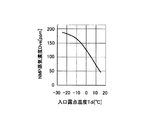
図2は、冷却器22の入口における排気ガスGの露点温度(以下、「入口露点温度Tdi」という)と、冷却器22の出口における排気ガスGに残存(残留)するNMP溶剤蒸気の濃度(以下、「NMP蒸気濃度」という)Dveとの関係を例示する図である。図2に示す入口露点温度TdiとNMP蒸気濃度Dveとの関係は、冷却器22の出口における排気ガスGの温度(以下、「出口ガス温度」という)Thgが12℃の場合のものを示したものである。排気ガスGにおける入口露点温度Tdiが高くなるに従い、排気ガスGに含まれるNMP溶剤蒸気及び水蒸気は冷却器22において凝縮しやすくなる。そのため、排気ガスGの入口露点温度TdiとNMP蒸気濃度Dveとの間には、入口露点温度Tdiが高いほどNMP蒸気濃度Dveが低くなるという関係が成り立つ。 FIG. 2 shows the dew point temperature of the exhaust gas G at the inlet of the cooler 22 (hereinafter referred to as “inlet dew point temperature Tdi”) and the concentration of NMP solvent vapor remaining (residual) in the exhaust gas G at the outlet of the cooler 22 ( FIG. 4 is a diagram illustrating the relationship with Dve (hereinafter referred to as “NMP vapor concentration”). The relationship between the inlet dew point temperature Tdi and the NMP vapor concentration Dve shown in FIG. 2 shows that the temperature of the exhaust gas G at the outlet of the cooler 22 (hereinafter referred to as “outlet gas temperature”) Thg is 12 ° C. Is. As the inlet dew point temperature Tdi in the exhaust gas G increases, the NMP solvent vapor and water vapor contained in the exhaust gas G tend to condense in the cooler 22. Therefore, a relationship is established between the inlet dew point temperature Tdi of the exhaust gas G and the NMP vapor concentration Dve that the higher the inlet dew point temperature Tdi, the lower the NMP vapor concentration Dve.
一方、図3は、入口露点温度Tdiと、冷却器22においてNMP溶剤蒸気が凝縮することで生成されるNMP凝縮液濃度Dlqとの関係を例示する図である。図3に示す入口露点温度TdiとNMP凝縮液濃度Dlqとの関係は、上述の出口ガス温度Thgが12℃の場合のものを示している。排気ガスGにおける入口露点温度Tdiが高くなるに従い、排気ガスG中の水蒸気の量が多くなるので、冷却器22において冷却された際にNMP溶剤蒸気とともに凝縮する水蒸気の凝縮量が増える。従って、排気ガスGにおける入口露点温度TdiとNMP凝縮液濃度Dlqとの間には、入口露点温度Tdiが高くなるに伴ってNMP凝縮液濃度Dlqが高くなるという関係が成り立つ。 On the other hand, FIG. 3 is a diagram illustrating the relationship between the inlet dew point temperature Tdi and the NMP condensate concentration Dlq generated when the NMP solvent vapor condenses in the cooler 22. The relationship between the inlet dew point temperature Tdi and the NMP condensate concentration Dlq shown in FIG. 3 indicates that when the outlet gas temperature Thg is 12 ° C. As the inlet dew point temperature Tdi in the exhaust gas G increases, the amount of water vapor in the exhaust gas G increases, so that the amount of water vapor condensed together with the NMP solvent vapor when cooled in the cooler 22 increases. Therefore, a relationship is established between the inlet dew point temperature Tdi and the NMP condensate concentration Dlq in the exhaust gas G, as the inlet dew point temperature Tdi increases.
冷却温度調整制御においては、冷却器22の出口におけるNMP蒸気濃度Dveと、NMP凝縮液濃度Dlqの双方が共に所定の適正範囲に収まるように、冷却器22における排気ガスGの冷却温度が制御される。 In the cooling temperature adjustment control, the cooling temperature of the exhaust gas G in the cooler 22 is controlled so that both the NMP vapor concentration Dve at the outlet of the cooler 22 and the NMP condensate concentration Dlq are both within a predetermined appropriate range. The
NMP蒸気濃度Dveの適正範囲は、排気ガスG’に残存するNMP溶剤蒸気を分離回収する吸着濃縮装置3の能力、すなわち吸着濃縮装置3において処理可能なNMP溶剤蒸気の濃度に応じて設定される。例えば、吸着濃縮装置3から処理済ガス路16へ送出される排気ガスG”に含まれるNMP溶剤蒸気に許容される濃度の上限値が20ppmであり、排気ガスG”に含まれるNMP溶剤蒸気の濃度を20ppm以下に維持するためには、吸着濃縮装置3に流入する排気ガスG’のNMP蒸気濃度を150ppm以下にする必要があると仮定する。この場合、冷却器22の出口におけるNMP蒸気濃度Dveに設定される許容上限濃度Dvsは、吸着濃縮装置3の処理能力を超えないように150ppm以下の濃度として設定される。本実施形態においては許容上限濃度Dvsが、第1の基準濃度に対応している。
The appropriate range of the NMP vapor concentration Dve is set according to the ability of the adsorption concentrator 3 to separate and recover the NMP solvent vapor remaining in the exhaust gas G ′, that is, the concentration of the NMP solvent vapor that can be processed in the adsorption concentrator 3. . For example, the upper limit value of the concentration allowed for the NMP solvent vapor contained in the exhaust gas G ″ sent from the adsorption concentrator 3 to the treated
次に、NMP凝縮液濃度Dlqの適正範囲について説明する。溶剤回収装置2における
NMP溶剤凝縮液の回収に際しては、NMP溶剤凝縮液に含まれる水の比率を低減し、回収するNMP溶剤凝縮液の濃度を比較的高く維持したいという基本的な要求がある。これは、回収容器65にて回収したNMP溶剤溶液を再利用に資することを考慮したものである。本実施形態に係る冷却温度調整制御では、NMP凝縮液濃度Dlqの下限側の閾値として設定される許容下限濃度Dlsbを80wt%に設定している。但し、この許容下限濃度Dlsbは、適宜変更してもよい。本実施形態においては許容下限濃度Dlsbが、第2の基準濃度に対応している。
Next, an appropriate range of the NMP condensate concentration Dlq will be described. When recovering the NMP solvent condensate in the
図4から6を参照して、冷却器22における排気ガスGの冷却温度の設定方法について説明する。図4は、冷却器22の出口における排気ガスGに含まれるNMP溶剤蒸気のNMP蒸気濃度Dveと出口ガス温度Thgとの関係を、入口ガス露点温度Tdi毎に例示した図である。図5は、冷却器22において生成されるNMP溶剤凝縮液のNMP凝縮液濃度Dlqと出口ガス温度Thgとの関係を、入口ガス露点温度Tdi毎に例示した図である。図4、5において、入口ガス露点温度Tdiは0℃、5℃、12℃の3水準を示している。また、出口ガス温度Thgは、冷却器22における冷却コイルの表面に排気ガスGが接触した際に冷却コイルの管内を流れる冷却水Nb(冷媒)との間で熱交換を行い、冷却された後の温度である。 A method for setting the cooling temperature of the exhaust gas G in the cooler 22 will be described with reference to FIGS. FIG. 4 is a diagram illustrating the relationship between the NMP vapor concentration Dve of the NMP solvent vapor contained in the exhaust gas G at the outlet of the cooler 22 and the outlet gas temperature Thg for each inlet gas dew point temperature Tdi. FIG. 5 is a diagram illustrating the relationship between the NMP condensate concentration Dlq of the NMP solvent condensate produced in the cooler 22 and the outlet gas temperature Thg for each inlet gas dew point temperature Tdi. 4 and 5, the inlet gas dew point temperature Tdi shows three levels of 0 ° C, 5 ° C, and 12 ° C. Further, the outlet gas temperature Thg is cooled by performing heat exchange with the cooling water Nb (refrigerant) flowing in the pipe of the cooling coil when the exhaust gas G contacts the surface of the cooling coil in the cooler 22. Temperature.
冷却器22において排気ガスGを冷却する際に、より低い温度に排気ガスGを冷却した方が(出口ガス温度Thgがより低くなるように排気ガスGを冷却した方が)、排気ガスGに含まれるNMP溶剤蒸気が凝縮しやすくなる。そのため、図4に示されるように、出口ガス温度Thgが低くなる程、冷却器2の出口において排気ガスGに残存するNMP溶剤蒸気のNMP蒸気濃度Dveは低くなる。ここで、NMP蒸気濃度Dveの許容上限濃度Dvsを150ppmに設定した場合、許容上限濃度Dvsに対応する出口ガス温度Thgは、入口ガス露点温度Tdiが0℃のケースで13℃、入口ガス露点温度Tdiが5℃のケースで15℃、入口ガス露点温度Tdiが12℃のケースで19℃である。例えば、排気ガスGのNMP蒸気濃度Dveを一定に制御する場合、入口ガス露点温度Tdiによって適正な出口ガス温度Thgが相違し、入口ガス露点温度Tdiが高いほど対応する出口ガス温度Thgが高くなることが、図4から読み取れる。これは、排気ガスGの入口ガス露点温度Tdiが高いほど、出口ガス温度Thgをあまり低温まで下げることなく、NMP蒸気濃度Dveを許容上限濃度Dvsである150ppm以下に維持することが可能であることを意味する。図4の例では、入口ガス露点温度Tdiが0℃のケースでは出口ガス温度Thgを13℃以下、入口ガス露点温度Tdiが5℃のケースでは出口ガス温度Thgを15℃以下、入口ガス露点温度Tdiが12℃のケースでは出口ガス温度Thgを19℃以下に調整することで、NMP蒸気濃度Dveを許容上限濃度Dvs(150ppm)以下の適正範囲に維持することができる。
When the exhaust gas G is cooled in the cooler 22, the exhaust gas G is cooled to a lower temperature (the exhaust gas G is cooled so that the outlet gas temperature Thg is lower). The contained NMP solvent vapor is likely to condense. Therefore, as shown in FIG. 4, the NMP vapor concentration Dve of the NMP solvent vapor remaining in the exhaust gas G at the outlet of the
次に、図5を参照して、NMP凝縮液濃度Dlqと出口ガス温度Thgとの関係を説明する。図5に示されるように、出口ガス温度Thgが高いときほど、NMP凝縮液濃度Dlqが高くなることが判る。更に、出口ガス温度Thgが等しい条件下では、排気ガスGにおける入口露点温度Tdiが低いほど、NMP凝縮液濃度Dlqが高くなる。入口露点温度TdiとNMP凝縮液濃度Dlqとの関係は、図3において説明したように、入口露点温度Tdiが高いほど、冷却器22において凝縮する水蒸気の凝縮量が増えることによるものである。 Next, the relationship between the NMP condensate concentration Dlq and the outlet gas temperature Thg will be described with reference to FIG. As shown in FIG. 5, it can be seen that the higher the outlet gas temperature Thg, the higher the NMP condensate concentration Dlq. Furthermore, under conditions where the outlet gas temperature Thg is equal, the NMP condensate concentration Dlq increases as the inlet dew point temperature Tdi in the exhaust gas G decreases. The relationship between the inlet dew point temperature Tdi and the NMP condensate concentration Dlq is due to an increase in the amount of water vapor condensed in the cooler 22 as the inlet dew point temperature Tdi is higher, as described with reference to FIG.
冷却温度調整制御においては、NMP凝縮液濃度Dlqを調整する際の下限値としての許容下限濃度Dlsbを80wt%に設定している。図5に示す例では、許容下限濃度Dlsb(80wt%)に対応する出口ガス温度Thgは、入口ガス露点温度Tdiが12℃のケースで17℃、入口ガス露点温度Tdiが5℃のケースで7℃である。また、入口ガス露点温度Tdiが0℃のケースで、出口ガス温度Thgは少なくとも5℃より低くな
っている。
In the cooling temperature adjustment control, the allowable lower limit concentration Dlsb as the lower limit value when adjusting the NMP condensate concentration Dlq is set to 80 wt%. In the example shown in FIG. 5, the outlet gas temperature Thg corresponding to the allowable lower limit concentration Dlsb (80 wt%) is 17 ° C. when the inlet gas dew point temperature Tdi is 12 ° C. and 7 when the inlet gas dew point temperature Tdi is 5 ° C. ° C. In the case where the inlet gas dew point temperature Tdi is 0 ° C., the outlet gas temperature Thg is at least lower than 5 ° C.
以上のことから、NMP凝縮液濃度Dlqを一定に制御しようとする場合、入口ガス露点温度Tdiによって適正な出口ガス温度Thgが相違し、入口ガス露点温度Tdiが高いほど対応する出口ガス温度Thgも高くなる。これは、排気ガスGの入口ガス露点温度Tdiが高い場合、出口ガス温度Thgcをあまり低温まで下げることなく、NMP凝縮液濃度Dlqを許容下限濃度Dlsbである80wt%以上に維持できることを意味する。図5の例では、入口ガス露点温度Tdiが12℃のケースでは出口ガス温度Thgを17℃以上、入口ガス露点温度Tdiが5℃のケースでは出口ガス温度Thgを7℃以上、入口ガス露点温度Tdiが0℃のケースでは出口ガス温度Thgを少なくとも5℃以上に調整することで、NMP凝縮液濃度Dlqを許容下限濃度Dlsb(80wt%)以上の適正範囲に維持できることが読み取れる。 From the above, when the NMP condensate concentration Dlq is to be controlled to be constant, the appropriate outlet gas temperature Thg differs depending on the inlet gas dew point temperature Tdi, and the higher the inlet gas dew point temperature Tdi, the corresponding outlet gas temperature Thg becomes. Get higher. This means that when the inlet gas dew point temperature Tdi of the exhaust gas G is high, the NMP condensate concentration Dlq can be maintained at 80 wt% or more, which is the allowable lower limit concentration Dlsb, without lowering the outlet gas temperature Thgc to a very low temperature. In the example of FIG. 5, when the inlet gas dew point temperature Tdi is 12 ° C., the outlet gas temperature Thg is 17 ° C. or higher, and when the inlet gas dew point temperature Tdi is 5 ° C., the outlet gas temperature Thg is 7 ° C. or higher. In the case where Tdi is 0 ° C., it can be read that the NMP condensate concentration Dlq can be maintained in an appropriate range above the allowable lower limit concentration Dlsb (80 wt%) by adjusting the outlet gas temperature Thg to at least 5 ° C. or more.
溶剤回収装置2の制御器24は、冷却器22の出口における排気ガスGのNMP蒸気濃度Dveが許容上限濃度Dvs以下に維持され、且つ、冷却器22で生成されるNMP溶剤凝縮液のNMP凝縮液濃度Dlqが許容下限濃度Dlsb以上に維持されるように定められる目標温度に、出口ガス温度Thgを制御する。本実施形態において、冷却温度調整制御を実行する制御器24が制御手段に対応する。
The
図4及び図5に示した例では、入口ガス露点温度Tdiが12℃の場合、出口ガス温度Thgの適正範囲は17〜19℃となる。また、入口ガス露点温度Tdiが5℃の場合、出口ガス温度Thgの適正範囲は7〜15℃となる。また、入口ガス露点温度Tdiが0℃の場合、出口ガス温度Thgの適正範囲は13℃以下となる。 In the example shown in FIGS. 4 and 5, when the inlet gas dew point temperature Tdi is 12 ° C., the appropriate range of the outlet gas temperature Thg is 17 to 19 ° C. When the inlet gas dew point temperature Tdi is 5 ° C., the appropriate range of the outlet gas temperature Thg is 7 to 15 ° C. When the inlet gas dew point temperature Tdi is 0 ° C., the appropriate range of the outlet gas temperature Thg is 13 ° C. or less.
図6は、冷却温度調整制御に係る入口ガス露点温度Tdiと出口ガス温度Thgの目標温度Ttgtとの関係を例示する図である。ここで、冷却器22を稼働させる際、目標温度Ttgtを低く設定する場合に比べて、高く設定する方が、冷凍機58の運転コスト、設備費用を抑えることができる。そこで、本実施形態においては、図6に示すように、冷却温度調整制御に係る出口ガス温度Thgの目標温度Ttgtを、入口ガス露点温度Tdiに応じて定まる適正範囲の上限値或いはその近傍の温度に設定するようにした。 FIG. 6 is a diagram illustrating the relationship between the inlet gas dew point temperature Tdi and the target temperature Ttgt of the outlet gas temperature Thg according to the cooling temperature adjustment control. Here, when the cooler 22 is operated, it is possible to reduce the operating cost and equipment cost of the refrigerator 58 when the target temperature Ttgt is set higher than when the target temperature Ttgt is set lower. Therefore, in the present embodiment, as shown in FIG. 6, the target temperature Ttgt of the outlet gas temperature Thg related to the cooling temperature adjustment control is set to the upper limit value of the appropriate range determined according to the inlet gas dew point temperature Tdi or a temperature in the vicinity thereof. Was set to.
なお、図6は、冷却器22の出口における排気ガスGのNMP蒸気濃度Dveを150ppmに制御する際の入口ガス露点温度Tdiと出口ガス温度Thgの目標温度Ttgtとの関係を示したものであり、NMP蒸気濃度Dveの値が変更されれば、入口ガス露点温度Tdiに対応する目標温度Ttgtの値が変化することは言うまでもない。また、図6に示した入口ガス露点温度Tdiと目標温度Ttgtとの関係は、上記(1)式で表すラウールの法則に基づいて求めることができる。 FIG. 6 shows the relationship between the inlet gas dew point temperature Tdi and the target temperature Ttgt of the outlet gas temperature Thg when the NMP vapor concentration Dve of the exhaust gas G at the outlet of the cooler 22 is controlled to 150 ppm. Needless to say, if the value of the NMP vapor concentration Dve is changed, the value of the target temperature Ttgt corresponding to the inlet gas dew point temperature Tdi changes. Further, the relationship between the inlet gas dew point temperature Tdi and the target temperature Ttgt shown in FIG. 6 can be obtained based on Raoul's law expressed by the above equation (1).
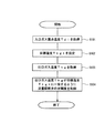
図7は、冷却温度調整制御に係る処理フローを示すフローチャートである。図7に示すフローチャートは、制御器24のプロセッサがメモリに記憶されている制御プログラムを実行することにより実現される。この制御プログラムは、例えば溶剤回収装置2の稼働中において、所定周期毎に繰り返し実行されるようになっている。
FIG. 7 is a flowchart showing a processing flow relating to the cooling temperature adjustment control. The flowchart shown in FIG. 7 is realized by the processor of the
ステップS101において、制御器24は、露点温度計61が出力する信号に基づいて、冷却器22の入口における排気ガスGの露点温度である入口ガス露点温度Tdiを取得する。ステップS102において、制御器24は、メモリに格納されている図6に示したマップ、すなわち出口ガス温度Thgの目標温度Ttgtと入口ガス露点温度Tdiとの関係を規定されたマップを参照する。そして、このマップに現在のガス露点温度Tdiを入力して、対応する目標温度Ttgtを読み出す。
In step S <b> 101, the
続くステップS103において、制御器24は、温度計62が出力する信号に基づいて、現在の出口ガス温度Thgを取得する。そして、制御器24は、ステップS104に進み、出口ガス温度Thgが目標温度Ttgtに一致するように流量調節弁60の弁開度を制御する。その結果、冷却器22の冷却コイルに対して冷凍機58から供給される冷却水Nbの流量が調節され、出口ガス温度Thgが設定目標温度Ttgtに一致するように制御される。
In subsequent step S103, the
ステップS104では、出口ガス温度Thgと設定目標温度Ttgtとの差が基準値以下となるまで、流量調節弁60の弁開度をフィードバック制御してもよいし、また、出口ガス温度Thgと設定目標温度Ttgtとの差に応じて流量調節弁60の弁開度をフィードフォワード制御してもよい。勿論、制御器24は、冷却水Nbの流量を調節する代わりに、或いは冷却水Nbの流量調節と併行して、冷凍機58から送り出される冷却水Nbの温度を、例えばインバータ制御などによって調節してもよい。ステップS104の処理が終了すると、制御器24は本処理フローを一旦終了させる。制御器24は、所定の周期毎に本処理フローを繰り返し実行することで、冷却器22に導入される排気ガスGの入口ガス露点温度Tdiに応じて、冷却器22の出口における排気ガスGの温度である出口ガス温度Thgが調節される。
In step S104, the valve opening degree of the flow
以上のように、本実施形態に係る冷却温度調整制御によれば、ラウールの法則に基づいて、NMP蒸気濃度Dveが許容上限濃度Dvs以下となるとともにNMP凝縮液濃度Dlqが許容下限濃度Dlsb以上となるような出口ガス温度Thg(目標温度Ttgt)と入口ガス露点温度Tdiとの関係を予め把握しておき、これらの関係が規定された図6に示すマップを制御器24のメモリに記憶しておく。そして、逐次、入口ガス露点温度Tdiを取得する毎に図6に示すマップにアクセスし、入口ガス露点温度Tdiに対応する出口ガス温度Thgを読み出すとともに、その読み出した値を出口ガス温度Thgの目標温度Ttgtに設定する。
As described above, according to the cooling temperature adjustment control according to the present embodiment, based on Raoul's law, the NMP vapor concentration Dve is equal to or lower than the allowable upper limit concentration Dvs and the NMP condensate concentration Dlq is equal to or higher than the allowable lower limit concentration Dlsb. The relationship between the outlet gas temperature Thg (target temperature Ttgt) and the inlet gas dew point temperature Tdi is grasped in advance, and the map shown in FIG. 6 in which these relationships are defined is stored in the memory of the
これによれば、冷却器22の出口における排気ガスGに残存するNMP溶剤蒸気のNMP蒸気濃度Dveを、予め設定された許容レベル(例えば、150ppm以下)に抑えることができ、且つ、冷却器22において生成されるNMP溶剤凝縮液の濃度を比較的高いレベル(例えば、80wt%以上)に維持することができる。 According to this, the NMP vapor concentration Dve of the NMP solvent vapor remaining in the exhaust gas G at the outlet of the cooler 22 can be suppressed to a preset allowable level (for example, 150 ppm or less), and the cooler 22 Can maintain the concentration of the NMP solvent condensate produced at a relatively high level (for example, 80 wt% or more).
更に、本実施形態に係る冷却温度調整制御によれば、冷却器22に流入する排気ガスGの入口ガス露点温度Tdiが変動しても、その入口ガス露点温度Tdiに応じて出口ガス温度Thgを適切な温度に調整することができる。これによれば、入口ガス露点温度Tdiが比較的に高いときには、出口ガス温度Thgの目標温度Ttgtを比較的高めに設定することができるため、冷凍機58の運転コストを低減することができる。 Furthermore, according to the cooling temperature adjustment control according to the present embodiment, even if the inlet gas dew point temperature Tdi of the exhaust gas G flowing into the cooler 22 fluctuates, the outlet gas temperature Thg is set according to the inlet gas dew point temperature Tdi. It can be adjusted to an appropriate temperature. According to this, when the inlet gas dew point temperature Tdi is relatively high, the target temperature Ttgt of the outlet gas temperature Thg can be set relatively high, so that the operating cost of the refrigerator 58 can be reduced.
以上より、本実施形態に係る溶剤回収装置2は、冷却器22に流入する排気ガスGの湿度(露点温度)に応じて、NMP蒸気濃度Dve及びNMP凝縮液濃度Dlqを所望のレベルに管理することができ、しかも、排気ガスGの冷却時に消費されるエネルギー量を可及的に低減することができるので冷凍機58の運転コスト削減の観点からも有利である。
As described above, the
次に、実施形態に係る溶剤回収システム1の変形例について説明する。ここで、濃度が85wt%を超えるNMP溶剤は危険物の扱いになるため、回収したNMP溶剤凝縮液が過度に高くならないようにしたいという要請がある。そこで、第1変形例においては、回収容器65に貯留されているNMP溶剤凝縮液の濃度が85wt%を超えた場合には、回収容器65に水を添加する等してNMP溶剤凝縮液の濃度を85wt%以下に維持するとよい。例えば、回収容器65に貯留されているNMP溶剤凝縮液の濃度を80〜85wt%の範囲に維持されるように、必要に応じてNMP溶剤凝縮液に水を添加することが好ま
しい。
Next, a modified example of the
次に、溶剤回収システム1における第2変形例について説明する。本変形例では、排気ガスGにおける入口露点温度Tdiが基準露点温度Tdib以下に維持されるように、外調機6を用いて予め外気OA(給気A)を除湿する。
Next, a second modification of the
ところで、排気ガスGの入口露点温度Tdiが高くなるに従い、冷却器22の出口におけるNMP蒸気濃度Dveを許容上限濃度Dvs以下に維持する事が可能な出口ガス温度Thgの上限値と、NMP凝縮液濃度Dlqを許容下限濃度Dlsb以上に維持可能な出口ガス温度Thgの下限値の双方が上昇する(図4、5を参照)。 By the way, as the inlet dew point temperature Tdi of the exhaust gas G increases, the upper limit value of the outlet gas temperature Thg at which the NMP vapor concentration Dve at the outlet of the cooler 22 can be maintained below the allowable upper limit concentration Dvs, and the NMP condensate Both lower limit values of the outlet gas temperature Thg that can maintain the concentration Dlq above the allowable lower limit concentration Dlsb rise (see FIGS. 4 and 5).
従って、入口露点温度Tdiが高くなり過ぎると、NMP蒸気濃度Dve及びNMP凝縮液濃度Dlqを同時に適正範囲に維持できる温度に出口ガス温度Thgの目標温度Ttgtを設定することができなくなる虞がある。例えば、東京の夏期における設計外気温湿度条件である、気温33℃、相対湿度60%RHであれば、外気OAの露点温度は24℃となる。この条件下では、冷却器22に乾燥炉4から排出された排気ガスGをそのまま導いたのでは、入口露点温度Tdiが高すぎてしまい、出口ガス温度Thgの目標温度Ttgtを適切に設定することができなくなる。 Therefore, if the inlet dew point temperature Tdi becomes too high, the target temperature Ttgt of the outlet gas temperature Thg may not be set to a temperature at which the NMP vapor concentration Dve and the NMP condensate concentration Dlq can be simultaneously maintained in appropriate ranges. For example, the dew point temperature of the outside air OA is 24 ° C. if the design outside air temperature and humidity conditions in summer in Tokyo are an air temperature of 33 ° C. and a relative humidity of 60% RH. Under this condition, if the exhaust gas G discharged from the drying furnace 4 is introduced to the cooler 22 as it is, the inlet dew point temperature Tdi is too high, and the target temperature Ttgt of the outlet gas temperature Thg is set appropriately. Can not be.
そこで、本変形例において、外調機6は、冷却器22の出口におけるNMP溶剤蒸気のNMP蒸気濃度Dveが許容上限濃度Dvs以下となる第1の条件と、冷却器22において生成されるNMP溶剤凝縮液のNMP凝縮液濃度Dlqが許容下限濃度Dlsb以上となる第2の条件の双方を満足する出口ガス温度Thgの目標温度Ttgtが定まるように、外気OAを除湿するようにした。
Therefore, in this modification, the
本変形例において、上記基準露点温度Tdibは12℃に設定されており、入口露点温度Tdiが12℃以下となるように、外気OAは必要に応じて外調機6によって除湿される。例えば、外調機6は、入口露点温度Tdiが12℃以下に保たれるように、温度23℃、相対湿度50%RH程度の空調条件にて外気OAを除湿し、外気OAの露点温度を予め低下させておくようにしてもよい。
In this modification, the reference dew point temperature Tdib is set to 12 ° C., and the outside air OA is dehumidified by the
これによれば、外部から取り込まれる外気OAの露点温度が高くなる条件下であっても、外調機6が外気OAの除湿を行う事によって、上述した第1の条件と第2の条件の双方を満足するような目標温度Ttgtを容易に設定することができる。なお、第1の条件に関し、許容上限濃度Dvsは、吸着濃縮装置3の処理能力(容量)に応じて決定される。そのため、基準露点温度Tdibの設定は、吸着濃縮装置3の処理能力(容量)の大小を考慮して定めることが好ましい。別の言い方をすると、吸着濃縮装置3の容量は、外調機6や冷却器22の処理能力を考慮して決定することが好ましい。
According to this, even under the condition that the dew point temperature of the outside air OA taken from outside becomes high, the
なお、本変形例においては、排ガス路66に空調機(図示せず)を配置し、この空調機を用いて乾燥炉4から排出された後であって冷却器22に導入される前の排気ガスGを除湿してもよい。この場合、排ガス路66に配置する空調機及び外調機6を併用して、入口露点温度Tdiを基準露点温度Tdib以下にコントロールしてもよい。
In this modification, an air conditioner (not shown) is disposed in the
以上述べた実施の形態は本発明を説明するための一例であって、本発明の本旨を逸脱しない範囲内において種々の変更を加え得る。上述した実施形態及びその変形例は、組み合わせて実施することができる。 The embodiment described above is an example for explaining the present invention, and various modifications can be made without departing from the spirit of the present invention. The above-described embodiment and its modifications can be implemented in combination.
1・・・溶剤回収システム
2・・・溶剤回収装置
3・・・吸着濃縮装置
4・・・乾燥炉
21・・熱回収器
22・・冷却器
23・・再熱器
24・・制御器
DESCRIPTION OF
Claims (2)
冷却媒体が管内を流れる冷却コイルに前記被処理ガスを接触させて、該被処理ガスに含まれる溶剤蒸気を凝縮させる冷却器と、
前記冷却器に導入される被処理ガスの露点温度に応じて、前記冷却器の出口における被処理ガスの温度である出口ガス温度を目標温度に調整する制御手段と、
溶剤蒸気が発生すると共に該溶剤蒸気を含む被処理ガスが排出される処理室に供給される前の給気を除湿して露点温度を低下させる除湿手段と、
を備え、
前記制御手段は、前記冷却器の出口における被処理ガスに残存する溶剤蒸気の濃度が前記溶剤回収装置の後段に設けられる吸着濃縮装置の処理能力に応じて設定される第1の基準濃度以下であって、かつ、前記冷却器において生成される溶剤凝縮液の濃度が第2の基準濃度以上となるような、前記被処理ガスの露点温度と前記第1の基準濃度とに応じて上限値が定まると共に前記被処理ガスの露点温度と前記第2の基準濃度とに応じて下限値が定まる、前記出口ガス温度の適性範囲の上限値或いは当該上限値近傍の温度であって且つ前記被処理ガスの露点温度が高いほど高い温度として、前記出口ガス温度の目標温度を設定し、
前記除湿手段は、前記冷却器の出口における被処理ガスに残存する溶剤蒸気の濃度が第1の基準濃度以下となる第1の条件と、前記冷却器において生成される溶剤凝縮液の濃度が第2の基準濃度以上となる第2の条件の双方を満足する前記出口ガス温度の目標温度が定まるように、前記処理室に供給される前の給気を除湿する、
溶剤回収装置。 A solvent recovery device for recovering a solvent from a gas to be treated containing solvent vapor,
A cooler in which the gas to be treated is brought into contact with a cooling coil in which a cooling medium flows in the pipe, and the solvent vapor contained in the gas to be treated is condensed;
Control means for adjusting the outlet gas temperature, which is the temperature of the gas to be treated at the outlet of the cooler, to a target temperature according to the dew point temperature of the gas to be treated introduced into the cooler;
Dehumidifying means for dehumidifying the supply air before being supplied to the processing chamber in which solvent vapor is generated and the gas to be processed containing the solvent vapor is discharged, and for reducing the dew point temperature;
With
The control means is configured such that the concentration of the solvent vapor remaining in the gas to be processed at the outlet of the cooler is equal to or lower than a first reference concentration set according to the processing capacity of the adsorption concentrating device provided at the subsequent stage of the solvent recovery device. And an upper limit is set according to the dew point temperature of the gas to be treated and the first reference concentration such that the concentration of the solvent condensate produced in the cooler is equal to or higher than the second reference concentration. The lower limit value is determined according to the dew point temperature of the gas to be processed and the second reference concentration, and is the upper limit value of the appropriate range of the outlet gas temperature or a temperature in the vicinity of the upper limit value , and the gas to be processed The higher the dew point temperature, the higher the outlet gas temperature target temperature ,
The dehumidifying means has a first condition in which the concentration of solvent vapor remaining in the gas to be treated at the outlet of the cooler is equal to or lower than a first reference concentration, and the concentration of solvent condensate generated in the cooler is first. Dehumidifying the supply air before being supplied to the processing chamber so that the target temperature of the outlet gas temperature satisfying both of the second conditions that are equal to or higher than the reference concentration of 2 is determined.
Solvent recovery device.
前記冷却器に導入される被処理ガスの露点温度に応じて、前記冷却器の出口における被処理ガスの温度である出口ガス温度を目標温度に調整する冷却温度調整ステップを有し、
前記出口ガス温度の目標温度は、前記冷却器の出口における被処理ガスに残存する溶剤蒸気の濃度が前記溶剤回収装置の後段に設けられる吸着濃縮装置の処理能力に応じて設定される吸着濃縮装置の処理能力に応じて設定される第1の基準濃度以下であって、かつ、
前記冷却器において生成される溶剤凝縮液の濃度が第2の基準濃度以上となるような、前記被処理ガスの露点温度と前記第1の基準濃度とに応じて上限値が定まると共に前記被処理ガスの露点温度と前記第2の基準濃度とに応じて下限値が定まる、前記出口ガス温度の適性範囲の上限値或いは当該上限値近傍の温度であって且つ前記被処理ガスの露点温度が高いほど高い温度として設定され、
前記冷却器の出口における被処理ガスに残存する溶剤蒸気の濃度が第1の基準濃度以下となる第1の条件と、前記冷却器において生成される溶剤凝縮液の濃度が第2の基準濃度以上となる第2の条件の双方を満足する前記出口ガス温度の目標温度が定まるように、溶剤蒸気が発生すると共に該溶剤蒸気を含む被処理ガスが排出される処理室に供給される前の給気を除湿するステップを更に有する、
溶剤回収装置の制御方法。 A method for controlling a solvent recovery apparatus comprising a cooler that causes a gas to be treated to contact a cooling coil in which a cooling medium flows in a pipe and condenses solvent vapor contained in the gas to be treated,
A cooling temperature adjusting step of adjusting an outlet gas temperature, which is a temperature of the gas to be processed at an outlet of the cooler, to a target temperature according to a dew point temperature of the gas to be processed introduced into the cooler;
The target temperature of the outlet gas temperature is an adsorption concentration apparatus in which the concentration of the solvent vapor remaining in the gas to be processed at the outlet of the cooler is set according to the processing capacity of the adsorption concentration apparatus provided at the subsequent stage of the solvent recovery apparatus Less than or equal to the first reference concentration set according to the processing capacity of
The upper limit value is determined according to the dew point temperature of the gas to be processed and the first reference concentration so that the concentration of the solvent condensate generated in the cooler is equal to or higher than the second reference concentration, and the object to be processed. The lower limit value is determined according to the dew point temperature of the gas and the second reference concentration. The upper limit value of the suitable range of the outlet gas temperature or a temperature in the vicinity of the upper limit value , and the dew point temperature of the gas to be treated is high. Set as high temperature ,
The first condition that the concentration of the solvent vapor remaining in the gas to be treated at the outlet of the cooler is equal to or lower than the first reference concentration, and the concentration of the solvent condensate generated in the cooler is equal to or higher than the second reference concentration In order to determine a target temperature of the outlet gas temperature that satisfies both of the second conditions to be satisfied, supply of the solvent vapor is generated and the supply gas before being supplied to the processing chamber in which the gas to be processed containing the solvent vapor is exhausted. Further comprising the step of dehumidifying,
Control method of solvent recovery device.
Priority Applications (1)
| Application Number | Priority Date | Filing Date | Title |
|---|---|---|---|
| JP2012137751A JP6078237B2 (en) | 2012-06-19 | 2012-06-19 | Solvent recovery apparatus and control method thereof |
Applications Claiming Priority (1)
| Application Number | Priority Date | Filing Date | Title |
|---|---|---|---|
| JP2012137751A JP6078237B2 (en) | 2012-06-19 | 2012-06-19 | Solvent recovery apparatus and control method thereof |
Publications (2)
| Publication Number | Publication Date |
|---|---|
| JP2014000526A JP2014000526A (en) | 2014-01-09 |
| JP6078237B2 true JP6078237B2 (en) | 2017-02-08 |
Family
ID=50034228
Family Applications (1)
| Application Number | Title | Priority Date | Filing Date |
|---|---|---|---|
| JP2012137751A Active JP6078237B2 (en) | 2012-06-19 | 2012-06-19 | Solvent recovery apparatus and control method thereof |
Country Status (1)
| Country | Link |
|---|---|
| JP (1) | JP6078237B2 (en) |
Families Citing this family (6)
| Publication number | Priority date | Publication date | Assignee | Title |
|---|---|---|---|---|
| JP6458465B2 (en) * | 2014-11-28 | 2019-01-30 | 東洋紡株式会社 | Organic solvent recovery system |
| CN108404604B (en) * | 2018-03-23 | 2023-11-28 | 中创新航技术研究院(江苏)有限公司 | Circulating type low dew point NMP (N-methyl pyrrolidone) recovery system and operation method thereof |
| US11130091B2 (en) * | 2019-07-11 | 2021-09-28 | Durr Systems, Inc. | Apparatus and method for solvent recovery from drying process |
| US12102955B2 (en) | 2019-07-11 | 2024-10-01 | Durr Systems, Inc. | Apparatus and method for solvent recovery from drying process |
| KR102115135B1 (en) * | 2020-04-07 | 2020-06-05 | 조상용 | rapid cooling unit |
| CN114254714B (en) * | 2022-02-28 | 2022-04-29 | 东莞市鹏锦机械科技有限公司 | Efficient NMP recovery method, system and computer-readable storage medium |
Family Cites Families (3)
| Publication number | Priority date | Publication date | Assignee | Title |
|---|---|---|---|---|
| JP2006281045A (en) * | 2005-03-31 | 2006-10-19 | Matsushita Electric Ind Co Ltd | Gas recovery apparatus |
| JP5243900B2 (en) * | 2008-09-19 | 2013-07-24 | 株式会社大気社 | Solvent recovery equipment |
| CN102335521B (en) * | 2010-07-16 | 2015-05-20 | 杰智环境科技股份有限公司 | Device and method for recycling and purifying organic solvent by temperature reduction and nucleation |
-
2012
- 2012-06-19 JP JP2012137751A patent/JP6078237B2/en active Active
Also Published As
| Publication number | Publication date |
|---|---|
| JP2014000526A (en) | 2014-01-09 |
Similar Documents
| Publication | Publication Date | Title |
|---|---|---|
| JP5243900B2 (en) | Solvent recovery equipment | |
| JP6078237B2 (en) | Solvent recovery apparatus and control method thereof | |
| JP6665063B2 (en) | Drying equipment | |
| CN107138023B (en) | Absorption type removing/concentrating device | |
| KR101565033B1 (en) | NMP recovery purification system | |
| JP5588163B2 (en) | Solvent recovery device | |
| JP4423499B2 (en) | Absorption type dehumidification air conditioning system | |
| EP2883595A1 (en) | Exhaust gas treatment system | |
| WO2020102467A1 (en) | Exhaust gas purification system and method and data processing system for monitoring at least one exhaust gas purification system | |
| JP2013111543A (en) | Solvent recovery system | |
| JP6024982B2 (en) | Solvent recovery equipment | |
| JP2005233435A5 (en) | ||
| GB2552239A (en) | Heat pumps utilizing Ionic liquid desiccant | |
| JP5351109B2 (en) | Solvent recovery device | |
| KR101723507B1 (en) | System for separating chemical material from exhaust gas | |
| JP6458465B2 (en) | Organic solvent recovery system | |
| CN109922893A (en) | Coating drying equipment | |
| JP2012011343A (en) | Apparatus for generating low dew point air | |
| JP2009066578A (en) | Organic solvent gas treatment device | |
| JP5628051B2 (en) | Solvent recovery system | |
| JP2012115773A (en) | Adsorption/desorption type concentrator | |
| JP2013132582A (en) | Organic solvent-containing gas treatment system | |
| JP2008100187A (en) | System for treatment of gas containing organic solvent | |
| JP2012130875A (en) | Solvent recovery apparatus | |
| JP5600048B2 (en) | Solvent recovery device |
Legal Events
| Date | Code | Title | Description |
|---|---|---|---|
| A621 | Written request for application examination |
Free format text: JAPANESE INTERMEDIATE CODE: A621 Effective date: 20150511 |
|
| A977 | Report on retrieval |
Free format text: JAPANESE INTERMEDIATE CODE: A971007 Effective date: 20160426 |
|
| A131 | Notification of reasons for refusal |
Free format text: JAPANESE INTERMEDIATE CODE: A131 Effective date: 20160524 |
|
| A521 | Written amendment |
Free format text: JAPANESE INTERMEDIATE CODE: A523 Effective date: 20160725 |
|
| A02 | Decision of refusal |
Free format text: JAPANESE INTERMEDIATE CODE: A02 Effective date: 20160830 |
|
| A521 | Written amendment |
Free format text: JAPANESE INTERMEDIATE CODE: A523 Effective date: 20161130 |
|
| A911 | Transfer to examiner for re-examination before appeal (zenchi) |
Free format text: JAPANESE INTERMEDIATE CODE: A911 Effective date: 20161207 |
|
| TRDD | Decision of grant or rejection written | ||
| A01 | Written decision to grant a patent or to grant a registration (utility model) |
Free format text: JAPANESE INTERMEDIATE CODE: A01 Effective date: 20170110 |
|
| A61 | First payment of annual fees (during grant procedure) |
Free format text: JAPANESE INTERMEDIATE CODE: A61 Effective date: 20170116 |
|
| R150 | Certificate of patent or registration of utility model |
Ref document number: 6078237 Country of ref document: JP Free format text: JAPANESE INTERMEDIATE CODE: R150 |