EP4079582B1 - Seitenairbaganordnungen und montageverfahren - Google Patents
Seitenairbaganordnungen und montageverfahren Download PDFInfo
- Publication number
- EP4079582B1 EP4079582B1 EP22166270.3A EP22166270A EP4079582B1 EP 4079582 B1 EP4079582 B1 EP 4079582B1 EP 22166270 A EP22166270 A EP 22166270A EP 4079582 B1 EP4079582 B1 EP 4079582B1
- Authority
- EP
- European Patent Office
- Prior art keywords
- cap
- inflator
- airbag assembly
- panel
- inflatable
- Prior art date
- Legal status (The legal status is an assumption and is not a legal conclusion. Google has not performed a legal analysis and makes no representation as to the accuracy of the status listed.)
- Active
Links
Images


Classifications
-
- B—PERFORMING OPERATIONS; TRANSPORTING
- B60—VEHICLES IN GENERAL
- B60R—VEHICLES, VEHICLE FITTINGS, OR VEHICLE PARTS, NOT OTHERWISE PROVIDED FOR
- B60R21/00—Arrangements or fittings on vehicles for protecting or preventing injuries to occupants or pedestrians in case of accidents or other traffic risks
- B60R21/02—Occupant safety arrangements or fittings, e.g. crash pads
- B60R21/16—Inflatable occupant restraints or confinements designed to inflate upon impact or impending impact, e.g. air bags
- B60R21/20—Arrangements for storing inflatable members in their non-use or deflated condition; Arrangement or mounting of air bag modules or components
- B60R21/207—Arrangements for storing inflatable members in their non-use or deflated condition; Arrangement or mounting of air bag modules or components in vehicle seats
-
- B—PERFORMING OPERATIONS; TRANSPORTING
- B60—VEHICLES IN GENERAL
- B60R—VEHICLES, VEHICLE FITTINGS, OR VEHICLE PARTS, NOT OTHERWISE PROVIDED FOR
- B60R21/00—Arrangements or fittings on vehicles for protecting or preventing injuries to occupants or pedestrians in case of accidents or other traffic risks
- B60R21/02—Occupant safety arrangements or fittings, e.g. crash pads
- B60R21/16—Inflatable occupant restraints or confinements designed to inflate upon impact or impending impact, e.g. air bags
- B60R21/20—Arrangements for storing inflatable members in their non-use or deflated condition; Arrangement or mounting of air bag modules or components
- B60R21/201—Packaging straps or envelopes for inflatable members
-
- B—PERFORMING OPERATIONS; TRANSPORTING
- B60—VEHICLES IN GENERAL
- B60R—VEHICLES, VEHICLE FITTINGS, OR VEHICLE PARTS, NOT OTHERWISE PROVIDED FOR
- B60R21/00—Arrangements or fittings on vehicles for protecting or preventing injuries to occupants or pedestrians in case of accidents or other traffic risks
- B60R21/02—Occupant safety arrangements or fittings, e.g. crash pads
- B60R21/16—Inflatable occupant restraints or confinements designed to inflate upon impact or impending impact, e.g. air bags
- B60R21/20—Arrangements for storing inflatable members in their non-use or deflated condition; Arrangement or mounting of air bag modules or components
- B60R21/215—Arrangements for storing inflatable members in their non-use or deflated condition; Arrangement or mounting of air bag modules or components characterised by the covers for the inflatable member
-
- B—PERFORMING OPERATIONS; TRANSPORTING
- B60—VEHICLES IN GENERAL
- B60R—VEHICLES, VEHICLE FITTINGS, OR VEHICLE PARTS, NOT OTHERWISE PROVIDED FOR
- B60R21/00—Arrangements or fittings on vehicles for protecting or preventing injuries to occupants or pedestrians in case of accidents or other traffic risks
- B60R21/02—Occupant safety arrangements or fittings, e.g. crash pads
- B60R21/16—Inflatable occupant restraints or confinements designed to inflate upon impact or impending impact, e.g. air bags
- B60R21/20—Arrangements for storing inflatable members in their non-use or deflated condition; Arrangement or mounting of air bag modules or components
- B60R21/217—Inflation fluid source retainers, e.g. reaction canisters; Connection of bags, covers, diffusers or inflation fluid sources therewith or together
- B60R21/2176—Inflation fluid source retainers, e.g. reaction canisters; Connection of bags, covers, diffusers or inflation fluid sources therewith or together the air bag components being completely enclosed in a soft or semi-rigid housing or cover
-
- B—PERFORMING OPERATIONS; TRANSPORTING
- B60—VEHICLES IN GENERAL
- B60R—VEHICLES, VEHICLE FITTINGS, OR VEHICLE PARTS, NOT OTHERWISE PROVIDED FOR
- B60R21/00—Arrangements or fittings on vehicles for protecting or preventing injuries to occupants or pedestrians in case of accidents or other traffic risks
- B60R21/02—Occupant safety arrangements or fittings, e.g. crash pads
- B60R21/16—Inflatable occupant restraints or confinements designed to inflate upon impact or impending impact, e.g. air bags
- B60R21/23—Inflatable members
- B60R21/231—Inflatable members characterised by their shape, construction or spatial configuration
- B60R21/23138—Inflatable members characterised by their shape, construction or spatial configuration specially adapted for side protection
-
- B—PERFORMING OPERATIONS; TRANSPORTING
- B60—VEHICLES IN GENERAL
- B60R—VEHICLES, VEHICLE FITTINGS, OR VEHICLE PARTS, NOT OTHERWISE PROVIDED FOR
- B60R21/00—Arrangements or fittings on vehicles for protecting or preventing injuries to occupants or pedestrians in case of accidents or other traffic risks
- B60R21/02—Occupant safety arrangements or fittings, e.g. crash pads
- B60R21/16—Inflatable occupant restraints or confinements designed to inflate upon impact or impending impact, e.g. air bags
- B60R21/23—Inflatable members
- B60R21/237—Inflatable members characterised by the way they are folded
-
- B—PERFORMING OPERATIONS; TRANSPORTING
- B60—VEHICLES IN GENERAL
- B60R—VEHICLES, VEHICLE FITTINGS, OR VEHICLE PARTS, NOT OTHERWISE PROVIDED FOR
- B60R21/00—Arrangements or fittings on vehicles for protecting or preventing injuries to occupants or pedestrians in case of accidents or other traffic risks
- B60R21/02—Occupant safety arrangements or fittings, e.g. crash pads
- B60R21/16—Inflatable occupant restraints or confinements designed to inflate upon impact or impending impact, e.g. air bags
- B60R21/23—Inflatable members
- B60R21/231—Inflatable members characterised by their shape, construction or spatial configuration
- B60R21/23138—Inflatable members characterised by their shape, construction or spatial configuration specially adapted for side protection
- B60R2021/23146—Inflatable members characterised by their shape, construction or spatial configuration specially adapted for side protection seat mounted
Definitions
- the present disclosure relates generally to the field of automotive protective systems. More specifically, the present disclosure relates to side airbag systems that are configured to deploy in response to collision events.
- DE102006031117A1 and JP2015074295A disclose examples of arrangements of side airbag systems that are configured to deploy in response to collision events.
- An airbag assembly according to an aspect of the present invention is set forth in claim 1.
- a method of packaging a side airbag assembly according to a second aspect of the invention is set forth in claim 14.
- Inflatable airbag assemblies are widely used to reduce or minimize occupant injury during a collision event.
- Airbag modules have been installed at various locations within a vehicle, including, but not limited to, in the steering wheel, in the dashboard and/or instrument panel, within the side doors or side seats, adjacent to a roof rail of the vehicle, in an overhead position, or at the knee or leg position.
- the disclosed airbag assemblies and airbag embodiments may be utilized in place of or in conjunction with other airbags, such as, for example, a front passenger airbag that is typically housed within the dashboard, driver airbags housed within the steering wheel, knee airbags, and side airbags.
- the disclosed airbag assemblies may be used in an autonomous vehicle (e.g., in a vehicle that may not have a steering wheel and/or that may have limited, or no, reaction surface such as an instrument panel).
- the terms “dashboard” and “instrument panel” refer to a protruding region of a vehicle faced by a motor vehicle occupant, which often includes a glove compartment in a portion thereof that faces a passenger and may include instruments (e.g., radio and/or climate controls) in a more central region thereof, although such instruments need not be present.
- instruments e.g., radio and/or climate controls
- opposite is a relational term used herein to refer to a placement of a particular feature or component in a position corresponding to another related feature or component wherein the corresponding features or components are positionally juxtaposed to each other.
- a person's right hand is opposite the person's left hand.
- An inboard component may be situated opposite an outboard component.
- Coupled to and “in communication with” refer to any form of interaction between two or more entities, including mechanical, electrical, magnetic, electromagnetic, fluid, and thermal interaction. Two components may be coupled to each other even though they are not in direct contact with each other.
- inboard refers to a direction toward a centerline of a vehicle
- outboard refers to a direction out of the vehicle and away from a centerline of the vehicle.
- ride down as used in this disclosure bears the ordinary meaning of the words relative to inflatable airbag systems. That is, “ride down” typically involves an occupant in contact with an inflatable airbag cushion for some period of time during which the inflatable airbag cushion may support and nominally protect to some degree the occupant from impact(s) with some structure(s)/component(s) of a vehicle, and during which the inflatable airbag cushion may partially deflate to ameliorate deceleration forces.
- fluid communication is used in its ordinary sense, and is broad enough to refer to arrangements in which a fluid (e.g., a gas or a liquid) can flow from one element to another element when the elements are in fluid communication with each other.
- a fluid e.g., a gas or a liquid
- longitudinal and longitudinal refer to a direction or orientation extending or spanning between a front of a vehicle and a rear of the vehicle.
- the disclosed airbags are typically in a packaged state (e.g., are rolled, folded, and/or otherwise compressed) or a compact configuration and may be retained in the packaged state by a wrapper.
- an inflator is triggered, which rapidly fills the airbag with inflation gas.
- the airbag can rapidly transition from a packaged state (e.g., a compact configuration) to a deployed state or an expanded configuration.
- the expanding airbag can tear open the wrapper.
- the inflator may be triggered by any suitable device or system, and the triggering may be in response to and/or influenced by one or more vehicle sensors.
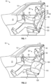
- FIG. 1 is a side view of an interior of a vehicle 10 having a side airbag assembly 100 in a packaged and undeployed state.
- a dashboard (or instrument panel) 11, windscreen 12, roof 14, and door 20 are shown for reference.
- a vehicle seating position 30 is also shown.
- An occupant 50 is shown in the vehicle seating position 30 in a seated and upright position.
- the vehicle seating position 30 shown is a front driver location; however, embodiments of the disclosure herein may be suitable for other vehicle seating positions 30 within the vehicle 10, such as a front passenger seat, and the like.
- the vehicle seating position 30 can include an occupant seat 32, a seat back 34, and a restraint harness 40.
- the side airbag assembly 100 is mounted at an outboard portion of the seat back 34 (proximal to the viewing plane of FIG. 1 ).
- the side airbag assembly 100 may couple at the seat back 34 such that the side airbag assembly 100 may be substantially within the seat back 34 and at a position lateral to the vehicle seating position 30.
- the seat back 34 may comprise a burst seam that bursts open upon deployment of the side airbag assembly 100, and the side airbag assembly 100 deploys through the burst seam.
- an inflatable side airbag cushion 120 may be folded, rolled, and the like in the compressed state.
- FIG. 2 is a side view of the interior of the vehicle 10 having the side airbag assembly 100, with the inflatable side airbag cushion 120 in a deployed state and at least partially inflated, and with the occupant 50 seated in an upright position in the vehicle seating position 30.
- the side airbag assembly 100 may include an inflator 110, the inflatable side airbag cushion 120, a wrapper (not shown, but see, e.g., 130 in FIG. 4 ), and a cap (not shown, but see, e.g., 140 in FIG. 4 ).
- the side airbag assembly 100 may couple at an inboard portion of the seat back 34.
- the inflator 110 may be triggered or activated, which rapidly fills the inflatable side airbag cushion 120 to at least partially inflate the inflatable side airbag cushion 120.
- the inflatable side airbag cushion 120 may deploy from the seat back 34 through the burst seam to a position approximately lateral to the occupant 50.
- the inflatable side airbag cushion 120 deploys to an outboard side of the occupant 50.
- the inflatable side airbag cushion 120 comprises a single chamber.
- the inflatable side airbag cushion 120 may comprise a plurality of chambers.
- the inflatable side airbag cushion 120 may be configured to receive at least a portion of a torso 56 of the occupant 50 as the occupant 50 moves from the vehicle seating position 30.
- a shoulder 54 of the occupant 50 may be above the height of the inflatable side airbag cushion 120.
- a configuration such as that shown in FIG. 2 may be particularly suited to use in a vehicle 10 having an inflatable curtain such that the inflatable side airbag cushion 120 and the inflatable curtain do not interfere with each other, but, rather, augment each other.
- the inflatable side airbag cushion 120 may be suitable for a frontal collisions, oblique collisions, and/or side collisions.
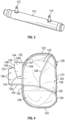
- FIG. 3 illustrates a perspective view of the inflator 110 according to one embodiment of the present disclosure.
- the inflator 110 may be an appropriate airbag inflator for the purpose of inflating the inflatable side airbag cushion 120.
- the inflator 110 can include a gas canister, a chemical container, or other method for generation of inflation gas, and any conduit(s) or ducting (plumbing) for delivering or supplying inflation gas to the inflatable side airbag cushion 120, and other components related to generation and delivery of inflation gas.
- the inflator 110 is in fluid communication with the inflatable side airbag cushion 120.
- the inflator 110 is disposed within the inflatable side airbag cushion 120.
- the inflator is partially disposed within the inflatable side airbag cushion 120.
- the inflator 110 comprises an attachment stud for attaching the inflator 110 to a frame of the seat back 34.
- the inflator 110 comprises a first attachment stud 112 and a second attachment stud 114 that are spaced apart.
- the current disclosure is not so limited, and the inflator 110 may comprise more or less than two attachment studs.
- the attachment studs 112 and 114 are used to attach the side airbag assembly 100 to the frame of the seat back 34 of vehicle seating position 30.
- FIG. 4 illustrates a front view of the inflatable side airbag cushion 120, the wrapper 130, and the cap 140 in an unpackaged configuration.
- FIG. 5 illustrates a rear view of the inflatable side airbag cushion 120, the wrapper 130, and the cap 140 of FIG. 4 in the unpackaged configuration.
- the inflatable side airbag cushion 120 may comprise a substantially oval shape. However, the present disclosure is not so limited and the inflatable side airbag cushion 120 may be circular, triangular, polygonal and/or other shapes.
- the inflatable side airbag cushion 120 may comprise a first lateral end 121, a second lateral end 122, an upper end 123, and a lower end 124.
- One of the lateral ends 121 and 122 may comprise a plurality of apertures 125.
- the plurality of apertures 125 may be spaced apart (e.g., so as to be vertically spaced apart when installed in a vehicle seat) and are configured to receive the plurality of attachment studs 112 and 114 of the inflator 110.
- the number of apertures 125 in the inflatable side airbag cushion 120 may correspond with the number of attachment studs 112 and 114 on the inflator 110.
- the apertures 125 are spaced apart a similar distance as the attachment studs 112 and 114 of the inflator 110 are spaced apart.
- the plurality of apertures 125 are disposed on the second lateral end 122 of the inflatable side airbag cushion 120.
- the plurality of apertures 125 may be disposed on the first lateral end 121 of the inflatable side airbag cushion 120.
- the inflator 110 is disposed within the inflatable side airbag cushion 120. In some embodiments, the inflator 110 is disposed outside the inflatable side airbag cushion 120. In some embodiments, the inflator 110 is partially disposed within and outside the inflatable side airbag cushion 120.
- the inflatable side airbag cushion 120 may be formed from one or more panels 126 of suitable material by means of cutting, folding, bending, turning or otherwise shaping such material, and by application of seams 128 at appropriate locations.
- the seams 128 may be formed by sewing, adhesive, taping, radio frequency (RF) welding, or any other suitable means.
- the seams 128 may be gas impermeable, semipermeable, or permeable, as appropriate.
- the inflatable side airbag cushion 120 may be configured to receive inflation gas from the inflator 110 (not shown) to expand the inflatable side airbag cushion 120 from a packaged state to a deployed state.
- the inflatable side airbag cushion 120 may further comprise a plurality of vents 129 to vent the gas during ride down of the inflatable side airbag cushion 120.
- the inflatable side airbag cushion 120 is configured to collapse into a packaged state. As discussed above, the inflatable side airbag cushion 120 may be folded, rolled, and the like. In one embodiment, the inflatable side airbag cushion 120 may be rolled laterally from the first lateral end 121 toward the second lateral end 122 to form a rolled configuration.
- the wrapper 130 is configured to wrap around the inflatable side airbag cushion 120 and the inflator 110 in the rolled configuration.
- the wrapper 130 comprises a substantially rectangular shape with a first lateral end 131, a second lateral end 132, an upper end 133, and a bottom end 134.
- the first lateral end 131 and the second lateral end 132 may both comprise a plurality of apertures 135 and 136 that are vertically spaced apart.
- the number of apertures 135 on the first lateral end 131 and the number of apertures 136 on the second lateral end 132 correspond with the number of attachment studs 112 and 114 on the inflator 110.
- the apertures 135 and 136 are configured to receive the attachment studs 112 and 114 of the inflator 110.
- the apertures 135 and 136 are vertically spaced apart a similar distance as the attachment studs 112 and 114 of the inflator 110.
- the apertures 135 and 136 may be reinforced by additional material and stitching. As illustrated in FIG. 5 , a reinforcement material 137 is aligned with the plurality of apertures 136 and secured to the wrapper 130 via stitching 139. The reinforcement material 137 and the stitching 139 reinforce the apertures 136 from tearing from the attachment studs 112 and 114 of the inflator 110 before deployment of the inflatable side airbag cushion 120.
- the apertures 135 of the first lateral end 131 of the wrapper 130 are placed on the plurality of attachment studs 112 and 114.
- the wrapper 130 is then wrapped around the inflatable side airbag cushion 120 in the rolled or packaged configuration, and the apertures 136 of the second lateral end 132 are placed on the plurality of attachment studs 112 and 114.
- the inflatable side airbag cushion 120 is held in the rolled or packaged configuration by the wrapper 130 until deployment of the inflatable side airbag cushion 120.
- the wrapper 130 is configured to burst or otherwise break during deployment (and expansion) of the inflatable side airbag cushion 120.
- the wrapper 130 may be formed of a suitable flexible material, such as a ductile fabric material. In some embodiments, the material may comprise a plurality of polymeric fibers.
- the upper end 123 and the lower end 124 of the inflatable side airbag cushion 120 in the rolled configuration may be wrapped by an additional wrapper 138, as illustrated in FIGS. 6 and 7 .
- the additional wrapper 138 may slide over the upper end 133 and another wrapper may slide over the lower end 134.
- only the upper end 133 has the additional wrapper 138 or only the lower end 134 has the additional wrapper 138.
- the additional wrapper 138 is configured to secure the inflatable side airbag cushion 120 in the rolled configuration until deployment.
- the additional wrapper 138 is configured to break during deployment to allow the inflatable side airbag cushion 120 to deploy.
- the additional wrapper 138 is an adhesive that is taped around the upper end 133 and the lower end 134.
- the additional wrapper 138 is configured to break during deployment to allow the inflatable side airbag cushion 120 to deploy.
- the packaged inflatable side airbag cushion 120 comprises the upper end 123 and the lower end 124.
- the cap 140 is configured to enclose one of the ends 123 and 124 of the inflatable side airbag cushion 120. In the illustrated embodiment, the cap 140 encloses the upper end 123.
- the cap 140 may be coupled to the upper end 133 of the wrapper 130. In some embodiments, the cap 140 is integral with the wrapper 130.
- the cap 140 may be formed of a suitable flexible material, such as a ductile fabric material. In some embodiments, the material may comprise a plurality of polymeric fibers.
- the material for the cap 140 and the material for the wrapper 130 may be the same material.
- the cap 140 comprises a single piece or sheet of material that is folded back upon itself along a fold 144 forming a first panel 141 and a second panel 142.
- the first panel 141 is coupled to the upper end 133 of the wrapper 130 in a center portion of the wrapper.
- the second panel 142 may have a greater length (e.g., vertical direction) than the first panel 141.
- the first panel 141 may be coupled to the upper end 133 of the wrapper 130 via stitching, an adhesive, or the like. In some embodiments, the first panel 141 is integral with the wrapper 130.
- the second panel 142 is coupled to one of the plurality of attachment studs 112 and 114 of the inflator 110.
- the second panel 142 may comprise an aperture 143 that is configured to receive one of the attachment studs 112 and 114 of the inflator 110.
- the second panel 142 may comprise a plurality of apertures that are configured to receive a corresponding attachment stud of the plurality of attachment studs 112 and 114 of the inflator 110.
- the number of apertures in the second panel 142 may correspond with the number of attachment studs of the inflator 110.
- the cap 140 may comprise a horizontal stitching seam 146 that extends substantially from a first lateral edge 147 to a second lateral edge 148 of the cap 140.
- the horizontal stitching seam 146 is configured to couple the first panel 141 to the second panel 142.
- the horizontal stitching seam 146 may be disposed a predetermined distance from the fold 144.
- the cap 140 may further comprise a pair of lateral stitching seams 149 that are disposed in the first lateral edge 147 and the second lateral edge 148.
- the lateral stitching seams 149 may extend a majority of the length of the first panel 141.
- the horizontal stitching seam 146 and the lateral stitching seams 149 provide some rigidity to the cap 140 to help prevent the cap 140 from being bent over during the assembly of the seat back 34 of the vehicle seating position 30.
- the cap 140 may have a predetermined amount of stiffness to prevent the upper end of the side airbag assembly 100 from being bent over during the manufacture of the seat back 34.
- the degree of stiffness counters forces on the cap 140 when foam for the seat slides into place on a frame of the seat, discussed below. Thereby preventing an upper end 123 of the side airbag assembly 110 from bending over.
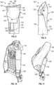
- FIG. 6 illustrates the side airbag assembly 100 in a partially assembled configuration.
- the cap 140 is not pulled over the upper end 123 of the inflatable side airbag cushion 120 in the rolled configuration.
- FIG. 7 illustrates the side airbag assembly 100 in an assembled configuration with the cap 140 encompassing the upper end 123 of the inflatable side airbag cushion 120 in the rolled configuration.
- the aperture 143 of the second panel 142 is placed over the attachment stud 112 of the inflator 110.
- a rigid member 150 may be inserted in between the first panel 141 and the second panel 142 and between the fold 144 and the horizontal stitching seam 146.
- the rigid member 150 may be secured in place by the horizontal stitching seam 146.
- the rigid member 150 is illustrated in phantom lines because it is not visible between the first panel 141 and the second panel 142.
- the rigid member 150 provides rigidity to the cap 140 to help prevent the cap 140 from being bent over during the manufacture of the seat back 34.
- the rigid member 150 may be fabricated from any suitable material that provides enough stiffness to strengthen the cap 140.
- FIG. 8 illustrates a detailed rear view of the side airbag assembly 100 in the assembled configuration with the cap 140 disposed over the upper end 123 of the inflatable side airbag cushion 120.
- FIG. 9 illustrates a detailed side view of the side airbag assembly 100 in the assembled configuration with the cap 140 disposed over the upper end 123 of the inflatable side airbag cushion 120.
- the second panel 142 of the cap may comprise a curve.
- the curve of the second panel 142 may have a radius of curvature R, as illustrated in FIG. 9 .
- the curve may be a compound curve.
- FIG. 10 illustrates the side airbag assembly 100 in the assembled configuration coupled to a frame of the seat back 34 of the vehicle seating position 30. Only a rear view of the side airbag assembly 100 is visible as the front side of the side airbag assembly 100 is coupled to the frame of the seat back 34.
- the side airbag assembly 100 is coupled to the frame via the attachment studs 112 and 114 of the inflator 110 (not shown in FIG. 10 ).
- FIG. 11 illustrates the foam pad 36 attached to the seat back 34.
- the cap 140 is designed to prevent the inflatable side airbag cushion 120 from being bent over when the foam pad 36 is slid into place on the frame of the seat back 34. This is accomplished through a number of different features of the side airbag assembly 100. For example, the stiffness of the cap 140 prevents the inflatable side airbag cushion 120 from being bent over. In addition, the radius of curvature R of the cap 140 guides the foam pad 36 into place on the frame.
- Coupled to and “in communication with” refer to any form of interaction between two or more entities, including mechanical, electrical, magnetic, electromagnetic, fluid, and thermal interaction. Two components may be coupled to each other even though they are not in direct contact with each other.
- a and “an” can be described as one, but not limited to one.
- the disclosure may recite an airbag having "a chamber,” the disclosure also contemplates that the airbag can have two or more chambers.
- the terms “forward” and “rearward” are used with reference to the front and back of the relevant vehicle.
- an airbag cushion that deploys in a rearward direction deploys toward the back of a vehicle.
- other reference terms, such as “horizontal,” are used relative to a vehicle in which an airbag assembly is installed, unless it is clear from context that a different reference frame is intended.
- a term such as “horizontal” is used relative to the vehicle, whether or not the vehicle itself is oriented horizontally (e.g., is positioned upright on level ground) or angled relative to true horizontal (e.g., is positioned on a hill).
- vehicle seating position refers to a position in which an occupant is generally positioned when seated in a seat of a vehicle.
- occupant refers to a person or crash test dummy within a vehicle.
Landscapes
- Engineering & Computer Science (AREA)
- Mechanical Engineering (AREA)
- Air Bags (AREA)
Claims (17)
- Airbag-Einheit (100) in einem verpackten Zustand, umfassend:ein aufblasbares Airbag-Kissen (120) in einer verpackten Konfiguration;einen Gasgenerator (110) in Fluidverbindung mit dem aufblasbaren Airbag-Kissen (120), um Füllgas zuzuführen, um das aufblasbare Airbag-Kissen (120) aufzublasen, der Gasgenerator (110) umfassend einen Befestigungsbolzen (112, 114), um die Airbag-Einheit (100) an einer Seite eines Sitzes zu montieren;eine Hülle (130), die konfiguriert ist, um den Gasgenerator (110) und das aufblasbare Airbag-Kissen (120) in der verpackten Konfiguration zu umwickeln;eine Kappe (140), die mit der Hülle gekoppelt ist, wobei die Kappe konfiguriert ist, um ein erstes Ende (133) des aufblasbaren Airbag-Kissens (120) in der verpackten Konfiguration zu umschließen, um eine Steifigkeit an dem ersten Ende (133) zu erhöhen; unddadurch gekennzeichnet, dassdie Kappe (140) eine einzelne Materialbahn umfasst, die entlang einer Faltung auf sich selbst zurückgefaltet ist, die ein erstes Element (141) und ein zweites Element (142) ausbildet, wobei das erste Element (141) der Kappe (140) an einem zentralen Abschnitt der Hülle (130) gekoppelt ist und das zweite Element der Kappe mit dem Befestigungsbolzen (112, 114) des Gasgenerators gekoppelt ist.
- Airbag-Einheit (100) nach Anspruch 1, wobei die Hülle (130) eine im Wesentlichen rechteckige Form umfasst, um das aufblasbare Airbag-Kissen (120) in der verpackten Konfiguration zu umwickeln, wobei die rechteckige Form ein erstes laterales Ende (131) und ein zweites laterales Ende (132) einschließt, wobei das erste laterale Ende (131) eine erste Öffnung (135) einschließt, um das erste laterale Ende (131) an dem Befestigungsbolzen (112, 114) zu sichern, und das zweite laterale Ende (132) eine zweite Öffnung (136) einschließt, um das zweite laterale Ende (132) an dem Befestigungsbolzen (112, 114) zu sichern.
- Airbag-Einheit (100) nach Anspruch 1, wobei der Gasgenerator (110) eine Vielzahl von Befestigungsbolzen (112, 114) umfasst, die voneinander beabstandet sind, und
wobei die Hülle (130) eine im Wesentlichen rechteckige Form umfasst, die Hülle (130) ein erstes laterales Ende (131) und ein zweites laterales Ende (132) umfasst, die jeweils eine oder mehrere Öffnungen einer Vielzahl von Öffnungen (135, 136) einschließen, die voneinander beabstandet sind, wobei jede Öffnung der einen oder der mehreren Öffnungen konfiguriert ist, um einen der Vielzahl von Befestigungsbolzen (112, 114) des Gasgenerators (110) aufzunehmen. - Airbag-Einheit (100) nach Anspruch 1, wobei die Kappe (140) eine vorbestimmte Menge von Steifigkeit umfasst, um zu verhindern, dass sich ein oberer Abschnitt der Airbag-Einheit (100) umbiegt, wenn ein Schaumstoffpad (36) für den Sitz auf einen Rahmen des Sitzes in Position gleitet.
- Airbag-Einheit (100) nach Anspruch 1, wobei die Kappe (140) ausgebildet ist, um einen Grad von Steifigkeit bereitzustellen, um an der Kappe (140) Kräften entgegenzuwirken, und dadurch zu verhindern, dass sich ein oberer Abschnitt der Airbag-Einheit (100) umbiegt, wenn ein Schaumstoffpad (36) für den Sitz auf einen Rahmen des Sitzes in Position gleitet.
- Airbag-Einheit (100) nach Anspruch 1, wobei das zweite Element (142) eine Öffnung (143) umfasst, die konfiguriert ist, um den Befestigungsbolzen (112, 114) des Gasgenerators (110) aufzunehmen.
- Airbag-Einheit (100) nach Anspruch 1, wobei die Kappe (140) eine horizontale Naht (146) umfasst, die sich im Wesentlichen von einer ersten lateralen Kante (147) der Kappe (140) zu einer zweiten lateralen Kante (148) der Kappe (140) erstreckt.
- Airbag-Einheit (100) nach Anspruch 7, wobei die horizontale Naht einen vorbestimmten Abstand von der Faltung angeordnet ist.
- Airbag-Einheit (100) nach Anspruch 1, wobei die Kappe (140) ein Paar lateraler Nähte (149) umfasst, die sich entlang einer ersten lateralen Kante der Kappe (140) und einer zweiten lateralen Kante der Kappe (140) erstrecken, wobei das Paar lateraler Nähte das erste Element (141) mit dem zweiten Element (142) der Kappe (140) koppelt.
- Airbag-Einheit (100) nach Anspruch 1, wobei das zweite Element (142) eine größere Länge als das erste Element (141) aufweist.
- Airbag-Einheit (100) nach Anspruch 1, wobei das erste Element (141) der Kappe (140) einen Krümmungsradius umfasst, der konfiguriert ist, um Schaumstoff für den Sitz zu führen, wenn der Schaumstoff auf einen Rahmen des Sitzes in Position gleitet, ohne einen oberen Abschnitt der Airbag-Einheit (100) zu biegen.
- Airbag-Einheit (100) nach Anspruch 1, wobei die Hülle (130) und die Kappe (140) aus einem flexiblen Material hergestellt sind.
- Airbag-Einheit (100) nach Anspruch 1, wobei er Gasgenerator (110) zwei Befestigungsbolzen (112, 114) umfasst, die vertikal beabstandet sind.
- Verfahren zum Verpacken einer Seitenairbag-Einheit (100), umfassend:Erhalten eines aufblasbaren Seitenairbag-Kissens (120) mit einem Gasgenerator (110), der mit dem aufblasbaren Seitenairbag-Kissen (120) gekoppelt ist und damit in Fluidverbindung steht, der Gasgenerator (110) umfassend einen Befestigungsbolzen (112, 114), um die Airbag-Einheit (100) an einer Seite eines Sitzes zu montieren;Walzen des aufblasbaren Seitenairbag-Kissens (120);Wickeln des Gasgenerators (110) und des gewalzten aufblasbaren Seitenairbag-Kissens (120) mit einer Hülle (130);Umschließen eines ersten Endes (133) des gewalzten aufblasbaren Seitenairbag-Kissens (120) mit einer Kappe (140), wobei die Kappe (140) eine vorbestimmte Menge von Steifigkeit umfasst, um zu verhindern, dass sich ein oberer Abschnitt des gewalzten aufblasbaren Seitenairbag-Kissens (120) umbiegt, wenn Schaumstoff für einen Sitz auf einen Rahmen des Sitzes in Position gleitet; unddadurch gekennzeichnet, dassdie Kappe (140) eine einzelne Materialbahn umfasst, die entlang einer Faltung auf sich selbst zurückgefaltet ist, die ein erstes Element (141) und ein zweites Element (142) ausbildet, wobei das erste Element (141) der Kappe (140) an einem zentralen Abschnitt der Hülle (130) gekoppelt ist und das zweite Element (142) der Kappe (140) eine Öffnung (143) umfasst, die konfiguriert ist, um den Befestigungsbolzen (112, 114) des Gasgenerators (110) aufzunehmen.
- Verfahren nach Anspruch 14, wobei der Gasgenerator (110) zwei Befestigungsbolzen (112, 114) umfasst, um die Seitenairbag-Einheit (100) an einer Seite eines Sitzes eines Fahrzeugs zu montieren, wobei die zwei Befestigungsbolzen (112, 114) vertikal beabstandet sind.
- Verfahren nach Anspruch 15, wobei die Hülle (130) eine im Wesentlichen rechteckige Form umfasst, die Hülle (130) ein erstes laterales Ende (131) und ein zweites laterales Ende (132) mit zwei Öffnungen (135, 136) umfasst, die in dem ersten lateralen Ende (131) und dem zweiten lateralen Ende (132) angeordnet sind, wobei die Öffnungen vertikal beabstandet sind, wobei jede Öffnung (135, 136) in jedem Ende (131, 132) konfiguriert ist, um einen der zwei Befestigungsbolzen (112, 114) des Gasgenerators (110) aufzunehmen.
- Verfahren nach Anspruch 14, ferner umfassend das Montieren der Seitenairbag-Einheit (100) an einer Seite eines Sitzes eines Fahrzeugs.
Applications Claiming Priority (1)
| Application Number | Priority Date | Filing Date | Title |
|---|---|---|---|
| US17/231,827 US11299120B1 (en) | 2021-04-15 | 2021-04-15 | Side airbag assemblies and methods of assembly |
Publications (2)
| Publication Number | Publication Date |
|---|---|
| EP4079582A1 EP4079582A1 (de) | 2022-10-26 |
| EP4079582B1 true EP4079582B1 (de) | 2023-12-06 |
Family
ID=81123769
Family Applications (1)
| Application Number | Title | Priority Date | Filing Date |
|---|---|---|---|
| EP22166270.3A Active EP4079582B1 (de) | 2021-04-15 | 2022-04-01 | Seitenairbaganordnungen und montageverfahren |
Country Status (5)
| Country | Link |
|---|---|
| US (1) | US11299120B1 (de) |
| EP (1) | EP4079582B1 (de) |
| JP (1) | JP7333441B2 (de) |
| KR (1) | KR102767080B1 (de) |
| CN (1) | CN115214519B (de) |
Families Citing this family (2)
| Publication number | Priority date | Publication date | Assignee | Title |
|---|---|---|---|---|
| USD1020601S1 (en) * | 2020-11-30 | 2024-04-02 | Zoox, Inc. | Vehicle airbag system |
| US11518338B1 (en) * | 2022-01-13 | 2022-12-06 | Autoliv Asp, Inc. | Automotive airbag systems with a securement wrapper and a packaging wrapper |
Family Cites Families (35)
| Publication number | Priority date | Publication date | Assignee | Title |
|---|---|---|---|---|
| JP2785673B2 (ja) * | 1994-01-31 | 1998-08-13 | 池田物産株式会社 | エアバッグ装置のエアバッグカバー及びエアバッグカバーの取付方法 |
| DE9408908U1 (de) * | 1994-05-31 | 1994-11-17 | Trw Repa Gmbh | Gassack-Schutzvorrichtung |
| US5556128A (en) * | 1994-11-24 | 1996-09-17 | Volkswagen Ag | Safety arrangement for a vehicle occupant |
| JPH08282418A (ja) * | 1995-04-07 | 1996-10-29 | Nippon Seiko Kk | エアバッグ装置 |
| JP4181997B2 (ja) * | 2002-01-04 | 2008-11-19 | タカターペトリ(ウルム)ゲーエムベーハー | 側方エアバッグモジュールのためのガス流分配器 |
| US20030168836A1 (en) * | 2002-03-11 | 2003-09-11 | Eiji Sato | Side airbag apparatus |
| DE10235128A1 (de) * | 2002-08-01 | 2004-02-19 | Autoliv Development Ab | Für zwei Personen vorgesehene Airbageinrichtung |
| JP4059124B2 (ja) | 2003-03-27 | 2008-03-12 | 豊田合成株式会社 | サイドエアバッグ装置及びそれに用いるラッピングシート |
| JP4793924B2 (ja) * | 2006-06-12 | 2011-10-12 | タカタ株式会社 | 側突用エアバッグ、側突用エアバッグ装置、車両用シート |
| JP5199604B2 (ja) * | 2006-06-12 | 2013-05-15 | タカタ株式会社 | 側突用エアバッグ装置、車両用シート、インフレータのガス分配器 |
| DE102006031117B4 (de) * | 2006-07-05 | 2017-07-06 | Lear Corp. | Verfahren zum Zusammenbau einer Airbag-Baugruppe und Airbag-Baugruppe |
| JP2009040229A (ja) * | 2007-08-09 | 2009-02-26 | Takata Corp | 側突用エアバッグ装置 |
| JP4546515B2 (ja) * | 2007-11-27 | 2010-09-15 | 本田技研工業株式会社 | 車両用エアバッグ装置 |
| JP5125596B2 (ja) * | 2008-02-22 | 2013-01-23 | 豊田合成株式会社 | 側突用エアバッグ装置 |
| DE102008019730A1 (de) * | 2008-03-04 | 2009-09-10 | Takata-Petri Ag | Airbagabdeckung zur Aufnahme eines Gassackpaketes für ein Airbagmodul eines Kraftfahrzeugs sowie Verfahren zu deren Herstellung |
| DE102009036800A1 (de) * | 2008-08-12 | 2010-02-18 | Dalphimetal España S.A. | Gassackmodul mit Gasverteilungselement |
| JP5163476B2 (ja) * | 2008-10-14 | 2013-03-13 | 豊田合成株式会社 | サイドエアバッグ装置 |
| US8408582B2 (en) * | 2010-06-23 | 2013-04-02 | Autoliv Asp, Inc. | Inflatable airbag assemblies with heat shields |
| DE102010039902A1 (de) * | 2010-08-27 | 2012-03-01 | Takata-Petri Ag | Vorrichtungen für Personen-Schutzsysteme eines Fahrzeugs |
| JP5692190B2 (ja) * | 2012-09-04 | 2015-04-01 | トヨタ自動車株式会社 | 車両用サイドエアバッグ装置及びサイドエアバッグの製造方法 |
| JP5692197B2 (ja) * | 2012-10-10 | 2015-04-01 | トヨタ自動車株式会社 | サイドエアバッグ装置を備えた車両用シート及びサイドエアバッグ装置の車両用シートへの組付方法 |
| JP6070217B2 (ja) * | 2013-01-25 | 2017-02-01 | 豊田合成株式会社 | サイドエアバッグ装置 |
| KR102064002B1 (ko) * | 2013-05-07 | 2020-01-08 | 현대모비스 주식회사 | 차량의 사이드 에어백 |
| JP5923059B2 (ja) * | 2013-05-21 | 2016-05-24 | オートリブ ディベロップメント エービー | サイドエアバッグ装置の製造方法 |
| JP5960667B2 (ja) * | 2013-10-07 | 2016-08-02 | オートリブ ディベロップメント エービー | エアバッグ装置 |
| US9108589B2 (en) * | 2013-11-02 | 2015-08-18 | Autoliv Asp, Inc. | Protective flap for airbags |
| JP6149849B2 (ja) * | 2014-11-25 | 2017-06-21 | トヨタ自動車株式会社 | 車両用ファーサイドエアバッグ装置 |
| CN107428306B (zh) * | 2015-04-13 | 2019-10-29 | 奥托立夫开发公司 | 帘式气囊装置和帘式气囊装置的制造方法 |
| JP6799909B2 (ja) * | 2015-11-11 | 2020-12-16 | Joyson Safety Systems Japan株式会社 | エアバッグ装置 |
| KR102209228B1 (ko) * | 2017-02-27 | 2021-01-29 | 아우토리브 디벨롭먼트 아베 | 사이드 에어백 장치 |
| JP6801621B2 (ja) * | 2017-09-28 | 2020-12-16 | 豊田合成株式会社 | サイドエアバッグ装置 |
| US10384634B2 (en) * | 2017-12-05 | 2019-08-20 | Autoliv Asp, Inc. | Side airbag with accordion pelvis fold |
| US10994687B2 (en) * | 2018-12-11 | 2021-05-04 | Autoliv Asp, Inc. | Airbag compression wrappers and related airbag assemblies |
| CN210212319U (zh) * | 2019-07-12 | 2020-03-31 | 延锋汽车智能安全系统(常熟)有限公司 | 座椅侧气囊装置及其隔热构件 |
| US11292414B2 (en) * | 2020-07-07 | 2022-04-05 | ZF Passive Safety Systems US Inc. | Airbag packaging wrap |
-
2021
- 2021-04-15 US US17/231,827 patent/US11299120B1/en active Active
-
2022
- 2022-03-21 CN CN202210275473.7A patent/CN115214519B/zh active Active
- 2022-04-01 EP EP22166270.3A patent/EP4079582B1/de active Active
- 2022-04-04 JP JP2022062387A patent/JP7333441B2/ja active Active
- 2022-04-07 KR KR1020220043360A patent/KR102767080B1/ko active Active
Also Published As
| Publication number | Publication date |
|---|---|
| US11299120B1 (en) | 2022-04-12 |
| JP2022164591A (ja) | 2022-10-27 |
| CN115214519B (zh) | 2023-10-27 |
| EP4079582A1 (de) | 2022-10-26 |
| KR20220142931A (ko) | 2022-10-24 |
| JP7333441B2 (ja) | 2023-08-24 |
| CN115214519A (zh) | 2022-10-21 |
| KR102767080B1 (ko) | 2025-02-14 |
Similar Documents
| Publication | Publication Date | Title |
|---|---|---|
| US10583799B2 (en) | Overhead inflatable airbag assembly | |
| US10703325B2 (en) | Multi-chambered side airbag assemblies | |
| JP6681893B2 (ja) | エアバッグモジュール | |
| US8371612B2 (en) | Inflatable airbag assemblies with lateral and longitudinal tethers | |
| US11833990B2 (en) | Side airbag device, vehicle seat provided with same, and method for manufacturing side airbag device | |
| EP2496446B1 (de) | Fahrzeug mit einem niedrig montierten aufblasbaren knie-airbag mit seriellen kammern | |
| JP6131935B2 (ja) | 車両用ファーサイドエアバッグ装置 | |
| EP2475555B1 (de) | Montagebaugruppen mit umhüllungen für aufblasbare vorhangairbags | |
| US7823922B2 (en) | Tether systems for inflatable cushions | |
| KR101391439B1 (ko) | 팽창기 브라켓을 구비한 팽창가능 에어백 조립체 | |
| EP3844034B1 (de) | Knieairbaganordnungen | |
| US20160311393A1 (en) | Frontal airbag assemblies | |
| US8814204B2 (en) | Automobile seat in which side airbag device is installed | |
| US20050082797A1 (en) | Expanding net integral with an inflatable airbag curtain | |
| US11267433B2 (en) | Side airbag device and vehicle seat provided with same | |
| EP4079582B1 (de) | Seitenairbaganordnungen und montageverfahren | |
| KR20200137994A (ko) | 사이드 에어백 장치 | |
| US20070052212A1 (en) | Extended inflatable coverage of inflatable curtains | |
| US20040239082A1 (en) | Overhead airbag system | |
| WO2023003743A1 (en) | Apparatus for covering a windshield opening of a vehicle | |
| US11623599B2 (en) | Airbag with inflator attachment | |
| WO2023113884A1 (en) | Inflatable curtain airbag with bi-roll package state | |
| CN220483242U (zh) | 安全气囊 |
Legal Events
| Date | Code | Title | Description |
|---|---|---|---|
| PUAI | Public reference made under article 153(3) epc to a published international application that has entered the european phase |
Free format text: ORIGINAL CODE: 0009012 |
|
| STAA | Information on the status of an ep patent application or granted ep patent |
Free format text: STATUS: REQUEST FOR EXAMINATION WAS MADE |
|
| 17P | Request for examination filed |
Effective date: 20220401 |
|
| AK | Designated contracting states |
Kind code of ref document: A1 Designated state(s): AL AT BE BG CH CY CZ DE DK EE ES FI FR GB GR HR HU IE IS IT LI LT LU LV MC MK MT NL NO PL PT RO RS SE SI SK SM TR |
|
| STAA | Information on the status of an ep patent application or granted ep patent |
Free format text: STATUS: EXAMINATION IS IN PROGRESS |
|
| 17Q | First examination report despatched |
Effective date: 20230206 |
|
| GRAP | Despatch of communication of intention to grant a patent |
Free format text: ORIGINAL CODE: EPIDOSNIGR1 |
|
| STAA | Information on the status of an ep patent application or granted ep patent |
Free format text: STATUS: GRANT OF PATENT IS INTENDED |
|
| INTG | Intention to grant announced |
Effective date: 20230710 |
|
| GRAS | Grant fee paid |
Free format text: ORIGINAL CODE: EPIDOSNIGR3 |
|
| GRAA | (expected) grant |
Free format text: ORIGINAL CODE: 0009210 |
|
| STAA | Information on the status of an ep patent application or granted ep patent |
Free format text: STATUS: THE PATENT HAS BEEN GRANTED |
|
| AK | Designated contracting states |
Kind code of ref document: B1 Designated state(s): AL AT BE BG CH CY CZ DE DK EE ES FI FR GB GR HR HU IE IS IT LI LT LU LV MC MK MT NL NO PL PT RO RS SE SI SK SM TR |
|
| REG | Reference to a national code |
Ref country code: GB Ref legal event code: FG4D |
|
| REG | Reference to a national code |
Ref country code: CH Ref legal event code: EP |
|
| REG | Reference to a national code |
Ref country code: DE Ref legal event code: R096 Ref document number: 602022001201 Country of ref document: DE |
|
| REG | Reference to a national code |
Ref country code: IE Ref legal event code: FG4D |
|
| REG | Reference to a national code |
Ref country code: LT Ref legal event code: MG9D |
|
| PG25 | Lapsed in a contracting state [announced via postgrant information from national office to epo] |
Ref country code: GR Free format text: LAPSE BECAUSE OF FAILURE TO SUBMIT A TRANSLATION OF THE DESCRIPTION OR TO PAY THE FEE WITHIN THE PRESCRIBED TIME-LIMIT Effective date: 20240307 |
|
| REG | Reference to a national code |
Ref country code: NL Ref legal event code: MP Effective date: 20231206 |
|
| PG25 | Lapsed in a contracting state [announced via postgrant information from national office to epo] |
Ref country code: LT Free format text: LAPSE BECAUSE OF FAILURE TO SUBMIT A TRANSLATION OF THE DESCRIPTION OR TO PAY THE FEE WITHIN THE PRESCRIBED TIME-LIMIT Effective date: 20231206 |
|
| PG25 | Lapsed in a contracting state [announced via postgrant information from national office to epo] |
Ref country code: ES Free format text: LAPSE BECAUSE OF FAILURE TO SUBMIT A TRANSLATION OF THE DESCRIPTION OR TO PAY THE FEE WITHIN THE PRESCRIBED TIME-LIMIT Effective date: 20231206 |
|
| PG25 | Lapsed in a contracting state [announced via postgrant information from national office to epo] |
Ref country code: LT Free format text: LAPSE BECAUSE OF FAILURE TO SUBMIT A TRANSLATION OF THE DESCRIPTION OR TO PAY THE FEE WITHIN THE PRESCRIBED TIME-LIMIT Effective date: 20231206 Ref country code: GR Free format text: LAPSE BECAUSE OF FAILURE TO SUBMIT A TRANSLATION OF THE DESCRIPTION OR TO PAY THE FEE WITHIN THE PRESCRIBED TIME-LIMIT Effective date: 20240307 Ref country code: ES Free format text: LAPSE BECAUSE OF FAILURE TO SUBMIT A TRANSLATION OF THE DESCRIPTION OR TO PAY THE FEE WITHIN THE PRESCRIBED TIME-LIMIT Effective date: 20231206 Ref country code: BG Free format text: LAPSE BECAUSE OF FAILURE TO SUBMIT A TRANSLATION OF THE DESCRIPTION OR TO PAY THE FEE WITHIN THE PRESCRIBED TIME-LIMIT Effective date: 20240306 |
|
| REG | Reference to a national code |
Ref country code: AT Ref legal event code: MK05 Ref document number: 1638098 Country of ref document: AT Kind code of ref document: T Effective date: 20231206 |
|
| PG25 | Lapsed in a contracting state [announced via postgrant information from national office to epo] |
Ref country code: NL Free format text: LAPSE BECAUSE OF FAILURE TO SUBMIT A TRANSLATION OF THE DESCRIPTION OR TO PAY THE FEE WITHIN THE PRESCRIBED TIME-LIMIT Effective date: 20231206 |
|
| PG25 | Lapsed in a contracting state [announced via postgrant information from national office to epo] |
Ref country code: SE Free format text: LAPSE BECAUSE OF FAILURE TO SUBMIT A TRANSLATION OF THE DESCRIPTION OR TO PAY THE FEE WITHIN THE PRESCRIBED TIME-LIMIT Effective date: 20231206 Ref country code: RS Free format text: LAPSE BECAUSE OF FAILURE TO SUBMIT A TRANSLATION OF THE DESCRIPTION OR TO PAY THE FEE WITHIN THE PRESCRIBED TIME-LIMIT Effective date: 20231206 Ref country code: NO Free format text: LAPSE BECAUSE OF FAILURE TO SUBMIT A TRANSLATION OF THE DESCRIPTION OR TO PAY THE FEE WITHIN THE PRESCRIBED TIME-LIMIT Effective date: 20240306 Ref country code: NL Free format text: LAPSE BECAUSE OF FAILURE TO SUBMIT A TRANSLATION OF THE DESCRIPTION OR TO PAY THE FEE WITHIN THE PRESCRIBED TIME-LIMIT Effective date: 20231206 Ref country code: LV Free format text: LAPSE BECAUSE OF FAILURE TO SUBMIT A TRANSLATION OF THE DESCRIPTION OR TO PAY THE FEE WITHIN THE PRESCRIBED TIME-LIMIT Effective date: 20231206 Ref country code: HR Free format text: LAPSE BECAUSE OF FAILURE TO SUBMIT A TRANSLATION OF THE DESCRIPTION OR TO PAY THE FEE WITHIN THE PRESCRIBED TIME-LIMIT Effective date: 20231206 |
|
| PG25 | Lapsed in a contracting state [announced via postgrant information from national office to epo] |
Ref country code: IS Free format text: LAPSE BECAUSE OF FAILURE TO SUBMIT A TRANSLATION OF THE DESCRIPTION OR TO PAY THE FEE WITHIN THE PRESCRIBED TIME-LIMIT Effective date: 20240406 |
|
| PG25 | Lapsed in a contracting state [announced via postgrant information from national office to epo] |
Ref country code: CZ Free format text: LAPSE BECAUSE OF FAILURE TO SUBMIT A TRANSLATION OF THE DESCRIPTION OR TO PAY THE FEE WITHIN THE PRESCRIBED TIME-LIMIT Effective date: 20231206 Ref country code: AT Free format text: LAPSE BECAUSE OF FAILURE TO SUBMIT A TRANSLATION OF THE DESCRIPTION OR TO PAY THE FEE WITHIN THE PRESCRIBED TIME-LIMIT Effective date: 20231206 |
|
| PG25 | Lapsed in a contracting state [announced via postgrant information from national office to epo] |
Ref country code: SK Free format text: LAPSE BECAUSE OF FAILURE TO SUBMIT A TRANSLATION OF THE DESCRIPTION OR TO PAY THE FEE WITHIN THE PRESCRIBED TIME-LIMIT Effective date: 20231206 |
|
| PG25 | Lapsed in a contracting state [announced via postgrant information from national office to epo] |
Ref country code: SM Free format text: LAPSE BECAUSE OF FAILURE TO SUBMIT A TRANSLATION OF THE DESCRIPTION OR TO PAY THE FEE WITHIN THE PRESCRIBED TIME-LIMIT Effective date: 20231206 Ref country code: SK Free format text: LAPSE BECAUSE OF FAILURE TO SUBMIT A TRANSLATION OF THE DESCRIPTION OR TO PAY THE FEE WITHIN THE PRESCRIBED TIME-LIMIT Effective date: 20231206 Ref country code: RO Free format text: LAPSE BECAUSE OF FAILURE TO SUBMIT A TRANSLATION OF THE DESCRIPTION OR TO PAY THE FEE WITHIN THE PRESCRIBED TIME-LIMIT Effective date: 20231206 Ref country code: IT Free format text: LAPSE BECAUSE OF FAILURE TO SUBMIT A TRANSLATION OF THE DESCRIPTION OR TO PAY THE FEE WITHIN THE PRESCRIBED TIME-LIMIT Effective date: 20231206 Ref country code: IS Free format text: LAPSE BECAUSE OF FAILURE TO SUBMIT A TRANSLATION OF THE DESCRIPTION OR TO PAY THE FEE WITHIN THE PRESCRIBED TIME-LIMIT Effective date: 20240406 Ref country code: EE Free format text: LAPSE BECAUSE OF FAILURE TO SUBMIT A TRANSLATION OF THE DESCRIPTION OR TO PAY THE FEE WITHIN THE PRESCRIBED TIME-LIMIT Effective date: 20231206 Ref country code: CZ Free format text: LAPSE BECAUSE OF FAILURE TO SUBMIT A TRANSLATION OF THE DESCRIPTION OR TO PAY THE FEE WITHIN THE PRESCRIBED TIME-LIMIT Effective date: 20231206 Ref country code: AT Free format text: LAPSE BECAUSE OF FAILURE TO SUBMIT A TRANSLATION OF THE DESCRIPTION OR TO PAY THE FEE WITHIN THE PRESCRIBED TIME-LIMIT Effective date: 20231206 |
|
| PG25 | Lapsed in a contracting state [announced via postgrant information from national office to epo] |
Ref country code: PL Free format text: LAPSE BECAUSE OF FAILURE TO SUBMIT A TRANSLATION OF THE DESCRIPTION OR TO PAY THE FEE WITHIN THE PRESCRIBED TIME-LIMIT Effective date: 20231206 Ref country code: PT Free format text: LAPSE BECAUSE OF FAILURE TO SUBMIT A TRANSLATION OF THE DESCRIPTION OR TO PAY THE FEE WITHIN THE PRESCRIBED TIME-LIMIT Effective date: 20240408 |
|
| PG25 | Lapsed in a contracting state [announced via postgrant information from national office to epo] |
Ref country code: PT Free format text: LAPSE BECAUSE OF FAILURE TO SUBMIT A TRANSLATION OF THE DESCRIPTION OR TO PAY THE FEE WITHIN THE PRESCRIBED TIME-LIMIT Effective date: 20240408 Ref country code: PL Free format text: LAPSE BECAUSE OF FAILURE TO SUBMIT A TRANSLATION OF THE DESCRIPTION OR TO PAY THE FEE WITHIN THE PRESCRIBED TIME-LIMIT Effective date: 20231206 |
|
| REG | Reference to a national code |
Ref country code: DE Ref legal event code: R097 Ref document number: 602022001201 Country of ref document: DE |
|
| PG25 | Lapsed in a contracting state [announced via postgrant information from national office to epo] |
Ref country code: DK Free format text: LAPSE BECAUSE OF FAILURE TO SUBMIT A TRANSLATION OF THE DESCRIPTION OR TO PAY THE FEE WITHIN THE PRESCRIBED TIME-LIMIT Effective date: 20231206 |
|
| PLBE | No opposition filed within time limit |
Free format text: ORIGINAL CODE: 0009261 |
|
| STAA | Information on the status of an ep patent application or granted ep patent |
Free format text: STATUS: NO OPPOSITION FILED WITHIN TIME LIMIT |
|
| PG25 | Lapsed in a contracting state [announced via postgrant information from national office to epo] |
Ref country code: SI Free format text: LAPSE BECAUSE OF FAILURE TO SUBMIT A TRANSLATION OF THE DESCRIPTION OR TO PAY THE FEE WITHIN THE PRESCRIBED TIME-LIMIT Effective date: 20231206 |
|
| PG25 | Lapsed in a contracting state [announced via postgrant information from national office to epo] |
Ref country code: SI Free format text: LAPSE BECAUSE OF FAILURE TO SUBMIT A TRANSLATION OF THE DESCRIPTION OR TO PAY THE FEE WITHIN THE PRESCRIBED TIME-LIMIT Effective date: 20231206 Ref country code: DK Free format text: LAPSE BECAUSE OF FAILURE TO SUBMIT A TRANSLATION OF THE DESCRIPTION OR TO PAY THE FEE WITHIN THE PRESCRIBED TIME-LIMIT Effective date: 20231206 |
|
| 26N | No opposition filed |
Effective date: 20240909 |
|
| PG25 | Lapsed in a contracting state [announced via postgrant information from national office to epo] |
Ref country code: MC Free format text: LAPSE BECAUSE OF FAILURE TO SUBMIT A TRANSLATION OF THE DESCRIPTION OR TO PAY THE FEE WITHIN THE PRESCRIBED TIME-LIMIT Effective date: 20231206 |
|
| PG25 | Lapsed in a contracting state [announced via postgrant information from national office to epo] |
Ref country code: MC Free format text: LAPSE BECAUSE OF FAILURE TO SUBMIT A TRANSLATION OF THE DESCRIPTION OR TO PAY THE FEE WITHIN THE PRESCRIBED TIME-LIMIT Effective date: 20231206 |
|
| PG25 | Lapsed in a contracting state [announced via postgrant information from national office to epo] |
Ref country code: LU Free format text: LAPSE BECAUSE OF NON-PAYMENT OF DUE FEES Effective date: 20240401 |
|
| REG | Reference to a national code |
Ref country code: BE Ref legal event code: MM Effective date: 20240430 |
|
| PG25 | Lapsed in a contracting state [announced via postgrant information from national office to epo] |
Ref country code: LU Free format text: LAPSE BECAUSE OF NON-PAYMENT OF DUE FEES Effective date: 20240401 |
|
| PG25 | Lapsed in a contracting state [announced via postgrant information from national office to epo] |
Ref country code: BE Free format text: LAPSE BECAUSE OF NON-PAYMENT OF DUE FEES Effective date: 20240430 |
|
| PG25 | Lapsed in a contracting state [announced via postgrant information from national office to epo] |
Ref country code: BE Free format text: LAPSE BECAUSE OF NON-PAYMENT OF DUE FEES Effective date: 20240430 |
|
| PG25 | Lapsed in a contracting state [announced via postgrant information from national office to epo] |
Ref country code: IE Free format text: LAPSE BECAUSE OF NON-PAYMENT OF DUE FEES Effective date: 20240401 |
|
| PGFP | Annual fee paid to national office [announced via postgrant information from national office to epo] |
Ref country code: DE Payment date: 20250428 Year of fee payment: 4 |
|
| PGFP | Annual fee paid to national office [announced via postgrant information from national office to epo] |
Ref country code: FR Payment date: 20250424 Year of fee payment: 4 |
|
| PG25 | Lapsed in a contracting state [announced via postgrant information from national office to epo] |
Ref country code: CY Free format text: LAPSE BECAUSE OF FAILURE TO SUBMIT A TRANSLATION OF THE DESCRIPTION OR TO PAY THE FEE WITHIN THE PRESCRIBED TIME-LIMIT; INVALID AB INITIO Effective date: 20220401 |
|
| PG25 | Lapsed in a contracting state [announced via postgrant information from national office to epo] |
Ref country code: FI Free format text: LAPSE BECAUSE OF FAILURE TO SUBMIT A TRANSLATION OF THE DESCRIPTION OR TO PAY THE FEE WITHIN THE PRESCRIBED TIME-LIMIT Effective date: 20231207 |
|
| REG | Reference to a national code |
Ref country code: CH Ref legal event code: H13 Free format text: ST27 STATUS EVENT CODE: U-0-0-H10-H13 (AS PROVIDED BY THE NATIONAL OFFICE) Effective date: 20251125 |
|
| PG25 | Lapsed in a contracting state [announced via postgrant information from national office to epo] |
Ref country code: TR Free format text: LAPSE BECAUSE OF FAILURE TO SUBMIT A TRANSLATION OF THE DESCRIPTION OR TO PAY THE FEE WITHIN THE PRESCRIBED TIME-LIMIT Effective date: 20231206 |
|
| PG25 | Lapsed in a contracting state [announced via postgrant information from national office to epo] |
Ref country code: CH Free format text: LAPSE BECAUSE OF NON-PAYMENT OF DUE FEES Effective date: 20250430 |