EP4079582B1 - Side airbag assemblies and methods of assembly - Google Patents
Side airbag assemblies and methods of assembly Download PDFInfo
- Publication number
- EP4079582B1 EP4079582B1 EP22166270.3A EP22166270A EP4079582B1 EP 4079582 B1 EP4079582 B1 EP 4079582B1 EP 22166270 A EP22166270 A EP 22166270A EP 4079582 B1 EP4079582 B1 EP 4079582B1
- Authority
- EP
- European Patent Office
- Prior art keywords
- cap
- inflator
- airbag assembly
- panel
- inflatable
- Prior art date
- Legal status (The legal status is an assumption and is not a legal conclusion. Google has not performed a legal analysis and makes no representation as to the accuracy of the status listed.)
- Active
Links
- 238000000034 method Methods 0.000 title claims description 8
- 230000000712 assembly Effects 0.000 title description 4
- 238000000429 assembly Methods 0.000 title description 4
- 239000000463 material Substances 0.000 claims description 19
- 239000006260 foam Substances 0.000 claims description 11
- 239000012530 fluid Substances 0.000 claims description 8
- 238000004891 communication Methods 0.000 claims description 7
- 238000005452 bending Methods 0.000 claims description 6
- 238000004806 packaging method and process Methods 0.000 claims description 2
- 238000005096 rolling process Methods 0.000 claims 1
- 230000003993 interaction Effects 0.000 description 4
- 239000000853 adhesive Substances 0.000 description 3
- 230000001070 adhesive effect Effects 0.000 description 3
- 230000001960 triggered effect Effects 0.000 description 3
- 239000004744 fabric Substances 0.000 description 2
- 239000000835 fiber Substances 0.000 description 2
- 238000009434 installation Methods 0.000 description 2
- 210000003127 knee Anatomy 0.000 description 2
- 238000004519 manufacturing process Methods 0.000 description 2
- 230000002787 reinforcement Effects 0.000 description 2
- 208000027418 Wounds and injury Diseases 0.000 description 1
- 150000001875 compounds Chemical class 0.000 description 1
- 238000005520 cutting process Methods 0.000 description 1
- 230000006378 damage Effects 0.000 description 1
- 208000014674 injury Diseases 0.000 description 1
- 210000002414 leg Anatomy 0.000 description 1
- 239000007788 liquid Substances 0.000 description 1
- 238000009428 plumbing Methods 0.000 description 1
- 230000001681 protective effect Effects 0.000 description 1
- 230000000717 retained effect Effects 0.000 description 1
- 238000009958 sewing Methods 0.000 description 1
- 238000007493 shaping process Methods 0.000 description 1
- 239000000126 substance Substances 0.000 description 1
- 230000007704 transition Effects 0.000 description 1
- 238000003466 welding Methods 0.000 description 1
Images


Classifications
-
- B—PERFORMING OPERATIONS; TRANSPORTING
- B60—VEHICLES IN GENERAL
- B60R—VEHICLES, VEHICLE FITTINGS, OR VEHICLE PARTS, NOT OTHERWISE PROVIDED FOR
- B60R21/00—Arrangements or fittings on vehicles for protecting or preventing injuries to occupants or pedestrians in case of accidents or other traffic risks
- B60R21/02—Occupant safety arrangements or fittings, e.g. crash pads
- B60R21/16—Inflatable occupant restraints or confinements designed to inflate upon impact or impending impact, e.g. air bags
- B60R21/20—Arrangements for storing inflatable members in their non-use or deflated condition; Arrangement or mounting of air bag modules or components
- B60R21/207—Arrangements for storing inflatable members in their non-use or deflated condition; Arrangement or mounting of air bag modules or components in vehicle seats
-
- B—PERFORMING OPERATIONS; TRANSPORTING
- B60—VEHICLES IN GENERAL
- B60R—VEHICLES, VEHICLE FITTINGS, OR VEHICLE PARTS, NOT OTHERWISE PROVIDED FOR
- B60R21/00—Arrangements or fittings on vehicles for protecting or preventing injuries to occupants or pedestrians in case of accidents or other traffic risks
- B60R21/02—Occupant safety arrangements or fittings, e.g. crash pads
- B60R21/16—Inflatable occupant restraints or confinements designed to inflate upon impact or impending impact, e.g. air bags
- B60R21/20—Arrangements for storing inflatable members in their non-use or deflated condition; Arrangement or mounting of air bag modules or components
- B60R21/201—Packaging straps or envelopes for inflatable members
-
- B—PERFORMING OPERATIONS; TRANSPORTING
- B60—VEHICLES IN GENERAL
- B60R—VEHICLES, VEHICLE FITTINGS, OR VEHICLE PARTS, NOT OTHERWISE PROVIDED FOR
- B60R21/00—Arrangements or fittings on vehicles for protecting or preventing injuries to occupants or pedestrians in case of accidents or other traffic risks
- B60R21/02—Occupant safety arrangements or fittings, e.g. crash pads
- B60R21/16—Inflatable occupant restraints or confinements designed to inflate upon impact or impending impact, e.g. air bags
- B60R21/20—Arrangements for storing inflatable members in their non-use or deflated condition; Arrangement or mounting of air bag modules or components
- B60R21/215—Arrangements for storing inflatable members in their non-use or deflated condition; Arrangement or mounting of air bag modules or components characterised by the covers for the inflatable member
-
- B—PERFORMING OPERATIONS; TRANSPORTING
- B60—VEHICLES IN GENERAL
- B60R—VEHICLES, VEHICLE FITTINGS, OR VEHICLE PARTS, NOT OTHERWISE PROVIDED FOR
- B60R21/00—Arrangements or fittings on vehicles for protecting or preventing injuries to occupants or pedestrians in case of accidents or other traffic risks
- B60R21/02—Occupant safety arrangements or fittings, e.g. crash pads
- B60R21/16—Inflatable occupant restraints or confinements designed to inflate upon impact or impending impact, e.g. air bags
- B60R21/20—Arrangements for storing inflatable members in their non-use or deflated condition; Arrangement or mounting of air bag modules or components
- B60R21/217—Inflation fluid source retainers, e.g. reaction canisters; Connection of bags, covers, diffusers or inflation fluid sources therewith or together
- B60R21/2176—Inflation fluid source retainers, e.g. reaction canisters; Connection of bags, covers, diffusers or inflation fluid sources therewith or together the air bag components being completely enclosed in a soft or semi-rigid housing or cover
-
- B—PERFORMING OPERATIONS; TRANSPORTING
- B60—VEHICLES IN GENERAL
- B60R—VEHICLES, VEHICLE FITTINGS, OR VEHICLE PARTS, NOT OTHERWISE PROVIDED FOR
- B60R21/00—Arrangements or fittings on vehicles for protecting or preventing injuries to occupants or pedestrians in case of accidents or other traffic risks
- B60R21/02—Occupant safety arrangements or fittings, e.g. crash pads
- B60R21/16—Inflatable occupant restraints or confinements designed to inflate upon impact or impending impact, e.g. air bags
- B60R21/23—Inflatable members
- B60R21/231—Inflatable members characterised by their shape, construction or spatial configuration
- B60R21/23138—Inflatable members characterised by their shape, construction or spatial configuration specially adapted for side protection
-
- B—PERFORMING OPERATIONS; TRANSPORTING
- B60—VEHICLES IN GENERAL
- B60R—VEHICLES, VEHICLE FITTINGS, OR VEHICLE PARTS, NOT OTHERWISE PROVIDED FOR
- B60R21/00—Arrangements or fittings on vehicles for protecting or preventing injuries to occupants or pedestrians in case of accidents or other traffic risks
- B60R21/02—Occupant safety arrangements or fittings, e.g. crash pads
- B60R21/16—Inflatable occupant restraints or confinements designed to inflate upon impact or impending impact, e.g. air bags
- B60R21/23—Inflatable members
- B60R21/237—Inflatable members characterised by the way they are folded
-
- B—PERFORMING OPERATIONS; TRANSPORTING
- B60—VEHICLES IN GENERAL
- B60R—VEHICLES, VEHICLE FITTINGS, OR VEHICLE PARTS, NOT OTHERWISE PROVIDED FOR
- B60R21/00—Arrangements or fittings on vehicles for protecting or preventing injuries to occupants or pedestrians in case of accidents or other traffic risks
- B60R21/02—Occupant safety arrangements or fittings, e.g. crash pads
- B60R21/16—Inflatable occupant restraints or confinements designed to inflate upon impact or impending impact, e.g. air bags
- B60R21/23—Inflatable members
- B60R21/231—Inflatable members characterised by their shape, construction or spatial configuration
- B60R21/23138—Inflatable members characterised by their shape, construction or spatial configuration specially adapted for side protection
- B60R2021/23146—Inflatable members characterised by their shape, construction or spatial configuration specially adapted for side protection seat mounted
Definitions
- the present disclosure relates generally to the field of automotive protective systems. More specifically, the present disclosure relates to side airbag systems that are configured to deploy in response to collision events.
- DE102006031117A1 and JP2015074295A disclose examples of arrangements of side airbag systems that are configured to deploy in response to collision events.
- An airbag assembly according to an aspect of the present invention is set forth in claim 1.
- a method of packaging a side airbag assembly according to a second aspect of the invention is set forth in claim 14.
- Inflatable airbag assemblies are widely used to reduce or minimize occupant injury during a collision event.
- Airbag modules have been installed at various locations within a vehicle, including, but not limited to, in the steering wheel, in the dashboard and/or instrument panel, within the side doors or side seats, adjacent to a roof rail of the vehicle, in an overhead position, or at the knee or leg position.
- the disclosed airbag assemblies and airbag embodiments may be utilized in place of or in conjunction with other airbags, such as, for example, a front passenger airbag that is typically housed within the dashboard, driver airbags housed within the steering wheel, knee airbags, and side airbags.
- the disclosed airbag assemblies may be used in an autonomous vehicle (e.g., in a vehicle that may not have a steering wheel and/or that may have limited, or no, reaction surface such as an instrument panel).
- the terms “dashboard” and “instrument panel” refer to a protruding region of a vehicle faced by a motor vehicle occupant, which often includes a glove compartment in a portion thereof that faces a passenger and may include instruments (e.g., radio and/or climate controls) in a more central region thereof, although such instruments need not be present.
- instruments e.g., radio and/or climate controls
- opposite is a relational term used herein to refer to a placement of a particular feature or component in a position corresponding to another related feature or component wherein the corresponding features or components are positionally juxtaposed to each other.
- a person's right hand is opposite the person's left hand.
- An inboard component may be situated opposite an outboard component.
- Coupled to and “in communication with” refer to any form of interaction between two or more entities, including mechanical, electrical, magnetic, electromagnetic, fluid, and thermal interaction. Two components may be coupled to each other even though they are not in direct contact with each other.
- inboard refers to a direction toward a centerline of a vehicle
- outboard refers to a direction out of the vehicle and away from a centerline of the vehicle.
- ride down as used in this disclosure bears the ordinary meaning of the words relative to inflatable airbag systems. That is, “ride down” typically involves an occupant in contact with an inflatable airbag cushion for some period of time during which the inflatable airbag cushion may support and nominally protect to some degree the occupant from impact(s) with some structure(s)/component(s) of a vehicle, and during which the inflatable airbag cushion may partially deflate to ameliorate deceleration forces.
- fluid communication is used in its ordinary sense, and is broad enough to refer to arrangements in which a fluid (e.g., a gas or a liquid) can flow from one element to another element when the elements are in fluid communication with each other.
- a fluid e.g., a gas or a liquid
- longitudinal and longitudinal refer to a direction or orientation extending or spanning between a front of a vehicle and a rear of the vehicle.
- the disclosed airbags are typically in a packaged state (e.g., are rolled, folded, and/or otherwise compressed) or a compact configuration and may be retained in the packaged state by a wrapper.
- an inflator is triggered, which rapidly fills the airbag with inflation gas.
- the airbag can rapidly transition from a packaged state (e.g., a compact configuration) to a deployed state or an expanded configuration.
- the expanding airbag can tear open the wrapper.
- the inflator may be triggered by any suitable device or system, and the triggering may be in response to and/or influenced by one or more vehicle sensors.
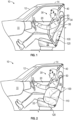
- FIG. 1 is a side view of an interior of a vehicle 10 having a side airbag assembly 100 in a packaged and undeployed state.
- a dashboard (or instrument panel) 11, windscreen 12, roof 14, and door 20 are shown for reference.
- a vehicle seating position 30 is also shown.
- An occupant 50 is shown in the vehicle seating position 30 in a seated and upright position.
- the vehicle seating position 30 shown is a front driver location; however, embodiments of the disclosure herein may be suitable for other vehicle seating positions 30 within the vehicle 10, such as a front passenger seat, and the like.
- the vehicle seating position 30 can include an occupant seat 32, a seat back 34, and a restraint harness 40.
- the side airbag assembly 100 is mounted at an outboard portion of the seat back 34 (proximal to the viewing plane of FIG. 1 ).
- the side airbag assembly 100 may couple at the seat back 34 such that the side airbag assembly 100 may be substantially within the seat back 34 and at a position lateral to the vehicle seating position 30.
- the seat back 34 may comprise a burst seam that bursts open upon deployment of the side airbag assembly 100, and the side airbag assembly 100 deploys through the burst seam.
- an inflatable side airbag cushion 120 may be folded, rolled, and the like in the compressed state.
- FIG. 2 is a side view of the interior of the vehicle 10 having the side airbag assembly 100, with the inflatable side airbag cushion 120 in a deployed state and at least partially inflated, and with the occupant 50 seated in an upright position in the vehicle seating position 30.
- the side airbag assembly 100 may include an inflator 110, the inflatable side airbag cushion 120, a wrapper (not shown, but see, e.g., 130 in FIG. 4 ), and a cap (not shown, but see, e.g., 140 in FIG. 4 ).
- the side airbag assembly 100 may couple at an inboard portion of the seat back 34.
- the inflator 110 may be triggered or activated, which rapidly fills the inflatable side airbag cushion 120 to at least partially inflate the inflatable side airbag cushion 120.
- the inflatable side airbag cushion 120 may deploy from the seat back 34 through the burst seam to a position approximately lateral to the occupant 50.
- the inflatable side airbag cushion 120 deploys to an outboard side of the occupant 50.
- the inflatable side airbag cushion 120 comprises a single chamber.
- the inflatable side airbag cushion 120 may comprise a plurality of chambers.
- the inflatable side airbag cushion 120 may be configured to receive at least a portion of a torso 56 of the occupant 50 as the occupant 50 moves from the vehicle seating position 30.
- a shoulder 54 of the occupant 50 may be above the height of the inflatable side airbag cushion 120.
- a configuration such as that shown in FIG. 2 may be particularly suited to use in a vehicle 10 having an inflatable curtain such that the inflatable side airbag cushion 120 and the inflatable curtain do not interfere with each other, but, rather, augment each other.
- the inflatable side airbag cushion 120 may be suitable for a frontal collisions, oblique collisions, and/or side collisions.
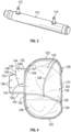
- FIG. 3 illustrates a perspective view of the inflator 110 according to one embodiment of the present disclosure.
- the inflator 110 may be an appropriate airbag inflator for the purpose of inflating the inflatable side airbag cushion 120.
- the inflator 110 can include a gas canister, a chemical container, or other method for generation of inflation gas, and any conduit(s) or ducting (plumbing) for delivering or supplying inflation gas to the inflatable side airbag cushion 120, and other components related to generation and delivery of inflation gas.
- the inflator 110 is in fluid communication with the inflatable side airbag cushion 120.
- the inflator 110 is disposed within the inflatable side airbag cushion 120.
- the inflator is partially disposed within the inflatable side airbag cushion 120.
- the inflator 110 comprises an attachment stud for attaching the inflator 110 to a frame of the seat back 34.
- the inflator 110 comprises a first attachment stud 112 and a second attachment stud 114 that are spaced apart.
- the current disclosure is not so limited, and the inflator 110 may comprise more or less than two attachment studs.
- the attachment studs 112 and 114 are used to attach the side airbag assembly 100 to the frame of the seat back 34 of vehicle seating position 30.
- FIG. 4 illustrates a front view of the inflatable side airbag cushion 120, the wrapper 130, and the cap 140 in an unpackaged configuration.
- FIG. 5 illustrates a rear view of the inflatable side airbag cushion 120, the wrapper 130, and the cap 140 of FIG. 4 in the unpackaged configuration.
- the inflatable side airbag cushion 120 may comprise a substantially oval shape. However, the present disclosure is not so limited and the inflatable side airbag cushion 120 may be circular, triangular, polygonal and/or other shapes.
- the inflatable side airbag cushion 120 may comprise a first lateral end 121, a second lateral end 122, an upper end 123, and a lower end 124.
- One of the lateral ends 121 and 122 may comprise a plurality of apertures 125.
- the plurality of apertures 125 may be spaced apart (e.g., so as to be vertically spaced apart when installed in a vehicle seat) and are configured to receive the plurality of attachment studs 112 and 114 of the inflator 110.
- the number of apertures 125 in the inflatable side airbag cushion 120 may correspond with the number of attachment studs 112 and 114 on the inflator 110.
- the apertures 125 are spaced apart a similar distance as the attachment studs 112 and 114 of the inflator 110 are spaced apart.
- the plurality of apertures 125 are disposed on the second lateral end 122 of the inflatable side airbag cushion 120.
- the plurality of apertures 125 may be disposed on the first lateral end 121 of the inflatable side airbag cushion 120.
- the inflator 110 is disposed within the inflatable side airbag cushion 120. In some embodiments, the inflator 110 is disposed outside the inflatable side airbag cushion 120. In some embodiments, the inflator 110 is partially disposed within and outside the inflatable side airbag cushion 120.
- the inflatable side airbag cushion 120 may be formed from one or more panels 126 of suitable material by means of cutting, folding, bending, turning or otherwise shaping such material, and by application of seams 128 at appropriate locations.
- the seams 128 may be formed by sewing, adhesive, taping, radio frequency (RF) welding, or any other suitable means.
- the seams 128 may be gas impermeable, semipermeable, or permeable, as appropriate.
- the inflatable side airbag cushion 120 may be configured to receive inflation gas from the inflator 110 (not shown) to expand the inflatable side airbag cushion 120 from a packaged state to a deployed state.
- the inflatable side airbag cushion 120 may further comprise a plurality of vents 129 to vent the gas during ride down of the inflatable side airbag cushion 120.
- the inflatable side airbag cushion 120 is configured to collapse into a packaged state. As discussed above, the inflatable side airbag cushion 120 may be folded, rolled, and the like. In one embodiment, the inflatable side airbag cushion 120 may be rolled laterally from the first lateral end 121 toward the second lateral end 122 to form a rolled configuration.
- the wrapper 130 is configured to wrap around the inflatable side airbag cushion 120 and the inflator 110 in the rolled configuration.
- the wrapper 130 comprises a substantially rectangular shape with a first lateral end 131, a second lateral end 132, an upper end 133, and a bottom end 134.
- the first lateral end 131 and the second lateral end 132 may both comprise a plurality of apertures 135 and 136 that are vertically spaced apart.
- the number of apertures 135 on the first lateral end 131 and the number of apertures 136 on the second lateral end 132 correspond with the number of attachment studs 112 and 114 on the inflator 110.
- the apertures 135 and 136 are configured to receive the attachment studs 112 and 114 of the inflator 110.
- the apertures 135 and 136 are vertically spaced apart a similar distance as the attachment studs 112 and 114 of the inflator 110.
- the apertures 135 and 136 may be reinforced by additional material and stitching. As illustrated in FIG. 5 , a reinforcement material 137 is aligned with the plurality of apertures 136 and secured to the wrapper 130 via stitching 139. The reinforcement material 137 and the stitching 139 reinforce the apertures 136 from tearing from the attachment studs 112 and 114 of the inflator 110 before deployment of the inflatable side airbag cushion 120.
- the apertures 135 of the first lateral end 131 of the wrapper 130 are placed on the plurality of attachment studs 112 and 114.
- the wrapper 130 is then wrapped around the inflatable side airbag cushion 120 in the rolled or packaged configuration, and the apertures 136 of the second lateral end 132 are placed on the plurality of attachment studs 112 and 114.
- the inflatable side airbag cushion 120 is held in the rolled or packaged configuration by the wrapper 130 until deployment of the inflatable side airbag cushion 120.
- the wrapper 130 is configured to burst or otherwise break during deployment (and expansion) of the inflatable side airbag cushion 120.
- the wrapper 130 may be formed of a suitable flexible material, such as a ductile fabric material. In some embodiments, the material may comprise a plurality of polymeric fibers.
- the upper end 123 and the lower end 124 of the inflatable side airbag cushion 120 in the rolled configuration may be wrapped by an additional wrapper 138, as illustrated in FIGS. 6 and 7 .
- the additional wrapper 138 may slide over the upper end 133 and another wrapper may slide over the lower end 134.
- only the upper end 133 has the additional wrapper 138 or only the lower end 134 has the additional wrapper 138.
- the additional wrapper 138 is configured to secure the inflatable side airbag cushion 120 in the rolled configuration until deployment.
- the additional wrapper 138 is configured to break during deployment to allow the inflatable side airbag cushion 120 to deploy.
- the additional wrapper 138 is an adhesive that is taped around the upper end 133 and the lower end 134.
- the additional wrapper 138 is configured to break during deployment to allow the inflatable side airbag cushion 120 to deploy.
- the packaged inflatable side airbag cushion 120 comprises the upper end 123 and the lower end 124.
- the cap 140 is configured to enclose one of the ends 123 and 124 of the inflatable side airbag cushion 120. In the illustrated embodiment, the cap 140 encloses the upper end 123.
- the cap 140 may be coupled to the upper end 133 of the wrapper 130. In some embodiments, the cap 140 is integral with the wrapper 130.
- the cap 140 may be formed of a suitable flexible material, such as a ductile fabric material. In some embodiments, the material may comprise a plurality of polymeric fibers.
- the material for the cap 140 and the material for the wrapper 130 may be the same material.
- the cap 140 comprises a single piece or sheet of material that is folded back upon itself along a fold 144 forming a first panel 141 and a second panel 142.
- the first panel 141 is coupled to the upper end 133 of the wrapper 130 in a center portion of the wrapper.
- the second panel 142 may have a greater length (e.g., vertical direction) than the first panel 141.
- the first panel 141 may be coupled to the upper end 133 of the wrapper 130 via stitching, an adhesive, or the like. In some embodiments, the first panel 141 is integral with the wrapper 130.
- the second panel 142 is coupled to one of the plurality of attachment studs 112 and 114 of the inflator 110.
- the second panel 142 may comprise an aperture 143 that is configured to receive one of the attachment studs 112 and 114 of the inflator 110.
- the second panel 142 may comprise a plurality of apertures that are configured to receive a corresponding attachment stud of the plurality of attachment studs 112 and 114 of the inflator 110.
- the number of apertures in the second panel 142 may correspond with the number of attachment studs of the inflator 110.
- the cap 140 may comprise a horizontal stitching seam 146 that extends substantially from a first lateral edge 147 to a second lateral edge 148 of the cap 140.
- the horizontal stitching seam 146 is configured to couple the first panel 141 to the second panel 142.
- the horizontal stitching seam 146 may be disposed a predetermined distance from the fold 144.
- the cap 140 may further comprise a pair of lateral stitching seams 149 that are disposed in the first lateral edge 147 and the second lateral edge 148.
- the lateral stitching seams 149 may extend a majority of the length of the first panel 141.
- the horizontal stitching seam 146 and the lateral stitching seams 149 provide some rigidity to the cap 140 to help prevent the cap 140 from being bent over during the assembly of the seat back 34 of the vehicle seating position 30.
- the cap 140 may have a predetermined amount of stiffness to prevent the upper end of the side airbag assembly 100 from being bent over during the manufacture of the seat back 34.
- the degree of stiffness counters forces on the cap 140 when foam for the seat slides into place on a frame of the seat, discussed below. Thereby preventing an upper end 123 of the side airbag assembly 110 from bending over.
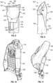
- FIG. 6 illustrates the side airbag assembly 100 in a partially assembled configuration.
- the cap 140 is not pulled over the upper end 123 of the inflatable side airbag cushion 120 in the rolled configuration.
- FIG. 7 illustrates the side airbag assembly 100 in an assembled configuration with the cap 140 encompassing the upper end 123 of the inflatable side airbag cushion 120 in the rolled configuration.
- the aperture 143 of the second panel 142 is placed over the attachment stud 112 of the inflator 110.
- a rigid member 150 may be inserted in between the first panel 141 and the second panel 142 and between the fold 144 and the horizontal stitching seam 146.
- the rigid member 150 may be secured in place by the horizontal stitching seam 146.
- the rigid member 150 is illustrated in phantom lines because it is not visible between the first panel 141 and the second panel 142.
- the rigid member 150 provides rigidity to the cap 140 to help prevent the cap 140 from being bent over during the manufacture of the seat back 34.
- the rigid member 150 may be fabricated from any suitable material that provides enough stiffness to strengthen the cap 140.
- FIG. 8 illustrates a detailed rear view of the side airbag assembly 100 in the assembled configuration with the cap 140 disposed over the upper end 123 of the inflatable side airbag cushion 120.
- FIG. 9 illustrates a detailed side view of the side airbag assembly 100 in the assembled configuration with the cap 140 disposed over the upper end 123 of the inflatable side airbag cushion 120.
- the second panel 142 of the cap may comprise a curve.
- the curve of the second panel 142 may have a radius of curvature R, as illustrated in FIG. 9 .
- the curve may be a compound curve.
- FIG. 10 illustrates the side airbag assembly 100 in the assembled configuration coupled to a frame of the seat back 34 of the vehicle seating position 30. Only a rear view of the side airbag assembly 100 is visible as the front side of the side airbag assembly 100 is coupled to the frame of the seat back 34.
- the side airbag assembly 100 is coupled to the frame via the attachment studs 112 and 114 of the inflator 110 (not shown in FIG. 10 ).
- FIG. 11 illustrates the foam pad 36 attached to the seat back 34.
- the cap 140 is designed to prevent the inflatable side airbag cushion 120 from being bent over when the foam pad 36 is slid into place on the frame of the seat back 34. This is accomplished through a number of different features of the side airbag assembly 100. For example, the stiffness of the cap 140 prevents the inflatable side airbag cushion 120 from being bent over. In addition, the radius of curvature R of the cap 140 guides the foam pad 36 into place on the frame.
- Coupled to and “in communication with” refer to any form of interaction between two or more entities, including mechanical, electrical, magnetic, electromagnetic, fluid, and thermal interaction. Two components may be coupled to each other even though they are not in direct contact with each other.
- a and “an” can be described as one, but not limited to one.
- the disclosure may recite an airbag having "a chamber,” the disclosure also contemplates that the airbag can have two or more chambers.
- the terms “forward” and “rearward” are used with reference to the front and back of the relevant vehicle.
- an airbag cushion that deploys in a rearward direction deploys toward the back of a vehicle.
- other reference terms, such as “horizontal,” are used relative to a vehicle in which an airbag assembly is installed, unless it is clear from context that a different reference frame is intended.
- a term such as “horizontal” is used relative to the vehicle, whether or not the vehicle itself is oriented horizontally (e.g., is positioned upright on level ground) or angled relative to true horizontal (e.g., is positioned on a hill).
- vehicle seating position refers to a position in which an occupant is generally positioned when seated in a seat of a vehicle.
- occupant refers to a person or crash test dummy within a vehicle.
Landscapes
- Engineering & Computer Science (AREA)
- Mechanical Engineering (AREA)
- Air Bags (AREA)
Description
- The present disclosure relates generally to the field of automotive protective systems. More specifically, the present disclosure relates to side airbag systems that are configured to deploy in response to collision events.
-
DE102006031117A1 andJP2015074295A - The present embodiments will become more fully apparent from the following description and appended claims, taken in conjunction with the accompanying drawings. Understanding that the accompanying drawings depict only typical embodiments, and are, therefore, not to be considered limiting of the scope of the disclosure, the embodiments will be described and explained with specificity and detail in reference to the accompanying drawings.
-
FIG. 1 is a side view of an interior of a vehicle having a side airbag assembly, according to one embodiment of the present disclosure, in a packaged and undeployed state. -
FIG. 2 is a side view of the airbag assembly ofFIG. 1 in a deployed state during a vehicle impact event. -
FIG. 3 is a perspective view of an inflator of a side airbag assembly according to one embodiment of the present disclosure. -
FIG. 4 is a rear view of an airbag assembly in an unassembled configuration, according to one embodiment of the present disclosure. -
FIG. 5 is a front view of the airbag assembly ofFIG. 4 in an unassembled configuration. -
FIG. 6 is a perspective view of an airbag assembly in a rolled or packaged configuration with a cap not yet enclosing an end of the airbag assembly according to one embodiment of the present disclosure. -
FIG. 7 is a perspective view of the airbag assembly ofFIG. 6 with the cap enclosing the end of the airbag assembly. -
FIG. 8 is a detailed rear view of the airbag assembly in a packaged configuration ofFIG. 7 . -
FIG. 9 is a detailed side view of the airbag assembly ofFIG. 7 . -
FIG. 10 is a perspective view of an airbag assembly coupled to a frame of a seat of a vehicle, according to one embodiment of the present disclosure. -
FIG. 11 is a perspective view of the airbag assembly ofFIG. 10 - An airbag assembly according to an aspect of the present invention is set forth in
claim 1. A method of packaging a side airbag assembly according to a second aspect of the invention is set forth inclaim 14. - It will be readily understood that the components of the embodiments as generally described and illustrated in the figures herein could be arranged and designed in a wide variety of different configurations. Thus, the following more detailed description of various embodiments, as represented in the figures, is not intended to limit the scope of the disclosure, as claimed, but is merely representative of various embodiments. While the various aspects of the embodiments are presented in drawings, the drawings are not necessarily drawn to scale unless specifically indicated.
- Inflatable airbag assemblies are widely used to reduce or minimize occupant injury during a collision event. Airbag modules have been installed at various locations within a vehicle, including, but not limited to, in the steering wheel, in the dashboard and/or instrument panel, within the side doors or side seats, adjacent to a roof rail of the vehicle, in an overhead position, or at the knee or leg position. The disclosed airbag assemblies and airbag embodiments may be utilized in place of or in conjunction with other airbags, such as, for example, a front passenger airbag that is typically housed within the dashboard, driver airbags housed within the steering wheel, knee airbags, and side airbags. Further, the disclosed airbag assemblies may be used in an autonomous vehicle (e.g., in a vehicle that may not have a steering wheel and/or that may have limited, or no, reaction surface such as an instrument panel).
- As used herein, the terms "dashboard" and "instrument panel" refer to a protruding region of a vehicle faced by a motor vehicle occupant, which often includes a glove compartment in a portion thereof that faces a passenger and may include instruments (e.g., radio and/or climate controls) in a more central region thereof, although such instruments need not be present.
- The term "opposite" is a relational term used herein to refer to a placement of a particular feature or component in a position corresponding to another related feature or component wherein the corresponding features or components are positionally juxtaposed to each other. By way of example, a person's right hand is opposite the person's left hand. An inboard component may be situated opposite an outboard component.
- Throughout this specification, the phrases "coupled to" and "in communication with" refer to any form of interaction between two or more entities, including mechanical, electrical, magnetic, electromagnetic, fluid, and thermal interaction. Two components may be coupled to each other even though they are not in direct contact with each other.
- As used herein, "inboard" refers to a direction toward a centerline of a vehicle, and "outboard" refers to a direction out of the vehicle and away from a centerline of the vehicle.
- The phrase "ride down" as used in this disclosure bears the ordinary meaning of the words relative to inflatable airbag systems. That is, "ride down" typically involves an occupant in contact with an inflatable airbag cushion for some period of time during which the inflatable airbag cushion may support and nominally protect to some degree the occupant from impact(s) with some structure(s)/component(s) of a vehicle, and during which the inflatable airbag cushion may partially deflate to ameliorate deceleration forces.
- The phrase "fluid communication" is used in its ordinary sense, and is broad enough to refer to arrangements in which a fluid (e.g., a gas or a liquid) can flow from one element to another element when the elements are in fluid communication with each other.
- The terms "longitudinal" and "longitudinally" refer to a direction or orientation extending or spanning between a front of a vehicle and a rear of the vehicle.
- During installation, the disclosed airbags are typically in a packaged state (e.g., are rolled, folded, and/or otherwise compressed) or a compact configuration and may be retained in the packaged state by a wrapper. During a collision event, an inflator is triggered, which rapidly fills the airbag with inflation gas. The airbag can rapidly transition from a packaged state (e.g., a compact configuration) to a deployed state or an expanded configuration. For example, the expanding airbag can tear open the wrapper. The inflator may be triggered by any suitable device or system, and the triggering may be in response to and/or influenced by one or more vehicle sensors.
-
FIG. 1 is a side view of an interior of avehicle 10 having aside airbag assembly 100 in a packaged and undeployed state. A dashboard (or instrument panel) 11,windscreen 12,roof 14, anddoor 20 are shown for reference. Avehicle seating position 30 is also shown. Anoccupant 50 is shown in thevehicle seating position 30 in a seated and upright position. InFIG. 1 , thevehicle seating position 30 shown is a front driver location; however, embodiments of the disclosure herein may be suitable for othervehicle seating positions 30 within thevehicle 10, such as a front passenger seat, and the like. Thevehicle seating position 30 can include anoccupant seat 32, aseat back 34, and arestraint harness 40. Theside airbag assembly 100 is mounted at an outboard portion of the seat back 34 (proximal to the viewing plane ofFIG. 1 ). - The
side airbag assembly 100 may couple at theseat back 34 such that theside airbag assembly 100 may be substantially within theseat back 34 and at a position lateral to thevehicle seating position 30. Theseat back 34 may comprise a burst seam that bursts open upon deployment of theside airbag assembly 100, and theside airbag assembly 100 deploys through the burst seam. In some embodiments, an inflatableside airbag cushion 120 may be folded, rolled, and the like in the compressed state. -
FIG. 2 is a side view of the interior of thevehicle 10 having theside airbag assembly 100, with the inflatableside airbag cushion 120 in a deployed state and at least partially inflated, and with theoccupant 50 seated in an upright position in thevehicle seating position 30. Theside airbag assembly 100 may include aninflator 110, the inflatableside airbag cushion 120, a wrapper (not shown, but see, e.g., 130 inFIG. 4 ), and a cap (not shown, but see, e.g., 140 inFIG. 4 ). In some embodiments, theside airbag assembly 100 may couple at an inboard portion of theseat back 34. - During a collision event, the
inflator 110 may be triggered or activated, which rapidly fills the inflatableside airbag cushion 120 to at least partially inflate the inflatableside airbag cushion 120. The inflatableside airbag cushion 120 may deploy from the seat back 34 through the burst seam to a position approximately lateral to theoccupant 50. In some embodiments, the inflatableside airbag cushion 120 deploys to an outboard side of theoccupant 50. In the illustrated embodiment ofFIG. 2 , the inflatableside airbag cushion 120 comprises a single chamber. However, the present disclosure is not so limited. The inflatableside airbag cushion 120 may comprise a plurality of chambers. - With the inflatable
side airbag cushion 120 deployed, the inflatableside airbag cushion 120 may be configured to receive at least a portion of atorso 56 of theoccupant 50 as theoccupant 50 moves from thevehicle seating position 30. In the embodiment ofFIG. 2 , ashoulder 54 of theoccupant 50 may be above the height of the inflatableside airbag cushion 120. A configuration such as that shown inFIG. 2 may be particularly suited to use in avehicle 10 having an inflatable curtain such that the inflatableside airbag cushion 120 and the inflatable curtain do not interfere with each other, but, rather, augment each other. The inflatableside airbag cushion 120 may be suitable for a frontal collisions, oblique collisions, and/or side collisions. -
FIG. 3 illustrates a perspective view of the inflator 110 according to one embodiment of the present disclosure. The inflator 110 may be an appropriate airbag inflator for the purpose of inflating the inflatableside airbag cushion 120. The inflator 110 can include a gas canister, a chemical container, or other method for generation of inflation gas, and any conduit(s) or ducting (plumbing) for delivering or supplying inflation gas to the inflatableside airbag cushion 120, and other components related to generation and delivery of inflation gas. In other words, theinflator 110 is in fluid communication with the inflatableside airbag cushion 120. In some embodiments, theinflator 110 is disposed within the inflatableside airbag cushion 120. In some embodiments, the inflator is partially disposed within the inflatableside airbag cushion 120. - The
inflator 110 comprises an attachment stud for attaching the inflator 110 to a frame of the seat back 34. In the illustrated embodiment ofFIG. 3 , theinflator 110 comprises afirst attachment stud 112 and asecond attachment stud 114 that are spaced apart. However, the current disclosure is not so limited, and the inflator 110 may comprise more or less than two attachment studs. Theattachment studs side airbag assembly 100 to the frame of the seat back 34 ofvehicle seating position 30. -
FIG. 4 illustrates a front view of the inflatableside airbag cushion 120, thewrapper 130, and thecap 140 in an unpackaged configuration.FIG. 5 illustrates a rear view of the inflatableside airbag cushion 120, thewrapper 130, and thecap 140 ofFIG. 4 in the unpackaged configuration. - The inflatable
side airbag cushion 120 may comprise a substantially oval shape. However, the present disclosure is not so limited and the inflatableside airbag cushion 120 may be circular, triangular, polygonal and/or other shapes. The inflatableside airbag cushion 120 may comprise a firstlateral end 121, a secondlateral end 122, anupper end 123, and alower end 124. One of the lateral ends 121 and 122 may comprise a plurality ofapertures 125. The plurality ofapertures 125 may be spaced apart (e.g., so as to be vertically spaced apart when installed in a vehicle seat) and are configured to receive the plurality ofattachment studs inflator 110. The number ofapertures 125 in the inflatableside airbag cushion 120 may correspond with the number ofattachment studs inflator 110. Theapertures 125 are spaced apart a similar distance as theattachment studs apertures 125 are disposed on the secondlateral end 122 of the inflatableside airbag cushion 120. Alternatively, the plurality ofapertures 125 may be disposed on the firstlateral end 121 of the inflatableside airbag cushion 120. - In some embodiments, the
inflator 110 is disposed within the inflatableside airbag cushion 120. In some embodiments, theinflator 110 is disposed outside the inflatableside airbag cushion 120. In some embodiments, theinflator 110 is partially disposed within and outside the inflatableside airbag cushion 120. - The inflatable
side airbag cushion 120 may be formed from one ormore panels 126 of suitable material by means of cutting, folding, bending, turning or otherwise shaping such material, and by application ofseams 128 at appropriate locations. Theseams 128 may be formed by sewing, adhesive, taping, radio frequency (RF) welding, or any other suitable means. Theseams 128 may be gas impermeable, semipermeable, or permeable, as appropriate. The inflatableside airbag cushion 120 may be configured to receive inflation gas from the inflator 110 (not shown) to expand the inflatableside airbag cushion 120 from a packaged state to a deployed state. The inflatableside airbag cushion 120 may further comprise a plurality ofvents 129 to vent the gas during ride down of the inflatableside airbag cushion 120. - The inflatable
side airbag cushion 120 is configured to collapse into a packaged state. As discussed above, the inflatableside airbag cushion 120 may be folded, rolled, and the like. In one embodiment, the inflatableside airbag cushion 120 may be rolled laterally from the firstlateral end 121 toward the secondlateral end 122 to form a rolled configuration. - The
wrapper 130 is configured to wrap around the inflatableside airbag cushion 120 and the inflator 110 in the rolled configuration. In some embodiments, thewrapper 130 comprises a substantially rectangular shape with a firstlateral end 131, a secondlateral end 132, anupper end 133, and abottom end 134. The firstlateral end 131 and the secondlateral end 132 may both comprise a plurality ofapertures apertures 135 on the firstlateral end 131 and the number ofapertures 136 on the secondlateral end 132 correspond with the number ofattachment studs inflator 110. Theapertures attachment studs inflator 110. Theapertures attachment studs inflator 110. - In some embodiments, the
apertures FIG. 5 , areinforcement material 137 is aligned with the plurality ofapertures 136 and secured to thewrapper 130 viastitching 139. Thereinforcement material 137 and thestitching 139 reinforce theapertures 136 from tearing from theattachment studs side airbag cushion 120. - To wrap the inflatable
side airbag cushion 120, theapertures 135 of the firstlateral end 131 of thewrapper 130 are placed on the plurality ofattachment studs wrapper 130 is then wrapped around the inflatableside airbag cushion 120 in the rolled or packaged configuration, and theapertures 136 of the secondlateral end 132 are placed on the plurality ofattachment studs side airbag cushion 120 is held in the rolled or packaged configuration by thewrapper 130 until deployment of the inflatableside airbag cushion 120. Thewrapper 130 is configured to burst or otherwise break during deployment (and expansion) of the inflatableside airbag cushion 120. Thewrapper 130 may be formed of a suitable flexible material, such as a ductile fabric material. In some embodiments, the material may comprise a plurality of polymeric fibers. - In some embodiments, the
upper end 123 and thelower end 124 of the inflatableside airbag cushion 120 in the rolled configuration may be wrapped by anadditional wrapper 138, as illustrated inFIGS. 6 and 7 . Theadditional wrapper 138 may slide over theupper end 133 and another wrapper may slide over thelower end 134. In some embodiments, only theupper end 133 has theadditional wrapper 138 or only thelower end 134 has theadditional wrapper 138. Theadditional wrapper 138 is configured to secure the inflatableside airbag cushion 120 in the rolled configuration until deployment. Theadditional wrapper 138 is configured to break during deployment to allow the inflatableside airbag cushion 120 to deploy. - In some embodiments the
additional wrapper 138 is an adhesive that is taped around theupper end 133 and thelower end 134. Theadditional wrapper 138 is configured to break during deployment to allow the inflatableside airbag cushion 120 to deploy. - In the packaged configuration, the packaged inflatable
side airbag cushion 120 comprises theupper end 123 and thelower end 124. Thecap 140 is configured to enclose one of theends side airbag cushion 120. In the illustrated embodiment, thecap 140 encloses theupper end 123. Thecap 140 may be coupled to theupper end 133 of thewrapper 130. In some embodiments, thecap 140 is integral with thewrapper 130. Thecap 140 may be formed of a suitable flexible material, such as a ductile fabric material. In some embodiments, the material may comprise a plurality of polymeric fibers. The material for thecap 140 and the material for thewrapper 130 may be the same material. - The
cap 140 comprises a single piece or sheet of material that is folded back upon itself along afold 144 forming afirst panel 141 and asecond panel 142. Thefirst panel 141 is coupled to theupper end 133 of thewrapper 130 in a center portion of the wrapper. Thesecond panel 142 may have a greater length (e.g., vertical direction) than thefirst panel 141. - The
first panel 141 may be coupled to theupper end 133 of thewrapper 130 via stitching, an adhesive, or the like. In some embodiments, thefirst panel 141 is integral with thewrapper 130. Thesecond panel 142 is coupled to one of the plurality ofattachment studs inflator 110. For example, thesecond panel 142 may comprise anaperture 143 that is configured to receive one of theattachment studs inflator 110. In some embodiments, thesecond panel 142 may comprise a plurality of apertures that are configured to receive a corresponding attachment stud of the plurality ofattachment studs inflator 110. The number of apertures in thesecond panel 142 may correspond with the number of attachment studs of theinflator 110. - The
cap 140 may comprise ahorizontal stitching seam 146 that extends substantially from a firstlateral edge 147 to a secondlateral edge 148 of thecap 140. Thehorizontal stitching seam 146 is configured to couple thefirst panel 141 to thesecond panel 142. Thehorizontal stitching seam 146 may be disposed a predetermined distance from thefold 144. - The
cap 140 may further comprise a pair of lateral stitching seams 149 that are disposed in the firstlateral edge 147 and the secondlateral edge 148. The lateral stitching seams 149 may extend a majority of the length of thefirst panel 141. - The
horizontal stitching seam 146 and the lateral stitching seams 149 provide some rigidity to thecap 140 to help prevent thecap 140 from being bent over during the assembly of the seat back 34 of thevehicle seating position 30. For example, thecap 140 may have a predetermined amount of stiffness to prevent the upper end of theside airbag assembly 100 from being bent over during the manufacture of the seat back 34. The degree of stiffness counters forces on thecap 140 when foam for the seat slides into place on a frame of the seat, discussed below. Thereby preventing anupper end 123 of theside airbag assembly 110 from bending over. -
FIG. 6 illustrates theside airbag assembly 100 in a partially assembled configuration. Thecap 140 is not pulled over theupper end 123 of the inflatableside airbag cushion 120 in the rolled configuration.FIG. 7 illustrates theside airbag assembly 100 in an assembled configuration with thecap 140 encompassing theupper end 123 of the inflatableside airbag cushion 120 in the rolled configuration. Theaperture 143 of thesecond panel 142 is placed over theattachment stud 112 of theinflator 110. - In some embodiments, a
rigid member 150 may be inserted in between thefirst panel 141 and thesecond panel 142 and between thefold 144 and thehorizontal stitching seam 146. Therigid member 150 may be secured in place by thehorizontal stitching seam 146. Therigid member 150 is illustrated in phantom lines because it is not visible between thefirst panel 141 and thesecond panel 142. Therigid member 150 provides rigidity to thecap 140 to help prevent thecap 140 from being bent over during the manufacture of the seat back 34. Therigid member 150 may be fabricated from any suitable material that provides enough stiffness to strengthen thecap 140. -
FIG. 8 illustrates a detailed rear view of theside airbag assembly 100 in the assembled configuration with thecap 140 disposed over theupper end 123 of the inflatableside airbag cushion 120.FIG. 9 illustrates a detailed side view of theside airbag assembly 100 in the assembled configuration with thecap 140 disposed over theupper end 123 of the inflatableside airbag cushion 120. Thesecond panel 142 of the cap may comprise a curve. The curve of thesecond panel 142 may have a radius of curvature R, as illustrated inFIG. 9 . In some embodiments, the curve may be a compound curve. -
FIG. 10 illustrates theside airbag assembly 100 in the assembled configuration coupled to a frame of the seat back 34 of thevehicle seating position 30. Only a rear view of theside airbag assembly 100 is visible as the front side of theside airbag assembly 100 is coupled to the frame of the seat back 34. Theside airbag assembly 100 is coupled to the frame via theattachment studs FIG. 10 ). - After the
side airbag assembly 100 is attached to the frame of the seat back 34, afoam pad 36 may be attached to the seat back 34.FIG. 11 illustrates thefoam pad 36 attached to the seat back 34. During installation, thefoam pad 36 is typically slid over the frame of the seat back 34. Thecap 140 is designed to prevent the inflatableside airbag cushion 120 from being bent over when thefoam pad 36 is slid into place on the frame of the seat back 34. This is accomplished through a number of different features of theside airbag assembly 100. For example, the stiffness of thecap 140 prevents the inflatableside airbag cushion 120 from being bent over. In addition, the radius of curvature R of thecap 140 guides thefoam pad 36 into place on the frame. - Throughout this specification, the phrases "coupled to" and "in communication with" refer to any form of interaction between two or more entities, including mechanical, electrical, magnetic, electromagnetic, fluid, and thermal interaction. Two components may be coupled to each other even though they are not in direct contact with each other.
- The terms "a" and "an" can be described as one, but not limited to one. For example, although the disclosure may recite an airbag having "a chamber," the disclosure also contemplates that the airbag can have two or more chambers.
- As used herein, the terms "forward" and "rearward" are used with reference to the front and back of the relevant vehicle. For example, an airbag cushion that deploys in a rearward direction deploys toward the back of a vehicle. Furthermore, other reference terms, such as "horizontal," are used relative to a vehicle in which an airbag assembly is installed, unless it is clear from context that a different reference frame is intended. Thus, a term such as "horizontal" is used relative to the vehicle, whether or not the vehicle itself is oriented horizontally (e.g., is positioned upright on level ground) or angled relative to true horizontal (e.g., is positioned on a hill).
- Unless otherwise stated, all ranges include both endpoints and all numbers between the endpoints.
- The phrase "vehicle seating position" refers to a position in which an occupant is generally positioned when seated in a seat of a vehicle. The term "occupant" refers to a person or crash test dummy within a vehicle.
- Reference throughout this specification to "an embodiment" or "the embodiment" means that a particular feature, structure, or characteristic described in connection with that embodiment is included in at least one embodiment. Thus, the quoted phrases, or variations thereof, as recited throughout this specification are not necessarily all referring to the same embodiment.
- Similarly, it should be appreciated that in the above description of embodiments, various features are sometimes grouped together in a single embodiment, figure, or description thereof for the purpose of streamlining the disclosure. This method of disclosure, however, is not to be interpreted as reflecting an intention that any claim require more features than those expressly recited in that claim. Rather, as the following claims reflect, inventive aspects lie in a combination of fewer than all features of any single foregoing disclosed embodiment.
- Recitation in the claims of the term "first" with respect to a feature or element does not necessarily imply the existence of a second or additional such feature or element. It will be apparent to those having reasonable skill in the art that changes may be made to the details of the above-described embodiments without departing from the scope of the invention as defined by the appended claims.
Claims (17)
- An airbag assembly (100) in a packaged state comprising:an inflatable airbag cushion (120) in a packaged configuration;an inflator (110) in fluid communication with the inflatable airbag cushion (120) to supply inflation gas to inflate the inflatable airbag cushion (120), the inflator (110) comprising an attachment stud (112, 114) to mount the airbag assembly (100) to a side of a seat;a wrapper (130) configured to wrap around the inflator (110) and the inflatable airbag cushion (120) in the packaged configuration;a cap (140) coupled to the wrapper, wherein the cap is configured to enclose a first end (133) of the inflatable airbag cushion (120) in the packaged configuration to increase stiffness at the first end (133); andcharacterised bythe cap (140) comprising a single sheet of material that is folded back upon itself along a fold forming a first panel (141) and a second panel (142), wherein the first panel (141) of the cap (140) is coupled at a center portion of the wrapper (130) and the second panel of the cap is coupled to the attachment stud (112, 114) of the inflator.
- The airbag assembly (100) of claim 1, wherein the wrapper (130) comprises a substantially rectangular shape to wrap around the inflatable airbag cushion (120) in the packaged configuration, the rectangular shape including a first lateral end (131) and a second lateral end (132), the first lateral end (131) including a first aperture (135) to secure the first lateral end (131) at the attachment stud (112, 114) and the second lateral end (132) including a second aperture (136) to secure the second lateral end (132) at the attachment stud (112, 114).
- The airbag assembly (100) of claim 1, wherein the inflator (110) comprises a plurality of attachment studs (112, 114) that are spaced apart, and
wherein the wrapper (130) comprises a substantially rectangular shape, the wrapper (130) comprises a first lateral end (131) and a second lateral end (132) each including one or more apertures of a plurality of apertures (135, 136) spaced apart, wherein each aperture of the one or more apertures is configured to receive one of the plurality of attachment studs (112, 114) of the inflator (110). - The airbag assembly (100) of claim 1, wherein the cap (140) comprises a predetermined amount of stiffness to prevent an upper portion of the airbag assembly (100) from bending over when a foam pad (36) for the seat slides into place on a frame of the seat.
- The airbag assembly (100) of claim 1, wherein the cap (140) is formed to provide a degree of stiffness to counter forces on the cap (140), and thereby prevent an upper portion of the airbag assembly (100) from bending over, when a foam pad (36) for the seat slides into place on a frame of the seat.
- The airbag assembly (100) of claim 1, wherein the second panel (142) comprises an aperture (143) that is configured to receive the attachment stud (112, 114) of the inflator (110).
- The airbag assembly (100) of claim 1, wherein the cap (140) comprises a horizontal stitching seam (146) that extends substantially from a first lateral edge (147) of the cap (140) to a second lateral edge (148) of the cap (140).
- The airbag assembly (100) of claim 7, wherein the horizontal stitching seam is disposed a predetermined distance from the fold.
- The airbag assembly (100) of claim 1, wherein the cap (140) comprises a pair of lateral stitching seams (149) that extend along a first lateral edge of the cap (140) and a second lateral edge of the cap (140), wherein the pair of lateral stitching seams couple the first panel (141) to the second panel (142) of the cap (140).
- The airbag assembly (100) of claim 1, wherein the second panel (142) has a greater length than the first panel (141).
- The airbag assembly (100) of claim 1, wherein the first panel (141) of the cap (140) comprises a radius of curvature that is configured to guide foam for the seat when the foam is slid into place on a frame of the seat without bending an upper portion of the airbag assembly (100).
- The airbag assembly (100) of claim 1, wherein the wrapper (130) and the cap (140) are fabricated from a flexible material.
- The airbag assembly (100) of claim 1, wherein the inflator (110) comprises two attachment studs (112, 114) that are vertically spaced apart.
- A method of packaging a side airbag assembly (100) comprising:obtaining an inflatable side airbag cushion (120) with an inflator (110) coupled to and in fluid communication with the inflatable side airbag cushion (120), the inflator (110) comprising an attachment stud (112, 114) to mount the airbag assembly (100) to a side of a seat;rolling the inflatable side airbag cushion (120);wrapping the inflator (110) and the rolled inflatable side airbag cushion (120) with a wrapper (130);enclosing a first end (133) of the rolled inflatable side airbag cushion (120) with a cap (140), wherein the cap (140) comprises a predetermined amount of stiffness to prevent an upper portion of the rolled inflatable side airbag cushion (120) from bending over when foam for a seat is slid into place on a frame of the seat; andcharacterised bythe cap (140) comprising a single sheet of material that is folded back upon itself along a fold forming a first panel (141) and a second panel (142), wherein the first panel (141) of the cap (140) is coupled to a center portion of the wrapper (130) and the second panel (142) of the cap (140) comprises an aperture (143) that is configured to receive the attachment stud (112, 114) of the inflator (110);
- The method of claim 14, wherein the inflator (110) comprises two attachment studs (112, 114) to mount the side airbag assembly (100) to a side of a seat of a vehicle, wherein the two attachment studs (112, 114) are vertically spaced apart.
- The method of claim 15, wherein the wrapper (130) comprises a substantially rectangular shape, the wrapper (130) comprises a first lateral end (131) and a second lateral end (132) with two apertures (135, 136) disposed in the first lateral end (131) and the second lateral end (132) with the apertures vertically spaced apart, wherein each aperture (135, 136) in each end (131, 132) is configured to receive one of the two attachment studs (112, 114) of the inflator (110).
- The method of claim 14, further comprising mounting the side airbag assembly (100) to a side of a seat of a vehicle.
Applications Claiming Priority (1)
| Application Number | Priority Date | Filing Date | Title |
|---|---|---|---|
| US17/231,827 US11299120B1 (en) | 2021-04-15 | 2021-04-15 | Side airbag assemblies and methods of assembly |
Publications (2)
| Publication Number | Publication Date |
|---|---|
| EP4079582A1 EP4079582A1 (en) | 2022-10-26 |
| EP4079582B1 true EP4079582B1 (en) | 2023-12-06 |
Family
ID=81123769
Family Applications (1)
| Application Number | Title | Priority Date | Filing Date |
|---|---|---|---|
| EP22166270.3A Active EP4079582B1 (en) | 2021-04-15 | 2022-04-01 | Side airbag assemblies and methods of assembly |
Country Status (5)
| Country | Link |
|---|---|
| US (1) | US11299120B1 (en) |
| EP (1) | EP4079582B1 (en) |
| JP (1) | JP7333441B2 (en) |
| KR (1) | KR20220142931A (en) |
| CN (1) | CN115214519B (en) |
Families Citing this family (2)
| Publication number | Priority date | Publication date | Assignee | Title |
|---|---|---|---|---|
| USD1020601S1 (en) * | 2020-11-30 | 2024-04-02 | Zoox, Inc. | Vehicle airbag system |
| US11518338B1 (en) * | 2022-01-13 | 2022-12-06 | Autoliv Asp, Inc. | Automotive airbag systems with a securement wrapper and a packaging wrapper |
Family Cites Families (33)
| Publication number | Priority date | Publication date | Assignee | Title |
|---|---|---|---|---|
| JP2785673B2 (en) * | 1994-01-31 | 1998-08-13 | 池田物産株式会社 | Airbag cover of airbag device and method of mounting airbag cover |
| DE9408908U1 (en) * | 1994-05-31 | 1994-11-17 | Trw Repa Gmbh | Airbag protection device |
| US5556128A (en) * | 1994-11-24 | 1996-09-17 | Volkswagen Ag | Safety arrangement for a vehicle occupant |
| JPH08282418A (en) * | 1995-04-07 | 1996-10-29 | Nippon Seiko Kk | Air bag device |
| DE50205481D1 (en) * | 2002-01-04 | 2006-02-02 | Takata Petri Gmbh Ulm | GASSTROM DISTRIBUTOR FOR A SIDE AIRBAG MODULE |
| US20030168836A1 (en) * | 2002-03-11 | 2003-09-11 | Eiji Sato | Side airbag apparatus |
| DE10235128A1 (en) * | 2002-08-01 | 2004-02-19 | Autoliv Development Ab | Joint airbag system for two passengers has two separate gas bags sealed from each other by deflectors and folded into common housing set in dashboard and connected to common gas generator |
| JP4793924B2 (en) * | 2006-06-12 | 2011-10-12 | タカタ株式会社 | Side impact airbag, side impact airbag device, vehicle seat |
| JP5199604B2 (en) * | 2006-06-12 | 2013-05-15 | タカタ株式会社 | Side airbag device, vehicle seat, inflator gas distributor |
| DE102006031117B4 (en) * | 2006-07-05 | 2017-07-06 | Lear Corp. | Method for assembling an airbag assembly and airbag assembly |
| JP2009040229A (en) * | 2007-08-09 | 2009-02-26 | Takata Corp | Airbag device for side impact |
| JP4546515B2 (en) * | 2007-11-27 | 2010-09-15 | 本田技研工業株式会社 | Airbag device for vehicle |
| JP5125596B2 (en) * | 2008-02-22 | 2013-01-23 | 豊田合成株式会社 | Side airbag device |
| DE102008019730A1 (en) * | 2008-03-04 | 2009-09-10 | Takata-Petri Ag | Airbag cover for receiving a gas bag package for an airbag module of a motor vehicle and method for its production |
| DE102009036800A1 (en) * | 2008-08-12 | 2010-02-18 | Dalphimetal España S.A. | Airbag module with gas distribution element |
| JP5163476B2 (en) * | 2008-10-14 | 2013-03-13 | 豊田合成株式会社 | Side airbag device |
| US8408582B2 (en) * | 2010-06-23 | 2013-04-02 | Autoliv Asp, Inc. | Inflatable airbag assemblies with heat shields |
| DE102010039902A1 (en) * | 2010-08-27 | 2012-03-01 | Takata-Petri Ag | Devices for personal protection systems of a vehicle |
| JP5692190B2 (en) * | 2012-09-04 | 2015-04-01 | トヨタ自動車株式会社 | Side airbag device for vehicle and method for manufacturing side airbag |
| JP5692197B2 (en) * | 2012-10-10 | 2015-04-01 | トヨタ自動車株式会社 | Vehicle seat provided with side airbag device and method for assembling side airbag device to vehicle seat |
| JP6070217B2 (en) * | 2013-01-25 | 2017-02-01 | 豊田合成株式会社 | Side airbag device |
| KR102064002B1 (en) * | 2013-05-07 | 2020-01-08 | 현대모비스 주식회사 | The side air bag for a vehicle |
| JP5923059B2 (en) | 2013-05-21 | 2016-05-24 | オートリブ ディベロップメント エービー | Method for manufacturing side airbag device |
| JP5960667B2 (en) * | 2013-10-07 | 2016-08-02 | オートリブ ディベロップメント エービー | Airbag device |
| US9108589B2 (en) * | 2013-11-02 | 2015-08-18 | Autoliv Asp, Inc. | Protective flap for airbags |
| JP6149849B2 (en) * | 2014-11-25 | 2017-06-21 | トヨタ自動車株式会社 | Far-side airbag device for vehicles |
| KR101941256B1 (en) * | 2015-04-13 | 2019-01-22 | 오토리브 디벨로프먼트 에이비 | Curtain airbag device |
| JP6799909B2 (en) | 2015-11-11 | 2020-12-16 | Joyson Safety Systems Japan株式会社 | Airbag device |
| CN110325405B (en) | 2017-02-27 | 2021-12-24 | 奥托立夫开发公司 | Side airbag device |
| JP6801621B2 (en) * | 2017-09-28 | 2020-12-16 | 豊田合成株式会社 | Side airbag device |
| US10994687B2 (en) * | 2018-12-11 | 2021-05-04 | Autoliv Asp, Inc. | Airbag compression wrappers and related airbag assemblies |
| CN210212319U (en) | 2019-07-12 | 2020-03-31 | 延锋汽车智能安全系统(常熟)有限公司 | Seat side airbag device and heat insulating member therefor |
| US11292414B2 (en) * | 2020-07-07 | 2022-04-05 | ZF Passive Safety Systems US Inc. | Airbag packaging wrap |
-
2021
- 2021-04-15 US US17/231,827 patent/US11299120B1/en active Active
-
2022
- 2022-03-21 CN CN202210275473.7A patent/CN115214519B/en active Active
- 2022-04-01 EP EP22166270.3A patent/EP4079582B1/en active Active
- 2022-04-04 JP JP2022062387A patent/JP7333441B2/en active Active
- 2022-04-07 KR KR1020220043360A patent/KR20220142931A/en not_active Application Discontinuation
Also Published As
| Publication number | Publication date |
|---|---|
| CN115214519B (en) | 2023-10-27 |
| JP7333441B2 (en) | 2023-08-24 |
| KR20220142931A (en) | 2022-10-24 |
| EP4079582A1 (en) | 2022-10-26 |
| JP2022164591A (en) | 2022-10-27 |
| US11299120B1 (en) | 2022-04-12 |
| CN115214519A (en) | 2022-10-21 |
Similar Documents
| Publication | Publication Date | Title |
|---|---|---|
| US10583799B2 (en) | Overhead inflatable airbag assembly | |
| US10703325B2 (en) | Multi-chambered side airbag assemblies | |
| JP6681893B2 (en) | Airbag module | |
| CN109311444B (en) | Center side airbag module | |
| US8371612B2 (en) | Inflatable airbag assemblies with lateral and longitudinal tethers | |
| JP6131935B2 (en) | Far-side airbag device for vehicles | |
| EP2496446B1 (en) | Vehicle with a low-mount inflatable knee airbag having serial chambers | |
| US11833990B2 (en) | Side airbag device, vehicle seat provided with same, and method for manufacturing side airbag device | |
| EP2475555B1 (en) | Mounting assemblies with wrappers for inflatable curtain airbags | |
| US7823922B2 (en) | Tether systems for inflatable cushions | |
| KR101391439B1 (en) | Inflatable airbag assembly with an inflator bracket | |
| EP4079582B1 (en) | Side airbag assemblies and methods of assembly | |
| US20160311393A1 (en) | Frontal airbag assemblies | |
| US8814204B2 (en) | Automobile seat in which side airbag device is installed | |
| US20050082797A1 (en) | Expanding net integral with an inflatable airbag curtain | |
| JP2018052275A (en) | Airbag device for vehicle and wrapping material used therefor | |
| KR102584407B1 (en) | knee airbag assembly | |
| US20210261086A1 (en) | Side airbag device and vehicle seat provided with same | |
| US20040239082A1 (en) | Overhead airbag system | |
| CN111655550A (en) | Driver airbag | |
| WO2023003743A1 (en) | Apparatus for covering a windshield opening of a vehicle | |
| US11623599B2 (en) | Airbag with inflator attachment | |
| CN221477025U (en) | Collision protection device and motor vehicle | |
| CN220483242U (en) | Safety air bag | |
| WO2023113884A1 (en) | Inflatable curtain airbag with bi-roll package state |
Legal Events
| Date | Code | Title | Description |
|---|---|---|---|
| PUAI | Public reference made under article 153(3) epc to a published international application that has entered the european phase |
Free format text: ORIGINAL CODE: 0009012 |
|
| STAA | Information on the status of an ep patent application or granted ep patent |
Free format text: STATUS: REQUEST FOR EXAMINATION WAS MADE |
|
| 17P | Request for examination filed |
Effective date: 20220401 |
|
| AK | Designated contracting states |
Kind code of ref document: A1 Designated state(s): AL AT BE BG CH CY CZ DE DK EE ES FI FR GB GR HR HU IE IS IT LI LT LU LV MC MK MT NL NO PL PT RO RS SE SI SK SM TR |
|
| STAA | Information on the status of an ep patent application or granted ep patent |
Free format text: STATUS: EXAMINATION IS IN PROGRESS |
|
| 17Q | First examination report despatched |
Effective date: 20230206 |
|
| GRAP | Despatch of communication of intention to grant a patent |
Free format text: ORIGINAL CODE: EPIDOSNIGR1 |
|
| STAA | Information on the status of an ep patent application or granted ep patent |
Free format text: STATUS: GRANT OF PATENT IS INTENDED |
|
| INTG | Intention to grant announced |
Effective date: 20230710 |
|
| GRAS | Grant fee paid |
Free format text: ORIGINAL CODE: EPIDOSNIGR3 |
|
| GRAA | (expected) grant |
Free format text: ORIGINAL CODE: 0009210 |
|
| STAA | Information on the status of an ep patent application or granted ep patent |
Free format text: STATUS: THE PATENT HAS BEEN GRANTED |
|
| AK | Designated contracting states |
Kind code of ref document: B1 Designated state(s): AL AT BE BG CH CY CZ DE DK EE ES FI FR GB GR HR HU IE IS IT LI LT LU LV MC MK MT NL NO PL PT RO RS SE SI SK SM TR |
|
| REG | Reference to a national code |
Ref country code: GB Ref legal event code: FG4D |
|
| REG | Reference to a national code |
Ref country code: CH Ref legal event code: EP |
|
| REG | Reference to a national code |
Ref country code: DE Ref legal event code: R096 Ref document number: 602022001201 Country of ref document: DE |
|
| REG | Reference to a national code |
Ref country code: IE Ref legal event code: FG4D |
|
| REG | Reference to a national code |
Ref country code: LT Ref legal event code: MG9D |
|
| PG25 | Lapsed in a contracting state [announced via postgrant information from national office to epo] |
Ref country code: GR Free format text: LAPSE BECAUSE OF FAILURE TO SUBMIT A TRANSLATION OF THE DESCRIPTION OR TO PAY THE FEE WITHIN THE PRESCRIBED TIME-LIMIT Effective date: 20240307 |
|
| REG | Reference to a national code |
Ref country code: NL Ref legal event code: MP Effective date: 20231206 |
|
| PG25 | Lapsed in a contracting state [announced via postgrant information from national office to epo] |
Ref country code: LT Free format text: LAPSE BECAUSE OF FAILURE TO SUBMIT A TRANSLATION OF THE DESCRIPTION OR TO PAY THE FEE WITHIN THE PRESCRIBED TIME-LIMIT Effective date: 20231206 |
|
| PG25 | Lapsed in a contracting state [announced via postgrant information from national office to epo] |
Ref country code: ES Free format text: LAPSE BECAUSE OF FAILURE TO SUBMIT A TRANSLATION OF THE DESCRIPTION OR TO PAY THE FEE WITHIN THE PRESCRIBED TIME-LIMIT Effective date: 20231206 |
|
| PG25 | Lapsed in a contracting state [announced via postgrant information from national office to epo] |
Ref country code: LT Free format text: LAPSE BECAUSE OF FAILURE TO SUBMIT A TRANSLATION OF THE DESCRIPTION OR TO PAY THE FEE WITHIN THE PRESCRIBED TIME-LIMIT Effective date: 20231206 Ref country code: GR Free format text: LAPSE BECAUSE OF FAILURE TO SUBMIT A TRANSLATION OF THE DESCRIPTION OR TO PAY THE FEE WITHIN THE PRESCRIBED TIME-LIMIT Effective date: 20240307 Ref country code: ES Free format text: LAPSE BECAUSE OF FAILURE TO SUBMIT A TRANSLATION OF THE DESCRIPTION OR TO PAY THE FEE WITHIN THE PRESCRIBED TIME-LIMIT Effective date: 20231206 Ref country code: BG Free format text: LAPSE BECAUSE OF FAILURE TO SUBMIT A TRANSLATION OF THE DESCRIPTION OR TO PAY THE FEE WITHIN THE PRESCRIBED TIME-LIMIT Effective date: 20240306 |
|
| REG | Reference to a national code |
Ref country code: AT Ref legal event code: MK05 Ref document number: 1638098 Country of ref document: AT Kind code of ref document: T Effective date: 20231206 |
|
| PG25 | Lapsed in a contracting state [announced via postgrant information from national office to epo] |
Ref country code: NL Free format text: LAPSE BECAUSE OF FAILURE TO SUBMIT A TRANSLATION OF THE DESCRIPTION OR TO PAY THE FEE WITHIN THE PRESCRIBED TIME-LIMIT Effective date: 20231206 |
|
| PG25 | Lapsed in a contracting state [announced via postgrant information from national office to epo] |
Ref country code: SE Free format text: LAPSE BECAUSE OF FAILURE TO SUBMIT A TRANSLATION OF THE DESCRIPTION OR TO PAY THE FEE WITHIN THE PRESCRIBED TIME-LIMIT Effective date: 20231206 Ref country code: RS Free format text: LAPSE BECAUSE OF FAILURE TO SUBMIT A TRANSLATION OF THE DESCRIPTION OR TO PAY THE FEE WITHIN THE PRESCRIBED TIME-LIMIT Effective date: 20231206 Ref country code: NO Free format text: LAPSE BECAUSE OF FAILURE TO SUBMIT A TRANSLATION OF THE DESCRIPTION OR TO PAY THE FEE WITHIN THE PRESCRIBED TIME-LIMIT Effective date: 20240306 Ref country code: NL Free format text: LAPSE BECAUSE OF FAILURE TO SUBMIT A TRANSLATION OF THE DESCRIPTION OR TO PAY THE FEE WITHIN THE PRESCRIBED TIME-LIMIT Effective date: 20231206 Ref country code: LV Free format text: LAPSE BECAUSE OF FAILURE TO SUBMIT A TRANSLATION OF THE DESCRIPTION OR TO PAY THE FEE WITHIN THE PRESCRIBED TIME-LIMIT Effective date: 20231206 Ref country code: HR Free format text: LAPSE BECAUSE OF FAILURE TO SUBMIT A TRANSLATION OF THE DESCRIPTION OR TO PAY THE FEE WITHIN THE PRESCRIBED TIME-LIMIT Effective date: 20231206 |
|
| PG25 | Lapsed in a contracting state [announced via postgrant information from national office to epo] |
Ref country code: IS Free format text: LAPSE BECAUSE OF FAILURE TO SUBMIT A TRANSLATION OF THE DESCRIPTION OR TO PAY THE FEE WITHIN THE PRESCRIBED TIME-LIMIT Effective date: 20240406 |
|
| PGFP | Annual fee paid to national office [announced via postgrant information from national office to epo] |
Ref country code: DE Payment date: 20240429 Year of fee payment: 3 |
|
| PG25 | Lapsed in a contracting state [announced via postgrant information from national office to epo] |
Ref country code: CZ Free format text: LAPSE BECAUSE OF FAILURE TO SUBMIT A TRANSLATION OF THE DESCRIPTION OR TO PAY THE FEE WITHIN THE PRESCRIBED TIME-LIMIT Effective date: 20231206 Ref country code: AT Free format text: LAPSE BECAUSE OF FAILURE TO SUBMIT A TRANSLATION OF THE DESCRIPTION OR TO PAY THE FEE WITHIN THE PRESCRIBED TIME-LIMIT Effective date: 20231206 |
|
| PG25 | Lapsed in a contracting state [announced via postgrant information from national office to epo] |
Ref country code: SK Free format text: LAPSE BECAUSE OF FAILURE TO SUBMIT A TRANSLATION OF THE DESCRIPTION OR TO PAY THE FEE WITHIN THE PRESCRIBED TIME-LIMIT Effective date: 20231206 |
|
| PG25 | Lapsed in a contracting state [announced via postgrant information from national office to epo] |
Ref country code: SM Free format text: LAPSE BECAUSE OF FAILURE TO SUBMIT A TRANSLATION OF THE DESCRIPTION OR TO PAY THE FEE WITHIN THE PRESCRIBED TIME-LIMIT Effective date: 20231206 Ref country code: SK Free format text: LAPSE BECAUSE OF FAILURE TO SUBMIT A TRANSLATION OF THE DESCRIPTION OR TO PAY THE FEE WITHIN THE PRESCRIBED TIME-LIMIT Effective date: 20231206 Ref country code: RO Free format text: LAPSE BECAUSE OF FAILURE TO SUBMIT A TRANSLATION OF THE DESCRIPTION OR TO PAY THE FEE WITHIN THE PRESCRIBED TIME-LIMIT Effective date: 20231206 Ref country code: IT Free format text: LAPSE BECAUSE OF FAILURE TO SUBMIT A TRANSLATION OF THE DESCRIPTION OR TO PAY THE FEE WITHIN THE PRESCRIBED TIME-LIMIT Effective date: 20231206 Ref country code: IS Free format text: LAPSE BECAUSE OF FAILURE TO SUBMIT A TRANSLATION OF THE DESCRIPTION OR TO PAY THE FEE WITHIN THE PRESCRIBED TIME-LIMIT Effective date: 20240406 Ref country code: EE Free format text: LAPSE BECAUSE OF FAILURE TO SUBMIT A TRANSLATION OF THE DESCRIPTION OR TO PAY THE FEE WITHIN THE PRESCRIBED TIME-LIMIT Effective date: 20231206 Ref country code: CZ Free format text: LAPSE BECAUSE OF FAILURE TO SUBMIT A TRANSLATION OF THE DESCRIPTION OR TO PAY THE FEE WITHIN THE PRESCRIBED TIME-LIMIT Effective date: 20231206 Ref country code: AT Free format text: LAPSE BECAUSE OF FAILURE TO SUBMIT A TRANSLATION OF THE DESCRIPTION OR TO PAY THE FEE WITHIN THE PRESCRIBED TIME-LIMIT Effective date: 20231206 |
|
| PGFP | Annual fee paid to national office [announced via postgrant information from national office to epo] |
Ref country code: FR Payment date: 20240430 Year of fee payment: 3 |
|
| PG25 | Lapsed in a contracting state [announced via postgrant information from national office to epo] |
Ref country code: PL Free format text: LAPSE BECAUSE OF FAILURE TO SUBMIT A TRANSLATION OF THE DESCRIPTION OR TO PAY THE FEE WITHIN THE PRESCRIBED TIME-LIMIT Effective date: 20231206 Ref country code: PT Free format text: LAPSE BECAUSE OF FAILURE TO SUBMIT A TRANSLATION OF THE DESCRIPTION OR TO PAY THE FEE WITHIN THE PRESCRIBED TIME-LIMIT Effective date: 20240408 |
|
| PG25 | Lapsed in a contracting state [announced via postgrant information from national office to epo] |
Ref country code: PT Free format text: LAPSE BECAUSE OF FAILURE TO SUBMIT A TRANSLATION OF THE DESCRIPTION OR TO PAY THE FEE WITHIN THE PRESCRIBED TIME-LIMIT Effective date: 20240408 Ref country code: PL Free format text: LAPSE BECAUSE OF FAILURE TO SUBMIT A TRANSLATION OF THE DESCRIPTION OR TO PAY THE FEE WITHIN THE PRESCRIBED TIME-LIMIT Effective date: 20231206 |