EP4079376B1 - Anlage und implementierungsverfahren zur herstellung eines artikels mit dieser anlage - Google Patents
Anlage und implementierungsverfahren zur herstellung eines artikels mit dieser anlage Download PDFInfo
- Publication number
- EP4079376B1 EP4079376B1 EP20903566.6A EP20903566A EP4079376B1 EP 4079376 B1 EP4079376 B1 EP 4079376B1 EP 20903566 A EP20903566 A EP 20903566A EP 4079376 B1 EP4079376 B1 EP 4079376B1
- Authority
- EP
- European Patent Office
- Prior art keywords
- work
- booths
- booth
- article
- facility
- Prior art date
- Legal status (The legal status is an assumption and is not a legal conclusion. Google has not performed a legal analysis and makes no representation as to the accuracy of the status listed.)
- Active
Links
Images
Classifications
-
- A—HUMAN NECESSITIES
- A61—MEDICAL OR VETERINARY SCIENCE; HYGIENE
- A61P—SPECIFIC THERAPEUTIC ACTIVITY OF CHEMICAL COMPOUNDS OR MEDICINAL PREPARATIONS
- A61P43/00—Drugs for specific purposes, not provided for in groups A61P1/00-A61P41/00
-
- E—FIXED CONSTRUCTIONS
- E04—BUILDING
- E04H—BUILDINGS OR LIKE STRUCTURES FOR PARTICULAR PURPOSES; SWIMMING OR SPLASH BATHS OR POOLS; MASTS; FENCING; TENTS OR CANOPIES, IN GENERAL
- E04H5/00—Buildings or groups of buildings for industrial or agricultural purposes
- E04H5/02—Buildings or groups of buildings for industrial purposes, e.g. for power-plants or factories
-
- F—MECHANICAL ENGINEERING; LIGHTING; HEATING; WEAPONS; BLASTING
- F24—HEATING; RANGES; VENTILATING
- F24F—AIR-CONDITIONING; AIR-HUMIDIFICATION; VENTILATION; USE OF AIR CURRENTS FOR SCREENING
- F24F3/00—Air-conditioning systems in which conditioned primary air is supplied from one or more central stations to distributing units in the rooms or spaces where it may receive secondary treatment; Apparatus specially designed for such systems
- F24F3/12—Air-conditioning systems in which conditioned primary air is supplied from one or more central stations to distributing units in the rooms or spaces where it may receive secondary treatment; Apparatus specially designed for such systems characterised by the treatment of the air otherwise than by heating and cooling
- F24F3/16—Air-conditioning systems in which conditioned primary air is supplied from one or more central stations to distributing units in the rooms or spaces where it may receive secondary treatment; Apparatus specially designed for such systems characterised by the treatment of the air otherwise than by heating and cooling by purification, e.g. by filtering; by sterilisation; by ozonisation
- F24F3/167—Clean rooms, i.e. enclosed spaces in which a uniform flow of filtered air is distributed
-
- F—MECHANICAL ENGINEERING; LIGHTING; HEATING; WEAPONS; BLASTING
- F24—HEATING; RANGES; VENTILATING
- F24F—AIR-CONDITIONING; AIR-HUMIDIFICATION; VENTILATION; USE OF AIR CURRENTS FOR SCREENING
- F24F9/00—Use of air currents for screening, e.g. air curtains
-
- F—MECHANICAL ENGINEERING; LIGHTING; HEATING; WEAPONS; BLASTING
- F24—HEATING; RANGES; VENTILATING
- F24F—AIR-CONDITIONING; AIR-HUMIDIFICATION; VENTILATION; USE OF AIR CURRENTS FOR SCREENING
- F24F11/00—Control or safety arrangements
- F24F11/0001—Control or safety arrangements for ventilation
- F24F2011/0002—Control or safety arrangements for ventilation for admittance of outside air
- F24F2011/0004—Control or safety arrangements for ventilation for admittance of outside air to create overpressure in a room
-
- F—MECHANICAL ENGINEERING; LIGHTING; HEATING; WEAPONS; BLASTING
- F24—HEATING; RANGES; VENTILATING
- F24F—AIR-CONDITIONING; AIR-HUMIDIFICATION; VENTILATION; USE OF AIR CURRENTS FOR SCREENING
- F24F3/00—Air-conditioning systems in which conditioned primary air is supplied from one or more central stations to distributing units in the rooms or spaces where it may receive secondary treatment; Apparatus specially designed for such systems
- F24F3/12—Air-conditioning systems in which conditioned primary air is supplied from one or more central stations to distributing units in the rooms or spaces where it may receive secondary treatment; Apparatus specially designed for such systems characterised by the treatment of the air otherwise than by heating and cooling
- F24F3/16—Air-conditioning systems in which conditioned primary air is supplied from one or more central stations to distributing units in the rooms or spaces where it may receive secondary treatment; Apparatus specially designed for such systems characterised by the treatment of the air otherwise than by heating and cooling by purification, e.g. by filtering; by sterilisation; by ozonisation
- F24F3/163—Clean air work stations, i.e. selected areas within a space which filtered air is passed
Definitions
- the present invention relates to a facility and an implementation method for manufacturing an article by using the facility.
- a facility is disclosed in WO2010/075389 A2 , which is considered as representing the closest prior art to the present disclosure.
- the process simulation test has been heretofore conducted before starting to manufacture an article (see, for example, Patent Literature (PTL) 1).
- the process simulation test is a test to verify whether production steps and the production method for manufacturing an article, such as a cellular and tissue-based product or a pharmaceutical product, are appropriate for manufacturing the article.
- the process simulation test is performed by using the same conditions as actual manufacturing conditions in terms of, for example, production procedures, facilities, materials, and manufacturing environments, to confirm, for example, that sterility expected for the product is ensured.
- the process simulation test must be repeatedly performed through all steps or for each step while taking into account variable factors, such as personnel and facilities, used in the actual production steps for manufacturing an article.
- process simulation test is performed in a clean room before manufacturing an article, actual production cannot be started in the same clean room during the process simulation test, which is inefficient. Further, in producing multiple products, when a process for producing one product is performed, processes for producing the other products cannot be concurrently performed in parallel with the process for producing the product, which is also inefficient.
- multiple clean rooms are used to concurrently perform the process simulation test and a product production in parallel or to concurrently perform processes for producing multiple products in parallel.
- An object of the present invention is to provide a facility that can efficiently perform work while maintaining the cleanliness of a location where an article is manufactured, when the work of manufacturing the article and other work are concurrently performed in parallel.
- Another object of the present invention is to provide an implementation method for manufacturing an article by using the facility.
- the implementation method for manufacturing an article according to an aspect of the present disclosure is a method for manufacturing an article by using the above facility. At least one of the multiple work booths is used to manufacture an article, whereas other work booth among the multiple work booths, which is different from the work booth where the article is manufactured, is used to perform other work that is different from manufacturing the article.
- the facility and the implementation method for manufacturing an article by using the facility according to the above aspects of the present disclosure are advantageous in that when the manufacture of an article and other work are concurrently performed in parallel, the work can be efficiently performed while maintaining the cleanliness of a location where the article is manufactured.
- the implementation method for manufacturing an article (which may be referred to below as the "manufacturing implementation method") is performed by using a facility 8 comprising at least a clean room 1 and multiple work booths 2 provided in the clean room 1.
- the article manufactured by the manufacturing implementation method according to this embodiment includes cellular and tissue-based products manufactured in a work booth 2 that is maintained at a high level of cleanliness.
- Cellular and tissue-based products as referred to herein means (1) products obtained by culturing or otherwise processing human or animal cells and used to (a) reconstruct, repair, or form the body structure or functions or to (b) treat or prevent diseases; or (2) products introduced into human cells and used for gene therapeutic purposes.
- the products (1) include processed cells and processed tissues.
- the products (2) include gene therapy products and gene therapy drugs.
- human processed cells examples include products processed from human somatic cells, products processed from human somatic stem cells, products processed from human embryonic stem cells, products processed from human induced pluripotent cells, and the like.
- animal processed cells include products processed from animal somatic cells, products processed from animal somatic stem cells, products processed from animal embryonic stem cells, products processed from animal induced pluripotent cells, and the like.
- cellular and tissue-based products include myocardial regeneration products, cartilage regeneration products, skin regeneration products, cells used in cancer immunotherapy (e.g., dendritic cells, NK cells, T lymphocytes, etc.), genetic disease treatment products, and the like.
- the article of the present disclosure is not limited to articles containing cellular and tissue-based products and may also include articles containing, for example, specific processed cells, pharmaceutical products, processed foods, or the like.
- pharmaceutical products include anticancer agents, hemophilia treatment drugs, bioengineered formulations, plasma fractionation drugs, vaccine formulations, companion diagnostic drugs, orphan drugs, and the like.
- the ministerial ordinance or notification stipulates that when an article such as those described above is to be manufactured, the process simulation test must be performed an appropriate number of times (e.g., 3 times), such as before starting production.
- the Ministerial Ordinance on Good Practices for Manufacturing and Quality Management of Regenerative Medical Products (the Ministerial Ordinance on "Good Gene, Cell and Tissue Practice (GCTP)") etc. require that the process simulation test be performed before starting production.
- GCTP Good Gene, Cell and Tissue Practice
- process simulation test must be performed not only before starting production but also on a regular basis (for example, at least once every six months) for each production step, and must be performed by all workers involved in each production step. Therefore, when an article is to be manufactured, an extremely large number of process simulations must be performed.
- the process simulation test is performed by using a microbial culture medium in place of cells and a liquid culture, a chemical liquid, and the like that are in direct contact with the cells, and carrying out production steps under the same conditions as actual production in terms of, for example, procedures, facilities, starting materials, raw materials, environment, and personnel for manufacturing an article to evaluate whether sterility in an aseptic processing step is appropriate.
- the areas inside the work booths 2 have the same grade of cleanliness (grade B in this embodiment) as the area that is outside the work booths 2 but is inside the clean room 1. Therefore, when workers enter or exit a work booth 2 or move between work booths 2, the workers do not need to change their clothes according to the level of cleanliness and can perform work efficiently.
- grade B grade of cleanliness
- “Other work” as referred to herein means work that is different from the manufacturing of an article conducted by using a work booth 2.
- Other work include the process simulation test performed before manufacturing the intended article, maintenance of instruments installed in another work booth, and education and training of personnel involved in the manufacture of the article.
- instruments installed in the work booth 2 include centrifuges, biosafety cabinets 25, air inflow devices 61 as described below, and the like.
- the facility 8 is for manufacturing an article and performing other work (e.g., the process simulation test).
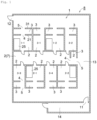
- the facility 8 comprises a clean room 1; multiple work booths 2 provided in the clean room 1 (nine work booths in this embodiment); and barrier sections corresponding, one-to-one, to the work booths 2 and provided in the clean room 1.
- the barrier sections are provided along entrances and exits of the work booths 2 and function to prevent airflow from the outside to the inside of the work booths 2 through the entrances and exits.
- each barrier section is composed of a support booth 3.
- the clean room 1 comprises, in addition to the work booths 2 and the support booths 3, a passage 13 that is adjacent to the support booths 3.
- Clean room 1 is a room in which the air in the room is maintained at a specific level of cleanliness.
- the clean room 1 is composed of one room in a building and its perimeter is surrounded by internal walls or partitions.
- the clean room 1 also comprises one or more entrances 11 and exits 12, specifically one entrance 11 and one exit 12.
- a changing room 14 is provided at a location that leads to the entrance 11.
- the changing room 14 is a room for workers to change their clothes when they move between the clean room 1 and the outside of the clean room 1.
- the level of cleanliness inside the clean room 1 is set to "grade B" as described below, whereas the level of cleanliness outside the clean room 1 is set to "grade C.” Therefore, when workers move between spaces with different cleanliness levels, the workers need to change their clothes in the changing room 14.
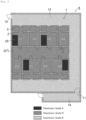
- Fig. 2 shows cleanliness areas in the facility 8.
- the grades of cleanliness shown in Fig. 2 are defined by using the maximum permitted number of airborne particles and the number of environmental microorganisms, as shown in Tables 1 and 2 below.
- the areas the inside of the work booths 2 and the areas that are outside the work booths 2 but are inside the clean room 1 are set to have the same level of cleanliness, grade B, as the zone that is outside the work booths 2 but is inside the clean room 1 (a passage 13 and support booths 3 in this embodiment).
- grade B grade B
- grade B + may be distinguished from each other in according to the monitoring frequency.
- the passage 13 is set to grade B, whereas the work booths 2 and the support booths 3 are set to grade B + . Further, biosafety cabinets 25 (BSC; biosafety cabinets) in the work booths 2 where the article is handled are set to grade A.
- BSC biosafety cabinets
- the "cleanliness-controlled area” as referred to herein indicates one or more locations in the areas where work is preformed, which are a location where an article is manufactured and a location where containers etc. before sterilization come into contact with the air in the facility 8.
- the "aseptic processing area” as referred to herein indicates one or more locations in the areas where work is preformed, which are a location where an article that needs to be handled by aseptic processing is prepared, a location where sterilized containers, etc. come into contact with the air in the facility 8, and a location where aseptic processing, such as a sterility test, is performed.
- Table 1 The maximum permitted number of airborne particles (particles/m 3 ) Supplementary note At rest In operation ⁇ 0.5 ⁇ m ⁇ 5 ⁇ m ⁇ 0.5 ⁇ m ⁇ 5 ⁇ m Grade A Aseptic processing area 3520 20 3520 20 Grade B + Cleanliness-controlled area 3520 29 352000 2900 High monitoring frequency Grade B 3520 29 352000 2900 Grade C 352000 2900 3520000 29000 Table 2 Airborne microorganisms Microorganisms on the surface Floating microorganisms Falling microorganism Instruments, walls, etc. Gloves (CFU/m 3 ) (CFU/4 hours) (CFU/24-30 cm 2 ) (CFU/5 fingers) Grade A ⁇ 1 ⁇ 1 ⁇ 1 ⁇ 1 Grade B 10 5 5 5 Grade C 100 50 25 -
- Work booths 2 are provided in the clean room 1 and are mainly used to manufacture an article. Each work booth 2 means one space formed by partitioning in the room. Although the work booths 2 are mainly used to manufacture an article, when work booths 2 are not used to manufacture an article, the process simulation test and/or maintenance of instruments and/or education and training of workers may be conducted in the work booths 2.
- the facility 8 comprises nine work booths 2 as multiple booths 2.
- the nine work booths 2 four work booths 2 (which are referred to as a "first group of work booths") are aligned in the first direction, and work booths 2 that are next to each other are adjacent to each other. Further, in the direction perpendicular to the first group of work booths (the second direction), four work booths 2 (which are referred to as a "second group of work booths”) are disposed through one work booth 2 (which may be referred to as a "delivery area 7").
- the four work booths 2, which are the second group of work booths, are arranged in the first direction, and the work booths 2 that are next to each other are adjacent to each other. Accordingly, the delivery area 7 is accessible to all work booths 2 other than itself.
- access means that a material for use in manufacturing of an article can be received therefrom or given thereto.
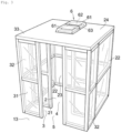
- Fig. 3 is a schematic perspective view of a work booth 2 and a support booth 3.
- Fig. 3 for the sake of explanation convenience, only one work booth 2 and one support booth 3 are shown. However, in fact, multiple work booths 2 are arranged as shown in Fig. 1 .
- each work booth 2 is kept at a positive pressure to thereby form airflow toward the corresponding support booth 3 through an entrance and exit (a first opening 4) formed in the front wall 21 and form airflow toward the passage 13 through an entrance and exit (a second opening 5) of the support booth 3 that faces the passage 13.
- a first opening 4 formed in the front wall 21
- a second opening 5 airflow toward the passage 13 through an entrance and exit (a second opening 5) of the support booth 3 that faces the passage 13.
- the support booth 3 constitutes a barrier section.
- a barrier section is provided along the entrance and exit (first opening 4) of each work booth 2 and functions to prevent airflow from the outside of the work booth 2 to the inside of the work booth 2 through the entrance and exit (first opening 4).
- the barrier section according to this embodiment is a support booth 3 as described above.
- the support booth 3 is provided between each work booth 2 and the passage 13. In the support booth 3, the air flows from inside of the work booth 2 through the entrance and exit (first opening 4) of the work booth 2 towards the passage 13. This prevents airflow from outside the work booth 2 toward the inside through the entrance and exit (first opening 4). As a result, this prevents microorganisms etc. from entering the work booth 2 on the airflow.
- the function of preventing microorganisms etc. from entering the work booth 2 is referred to as a "barrier function.
- the barrier function of the barrier section is achieved, for example, by maintaining each work booth 2 at a positive pressure relative to the passage 13. Alternatively, this function can also be achieved by creating airflow from each support booth 3 toward the passage 13.
- the barrier section may be configured to be formed by a door with which the entrance and exit of the work booth 2 is closed, or may be configured to be formed by an air curtain flowing along the entrance and exit of the work booth 2.
- the support booth 3 has the same level of cleanliness as that of the space within the clean room 1 (the passage 13 in this embodiment) and is a cleanliness-controlled area as shown in Fig. 2 . However, in this embodiment, the support booth 3 is monitored more frequently than the passage 13 and its level of cleanliness is set to grade B + .
- the support booth 3 is formed by being partitioned by a front wall 21 disposed between the work booth 2 and the support booth 3, an opposing wall 31 disposed spaced apart in the forward direction relative to the front wall 21, a pair of side walls 32, and a top wall 33.
- the top wall 33 and the top wall 24 are one piece, but may be separately formed.
- the adjacent side walls 22, 32 are separately formed but may be one piece.
- the facility 8 comprises a first opening 4 through which a support booth 3 and a work booth 2 corresponding to the support booth 3 communicate with each other (i.e., an entrance and exit of the work booth 2), and a second opening 5 through which the support booth 3 and the passage 13 communicate with each other (i.e., an entrance and exit facing the passage 13).
- the first opening 4 is formed by penetrating the front wall 21.
- the first opening 4 is formed large enough to allow a person to pass through.
- the first opening 4 does not have a door and is always open.
- the first opening 4 may be configured to be opened and closed with a door and can be closed with the door.
- the first opening 4 may be formed at the center of the front wall 21 in the width direction, or at an end portion of the front wall 21 in the width direction, or somewhere between the end portion and the center of the front wall 21 in the width direction.
- the second opening 5 is formed by penetrating the opposing wall 31.
- the second opening 5 is formed large enough to allow a person to pass through.
- the second opening 5 does not have a door and is always open.
- the second opening 5, as well as the first opening 4 may be configured to be opened and closed with a door and can be closed with the door.
- the second opening 5 is formed at a position that overlaps with the first opening 4 when viewed from a direction perpendicular to the opening surface.
- overlap referred to herein means that at least part overlaps.
- the first opening 4 may overlap with the second opening 5 entirely or partially.
- the position of the second opening 5 does not have to overlap with the first opening 4.
- the second opening 5 may be formed at the center of the opposing wall 31 in the width direction; at an end portion of the opposing wall 31 in the width direction; somewhere between the end portion and center of the opposing wall 31 in the width direction; or in the side walls 22, 32.
- the second opening 5 communicates with the first opening 4.
- the opening area of the second opening 5 is smaller than that of the first opening 4. Therefore, since each work booth 2 is kept in a positive pressure state by the positive pressure generator 6, the air that has flown into the corresponding support booth 3 through the first opening 4 creates airflow into a space inside the clean room 1 through the second opening 5.
- the support booth 3 functions as a barrier section and can more effectively prevent microorganisms etc. from entering the work booth 2 through the passage 13. Furthermore, changes in atmospheric pressure (disturbances) that occur when a worker passes through the passage 13 can be suppressed from affecting the cleanliness inside the work booth 2.
- the positive pressure generator 6 maintains each work booth 2 at a positive pressure. This creates airflow that flows out of the work booth 2 through the first opening 4 and can generate airflow that flows from the inside of the support booth 3 toward the passage 13 through the second opening 5.
- the air in the clean room 1 is introduced into the work booth 2 by means of multiple (two in this embodiment) air inflow devices 61 to make the inside of the work booth 2 at a positive pressure.
- the air inflow devices 61 are mounted on the top wall 24 facing the work booth 2.
- the air in the work booth 2 flows into the support booth 3 through the first opening 4, thus making the inside of the support booth 3 at a positive pressure.
- the positive pressure generators 6 create airflow from inside the support booth 3 toward the outside through the second opening 5 to the passage 13.
- Each air inflow device 61 is mounted in an installation hole (not shown) that penetrates through the top wall 24.
- the air inflow device 61 comprises a fan 62 for intake of air from the clean room 1 into the work booth 2 through an air inlet, and a filter 63.
- the filter 63 is provided in a flow channel through which the airflow formed by the fan 62 flows.
- the filter 63 prevents microorganisms etc. floating in the space and foreign matter, such as lint and dust, from passing therethrough.
- Examples of the filter 63 include medium performance filters, electrically charged filters, HEPA filters (high-efficiency particulate air filter), ULPA filters (ultra-low-penetration air filter), and the like. From the standpoint of performance and costs, HEPA filters are preferred.
- the positive pressure generator 6 comprises two air inflow devices 61.
- the number of the air inflow device 61 may be one or three or more.
- Air inlets are provided at several locations that face the passage 13, as shown in Fig. 1 .
- Each air inlet and the air inflow device 61 communicate with each other via an air flow passage (e.g., a duct).
- Multiple air inlets are provided spaced apart from each other along the passage 13. Air in the passage 13 is sucked into the air inlets to thereby create an airflow in the passage 13, whereby a flow along the passage 13 is generated in the passage 13.
- the air taken in from the multiple air inlets is supplied to the work booth 2 through the duct and the filter 63 and goes out from the second opening 5 to the passage 13.
- the air flowing in the passage 13 repeatedly circulates while passing through the filter 63.
- the clean room 1 is provided with a plurality of differential pressure dampers to adjust the pressure in the passage 13. Therefore, in conventional clean rooms 1, there is a possibility that microorganisms etc. that could cause contamination may leak out of the clean room 1 through the differential pressure dampers.
- the air that flows through the passage 13 is taken in through the air inlets facing the passage 13 and repeatedly circulates while passing through the filter 63. Therefore, even if contamination occurs in the passage 13 or in one of the work booths 2, microorganisms etc. that cause contamination are significantly prevented from escaping from the differential pressure dampers. As a result, cross-contamination to other adjacent clean rooms and/or spread of contamination to the environment can be inhibited.
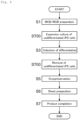
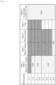
- Fig. 5 shows work booths 2 that are assigned to each step in manufacturing an article are indicated in black.
- the "work booth" numbering in Fig. 5 corresponds to the numbering of the work booths 2 in Fig. 1 .
- several work booths 2 are not in use during the manufacture of an article.
- the work booth 2 which is not being used in the manufacture of an article, is used to perform the process simulation test (described as "PST" in Fig. 5 ).
- the first step S1 and the second step S2 are performed in a work booth 2 numbered 1-1 for a period of approximately 4 to 7 weeks, during which process simulation tests are concurrently performed in work booths 2 numbered 1-2, 2-1, 2-2, 3-1, 3-2, 3-3, and 3-4.
- step S3 and the fourth step S4 are performed in work booths 2 numbered 1-1, 1-2, 2-1, 2-2, 3-1, 3-2, and 3-3 for a period of approximately 4 weeks, during which the process simulation test is concurrently performed in a work booth 2 numbered 3-4.
- an article is manufactured in at least one of the multiple work booths 2, whereas the process simulation test is performed in at least one other work booth 2 that is different from the work booth 2 used to manufacture the article.
- the manufacturing implementation method according to this embodiment does not require a large facility 8 when the manufacture of an article and the process simulation test are both performed.
- the sixth step S6 an important intermediate is thawed and patches are produced in response to an order from a hospital or other institutions (approximately 3 days). When there are no orders, this period is a break period during which the manufacture of an article is not performed in the work booth 2. Since the sixth step S6 is an order-basis step, the period during which the sixth step S6 is to be performed can be treated as a period during which no work booths 2 for manufacturing an article are present, and the process simulation test can be conducted in any of the work booths 2.
- the "important intermediate” as referred to herein means cardiomyocytes produced from iPS cells over a period of about two and a half months and cryopreserved.
- the portion other than the work booths 2 in the clean room 1 is referred to as "passage 13."
- the clean room 1 including the space corresponding to passage 13 in the clean room 1 is a clean room 1 as a "work room” and the portion other than the work booths 2 in the clean room 1 can also be used as a space for culturing.
- the clean room 1 is a "biological clean room.”
- this room can be an industrial clean room.
- first opening 4 and the second opening 5 are always open.
- first opening 4 and the second opening 5 may be configured to be opened and closed with the door and can be closed with a door.
- the space in which the article is manufactured can be kept sterile.
Landscapes
- Engineering & Computer Science (AREA)
- Architecture (AREA)
- Chemical & Material Sciences (AREA)
- Health & Medical Sciences (AREA)
- General Engineering & Computer Science (AREA)
- Mechanical Engineering (AREA)
- Combustion & Propulsion (AREA)
- General Chemical & Material Sciences (AREA)
- Veterinary Medicine (AREA)
- Pharmacology & Pharmacy (AREA)
- Life Sciences & Earth Sciences (AREA)
- Animal Behavior & Ethology (AREA)
- General Health & Medical Sciences (AREA)
- Public Health (AREA)
- Organic Chemistry (AREA)
- Nuclear Medicine, Radiotherapy & Molecular Imaging (AREA)
- Civil Engineering (AREA)
- Structural Engineering (AREA)
- Medicinal Chemistry (AREA)
- Chemical Kinetics & Catalysis (AREA)
- Bioinformatics & Cheminformatics (AREA)
- Ventilation (AREA)
- General Factory Administration (AREA)
Claims (10)
- Anlage (8), die Folgendes umfasst:einen Reinraum (1);mehrere Arbeitskabinen (2), die in dem Reinraum (1) bereitgestellt sind, wobei jede Arbeitskabine (2) eine erste Öffnung (4) umfasst und ferner einen Überdruckerzeuger (6) umfasst, um das Innere der Arbeitskabine (2) bei einem Überdruck zu halten;mehrere Unterstützungskabinen (3), die eins zu eins den mehreren Arbeitskabinen (2) entsprechen und angrenzend an die Arbeitskabinen (2) bereitgestellt sind, wobei jede Unterstützungskabine (3) eine zweite Öffnung (5) umfasst, die mit der ersten Öffnung (4) kommuniziert und die dazu ausgelegt ist, zu ermöglichen, dass Luft, die von der entsprechenden Arbeitskabine (2) durch die erste Öffnung (4) in die Unterstützungskabine (3) strömt, durch die zweite Öffnung (5) ausströmt und dadurch einen Luftstrom von der Außenseite der Arbeitskabine (2) zu deren Inneren hin verhindert, so eine Barrierefunktion aufweisend; und einen Durchgang (13), der im Reinraum (1) bereitgestellt ist und der zweiten Öffnung (5) jeder der mehreren Unterstützungskabinen (3) zugewandt ist;wobei Bereiche innerhalb der mehreren Arbeitskabinen (2) das gleiche Reinheitsniveau wie die Unterstützungskabinen (3) und der Durchgang (13) aufweisen.
- Anlage (8) nach Anspruch 1, wobei die Bereiche innerhalb der mehreren Arbeitskabinen (2) und der Unterstützungskabinen (3) und des Durchgangs (13) Bereiche mit gesteuerter Reinheit sind.
- Anlage (8) nach Anspruch 1 oder 2, wobei mindestens eine der mehreren Arbeitskabinen (2) einen aseptischen Verarbeitungsbereich im Inneren aufweist.
- Anlage (8) nach einem der Ansprüche 1 bis 3, wobei die mehreren Arbeitskabinen (2) jeweils Folgendes umfassen:ein Paar Seitenwände (22);eine Rückwand (23), die an den hinteren Enden des Paares von Seitenwänden (22) bereitgestellt ist;eine Vorderwand (21), die an den vorderen Enden des Paares von Seitenwänden (22) bereitgestellt ist und die erste Öffnung (4) umfasst; undeine obere Wand (24), die an den oberen Enden des Paares von Seitenwänden (22), der Rückwand (23) und der Vorderwand (21) bereitgestellt ist.
- Anlage (8) nach Anspruch 4, wobei der Überdruckerzeuger (6) mindestens eine Lufteinströmvorrichtung (61) umfasst, die an der oberen Wand (24) montiert und dazu ausgelegt ist, Luft in den Reinraum (1) in die entsprechende Arbeitskabine (2) einzuleiten.
- Anlage (8) nach Anspruch 5, wobei die Lufteinströmvorrichtung (61) einen Filter (63) umfasst, durch den Luft, die in die entsprechende Arbeitskabine (2) einzuleiten ist, hindurchströmt.
- Anlage (8) nach Anspruch 6, wobei die Lufteinströmvorrichtung (61) dazu ausgelegt ist, Luft, die von einem Lufteinlass angesaugt wird, der dem Durchgang (13) zugewandt ist, durch den Filter (63) in die entsprechende Arbeitskabine (2) einzuleiten.
- Umsetzungsverfahren zum Herstellen eines Artikels unter Verwendung der Anlage (8) nach einem der Ansprüche 1 bis 7, wobei die Herstellung eines Artikels in mindestens einer der mehreren Arbeitskabinen (2) durchgeführt wird und andere Arbeiten, die sich von der Herstellung eines Artikels unterscheiden, in einer Arbeitskabine (2) durchgeführt werden, die nicht die mindestens eine Arbeitskabine (2) ist, in der die Herstellung eines Artikels durchgeführt wird.
- Umsetzungsverfahren nach Anspruch 8 zur Herstellung eines Artikels, wobei die andere Arbeit Folgendes ist: ein Prozesssimulationstest, um zu bestätigen, ob Sterilität bei der Herstellung eines Artikels angemessen ist, Wartung von Instrumenten, die in der anderen Arbeitskabine (2) installiert sind, oder Ausbildung und Weiterbildung eines Arbeiters, der an der Herstellung eines Artikels beteiligt ist.
- Umsetzungsverfahren nach Anspruch 8 oder Anspruch 9 zur Herstellung eines Artikels, wobei der Artikel ein zelluläres und gewebebasiertes Produkt beinhaltet.
Applications Claiming Priority (2)
| Application Number | Priority Date | Filing Date | Title |
|---|---|---|---|
| JP2019226426 | 2019-12-16 | ||
| PCT/JP2020/046041 WO2021125042A1 (ja) | 2019-12-16 | 2020-12-10 | 設備及びこれを用いた物品の製造の実施方法 |
Publications (4)
| Publication Number | Publication Date |
|---|---|
| EP4079376A1 EP4079376A1 (de) | 2022-10-26 |
| EP4079376A4 EP4079376A4 (de) | 2024-02-14 |
| EP4079376C0 EP4079376C0 (de) | 2025-03-05 |
| EP4079376B1 true EP4079376B1 (de) | 2025-03-05 |
Family
ID=76477504
Family Applications (1)
| Application Number | Title | Priority Date | Filing Date |
|---|---|---|---|
| EP20903566.6A Active EP4079376B1 (de) | 2019-12-16 | 2020-12-10 | Anlage und implementierungsverfahren zur herstellung eines artikels mit dieser anlage |
Country Status (9)
| Country | Link |
|---|---|
| US (1) | US12455083B2 (de) |
| EP (1) | EP4079376B1 (de) |
| JP (1) | JP7609440B2 (de) |
| KR (1) | KR20220113452A (de) |
| CN (1) | CN114829719A (de) |
| AU (1) | AU2020408633A1 (de) |
| CA (1) | CA3161651A1 (de) |
| SA (1) | SA522432979B1 (de) |
| WO (1) | WO2021125042A1 (de) |
Families Citing this family (2)
| Publication number | Priority date | Publication date | Assignee | Title |
|---|---|---|---|---|
| JP7746535B2 (ja) * | 2022-03-09 | 2025-09-30 | 日立グローバルライフソリューションズ株式会社 | クリーンルーム施設 |
| CN116607623B (zh) * | 2023-05-19 | 2025-11-11 | 中船第九设计研究院工程有限公司 | 一种三级生物安全实验室二级防护屏障的实验室布局结构 |
Family Cites Families (17)
| Publication number | Priority date | Publication date | Assignee | Title |
|---|---|---|---|---|
| JPH05149605A (ja) * | 1991-11-30 | 1993-06-15 | Toshiba Corp | 空気調和機 |
| JP2002147811A (ja) | 2000-11-08 | 2002-05-22 | Sharp Corp | クリーンルーム |
| JP2002195620A (ja) * | 2000-12-27 | 2002-07-10 | Sankyo Seiki Mfg Co Ltd | クリーン作業モジュール及びクリーントンネル |
| JP4632737B2 (ja) | 2004-09-29 | 2011-02-16 | 三洋電機株式会社 | 細胞培養施設 |
| KR100707985B1 (ko) * | 2006-03-10 | 2007-04-16 | 세원셀론텍(주) | 세포치료제를 생산 및 보관하기 위한 모듈 장치 |
| JP4971006B2 (ja) * | 2007-03-30 | 2012-07-11 | 安藤建設株式会社 | クリーンルームの改築方法及び改築用仮設設備 |
| DK2382514T3 (en) * | 2008-12-23 | 2019-02-04 | Xoma Us Llc | Flexible production system |
| CN102575858B (zh) * | 2009-08-16 | 2015-02-04 | G-Con制造有限公司 | 组件式自足可移动的净化房 |
| JP6427269B2 (ja) * | 2014-07-11 | 2018-11-21 | ジー−コン マニュファクチャリング インク. | クリーンルーム、隔離若しくは閉じ込めキュービクル、ポッド、又はモジュールにユーティリティを供給するモジュール式部分 |
| US20180005156A1 (en) | 2015-01-20 | 2018-01-04 | Ge Healthcare Bio-Sciences Corp. | Process Simulation in a Cell Processing Facility |
| CN104847139B (zh) * | 2015-04-13 | 2017-09-29 | 上海安集协康生物技术股份有限公司 | 细胞生产洁净厂房 |
| CN207260645U (zh) * | 2017-07-28 | 2018-04-20 | 广东依浦赛生物科技有限公司 | 医用细胞制备间的建筑系统 |
| JP6978291B2 (ja) | 2017-11-27 | 2021-12-08 | ダイダン株式会社 | クリーンブース |
| JP7039123B2 (ja) * | 2017-11-30 | 2022-03-22 | ダイダン株式会社 | クリーンブース |
| CN107965167B (zh) * | 2017-12-20 | 2019-05-10 | 北京臻惠康生物科技有限公司 | 一种细胞制备实验室设计方案 |
| CN109469362A (zh) * | 2018-10-23 | 2019-03-15 | 广州达意隆包装机械股份有限公司 | 一种实验室 |
| EP4071415B1 (de) * | 2019-12-04 | 2025-10-01 | Hitachi Global Life Solutions, Inc. | Klimatisierungssystem |
-
2020
- 2020-12-10 WO PCT/JP2020/046041 patent/WO2021125042A1/ja not_active Ceased
- 2020-12-10 CN CN202080087161.2A patent/CN114829719A/zh active Pending
- 2020-12-10 JP JP2021565531A patent/JP7609440B2/ja active Active
- 2020-12-10 US US17/785,245 patent/US12455083B2/en active Active
- 2020-12-10 EP EP20903566.6A patent/EP4079376B1/de active Active
- 2020-12-10 AU AU2020408633A patent/AU2020408633A1/en not_active Abandoned
- 2020-12-10 CA CA3161651A patent/CA3161651A1/en active Pending
- 2020-12-10 KR KR1020227023054A patent/KR20220113452A/ko active Pending
-
2022
- 2022-06-13 SA SA522432979A patent/SA522432979B1/ar unknown
Also Published As
| Publication number | Publication date |
|---|---|
| US12455083B2 (en) | 2025-10-28 |
| EP4079376A4 (de) | 2024-02-14 |
| KR20220113452A (ko) | 2022-08-12 |
| EP4079376A1 (de) | 2022-10-26 |
| US20230032285A1 (en) | 2023-02-02 |
| SA522432979B1 (ar) | 2024-10-08 |
| EP4079376C0 (de) | 2025-03-05 |
| CA3161651A1 (en) | 2021-06-24 |
| CN114829719A (zh) | 2022-07-29 |
| WO2021125042A1 (ja) | 2021-06-24 |
| AU2020408633A1 (en) | 2022-07-21 |
| JP7609440B2 (ja) | 2025-01-07 |
| JPWO2021125042A1 (de) | 2021-06-24 |
Similar Documents
| Publication | Publication Date | Title |
|---|---|---|
| EP3165283B1 (de) | Sicherheitsschrank | |
| EP4079376B1 (de) | Anlage und implementierungsverfahren zur herstellung eines artikels mit dieser anlage | |
| WO2007105844A1 (en) | Facility module for production and storage of cell therapy product | |
| JP4632806B2 (ja) | 細胞培養施設 | |
| McGarrity et al. | Procedures to reduce contamination of cell cultures | |
| EP4026530B1 (de) | Verfahren zum betrieb eine gebäudeeinrichtung | |
| US11112143B2 (en) | Fan filter unit, sterilization apparatus and clean room | |
| JP2003047457A (ja) | ベクター作製施設およびベクター作製方法 | |
| JP5421203B2 (ja) | 細胞培養施設 | |
| JP5615417B2 (ja) | ユニット型細胞培養施設 | |
| JP4632737B2 (ja) | 細胞培養施設 | |
| KR100745362B1 (ko) | 세포치료제 설비의 사용방법 및 이를 이용한 네트워크기반의 프랜차이즈 마켓 비즈니스 방법 | |
| RU2615432C1 (ru) | Асептический изолированный блок | |
| CN114945658B (zh) | 无化学杀菌剂的无菌细胞处理及生产 | |
| Fedor et al. | Effectiveness of anti-epidemic measures on ensuring indoor air quality of cleanrooms in a tertiary care hospital. | |
| McDade et al. | Chapter V Principles and Applications of Laminar-flow Devices | |
| Styczyński et al. | Protective environment in hematopoietic cell transplantation centers: results of a survey of the Polish Federation of Bone Marrow Transplant Centers | |
| KR102590766B1 (ko) | 군집시설의 공기질 개선 모듈 | |
| Aldi et al. | Isolator for the CAR-T-Cell Therapy | |
| CN208877401U (zh) | 原位消毒效果验证单元及其应用的生物污染空气过滤装置 | |
| Morrell | Efficacy of mini-containment units in isolating mice from micro-organisms | |
| White | Protective Air Enclosures for Nursing | |
| Whyte et al. | Assessment of degree of risk from sources of microbial contamination in cleanrooms; 3: Overall application | |
| El Assaad-Idrissi et al. | COMPARATIVE STUDY OF THE AIR HANDLING SYSTEM BY FILTRATION AND HYDRO-PHOTO-IONIZATION IN HOSPITAL STERILIZATION SERVICES | |
| Bates et al. | Thermo Scientific Cell Locker System Prevents Entry of Microorganisms for Protection of Sensitive Cell Cultures |
Legal Events
| Date | Code | Title | Description |
|---|---|---|---|
| STAA | Information on the status of an ep patent application or granted ep patent |
Free format text: STATUS: THE INTERNATIONAL PUBLICATION HAS BEEN MADE |
|
| PUAI | Public reference made under article 153(3) epc to a published international application that has entered the european phase |
Free format text: ORIGINAL CODE: 0009012 |
|
| STAA | Information on the status of an ep patent application or granted ep patent |
Free format text: STATUS: REQUEST FOR EXAMINATION WAS MADE |
|
| 17P | Request for examination filed |
Effective date: 20220715 |
|
| AK | Designated contracting states |
Kind code of ref document: A1 Designated state(s): AL AT BE BG CH CY CZ DE DK EE ES FI FR GB GR HR HU IE IS IT LI LT LU LV MC MK MT NL NO PL PT RO RS SE SI SK SM TR |
|
| DAV | Request for validation of the european patent (deleted) | ||
| DAX | Request for extension of the european patent (deleted) | ||
| A4 | Supplementary search report drawn up and despatched |
Effective date: 20240116 |
|
| RIC1 | Information provided on ipc code assigned before grant |
Ipc: A61K 35/545 20150101ALI20240110BHEP Ipc: E04H 5/02 20060101ALI20240110BHEP Ipc: A61P 43/00 20060101AFI20240110BHEP |
|
| GRAP | Despatch of communication of intention to grant a patent |
Free format text: ORIGINAL CODE: EPIDOSNIGR1 |
|
| STAA | Information on the status of an ep patent application or granted ep patent |
Free format text: STATUS: GRANT OF PATENT IS INTENDED |
|
| RIC1 | Information provided on ipc code assigned before grant |
Ipc: F24F 9/00 20060101ALI20240918BHEP Ipc: F24F 3/167 20210101ALI20240918BHEP Ipc: A61K 35/545 20150101ALI20240918BHEP Ipc: E04H 5/02 20060101ALI20240918BHEP Ipc: A61P 43/00 20060101AFI20240918BHEP |
|
| INTG | Intention to grant announced |
Effective date: 20241002 |
|
| GRAS | Grant fee paid |
Free format text: ORIGINAL CODE: EPIDOSNIGR3 |
|
| GRAA | (expected) grant |
Free format text: ORIGINAL CODE: 0009210 |
|
| STAA | Information on the status of an ep patent application or granted ep patent |
Free format text: STATUS: THE PATENT HAS BEEN GRANTED |
|
| AK | Designated contracting states |
Kind code of ref document: B1 Designated state(s): AL AT BE BG CH CY CZ DE DK EE ES FI FR GB GR HR HU IE IS IT LI LT LU LV MC MK MT NL NO PL PT RO RS SE SI SK SM TR |
|
| REG | Reference to a national code |
Ref country code: GB Ref legal event code: FG4D |
|
| REG | Reference to a national code |
Ref country code: CH Ref legal event code: EP |
|
| REG | Reference to a national code |
Ref country code: IE Ref legal event code: FG4D |
|
| REG | Reference to a national code |
Ref country code: DE Ref legal event code: R096 Ref document number: 602020047435 Country of ref document: DE |
|
| U01 | Request for unitary effect filed |
Effective date: 20250403 |
|
| U07 | Unitary effect registered |
Designated state(s): AT BE BG DE DK EE FI FR IT LT LU LV MT NL PT RO SE SI Effective date: 20250514 |
|
| PG25 | Lapsed in a contracting state [announced via postgrant information from national office to epo] |
Ref country code: RS Free format text: LAPSE BECAUSE OF FAILURE TO SUBMIT A TRANSLATION OF THE DESCRIPTION OR TO PAY THE FEE WITHIN THE PRESCRIBED TIME-LIMIT Effective date: 20250605 |
|
| PG25 | Lapsed in a contracting state [announced via postgrant information from national office to epo] |
Ref country code: ES Free format text: LAPSE BECAUSE OF FAILURE TO SUBMIT A TRANSLATION OF THE DESCRIPTION OR TO PAY THE FEE WITHIN THE PRESCRIBED TIME-LIMIT Effective date: 20250305 |
|
| PG25 | Lapsed in a contracting state [announced via postgrant information from national office to epo] |
Ref country code: NO Free format text: LAPSE BECAUSE OF FAILURE TO SUBMIT A TRANSLATION OF THE DESCRIPTION OR TO PAY THE FEE WITHIN THE PRESCRIBED TIME-LIMIT Effective date: 20250605 |
|
| PG25 | Lapsed in a contracting state [announced via postgrant information from national office to epo] |
Ref country code: HR Free format text: LAPSE BECAUSE OF FAILURE TO SUBMIT A TRANSLATION OF THE DESCRIPTION OR TO PAY THE FEE WITHIN THE PRESCRIBED TIME-LIMIT Effective date: 20250305 |
|
| PG25 | Lapsed in a contracting state [announced via postgrant information from national office to epo] |
Ref country code: GR Free format text: LAPSE BECAUSE OF FAILURE TO SUBMIT A TRANSLATION OF THE DESCRIPTION OR TO PAY THE FEE WITHIN THE PRESCRIBED TIME-LIMIT Effective date: 20250606 |
|
| PG25 | Lapsed in a contracting state [announced via postgrant information from national office to epo] |
Ref country code: SM Free format text: LAPSE BECAUSE OF FAILURE TO SUBMIT A TRANSLATION OF THE DESCRIPTION OR TO PAY THE FEE WITHIN THE PRESCRIBED TIME-LIMIT Effective date: 20250305 |
|
| PG25 | Lapsed in a contracting state [announced via postgrant information from national office to epo] |
Ref country code: PL Free format text: LAPSE BECAUSE OF FAILURE TO SUBMIT A TRANSLATION OF THE DESCRIPTION OR TO PAY THE FEE WITHIN THE PRESCRIBED TIME-LIMIT Effective date: 20250305 |
|
| PG25 | Lapsed in a contracting state [announced via postgrant information from national office to epo] |
Ref country code: CZ Free format text: LAPSE BECAUSE OF FAILURE TO SUBMIT A TRANSLATION OF THE DESCRIPTION OR TO PAY THE FEE WITHIN THE PRESCRIBED TIME-LIMIT Effective date: 20250305 |
|
| PG25 | Lapsed in a contracting state [announced via postgrant information from national office to epo] |
Ref country code: SK Free format text: LAPSE BECAUSE OF FAILURE TO SUBMIT A TRANSLATION OF THE DESCRIPTION OR TO PAY THE FEE WITHIN THE PRESCRIBED TIME-LIMIT Effective date: 20250305 |
|
| PG25 | Lapsed in a contracting state [announced via postgrant information from national office to epo] |
Ref country code: IS Free format text: LAPSE BECAUSE OF FAILURE TO SUBMIT A TRANSLATION OF THE DESCRIPTION OR TO PAY THE FEE WITHIN THE PRESCRIBED TIME-LIMIT Effective date: 20250705 |
|
| U20 | Renewal fee for the european patent with unitary effect paid |
Year of fee payment: 6 Effective date: 20251118 |
|
| PGFP | Annual fee paid to national office [announced via postgrant information from national office to epo] |
Ref country code: GB Payment date: 20251113 Year of fee payment: 6 |
|
| PLBE | No opposition filed within time limit |
Free format text: ORIGINAL CODE: 0009261 |
|
| STAA | Information on the status of an ep patent application or granted ep patent |
Free format text: STATUS: NO OPPOSITION FILED WITHIN TIME LIMIT |
|
| REG | Reference to a national code |
Ref country code: CH Ref legal event code: L10 Free format text: ST27 STATUS EVENT CODE: U-0-0-L10-L00 (AS PROVIDED BY THE NATIONAL OFFICE) Effective date: 20260114 |
|
| 26N | No opposition filed |
Effective date: 20251208 |