EP4074478B1 - Stanzwerkzeug - Google Patents
Stanzwerkzeug Download PDFInfo
- Publication number
- EP4074478B1 EP4074478B1 EP22160637.9A EP22160637A EP4074478B1 EP 4074478 B1 EP4074478 B1 EP 4074478B1 EP 22160637 A EP22160637 A EP 22160637A EP 4074478 B1 EP4074478 B1 EP 4074478B1
- Authority
- EP
- European Patent Office
- Prior art keywords
- cutting
- die
- blade
- punching
- punching tool
- Prior art date
- Legal status (The legal status is an assumption and is not a legal conclusion. Google has not performed a legal analysis and makes no representation as to the accuracy of the status listed.)
- Active
Links
Images

Classifications
-
- B—PERFORMING OPERATIONS; TRANSPORTING
- B26—HAND CUTTING TOOLS; CUTTING; SEVERING
- B26F—PERFORATING; PUNCHING; CUTTING-OUT; STAMPING-OUT; SEVERING BY MEANS OTHER THAN CUTTING
- B26F1/00—Perforating; Punching; Cutting-out; Stamping-out; Apparatus therefor
- B26F1/38—Cutting-out; Stamping-out
- B26F1/44—Cutters therefor; Dies therefor
-
- B—PERFORMING OPERATIONS; TRANSPORTING
- B26—HAND CUTTING TOOLS; CUTTING; SEVERING
- B26D—CUTTING; DETAILS COMMON TO MACHINES FOR PERFORATING, PUNCHING, CUTTING-OUT, STAMPING-OUT OR SEVERING
- B26D1/00—Cutting through work characterised by the nature or movement of the cutting member or particular materials not otherwise provided for; Apparatus or machines therefor; Cutting members therefor
- B26D1/01—Cutting through work characterised by the nature or movement of the cutting member or particular materials not otherwise provided for; Apparatus or machines therefor; Cutting members therefor involving a cutting member which does not travel with the work
- B26D1/04—Cutting through work characterised by the nature or movement of the cutting member or particular materials not otherwise provided for; Apparatus or machines therefor; Cutting members therefor involving a cutting member which does not travel with the work having a linearly-movable cutting member
- B26D1/06—Cutting through work characterised by the nature or movement of the cutting member or particular materials not otherwise provided for; Apparatus or machines therefor; Cutting members therefor involving a cutting member which does not travel with the work having a linearly-movable cutting member wherein the cutting member reciprocates
- B26D1/08—Cutting through work characterised by the nature or movement of the cutting member or particular materials not otherwise provided for; Apparatus or machines therefor; Cutting members therefor involving a cutting member which does not travel with the work having a linearly-movable cutting member wherein the cutting member reciprocates of the guillotine type
- B26D1/085—Cutting through work characterised by the nature or movement of the cutting member or particular materials not otherwise provided for; Apparatus or machines therefor; Cutting members therefor involving a cutting member which does not travel with the work having a linearly-movable cutting member wherein the cutting member reciprocates of the guillotine type for thin material, e.g. for sheets, strips or the like
-
- B—PERFORMING OPERATIONS; TRANSPORTING
- B26—HAND CUTTING TOOLS; CUTTING; SEVERING
- B26D—CUTTING; DETAILS COMMON TO MACHINES FOR PERFORATING, PUNCHING, CUTTING-OUT, STAMPING-OUT OR SEVERING
- B26D7/00—Details of apparatus for cutting, cutting-out, stamping-out, punching, perforating, or severing by means other than cutting
- B26D7/18—Means for removing cut-out material or waste
- B26D7/1818—Means for removing cut-out material or waste by pushing out
-
- B—PERFORMING OPERATIONS; TRANSPORTING
- B26—HAND CUTTING TOOLS; CUTTING; SEVERING
- B26F—PERFORATING; PUNCHING; CUTTING-OUT; STAMPING-OUT; SEVERING BY MEANS OTHER THAN CUTTING
- B26F1/00—Perforating; Punching; Cutting-out; Stamping-out; Apparatus therefor
- B26F1/38—Cutting-out; Stamping-out
- B26F1/40—Cutting-out; Stamping-out using a press, e.g. of the ram type
-
- B—PERFORMING OPERATIONS; TRANSPORTING
- B26—HAND CUTTING TOOLS; CUTTING; SEVERING
- B26D—CUTTING; DETAILS COMMON TO MACHINES FOR PERFORATING, PUNCHING, CUTTING-OUT, STAMPING-OUT OR SEVERING
- B26D1/00—Cutting through work characterised by the nature or movement of the cutting member or particular materials not otherwise provided for; Apparatus or machines therefor; Cutting members therefor
- B26D1/0006—Cutting members therefor
- B26D2001/0053—Cutting members therefor having a special cutting edge section or blade section
-
- B—PERFORMING OPERATIONS; TRANSPORTING
- B26—HAND CUTTING TOOLS; CUTTING; SEVERING
- B26F—PERFORATING; PUNCHING; CUTTING-OUT; STAMPING-OUT; SEVERING BY MEANS OTHER THAN CUTTING
- B26F1/00—Perforating; Punching; Cutting-out; Stamping-out; Apparatus therefor
- B26F1/38—Cutting-out; Stamping-out
- B26F1/44—Cutters therefor; Dies therefor
- B26F2001/4472—Cutting edge section features
-
- B—PERFORMING OPERATIONS; TRANSPORTING
- B26—HAND CUTTING TOOLS; CUTTING; SEVERING
- B26F—PERFORATING; PUNCHING; CUTTING-OUT; STAMPING-OUT; SEVERING BY MEANS OTHER THAN CUTTING
- B26F1/00—Perforating; Punching; Cutting-out; Stamping-out; Apparatus therefor
- B26F1/38—Cutting-out; Stamping-out
- B26F1/44—Cutters therefor; Dies therefor
- B26F2001/449—Cutters therefor; Dies therefor for shearing, e.g. with adjoining or abutting edges
Definitions
- the invention relates to a punching tool for cutting plastic-based film elements, with a punching stamp unit which has a plurality of knife holders, to which at least one punching knife having a cutting wedge that tapers into a cutting blade with a cutting edge is attached, and with a die assigned to the punching stamp unit and opposite it for receiving of the film element to be processed, wherein the punch unit is mounted relatively movably relative to the die during a punching stroke in a cutting direction between a starting position and a processing position, the cutting wedges of the punching knives in the processing position being immersed in the film element to be processed and along an edge length of the cutting edge Create cutting line in the film system.
- Such punching tools have been known for a long time, see for example FR-A-3022818 .
- Such a punching tool with a pressing surface downstream of the cutting edge and which can be brought into contact with an upper side of the part of the film element to be processed facing away from the die is made from the EP-3566832-A1 known, but the pressing surface is part of the knife carrier.
- the task of such punching tools is to cut large-area film elements made of plastic, which can be, for example, a two-dimensional large-area film or a three-dimensional film element.
- Such three-dimensional film elements can be, for example, yogurt cups, which are to be made up in a certain way after production, for example to be separated or in certain, for example four-packs, Cut out groups of six or eight.
- Important components of such punching tools are punching knives, which create a cutting line when they are immersed in the film element.
- PET-based film elements are tougher compared to polystyrene-based film elements, so that the punching knives are exposed to higher loads.
- the object of the invention is to create a punching tool of the type mentioned at the beginning, in which the processing of plastic-based film elements, in particular those made of made of thermoplastic material, is more process-reliable than conventional punching tools.
- the punching tool according to the invention is characterized in that the cutting blade has a first blade surface facing the die and a second blade surface facing away from the die, with a second blade surface extending transversely to the cutting direction downstream of the cutting edge during the cutting process and an upper side of the die
- the part of the film element to be processed that faces away is connected to a pressing surface that can be brought into contact.
- the pressing surface downstream of the cutting edge during the cutting process causes the part of the film element to be processed facing away from the die to be pushed away in the vertical direction from the part of the film element facing the die, which rests in particular in a fixed manner on the upper step of the die.
- the part of the film element to be processed facing away from the die is pushed downwards away from the part of the film element facing the die during the cutting process, in particular the shear cutting movement carried out by means of the punching knife, as a result of which material bridges that are not separated by the cutting process are stretched and caused to come off.
- the first blade surface is aligned parallel to the wide blade surface.
- the pressing surface is aligned at least essentially at right angles to the second blade surface.
- a cutting edge width of the cutting edge extending transversely to the cutting direction is smaller than a pressing surface width of the pressing surface extending transversely to the cutting direction.
- the pressing surface width of the pressing surface is expediently designed in such a way that a pressing process of the pressing surface following the cutting process of the cutting edge has a sufficient contact area available on the part of the film element to be processed that faces away from the top of the die.
- the ratio of cutting edge width to pressing surface width is in the range from 0.1 to 0.8, in particular 0.5 to 0.7.
- a blade surface height of the second blade surface extending from the cutting edge to the pressing surface is greater than or equal to the pressing surface width.
- the pressing surface width is greater than the blade surface height of the second blade surface, but it is preferred to dimension the blade surface height greater than or equal to the pressing surface width.
- the ratio of blade surface height to pressing surface width is in the range from 1.0 to 5.0, in particular 1.5 to 3.0.
- the cutting wedge has a first wedge surface facing the die and a second wedge surface aligned obliquely to the first wedge surface and facing away from the die, the course of the second wedge surface up to the cutting edge being interrupted by the pressing surface forming a shoulder.
- the first blade surface of the cutting blade forms a portion of the first wedge surface, which is aligned in the cutting direction with the first wedge surface.
- the punching knife is designed in one piece and the cutting blade and pressing surface are formed during the production of the punching knife.
- the punching knife can therefore be designed as a monolith on which all functional sections required for the cutting process (cutting edge, pressing surface) are formed.
- the punching knife is designed in several parts, with a plate-shaped cutting blade element and a wedge-shaped blade carrier, to which the cutting blade element is attached in such a way that a front lower end of the blade carrier covers the pressing surface and a projection of the cutting blade element beyond the lower end of the blade carrier forms the cutting blade.
- the punching knife prefferably designed as a star or contour punch, with which it is possible to punch out flat areas of a film element to be processed. It is expediently possible to assign a pressing surface to each of the cutting edges of the contour or star punch.
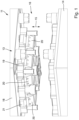
- the Figures 1 to 5 show a preferred exemplary embodiment of the punching tool 11 according to the invention for cutting plastic-based film elements 12.
- the punching tool 11 according to the invention is described below by way of example using a three-dimensional PET-based film element 12, which can be, for example, yogurt cups.
- a three-dimensional PET-based film element 12 can be, for example, yogurt cups.
- the punching tool 11 according to the invention it is possible to cut or assemble completely different plastic-based film elements 12, for example two-dimensional plastic films.
- the punching tool 11 according to the invention it is possible, for example, to assemble two- or three-dimensional PET, PP, PLA or PVC-based film elements.
- the aim of stamping the plastic, in particular PET-based, film elements 12 is to assemble the film elements 12 from a virtually endless pipe string into individual groups or individual elements.
- the punching tool 11 has a punch unit 13, which forms the movable part of the punching tool.
- a die 14 for receiving the film element 12 to be processed is arranged opposite the punch unit 13, the punch unit 13 relative to the die 14 during a punching stroke taking place in a lifting direction or cutting direction 15 between a starting position ( Figure 1 ) and a processing position 17 ( Figures 3 and 4 ) is mounted relatively movably.
- the punch unit 13 has a base plate 18, which is shown as an example in a rectangular shape. Several functional components of the punch unit 13 are attached to the base plate 18.
- the functional components include several punching knife modules 19, each of which has at least one punching knife 20, which is mounted, for example in a height-adjustable manner, on a knife carrier (not shown), the knife carrier being connected to the base plate 18 via a base body 21.
- the punching knives 20 are each releasably attached to an associated knife seat (not shown) of the knife carrier by means of fastening means.
- the functionality and structure or the geometry and contour of the punching knife 20 on a single punching knife 20 are explained below.
- the other punching knives of the punching stamp unit or at least a group of the punching knives of the punching stamp unit 13 are also designed in the same way.
- Fastening screws are used as fastening means, for example, the associated through holes 22a, 22b ( Figures 2 to 4 ) in the punching knife 20 and are sunk into assigned recesses (not shown) in a bearing section of the knife carrier.
- a tuning element in the form of a relatively thin tuning disk can be arranged between the seat surface of the knife seat and the punching knife 20.
- the punching knife 20 has a bearing or clamping section 23, which is penetrated transversely to the cutting direction 15 by the two through holes 22a, 22b. As already described above, the punching knife 20 is fastened to the associated knife seat of the knife carrier via the clamping section 23 and the through holes 22a, 22b using suitable fastening screws.
- a cutting wedge 24 adjoins the clamping section 23 along the cutting direction 15, at the lower end of which a cutting blade 25 is formed or arranged.
- the cutting wedge 24 has a first wedge surface 26 facing the die 14 and a second wedge surface 27 aligned obliquely to the first wedge surface 26 and facing away from the die 14.
- the blade surfaces of the cutting blade are preferably aligned parallel to one another.
- the cutting blade 25 has a first blade surface 28 facing the die 14 and a second blade surface 29 aligned parallel to the first blade surface 28 and facing away from the die 14.
- a cutting edge 30 which is designed to create a cutting line in the film element 12 to be processed.
- the cutting edge 30 is designed as a straight, uncontoured cutting edge over its edge length.
- other types of cutting edges for example those with a sawtooth-like cutting contour.
- the cutting edge itself to be wedge-shaped, for example by two mutually converging cutting edge sections which, for example, form a cutting edge wedge in the middle.
- An essential aspect of the invention is that the second blade surface 29 is adjoined by a pressing surface 33 which extends transversely to the cutting direction 15 and which is downstream of the cutting edge 30 during the cutting process and can be brought into contact with a top side 31 of the part 32 of the film element 12 being processed that is facing away from the die 14 .
- the pressing surface 33 is aligned at least substantially at right angles, in particular at right angles to the second blade surface 29. As further in Figure 5 shown is the course of the oblique second wedge surface 27 up to the cutting edge 30 interrupted by the pressing surface 33 forming a shoulder or step.
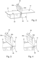
- the Figures 1 to 4 show a first embodiment of the punching knife 20.
- the punching knife 20 is a monolith, for example made of tool steel or hard metal.
- the punching knife 20 can be provided with a surface coating.
- the functional sections of the punching knife i.e. the wedge surfaces 26, 27, the cutting blade 25 with the blade surfaces 28, 29, the cutting edge 30 and the pressing surface 33 are also formed during the production of the punching knife.
- the Figure 5 shows a second embodiment of the punching knife.
- the punching knife 20 is designed in several parts, with a plate-shaped cutting blade element 34, which can consist, for example, of a relatively thin, in particular very stiff, blade suitable for a cutting process, and a wedge-shaped blade carrier 35, on which the cutting blade element 34 can be attached by means of suitable fastening means is attached that a front lower end of the blade carrier 35 forms the pressing surface 33 and a projection of the cutting blade element 34 beyond the lower end of the blade carrier 35 forms the cutting blade 25.
- a plate-shaped cutting blade element 34 which can consist, for example, of a relatively thin, in particular very stiff, blade suitable for a cutting process
- a wedge-shaped blade carrier 35 on which the cutting blade element 34 can be attached by means of suitable fastening means is attached that a front lower end of the blade carrier 35 forms the pressing surface 33 and a projection of the cutting blade element 34 beyond the lower end of the blade carrier 35 forms the cutting blade 25.
- a cutting edge width b1 of the cutting edge 30 extending transversely to the cutting direction 15 is smaller than a pressing surface width b2 of the pressing surface 33 extending transversely to the cutting direction 15.
- the ratio of cutting edge width to pressing surface width b1/b2 is in the range 0.1 to 0.8, in particular 0.5 to 0.7.
- a blade surface height h1 of the second blade surface 29 extending from the cutting edge 30 to the pressing surface 33 is greater than or equal to the pressing surface width b1.
- the ratio of blade surface height to pressing surface width h1/b2 is in the range from 1.0 to 5.0, in particular 1.5 to 3.0.
- this ratio can be changed subsequently, for example by changing the position of the cutting blade element 34 with respect to the blade carrier 35, so that the projection of the cutting blade element 34 beyond the lower end of the blade carrier 35 can be varied.
- the method according to the invention for cutting plastic-based film elements using the punching tool 11 according to the invention takes place according to the following steps: First, the punch unit 13 is in the raised starting position 16. Depending on the manufacturing task, groups of punching knives are then arranged so that, for example, a group of four, for example four yogurt cups, or other groupings can be cut out of the film element 12 to be processed.
- the film element 12 to be processed is inserted into the die 14.
- the die 14 has a die cavity 36 into which the punching knife 20 can move during the cutting process.
- the punch unit 13 and the die 14 are relative to one another moved, for example by moving the punch unit 13 downwards towards the die 24.
- the cutting wedge 24 and here in particular the cutting length with the cutting edge 30 arranged on the underside comes into contact with the top of the film element 12 to be processed and the cutting edges 30 of the punching knives 20 each produce cutting lines in the film element 12.
- the punch unit 13 is moved further downwards and moves further into the die cavity 36 of the die 34, whereby the pressing surface 33 of a respective punching knife 20 comes into contact with the top side 31 of the part 32 of the film element 12 to be processed facing away from the die and this Part 32 presses further into the matrix cavity 36.
- cutting blades 25 that have become blunter during the punching process can also be used, since the turning process ensures reliable separation of the film element to be processed. This increases the service life of the punching knives 20.
Landscapes
- Life Sciences & Earth Sciences (AREA)
- Forests & Forestry (AREA)
- Engineering & Computer Science (AREA)
- Mechanical Engineering (AREA)
- Perforating, Stamping-Out Or Severing By Means Other Than Cutting (AREA)
Description
- Die Erfindung betrifft Stanzwerkzeug zum Schneiden von kunststoffbasierten Folienelementen, mit einer Stanzstempeleinheit, die mehrere Messerträger aufweist, an denen jeweils wenigstens ein einen sich zu einer Schneidklinge mit Schneidkante verjüngenden Schneidkeil aufweisendes Stanzmesser befestigt ist, und mit einer der Stanzstempeleinheit zugeordneten, dieser gegenüberliegenden Matrize zur Aufnahme des zu bearbeitenden Folienelementes, wobei die Stanzstempeleinheit gegenüber der Matrize bei einem in einer Schneidrichtung erfolgenden Stanzhub zwischen einer Ausgangsposition und einer Bearbeitungsposition relativ beweglich gelagert ist, wobei die Schneidkeile der Stanzmesser in der Bearbeitungsposition in das zu bearbeitende Folienelement eintauchen und entlang einer Kantenlänge der Schneidkante eine Schnittlinie im Foliensystem erzeugen.
- Derartige Stanzwerkzeuge sind bereits seit langem bekannt, siehe z.B. die
FR-A-3022818 EP-3566832-A1 bekannt, allerdings ist die Drückfläche Teil des Messerträgers. - Aufgabe solcher Stanzwerkzeuge ist es, großflächige aus Kunststoff bestehende Folienelemente, bei denen es sich beispielsweise um eine zweidimensionale großflächige Folie oder um ein dreidimensionales Folienelement handeln kann zu schneiden. Solche dreidimensionalen Folienelemente können beispielsweise Joghurt-Becher sein, die nach der Herstellung auf bestimmte Weise zu konfektionieren sind, beispielsweise zu vereinzeln oder in bestimmten, beispielsweise Vierer-, Sechser- oder Achter-Gruppen auszuschneiden. Wichtige Komponenten solcher Stanzwerkzeuge sind Stanzmesser, die beim Eintauchen in das Folienelement eine Schnittlinie erzeugen.
- Herkömmliche Stanzwerkzeuge, insbesondere deren Stanzmesser sind dazu eingerichtet, insbesondere Polystyrol-basierte Folienelemente zu bearbeiten. Aus Umweltschutzgründen werden derartige Polystyrol-basierte Folienelemente zunehmend durch andere kunststoffbasierte Folienelemente ersetzt, beispielsweise PET-basierte, PLA-basierte, PP-basierte Folienelemente. Insbesondere PET-basierte Folienelemente sind jedoch im Vergleich zu Polystyrol-basierten Folienelementen zäher, so dass das die Stanzmesser höheren Belastungen ausgesetzt sind.
- Ferner ist es ein Problem, dass nicht sämtliche derartige kunststoffbasierte Folienelemente, insbesondere PET-Materialien und/oder -Dicken prozesssicher trennbar sind. Bei der Erzeugung der Schnittlinien durch die Stanzmesser kann es beispielsweise vorkommen, dass entlang der Schnittlinie nicht komplett geschnitten wird, so dass nicht geschnittene Materialbrücken stehen bleiben. Der Vereinzelungs- oder Konfektionierprozess der zu bearbeitenden Folienelemente ist dadurch unterbrochen und es kommt zu einer Störung im nachgeordneten Prozess. Da es sich bei den meisten gegenüber Polystyrol-basierten Folienelementen umweltverträglicheren Folienelementen um thermoplastische Kunststoffe handelt, wird das Entstehen derartiger nachteiliger Materialbrücken auch dadurch begünstigt, dass das zu bearbeitende Folienelement durch vorgelagerte Prozessschritte, wie Tiefziehen, Siegeln oder durch Heißabfüllung eine nicht unerhebliche Restwärme aufweist.
- Aufgabe der Erfindung ist es, ein Stanzwerkzeug der eingangs erwähnten Art zu schaffen, bei dem die Bearbeitung kunststoffbasierter Folienelemente, insbesondere solcher, die aus thermoplastischen Kunststoff bestehen, gegenüber herkömmlichen Stanzwerkzeugen prozesssicherer ist.
- Diese Aufgabe wird durch ein Stanzwerkzeug mit den Merkmalen des unabhängigen Anspruchs 1 gelöst. Weiterbildungen der Erfindung sind in den Unteransprüchen dargestellt.
- Das erfindungsgemäße Stanzwerkzeug zeichnet sich dadurch aus, dass die Schneidklinge eine der Matrize zugewandte erste Klingenfläche und eine der Matrize abgewandte zweite Klingenfläche aufweist, wobei sich an die zweite Klingenfläche eine sich quer zur Schneidrichtung erstreckende beim Schneidvorgang der Schneidkante nachgelagerte und an eine Oberseite des der Matrize abgewandten Teils des zu bearbeitenden Folienelementes in Anlage bringbare Drückfläche anschließt.
- Die der Schneidkante beim Schneidvorgang nachgelagerte Drückfläche bewirkt, dass der der Matrize abgewandte Teil des zu bearbeitenden Folienelementes von dem der Matrize zugewandten Teil des Folienelementes, das insbesondere fixiert auf der oberen Stufe der Matrize aufliegt, in vertikaler Richtung weggedrückt wird. Dadurch wird der der Matrize abgewandte Teil des zu bearbeitenden Folienelements während des Schneidvorgangs, insbesondere der mittels des Stanzmessers durchgeführten Scherenschnitt-Bewegung, von dem der Matrize zugewandten Teil des Folienelementes abwärts weggedrückt, wodurch durch den Schneidvorgang nicht getrennte Materialbrücken gedehnt und zum Abreisen gebracht werden.
- Dadurch ist es möglich, auch zähe, kunststoffbasierte Folienelemente, insbesondere aus thermoplastischem Kunststoff bestehende Folienelemente, vorzugsweise PET-Folienelemente prozesssicher zu bearbeiten.
- Insbesondere wird dies durch eine relativ einfache konstruktive Änderung im Bereich der Schneidklinge des Stanzmessers ermöglicht. Die Verwendung von beim Stanzprozess weniger scharf gewordenen Schneidklingen ist dadurch möglich, da der nachgelagerter Dehnvorgang zu einer prozesssicheren Trennung des zu bearbeitenden Folienelements sorgt. Dadurch wird die Standzeit der Stanzmesser erhöht.
- Bei einer Weiterbildung der Erfindung ist die erste Klingenfläche parallel zur weiten Klingenfläche ausgerichtet.
- Bei einer Weiterbildung der Erfindung ist die Drückfläche zumindest im Wesentlichen rechtwinklig zur zweiten Klingenfläche ausgerichtet.
- Bei einer Weiterbildung der Erfindung ist eine sich quer zu Schneidrichtung erstreckende Schneidkanten-Breite der Schneidkante kleiner als eine sich quer zur Schneidrichtung erstreckende Drückflächen-Breite der Drückfläche. Zweckmäßigerweise ist die Drückflächenbreite der Drückfläche so ausgestaltet, dass einem dem Schneidvorgang der Schneidkante nachgeordneten Drückvorgang der Drückfläche ein ausreichender Anlagebereich an der der Oberseite der Matrize abgewandten Teil des zu bearbeitenden Folienelementes zur Verfügung steht.
- In besonders bevorzugter Weise liegt das Verhältnis von Schneidkanten-Breite zur Drückflächen-Breite im Bereich von 0,1 bis 0,8, insbesondere 0,5 bis 0,7.
- Bei einer Weiterbildung der Erfindung ist eine sich von der Schneidkante bis zur Drückfläche erstreckende Klingenflächen-Höhe der zweiten Klingenfläche größer als oder gleich groß wie die Drückflächen-Breite. Alternativ wäre es auch möglich, dass die Drückflächen-Breite größer ist als die Klingenflächen-Höhe der zweiten Klingenfläche, jedoch ist es bevorzugt, die Klingenfläche-Höhe größer als oder gleich groß wie die Drückflächen-Breite zu dimensionieren.
- Es ist möglich, dass das Verhältnis von Klingenflächen-Höhe zur Drückflächen-Breite im Bereich von 1,0 bis 5,0, insbesondere 1,5 bis 3,0 liegt.
- In besonders bevorzugter Weise weist der Schneidkeil eine der Matrize zugewandte erste Keilfläche und eine schräg zur ersten Keilfläche ausgerichtete, der Matrize abgewandte zweite Keilfläche auf, wobei der Verlauf der zweiten Keilfläche bis hin zur Schneidkante durch die einen Absatz bildende Drückfläche unterbrochen ist.
- Bei einer Weiterbildung der Erfindung bildet die erste Klingenfläche der Schneidklinge einen Teilabschnitt der ersten Keilfläche, der in Schneidrichtung fluchtend zur ersten Keilfläche ausgerichtet ist.
- Bei einer Weiterbildung der Erfindung ist das Stanzmesser einstückig ausgebildet und Schneidklinge und Drückfläche sind bei der Herstellung des Stanzmessers mit angeformt. Das Stanzmesser kann also als Monolith ausgebildet sein, an dem alle für den Schneidvorgang erforderlichen Funktionsabschnitte (Schneidkante, Drückfläche) ausgebildet sind.
- Alternativ ist es denkbar, dass das Stanzmesser mehrteilig ausgebildet ist, mit einem plattenförmigen Schneidklingenelement und einen keilförmigen Klingenträger, an dem das Schneidklingenelement derart befestigt ist, dass ein stirnseitiges unteres Ende des Klingenträgers die Drückfläche und ein Überstand des Schneidklingenelementes über das untere Ende des Klingenträgers hinaus die Schneidklinge bilden.
- Es ist möglich, dass das Stanzmesser als Stern- oder Konturstempel ausgebildet ist, mit dem es möglich ist, flächige Bereiche eines zu bearbeitenden Folienelements auszustanzen. Zweckmäßigerweise ist es hierbei möglich den Schneidkanten des Kontur- oder Sternstempels jeweils eine Drückfläche zuzuordnen.
- Die Erfindung umfasst ferner ein Verfahren zum Schneiden von kunststoffbasierten Folienelementen unter Verwendung eines Stanzwerkzeugs nach einem der Ansprüche 1 bis 11, wobei das Verfahren folgende Schritte umfasst:
- Einlegen des zu bearbeitenden Folienelementes in die Matrize,
- Relativbewegung von Stanzstempeleinheit und Matrize zueinander,
- Anbringen von Schnittlinien in das Folienelement durch die Schneidkanten der Stanzmesser,
- Weiterbewegung der Stanzstempeleinheit in eine Matrizenkavität der Matrize, wobei die Drückfläche eines jeweiligen Stanzmessers an der Oberseite des der Matrize abgewandten Teils des zu bearbeitenden Folienelementes in Anlage gelangt und diesen Teil weiter in die Matrizenkavität hineindrückt.
- Ein bevorzugtes Ausführungsbeispiel der Erfindung ist in der Zeichnung dargestellt und wird im Folgenden näher erläutert. In der Zeichnung zeigen:
- Figur 1
- eine perspektivische Darstellung eines bevorzugten Ausführungsbeispiels des erfindungsgemäßen Stanzwerkzeugs,
- Figur 2
- eine perspektivische Darstellung einer ersten Ausführungsform eines Stanzmessers des erfindungsgemäßen Stanzwerkzeugs vor dem Kontakt mit dem zu bearbeiteten Folienelement,
- Figur 3
- eine perspektivische Darstellung des Stanzmessers aus
Figur 2 beim Schneiden des zu bearbeitenden Folienelements mittels der Schneidkante, - Figur 4
- eine perspektivische Darstellung des Stanzmessers aus
Figur 2 beim Einsatz der Drückfläche und - Figur 5
- eine vergrößerte Darstellung des Stanzmessers aus
Figur 2 in Seitenansicht, wobei eine zweite Ausführungsform des Stanzmessers gezeigt ist. - Die
Figuren 1 bis 5 zeigen ein bevorzugtes Ausführungsbeispiels des erfindungsgemäßen Stanzwerkzeugs 11 zum Schneiden von kunststoffbasierten Folienelementen 12. Das erfindungsgemäße Stanzwerkzeug 11 wird im Folgenden beispielhaft anhand eines dreidimensionalen PET-basierten Folienelementes 12 beschrieben, bei dem es sich beispielsweise um Joghurt-Becher handeln kann. Selbstverständlich ist es möglich, mit dem erfindungsgemäßen Stanzwerkzeug 11 auch ganz andere kunststoffbasierte Folienelemente 12 zu schneiden bzw. zu konfektionieren, beispielsweise zweidimensionale Kunststoff-Folien. Mit dem erfindungsgemäßen Stanzwerkzeug 11 ist es beispielsweise möglich zwei- oder dreidimensionale PET-, PP-, PLA- oder PVCbasierte Folienelemente zu konfektionieren. - Ziel bei der Stanzbearbeitung der kunststoff-, insbesondere PET-basierten Folienelemente 12 ist die Konfektionierung der Folienelemente 12 aus einem quasi endlosen Rohrstrang zu einzelnen Gruppen oder Einzelelementen.
- Wie insbesondere in
Figur 1 gezeigt, weist das Stanzwerkzeug 11 eine Stanzstempeleinheit 13 auf, die den beweglichen Teil des Stanzwerkzeugs bildet. Der Stanzstempeleinheit 13 gegenüberliegend ist eine Matrize 14 zur Aufnahme des zu bearbeitenden Folienelements 12 angeordnet, wobei die Stanzstempeleinheit 13 gegenüber der Matrize 14 bei einem in einer Hubrichtung bzw. Schneidrichtung 15 erfolgenden Stanzhub zwischen einer Ausgangsposition (Figur 1 ) und einer Bearbeitungsposition 17 (Figuren 3 und 4 ) relativ beweglich gelagert ist. - Wie in
Figur 1 gezeigt, besitzt die Stanzstempeleinheit 13 eine Grundplatte 18, die beispielhaft in rechteckiger Form dargestellt ist. An der Grundplatte 18 sind mehrere Funktionskomponenten der Stanzstempeleinheit 13 befestigt. - Zu den Funktionskomponenten zählen mehrere Stanzmessermodule 19, die jeweils wenigstens ein Stanzmesser 20 aufweisen, das an einem nicht dargestellten Messerträger beispielsweise höhenverstellbar gelagert ist, wobei der Messerträger über einen Basiskörper 21 mit der Grundplatte 18 verbunden ist. Die Stanzmesser 20 sind jeweils mittels Befestigungsmittel lösbar an einem zugeordneten Messersitz (nicht dargestellt) des Messerträgers befestigt. Im Folgenden wird die Funktionalität und der Aufbau bzw. die Geometrie und Kontur des Stanzmessers 20 an einem einzelnen Stanzmesser 20 erläutert. Selbstverständlich sind auch die anderen Stanzmesser der Stanzstempeleinheit oder zumindest eine Gruppe der Stanzmesser der Stanzstempeleinheit 13 in derselben Weise ausgebildet.
- Als Befestigungsmittel sind beispielhaft Befestigungsschrauben (nicht dargestellt) verwendet, die zugeordnete Durchgangslöcher 22a, 22b (
Figuren 2 bis 4 ) im Stanzmesser 20 durchsetzen und in zugeordnete Ausnehmungen (nicht dargestellt) in einem Lagerabschnitt des Messerträgers versenkt sind. - Zwischen der Sitzfläche des Messersitzes und dem Stanzmesser 20 kann ein Abstimmelement in Form einer relativ dünnen Abstimmscheibe angeordnet sein.
- Von besonderem Interesse sind die Geometrie und die Kontur des Stanzmessers 20, die im Folgenden näher beschrieben werden.
- Wie insbesondere in
Figur 5 gezeigt, besitzt das Stanzmesser 20 einen Lager- oder Klemmabschnitt 23, der quer zur Schneidrichtung 15 von den beiden Durchgangslöchern 22a, 22b durchsetzt ist. Wie bereits zuvor beschrieben, wird das Stanzmesser 20 über den Klemmabschnitt 23 und die Durchgangslöcher 22a, 22b mit Hilfe geeigneter Befestigungsschrauben am zugeordneten Messersitz des Messerträgers befestigt. - An den Klemmabschnitt 23 schließt sich entlang der Schneidrichtung 15 ein Schneidkeil 24 an, an dessen unterem Ende eine Schneidklinge 25 ausgebildet bzw. angeordnet ist.
- Wie insbesondere in den
Figuren 3 und 4 gezeigt, besitzt der Schneidkeil 24 einer der Matrize 14 zugewandte erste Keilfläche 26 und eine schräg zur ersten Keilfläche 26 ausgerichtete, der Matrize 14 abgewandte zweite Keilfläche 27. - Im Gegensatz zu den zueinander schräg verlaufenden Keilflächen 26, 27 sind die Klingenflächen der Schneidklinge bevorzugt parallel zueinander ausgerichtet. Hierzu besitzt die Schneidklinge 25 eine der Matrize 14 zugewandte erste Klingenfläche 28 und eine parallel zur ersten Klingenfläche 28 ausgerichtete, der Matrize 14 abgewandte zweite Klingenfläche 29.
- Am unteren Ende des Schneidkeils 24 befindet sind eine Schneidkante 30, die dazu ausgelegt ist, eine Schnittlinie im zu bearbeiteten Folienelement 12 zu erzeugen. Im gezeigten Beispielsfall ist die Schneidkante 30 über ihre Kantenlänge als gerade, unkonturierte Schneidkante ausgebildet. Selbstverständlich ist es möglich, auch andere Arten von Schneidkanten zu verwenden, beispielsweise solche mit einer sägezahnartigen Schneidkontur. Ferner ist es möglich, dass die Schneidkante selber keilförmig ausgebildet ist, beispielsweise durch zwei zueinander konvergierende Schneidkantenabschnitte, die beispielsweise mittig einen Schneidkanten-Keil bilden.
- Ein wesentlicher Aspekt der Erfindung ist, dass sich an die zweite Klingenfläche 29 eine sich quer zur Schneidrichtung 15 erstreckende beim Schneidvorgang der Schneidkante 30 nachgelagerte und an einer Oberseite 31 des der Matrize 14 abgewandten Teils 32 des zur bearbeitenden Folienelements 12 in Anlage bringbare Drückfläche 33 anschließt.
- Wie insbesondere in
Figur 5 gezeigt, ist die Drückfläche 33 zumindest im Wesentlichen rechtwinklig, insbesondere rechtwinklig zur zweiten Klingenfläche 29 ausgerichtet. Wie ferner inFigur 5 dargestellt ist der Verlauf der schrägen zweiten Keilfläche 27 bis hin zur Schneidkante 30 durch die einen Absatz oder Stufe bildende Drückfläche 33 unterbrochen. - Die
Figuren 1 bis 4 zeigen eine erste Ausführungsform des Stanzmessers 20. Gemäß erster Ausführungsform ist das Stanzmesser 20 ein Monolith, beispielsweise hergestellt aus Werkzeugstahl oder Hartmetall. Das Stanzmesser 20 kann mit einer Oberflächenbeschichtung versehen sein. Gemäß erster Ausführungsform des Stanzmessers 20 sind die Funktionsabschnitte des Stanzmessers, also die Keilflächen 26, 27, die Schneidklinge 25 mit den Klingenflächen 28, 29, die Schneidkante 30 sowie die Drückfläche 33 bei der Herstellung des Stanzmessers gleich mit angeformt. - Die
Figur 5 zeigt eine zweite Ausführungsform des Stanzmessers. In diesem Fall ist das Stanzmesser 20 mehrteilig ausgebildet, mit einem plattenförmigen Schneidklingenelement 34, das beispielsweise aus einem relativ dünnen, insbesondere sehr steifen, für einen Schneidvorgang geeigneten Klinge bestehen kann, und einem keilförmigen Klingenträger 35, an dem das Schneidklingenelement 34 mittels geeigneter Befestigungsmittel derart befestigt ist, dass ein stirnseitiges unteres Ende des Klingenträgers 35 die Drückfläche 33 und ein Überstand des Schneidklingenelementes 34 über das untere Ende des Klingenträgers 35 hinaus die Schneidklinge 25 bilden. - Wie insbesondere in den
Figuren 1 bis 4 beim einteiligen Stanzmesser 20 und inFigur 5 beim mehrteiligen Stanzmesser 20 gezeigt, ist eine sich quer zur Schneidrichtung 15 erstreckende Schneidkanten-Breite b1 der Schneidkante 30 kleiner als eine sich quer zur Schneidrichtung 15 erstreckende Drückflächen-Breite b2 der Drückfläche 33. - Das Verhältnis von Schneidkanten-Breite zu Drückflächen-Breite b1/b2 liegt im Bereich 0,1 bis 0,8, insbesondere 0,5 bis 0,7.
- Wie ferner in den
Figuren 1 bis 4 und inFigur 5 gezeigt, ist eine sich von der Schneidkante 30 bis zur Drückfläche 33 erstreckende Klingenflächen-Höhe h1 der zweiten Klingenfläche 29 größer als oder gleich groß wie die Drückflächenbreite b1. - Das Verhältnis von Klingenflächen-Höhe zur Drückflächen-Breite h1/b2 liegt im Bereich von 1,0 bis 5,0, insbesondere 1,5 bis 3,0.
- Bei der zweiten Ausführungsform des Stanzwerkzeugs 20 lässt sich dieses Verhältnis nachträglich noch ändern, beispielsweise in dem die Lage des Schneidklingenelements 34 bezüglich des Klingenträgers 35 verändert wird, so dass der Überstand des Schneidklingenelements 34 über das untere Ende des Klingenträgers 35 hinaus variiert werden kann.
- Das erfindungsgemäße Verfahren zum Schneiden von kunststoffbasierten Folienelementen unter Verwendung des erfindungsgemäßen Stanzwerkzeugs 11 läuft nach folgenden Schritten ab:
Zunächst befindet sich die Stanzstempeleinheit 13 in der angehobenen Ausgangsposition 16. Je nach Konfektionierungsaufgabe werden dann Gruppen von Stanzmessers angeordnet, so dass beispielsweise eine Vierer-Gruppierung, beispielsweise Vierer-Joghurtbecher, oder auch andere Gruppierungen aus dem zu bearbeiteten Folienelement 12 ausgeschnitten werden können. - Das zu bearbeitende Folienelement 12 wird in die Matrize 14 eingelegt. Wie insbesondere in den
Figuren 2 bis 4 gezeigt, besitzt die Matrize 14 eine Matrizenkavität 36, in die das Stanzmesser 20 beim Schneidvorgang einfahren kann. - Nach dem Einlegen des zu bearbeitenden Folienelements 12 werden Stanzstempeleinheit 13 und Matrize 14 relativ zueinander bewegt, beispielsweise in dem die Stanzstempeleinheit 13 abwärts in Richtung Matrize 24 bewegt wird.
- Der Schneidkeil 24 und hier insbesondere die Schneidlänge mit der unterseitig angeordneten Schneidkante 30 kommt mit der Oberseite des zu bearbeiteten Folienelements 12 in Kontakt und die Schneidkanten 30 der Stanzmesser 20 erzeugen jeweils Schnittlinien im Folienelement 12.
- Insbesondere bei der Bearbeitung von kunststoffbasierten Folienelementen 12, die aus thermoplastischen Kunststoffen bestehen, beispielsweise PET-Folienelementen kann es aufgrund von aus vorgelagerten Prozessschritten stammender Restwärme oder in Folge von Schäden oder Unzulänglichkeiten an den Stanzmessern dazu kommen, dass die Schnittlinie nicht durchgängig über die Kantenlänge der Schneidkante erzeugt wird, dass also Materialbrücken stehen bleiben.
- Daher wird die Stanzstempeleinheit 13 weiter nach unten bewegt, und fährt weiter in die Matrizenkavität 36 der Matrize 34 ein, wobei die Drückfläche 33 eines jeweiligen Stanzmessers 20 an der Oberseite 31 des der Matrize abgewandten Teils 32 des zu bearbeitenden Folienelementes 12 in Anlage gelangt und diesen Teil 32 weiter in die Matrizenkavität 36 hineindrückt.
- Falls beim Schneidvorgang zuvor Materialbrücken stehen geblieben sind, werden diese dadurch gedehnt und zum Abreisen gebracht.
- Dadurch ist also auch eine prozesssichere Bearbeitung von relativ zähen kunststoffbasierten Folienelementen, also insbesondere solchen aus thermoplastischen Kunststoffen, insbesondere PET-Folienelementen, möglich.
- Ferner können auch beim Stanzprozess stumpfer gewordene Schneidklingen 25 verwendet werden, da der Drehvorgang für eine prozesssichere Trennung des zu bearbeitenden Folienelements sorgt. Dadurch wird die Standzeit der Stanzmesser 20 erhöht.
Claims (12)
- Stanzwerkzeug zum Schneiden von kunststoffbasierten Folienelementen (12), mit einer Stanzstempeleinheit (13), die mehrere Messerträger aufweist, an denen jeweils wenigstens ein einen sich zu einer Schneidklinge (25) mit Schneidkante (30) verjüngenden Schneidkeil (24) aufweisendes Stanzmesser (20) befestigt ist, und mit einer der Stanzstempeleinheit (13) zugeordneten, dieser gegenüberliegenden Matrize (14) zur Aufnahme des zu bearbeitenden Folienelementes (12), wobei die Stanzstempeleinheit (13) gegenüber der Matrize (14) bei einem in einer Schneidrichtung (15) erfolgenden Stanzhub zwischen einer Ausgangsposition (16) und einer Bearbeitungsposition (17) relativ beweglich gelagert ist, wobei die Schneidkeile (24) der Stanzmesser (20) in der Bearbeitungsposition (17) in das zu bearbeitende Folienelement (12) eintauchen und entlang einer Kantenlänge der Schneidkante (30) eine Schnittlinie im Folienelement (12) erzeugen, dadurch gekennzeichnet, dass die Schneidklinge (25) eine der Matrize (14) zugewandte erste Klingenfläche (28) und eine der Matrize (14) abgewandte zweite Klingenfläche (29) aufweist, wobei sich an die zweite Klingenfläche (29) eine sich quer zur Schneidrichtung (15) erstreckende beim Schneidvorgang der Schneidkante (30) nachgelagerte und an einer Oberseite (31) des der Matrize (14) abgewandten Teils (32) des zu bearbeitenden Folienelements (12) in Anlage bringbare Drückfläche (33) anschließt.
- Stanzwerkzeug nach Anspruch 1, dadurch gekennzeichnet, dass die erste Klingenfläche (28) parallel zur zweiten Klingenfläche (29) ausgerichtet ist.
- Stanzwerkzeug nach Anspruch 1 oder 2, dadurch gekennzeichnet, dass die Drückfläche (33) zumindest im Wesentlichen rechtwinklig zur zweiten Klingenfläche (29) ausgerichtet ist.
- Stanzwerkzeug nach einem der vorhergehenden Ansprüche, dadurch gekennzeichnet, dass eine sich quer zur Schneidrichtung (15) erstreckende Schneidkanten-Breite (b1) der Schneidkante (30) kleiner ist als eine sich quer zur Schneidrichtung (15) erstreckende Drückflächen-Breite (b2) der Drückfläche (33) .
- Stanzwerkzeug nach Anspruch 4, dadurch gekennzeichnet, dass das Verhältnis von Schneidkanten-Breite zu Drückflächen-Breite b1/b2 im Bereich von 0,1 bis 0,8, insbesondere 0,5 bis 0,7 liegt.
- Stanzwerkzeug nach einem der vorhergehenden Ansprüche, dadurch gekennzeichnet, dass eine sich von der Schneidkante (30) bis zur Drückfläche (33) erstreckende Klingenflächen-Höhe (h1) der zweiten Klingenfläche (29) größer ist als oder gleich groß ist wie die Drückflächen-Breite (b1).
- Stanzwerkzeug nach Anspruch 6, dadurch gekennzeichnet, dass das Verhältnis von Klingenflächen-Höhe zu Drückflächen-Breite h1/b2 im Bereich von 1,0 bis 5,0, insbesondere 1,5 bis 3,0 liegt.
- Stanzwerkzeug nach einem der vorhergehenden Ansprüche, dadurch gekennzeichnet, dass der Schneidkeil (24) eine der Matrize (14) zugewandte erste Keilfläche (26) und eine schräg zur ersten Keilfläche (26) ausgerichtete, der Matrize (14) abgewandte zweite Keilfläche (27) aufweist, wobei der Verlauf der zweiten Keilfläche (27) bis hin zur Schneidkante (30) durch die einen Absatz bildende Drückfläche (33) unterbrochen ist.
- Stanzwerkzeug nach Anspruch 8, dadurch gekennzeichnet, dass die erste Klingenfläche (28) der Schneidklinge (25) einen Teilabschnitt der ersten Keilfläche (26) bildet, der in Schneidrichtung (15) fluchtend zur ersten Keilfläche (26) ausgerichtet ist.
- Stanzwerkzeug nach einem der vorhergehenden Ansprüche, dadurch gekennzeichnet, dass das Stanzmesser (20) einstückig ausgebildet ist und Schneidklinge (25) und Drückfläche (33) bei der Herstellung des Stanzmessers (20) mit angeformt sind.
- Stanzwerkzeug nach einem der Ansprüche 1 bis 9, dadurch gekennzeichnet, dass das Stanzmesser (20) mehrteilig ausgebildet ist, mit einem plattenförmigen Schneidklingenelement (34) und einem keilförmigen Klingenträger (35), an dem das Schneidklingenelement (34) derart befestigt ist, dass ein stirnseitiges unteres Ende des Klingenträgers (35) die Drückfläche (33) und ein Überstand des Schneidklingenelementes (34) über das untere Ende des Klingenträgers (35) hinaus die Schneidklinge (25) bilden.
- Verfahren zum Schneiden von kunststoffbasierten Folienelementen (12) unter Verwendung eines Stanzwerkzeugs (11) nach einem der vorhergehenden Ansprüche, das Verfahren mit folgenden Schritten:- Einlegen des zu bearbeitenden Folienelementes (12) in die Matrize (14),- Relativbewegung von Stanzstempeleinheit (13) und Matrize (14) zueinander,- Einbringen von Schnittlinien in das Folienelement (12) durch die Schneidkanten (30) der Stanzmesser (20),- Weiterbewegung der Stanzstempeleinheit (13) in eine Matrizenkavität (36) der Matrize (14) hinein, wobei die Drückfläche (33) eines jeweiligen Stanzmessers (20) an der Oberseite (31) des der Matrize (14) abgewandten Teils (32) des zu bearbeitenden Folienelementes (12) in Anlage gelangt und diesen Teil (32) weiter in die Matrizenkavität (36) hineindrückt.
Applications Claiming Priority (1)
| Application Number | Priority Date | Filing Date | Title |
|---|---|---|---|
| DE102021203789.5A DE102021203789B3 (de) | 2021-04-16 | 2021-04-16 | Stanzwerkzeug |
Publications (2)
| Publication Number | Publication Date |
|---|---|
| EP4074478A1 EP4074478A1 (de) | 2022-10-19 |
| EP4074478B1 true EP4074478B1 (de) | 2024-01-24 |
Family
ID=80683792
Family Applications (1)
| Application Number | Title | Priority Date | Filing Date |
|---|---|---|---|
| EP22160637.9A Active EP4074478B1 (de) | 2021-04-16 | 2022-03-08 | Stanzwerkzeug |
Country Status (3)
| Country | Link |
|---|---|
| EP (1) | EP4074478B1 (de) |
| DE (1) | DE102021203789B3 (de) |
| ES (1) | ES2976409T3 (de) |
Families Citing this family (3)
| Publication number | Priority date | Publication date | Assignee | Title |
|---|---|---|---|---|
| CN115723181B (zh) * | 2022-12-02 | 2023-09-19 | 昆山佳合纸制品科技股份有限公司 | 一种纸板用切割装置 |
| CN116984474B (zh) * | 2023-09-20 | 2023-12-19 | 山西中航锦恒科技有限公司 | 一种电缆加工用冲孔裁切装置 |
| CN120735131B (zh) * | 2025-09-04 | 2025-12-05 | 铁岭科拓橡塑有限责任公司 | 一种汽车电池用橡胶垫片冲压式装置 |
Family Cites Families (7)
| Publication number | Priority date | Publication date | Assignee | Title |
|---|---|---|---|---|
| DE1157466B (de) | 1961-12-22 | 1963-11-14 | Hermann Bansbach | Schneidwerkzeug zum Schneiden von aufeinandergeschichteten duennen Blaettern |
| ATE15618T1 (de) | 1981-07-10 | 1985-10-15 | Bording Grafik As | Stanzvorrichtung insbesondere zum stanzen von etiketten und sonstigen gedruckten erzeugnissen. |
| DE102008027899A1 (de) | 2008-06-11 | 2009-12-17 | Frimo Group Gmbh | Verfahren zum Einstanzen einer Durchbrechung in ein polymeres Formteil |
| FR3022818B1 (fr) * | 2014-06-30 | 2016-06-03 | Sogameca Sas | Perfectionnement aux outils pour la decoupe sur matrice rainuree d'objets multiples dans un materiau en feuille |
| ES2730090A1 (es) * | 2018-05-07 | 2019-11-08 | Ind Tecnologicas De Mecanizacion Y Automatizacion S A | Dispositivo de precorte de envases |
| ES2786824B2 (es) * | 2019-04-10 | 2021-05-11 | Ind Tecnologicas De Mecanizacion Y Automatizacion S A | Envase multiple y maquina para su fabricacion |
| FR3098799B1 (fr) * | 2019-07-17 | 2021-06-18 | Synerlink | Equipement et méthode pour former une prédécoupe dans un pack de pots de produit alimentaire |
-
2021
- 2021-04-16 DE DE102021203789.5A patent/DE102021203789B3/de not_active Expired - Fee Related
-
2022
- 2022-03-08 EP EP22160637.9A patent/EP4074478B1/de active Active
- 2022-03-08 ES ES22160637T patent/ES2976409T3/es active Active
Also Published As
| Publication number | Publication date |
|---|---|
| DE102021203789B3 (de) | 2022-08-11 |
| ES2976409T3 (es) | 2024-07-31 |
| EP4074478A1 (de) | 2022-10-19 |
Similar Documents
| Publication | Publication Date | Title |
|---|---|---|
| DE102021203789B3 (de) | Stanzwerkzeug | |
| EP3885085B1 (de) | Stanzwerkzeug | |
| DE3317777C1 (de) | Bandstahlstanzwerkzeug fuer Zuschnitte aus Karton od.dgl. | |
| DE1918780C2 (de) | Verfahren und Vorrichtung zum Feinschneiden von Werkstücken aus Blech | |
| DE102007006754A1 (de) | Furnierschneidvorrichtung | |
| WO2016206795A1 (de) | Gegenzurichtung und verfahren zum rillen von papier, karton oder wellpappe | |
| DE1752239A1 (de) | Feinschnittstanzwerkzeug | |
| DE69701218T2 (de) | Vorrichtung zum entfernen von ausbruchteilen | |
| CH665367A5 (en) | Eliminating material burr at edges of press-cut component - by at least one corrective cutting step on step-wise moving metal strip | |
| EP1293310B1 (de) | Vorrichtung zum spanlosen Trennen von Kunstoffprofielen | |
| DE8408792U1 (de) | Vorrichtung zum Verbinden flächig aufeinanderliegender Bleche mittels Durchdrücken und Fließverpressen | |
| EP3456531B1 (de) | Verstärkungsstruktur aus flächenhaftem, zellulärem basismaterial und verfahren zur herstellung einer dreidimensional verformbaren, flächenhaften verstärkungsstruktur | |
| DE102024102825B3 (de) | Stanz- und Umformwerkzeug sowie Verfahren zur Bearbeitung eines Werkstücks | |
| DE102007011292B4 (de) | Formwerkzeug zum Aufbringen eines Etiketts auf ein tiefgezogenes Formteil und Verfahren zum Betreiben des Formwerkzeugs | |
| EP2047924A2 (de) | Verfahren und Vorrichtung zur Herstellung einer Leitschranke | |
| DE69708777T2 (de) | Verfahren zum Ausschneiden eines Zuschnittteils aus einer Blechplatte | |
| DE102019131923A1 (de) | Werkzeug zum Beschneiden von Fasermaterialien | |
| EP1764194A1 (de) | Stanzvorrichtung und Verfahren zum Betrieb davon | |
| EP0340261B1 (de) | Schnitt- und formwerkzeug für komplexe flächengebilde | |
| DE19720753A1 (de) | Stanzwerkzeug | |
| EP4650125A1 (de) | Stanzwerkzeug | |
| EP4241946B1 (de) | Stanzwerkzeug | |
| EP4368359B1 (de) | Stanzanordnung und verfahren zum betreiben der stanzanordnung | |
| EP0412488B1 (de) | Vorrichtung zum Schneiden von Obst, Gemüse oder dergleichen in Scheiben | |
| EP1498918B1 (de) | Verfahren zum Halten von abgestapelten Blechen, insbesondere Transformatorblechen |
Legal Events
| Date | Code | Title | Description |
|---|---|---|---|
| PUAI | Public reference made under article 153(3) epc to a published international application that has entered the european phase |
Free format text: ORIGINAL CODE: 0009012 |
|
| STAA | Information on the status of an ep patent application or granted ep patent |
Free format text: STATUS: THE APPLICATION HAS BEEN PUBLISHED |
|
| AK | Designated contracting states |
Kind code of ref document: A1 Designated state(s): AL AT BE BG CH CY CZ DE DK EE ES FI FR GB GR HR HU IE IS IT LI LT LU LV MC MK MT NL NO PL PT RO RS SE SI SK SM TR |
|
| STAA | Information on the status of an ep patent application or granted ep patent |
Free format text: STATUS: REQUEST FOR EXAMINATION WAS MADE |
|
| 17P | Request for examination filed |
Effective date: 20230414 |
|
| RBV | Designated contracting states (corrected) |
Designated state(s): AL AT BE BG CH CY CZ DE DK EE ES FI FR GB GR HR HU IE IS IT LI LT LU LV MC MK MT NL NO PL PT RO RS SE SI SK SM TR |
|
| GRAP | Despatch of communication of intention to grant a patent |
Free format text: ORIGINAL CODE: EPIDOSNIGR1 |
|
| STAA | Information on the status of an ep patent application or granted ep patent |
Free format text: STATUS: GRANT OF PATENT IS INTENDED |
|
| INTG | Intention to grant announced |
Effective date: 20230915 |
|
| GRAS | Grant fee paid |
Free format text: ORIGINAL CODE: EPIDOSNIGR3 |
|
| GRAA | (expected) grant |
Free format text: ORIGINAL CODE: 0009210 |
|
| STAA | Information on the status of an ep patent application or granted ep patent |
Free format text: STATUS: THE PATENT HAS BEEN GRANTED |
|
| AK | Designated contracting states |
Kind code of ref document: B1 Designated state(s): AL AT BE BG CH CY CZ DE DK EE ES FI FR GB GR HR HU IE IS IT LI LT LU LV MC MK MT NL NO PL PT RO RS SE SI SK SM TR |
|
| REG | Reference to a national code |
Ref country code: GB Ref legal event code: FG4D Free format text: NOT ENGLISH |
|
| REG | Reference to a national code |
Ref country code: CH Ref legal event code: EP |
|
| REG | Reference to a national code |
Ref country code: IE Ref legal event code: FG4D Free format text: LANGUAGE OF EP DOCUMENT: GERMAN |
|
| REG | Reference to a national code |
Ref country code: DE Ref legal event code: R096 Ref document number: 502022000408 Country of ref document: DE |
|
| REG | Reference to a national code |
Ref country code: LT Ref legal event code: MG9D |
|
| REG | Reference to a national code |
Ref country code: NL Ref legal event code: MP Effective date: 20240124 |
|
| PGFP | Annual fee paid to national office [announced via postgrant information from national office to epo] |
Ref country code: FR Payment date: 20240319 Year of fee payment: 3 |
|
| PG25 | Lapsed in a contracting state [announced via postgrant information from national office to epo] |
Ref country code: NL Free format text: LAPSE BECAUSE OF FAILURE TO SUBMIT A TRANSLATION OF THE DESCRIPTION OR TO PAY THE FEE WITHIN THE PRESCRIBED TIME-LIMIT Effective date: 20240124 |
|
| PG25 | Lapsed in a contracting state [announced via postgrant information from national office to epo] |
Ref country code: NL Free format text: LAPSE BECAUSE OF FAILURE TO SUBMIT A TRANSLATION OF THE DESCRIPTION OR TO PAY THE FEE WITHIN THE PRESCRIBED TIME-LIMIT Effective date: 20240124 |
|
| PG25 | Lapsed in a contracting state [announced via postgrant information from national office to epo] |
Ref country code: IS Free format text: LAPSE BECAUSE OF FAILURE TO SUBMIT A TRANSLATION OF THE DESCRIPTION OR TO PAY THE FEE WITHIN THE PRESCRIBED TIME-LIMIT Effective date: 20240524 |
|
| PG25 | Lapsed in a contracting state [announced via postgrant information from national office to epo] |
Ref country code: LT Free format text: LAPSE BECAUSE OF FAILURE TO SUBMIT A TRANSLATION OF THE DESCRIPTION OR TO PAY THE FEE WITHIN THE PRESCRIBED TIME-LIMIT Effective date: 20240124 |
|
| PGFP | Annual fee paid to national office [announced via postgrant information from national office to epo] |
Ref country code: DE Payment date: 20240411 Year of fee payment: 3 |
|
| PG25 | Lapsed in a contracting state [announced via postgrant information from national office to epo] |
Ref country code: GR Free format text: LAPSE BECAUSE OF FAILURE TO SUBMIT A TRANSLATION OF THE DESCRIPTION OR TO PAY THE FEE WITHIN THE PRESCRIBED TIME-LIMIT Effective date: 20240425 |
|
| PG25 | Lapsed in a contracting state [announced via postgrant information from national office to epo] |
Ref country code: RS Free format text: LAPSE BECAUSE OF FAILURE TO SUBMIT A TRANSLATION OF THE DESCRIPTION OR TO PAY THE FEE WITHIN THE PRESCRIBED TIME-LIMIT Effective date: 20240424 Ref country code: HR Free format text: LAPSE BECAUSE OF FAILURE TO SUBMIT A TRANSLATION OF THE DESCRIPTION OR TO PAY THE FEE WITHIN THE PRESCRIBED TIME-LIMIT Effective date: 20240124 |
|
| PGFP | Annual fee paid to national office [announced via postgrant information from national office to epo] |
Ref country code: ES Payment date: 20240401 Year of fee payment: 3 |
|
| PG25 | Lapsed in a contracting state [announced via postgrant information from national office to epo] |
Ref country code: RS Free format text: LAPSE BECAUSE OF FAILURE TO SUBMIT A TRANSLATION OF THE DESCRIPTION OR TO PAY THE FEE WITHIN THE PRESCRIBED TIME-LIMIT Effective date: 20240424 Ref country code: NO Free format text: LAPSE BECAUSE OF FAILURE TO SUBMIT A TRANSLATION OF THE DESCRIPTION OR TO PAY THE FEE WITHIN THE PRESCRIBED TIME-LIMIT Effective date: 20240424 Ref country code: LT Free format text: LAPSE BECAUSE OF FAILURE TO SUBMIT A TRANSLATION OF THE DESCRIPTION OR TO PAY THE FEE WITHIN THE PRESCRIBED TIME-LIMIT Effective date: 20240124 Ref country code: IS Free format text: LAPSE BECAUSE OF FAILURE TO SUBMIT A TRANSLATION OF THE DESCRIPTION OR TO PAY THE FEE WITHIN THE PRESCRIBED TIME-LIMIT Effective date: 20240524 Ref country code: HR Free format text: LAPSE BECAUSE OF FAILURE TO SUBMIT A TRANSLATION OF THE DESCRIPTION OR TO PAY THE FEE WITHIN THE PRESCRIBED TIME-LIMIT Effective date: 20240124 Ref country code: GR Free format text: LAPSE BECAUSE OF FAILURE TO SUBMIT A TRANSLATION OF THE DESCRIPTION OR TO PAY THE FEE WITHIN THE PRESCRIBED TIME-LIMIT Effective date: 20240425 Ref country code: FI Free format text: LAPSE BECAUSE OF FAILURE TO SUBMIT A TRANSLATION OF THE DESCRIPTION OR TO PAY THE FEE WITHIN THE PRESCRIBED TIME-LIMIT Effective date: 20240124 Ref country code: BG Free format text: LAPSE BECAUSE OF FAILURE TO SUBMIT A TRANSLATION OF THE DESCRIPTION OR TO PAY THE FEE WITHIN THE PRESCRIBED TIME-LIMIT Effective date: 20240124 |
|
| REG | Reference to a national code |
Ref country code: ES Ref legal event code: FG2A Ref document number: 2976409 Country of ref document: ES Kind code of ref document: T3 Effective date: 20240731 |
|
| PG25 | Lapsed in a contracting state [announced via postgrant information from national office to epo] |
Ref country code: PT Free format text: LAPSE BECAUSE OF FAILURE TO SUBMIT A TRANSLATION OF THE DESCRIPTION OR TO PAY THE FEE WITHIN THE PRESCRIBED TIME-LIMIT Effective date: 20240524 Ref country code: PL Free format text: LAPSE BECAUSE OF FAILURE TO SUBMIT A TRANSLATION OF THE DESCRIPTION OR TO PAY THE FEE WITHIN THE PRESCRIBED TIME-LIMIT Effective date: 20240124 |
|
| PG25 | Lapsed in a contracting state [announced via postgrant information from national office to epo] |
Ref country code: SE Free format text: LAPSE BECAUSE OF FAILURE TO SUBMIT A TRANSLATION OF THE DESCRIPTION OR TO PAY THE FEE WITHIN THE PRESCRIBED TIME-LIMIT Effective date: 20240124 Ref country code: PT Free format text: LAPSE BECAUSE OF FAILURE TO SUBMIT A TRANSLATION OF THE DESCRIPTION OR TO PAY THE FEE WITHIN THE PRESCRIBED TIME-LIMIT Effective date: 20240524 Ref country code: PL Free format text: LAPSE BECAUSE OF FAILURE TO SUBMIT A TRANSLATION OF THE DESCRIPTION OR TO PAY THE FEE WITHIN THE PRESCRIBED TIME-LIMIT Effective date: 20240124 Ref country code: LV Free format text: LAPSE BECAUSE OF FAILURE TO SUBMIT A TRANSLATION OF THE DESCRIPTION OR TO PAY THE FEE WITHIN THE PRESCRIBED TIME-LIMIT Effective date: 20240124 |
|
| PG25 | Lapsed in a contracting state [announced via postgrant information from national office to epo] |
Ref country code: DK Free format text: LAPSE BECAUSE OF FAILURE TO SUBMIT A TRANSLATION OF THE DESCRIPTION OR TO PAY THE FEE WITHIN THE PRESCRIBED TIME-LIMIT Effective date: 20240124 |
|
| PG25 | Lapsed in a contracting state [announced via postgrant information from national office to epo] |
Ref country code: SM Free format text: LAPSE BECAUSE OF FAILURE TO SUBMIT A TRANSLATION OF THE DESCRIPTION OR TO PAY THE FEE WITHIN THE PRESCRIBED TIME-LIMIT Effective date: 20240124 |
|
| PG25 | Lapsed in a contracting state [announced via postgrant information from national office to epo] |
Ref country code: CZ Free format text: LAPSE BECAUSE OF FAILURE TO SUBMIT A TRANSLATION OF THE DESCRIPTION OR TO PAY THE FEE WITHIN THE PRESCRIBED TIME-LIMIT Effective date: 20240124 Ref country code: EE Free format text: LAPSE BECAUSE OF FAILURE TO SUBMIT A TRANSLATION OF THE DESCRIPTION OR TO PAY THE FEE WITHIN THE PRESCRIBED TIME-LIMIT Effective date: 20240124 |
|
| REG | Reference to a national code |
Ref country code: DE Ref legal event code: R097 Ref document number: 502022000408 Country of ref document: DE |
|
| PG25 | Lapsed in a contracting state [announced via postgrant information from national office to epo] |
Ref country code: SK Free format text: LAPSE BECAUSE OF FAILURE TO SUBMIT A TRANSLATION OF THE DESCRIPTION OR TO PAY THE FEE WITHIN THE PRESCRIBED TIME-LIMIT Effective date: 20240124 |
|
| PG25 | Lapsed in a contracting state [announced via postgrant information from national office to epo] |
Ref country code: SM Free format text: LAPSE BECAUSE OF FAILURE TO SUBMIT A TRANSLATION OF THE DESCRIPTION OR TO PAY THE FEE WITHIN THE PRESCRIBED TIME-LIMIT Effective date: 20240124 Ref country code: SK Free format text: LAPSE BECAUSE OF FAILURE TO SUBMIT A TRANSLATION OF THE DESCRIPTION OR TO PAY THE FEE WITHIN THE PRESCRIBED TIME-LIMIT Effective date: 20240124 Ref country code: EE Free format text: LAPSE BECAUSE OF FAILURE TO SUBMIT A TRANSLATION OF THE DESCRIPTION OR TO PAY THE FEE WITHIN THE PRESCRIBED TIME-LIMIT Effective date: 20240124 Ref country code: DK Free format text: LAPSE BECAUSE OF FAILURE TO SUBMIT A TRANSLATION OF THE DESCRIPTION OR TO PAY THE FEE WITHIN THE PRESCRIBED TIME-LIMIT Effective date: 20240124 Ref country code: CZ Free format text: LAPSE BECAUSE OF FAILURE TO SUBMIT A TRANSLATION OF THE DESCRIPTION OR TO PAY THE FEE WITHIN THE PRESCRIBED TIME-LIMIT Effective date: 20240124 |
|
| PG25 | Lapsed in a contracting state [announced via postgrant information from national office to epo] |
Ref country code: LU Free format text: LAPSE BECAUSE OF NON-PAYMENT OF DUE FEES Effective date: 20240308 |
|
| PG25 | Lapsed in a contracting state [announced via postgrant information from national office to epo] |
Ref country code: MC Free format text: LAPSE BECAUSE OF FAILURE TO SUBMIT A TRANSLATION OF THE DESCRIPTION OR TO PAY THE FEE WITHIN THE PRESCRIBED TIME-LIMIT Effective date: 20240124 |
|
| PG25 | Lapsed in a contracting state [announced via postgrant information from national office to epo] |
Ref country code: MC Free format text: LAPSE BECAUSE OF FAILURE TO SUBMIT A TRANSLATION OF THE DESCRIPTION OR TO PAY THE FEE WITHIN THE PRESCRIBED TIME-LIMIT Effective date: 20240124 Ref country code: LU Free format text: LAPSE BECAUSE OF NON-PAYMENT OF DUE FEES Effective date: 20240308 |
|
| PLBE | No opposition filed within time limit |
Free format text: ORIGINAL CODE: 0009261 |
|
| STAA | Information on the status of an ep patent application or granted ep patent |
Free format text: STATUS: NO OPPOSITION FILED WITHIN TIME LIMIT |
|
| REG | Reference to a national code |
Ref country code: BE Ref legal event code: MM Effective date: 20240331 |
|
| 26N | No opposition filed |
Effective date: 20241025 |
|
| PG25 | Lapsed in a contracting state [announced via postgrant information from national office to epo] |
Ref country code: BE Free format text: LAPSE BECAUSE OF NON-PAYMENT OF DUE FEES Effective date: 20240331 |
|
| PG25 | Lapsed in a contracting state [announced via postgrant information from national office to epo] |
Ref country code: IE Free format text: LAPSE BECAUSE OF NON-PAYMENT OF DUE FEES Effective date: 20240308 |
|
| PG25 | Lapsed in a contracting state [announced via postgrant information from national office to epo] |
Ref country code: IE Free format text: LAPSE BECAUSE OF NON-PAYMENT OF DUE FEES Effective date: 20240308 Ref country code: BE Free format text: LAPSE BECAUSE OF NON-PAYMENT OF DUE FEES Effective date: 20240331 |
|
| PG25 | Lapsed in a contracting state [announced via postgrant information from national office to epo] |
Ref country code: SI Free format text: LAPSE BECAUSE OF FAILURE TO SUBMIT A TRANSLATION OF THE DESCRIPTION OR TO PAY THE FEE WITHIN THE PRESCRIBED TIME-LIMIT Effective date: 20240124 |
|
| PGFP | Annual fee paid to national office [announced via postgrant information from national office to epo] |
Ref country code: IT Payment date: 20250331 Year of fee payment: 4 |
|
| PG25 | Lapsed in a contracting state [announced via postgrant information from national office to epo] |
Ref country code: RO Free format text: LAPSE BECAUSE OF FAILURE TO SUBMIT A TRANSLATION OF THE DESCRIPTION OR TO PAY THE FEE WITHIN THE PRESCRIBED TIME-LIMIT Effective date: 20240124 |
|
| PG25 | Lapsed in a contracting state [announced via postgrant information from national office to epo] |
Ref country code: CY Free format text: LAPSE BECAUSE OF FAILURE TO SUBMIT A TRANSLATION OF THE DESCRIPTION OR TO PAY THE FEE WITHIN THE PRESCRIBED TIME-LIMIT; INVALID AB INITIO Effective date: 20220308 |
|
| REG | Reference to a national code |
Ref country code: DE Ref legal event code: R119 Ref document number: 502022000408 Country of ref document: DE |
|
| REG | Reference to a national code |
Ref country code: CH Ref legal event code: H13 Free format text: ST27 STATUS EVENT CODE: U-0-0-H10-H13 (AS PROVIDED BY THE NATIONAL OFFICE) Effective date: 20251023 |
|
| PG25 | Lapsed in a contracting state [announced via postgrant information from national office to epo] |
Ref country code: TR Free format text: LAPSE BECAUSE OF FAILURE TO SUBMIT A TRANSLATION OF THE DESCRIPTION OR TO PAY THE FEE WITHIN THE PRESCRIBED TIME-LIMIT Effective date: 20240124 |
|
| PG25 | Lapsed in a contracting state [announced via postgrant information from national office to epo] |
Ref country code: DE Free format text: LAPSE BECAUSE OF NON-PAYMENT OF DUE FEES Effective date: 20251001 |
|
| PG25 | Lapsed in a contracting state [announced via postgrant information from national office to epo] |
Ref country code: FR Free format text: LAPSE BECAUSE OF NON-PAYMENT OF DUE FEES Effective date: 20250331 |
|
| PG25 | Lapsed in a contracting state [announced via postgrant information from national office to epo] |
Ref country code: CH Free format text: LAPSE BECAUSE OF NON-PAYMENT OF DUE FEES Effective date: 20250331 |
|
| PGFP | Annual fee paid to national office [announced via postgrant information from national office to epo] |
Ref country code: AT Payment date: 20260301 Year of fee payment: 5 |
|
| REG | Reference to a national code |
Ref country code: ES Ref legal event code: FD2A Effective date: 20260424 |