EP4069441B1 - Reinigung von reinigungsgut mit mindestens einem hohlraum in einer transportspülmaschine - Google Patents
Reinigung von reinigungsgut mit mindestens einem hohlraum in einer transportspülmaschine Download PDFInfo
- Publication number
- EP4069441B1 EP4069441B1 EP20820381.0A EP20820381A EP4069441B1 EP 4069441 B1 EP4069441 B1 EP 4069441B1 EP 20820381 A EP20820381 A EP 20820381A EP 4069441 B1 EP4069441 B1 EP 4069441B1
- Authority
- EP
- European Patent Office
- Prior art keywords
- cleaning
- items
- nozzle
- cleaned
- carrier
- Prior art date
- Legal status (The legal status is an assumption and is not a legal conclusion. Google has not performed a legal analysis and makes no representation as to the accuracy of the status listed.)
- Active
Links
Images


Classifications
-
- B—PERFORMING OPERATIONS; TRANSPORTING
- B08—CLEANING
- B08B—CLEANING IN GENERAL; PREVENTION OF FOULING IN GENERAL
- B08B3/00—Cleaning by methods involving the use or presence of liquid or steam
- B08B3/02—Cleaning by the force of jets or sprays
- B08B3/022—Cleaning travelling work
-
- A—HUMAN NECESSITIES
- A61—MEDICAL OR VETERINARY SCIENCE; HYGIENE
- A61L—METHODS OR APPARATUS FOR STERILISING MATERIALS OR OBJECTS IN GENERAL; DISINFECTION, STERILISATION OR DEODORISATION OF AIR; CHEMICAL ASPECTS OF BANDAGES, DRESSINGS, ABSORBENT PADS OR SURGICAL ARTICLES; MATERIALS FOR BANDAGES, DRESSINGS, ABSORBENT PADS OR SURGICAL ARTICLES
- A61L2/00—Disinfection or sterilisation of materials or objects, in general; Accessories therefor
- A61L2/16—Disinfection or sterilisation of materials or objects, in general; Accessories therefor using chemical substances
- A61L2/18—Liquid substances
-
- A—HUMAN NECESSITIES
- A61—MEDICAL OR VETERINARY SCIENCE; HYGIENE
- A61L—METHODS OR APPARATUS FOR STERILISING MATERIALS OR OBJECTS IN GENERAL; DISINFECTION, STERILISATION OR DEODORISATION OF AIR; CHEMICAL ASPECTS OF BANDAGES, DRESSINGS, ABSORBENT PADS OR SURGICAL ARTICLES; MATERIALS FOR BANDAGES, DRESSINGS, ABSORBENT PADS OR SURGICAL ARTICLES
- A61L2/00—Disinfection or sterilisation of materials or objects, in general; Accessories therefor
- A61L2/24—Apparatus using programmed or automatic operation
-
- B—PERFORMING OPERATIONS; TRANSPORTING
- B08—CLEANING
- B08B—CLEANING IN GENERAL; PREVENTION OF FOULING IN GENERAL
- B08B13/00—Accessories or details of general applicability for machines or apparatus for cleaning
-
- B—PERFORMING OPERATIONS; TRANSPORTING
- B08—CLEANING
- B08B—CLEANING IN GENERAL; PREVENTION OF FOULING IN GENERAL
- B08B9/00—Cleaning hollow articles by methods or apparatus specially adapted thereto
- B08B9/08—Cleaning containers, e.g. tanks
- B08B9/0804—Cleaning containers having tubular shape, e.g. casks, barrels, drums
- B08B9/0813—Cleaning containers having tubular shape, e.g. casks, barrels, drums by the force of jets or sprays
-
- A—HUMAN NECESSITIES
- A61—MEDICAL OR VETERINARY SCIENCE; HYGIENE
- A61L—METHODS OR APPARATUS FOR STERILISING MATERIALS OR OBJECTS IN GENERAL; DISINFECTION, STERILISATION OR DEODORISATION OF AIR; CHEMICAL ASPECTS OF BANDAGES, DRESSINGS, ABSORBENT PADS OR SURGICAL ARTICLES; MATERIALS FOR BANDAGES, DRESSINGS, ABSORBENT PADS OR SURGICAL ARTICLES
- A61L2103/00—Materials or objects being the target of disinfection or sterilisation
- A61L2103/15—Laboratory, medical or dentistry appliances, e.g. catheters or sharps
-
- A—HUMAN NECESSITIES
- A61—MEDICAL OR VETERINARY SCIENCE; HYGIENE
- A61L—METHODS OR APPARATUS FOR STERILISING MATERIALS OR OBJECTS IN GENERAL; DISINFECTION, STERILISATION OR DEODORISATION OF AIR; CHEMICAL ASPECTS OF BANDAGES, DRESSINGS, ABSORBENT PADS OR SURGICAL ARTICLES; MATERIALS FOR BANDAGES, DRESSINGS, ABSORBENT PADS OR SURGICAL ARTICLES
- A61L2103/00—Materials or objects being the target of disinfection or sterilisation
- A61L2103/50—Textiles, e.g. bedwear or towels
-
- A—HUMAN NECESSITIES
- A61—MEDICAL OR VETERINARY SCIENCE; HYGIENE
- A61L—METHODS OR APPARATUS FOR STERILISING MATERIALS OR OBJECTS IN GENERAL; DISINFECTION, STERILISATION OR DEODORISATION OF AIR; CHEMICAL ASPECTS OF BANDAGES, DRESSINGS, ABSORBENT PADS OR SURGICAL ARTICLES; MATERIALS FOR BANDAGES, DRESSINGS, ABSORBENT PADS OR SURGICAL ARTICLES
- A61L2202/00—Aspects relating to methods or apparatus for disinfecting or sterilising materials or objects
- A61L2202/10—Apparatus features
- A61L2202/12—Apparatus for isolating biocidal substances from the environment
- A61L2202/122—Chambers for sterilisation
-
- A—HUMAN NECESSITIES
- A61—MEDICAL OR VETERINARY SCIENCE; HYGIENE
- A61L—METHODS OR APPARATUS FOR STERILISING MATERIALS OR OBJECTS IN GENERAL; DISINFECTION, STERILISATION OR DEODORISATION OF AIR; CHEMICAL ASPECTS OF BANDAGES, DRESSINGS, ABSORBENT PADS OR SURGICAL ARTICLES; MATERIALS FOR BANDAGES, DRESSINGS, ABSORBENT PADS OR SURGICAL ARTICLES
- A61L2202/00—Aspects relating to methods or apparatus for disinfecting or sterilising materials or objects
- A61L2202/10—Apparatus features
- A61L2202/15—Biocide distribution means, e.g. nozzles, pumps, manifolds, fans, baffles, sprayers
-
- A—HUMAN NECESSITIES
- A61—MEDICAL OR VETERINARY SCIENCE; HYGIENE
- A61L—METHODS OR APPARATUS FOR STERILISING MATERIALS OR OBJECTS IN GENERAL; DISINFECTION, STERILISATION OR DEODORISATION OF AIR; CHEMICAL ASPECTS OF BANDAGES, DRESSINGS, ABSORBENT PADS OR SURGICAL ARTICLES; MATERIALS FOR BANDAGES, DRESSINGS, ABSORBENT PADS OR SURGICAL ARTICLES
- A61L2202/00—Aspects relating to methods or apparatus for disinfecting or sterilising materials or objects
- A61L2202/10—Apparatus features
- A61L2202/17—Combination with washing or cleaning means
Definitions
- the invention relates to a carrier for cleaning items, a cleaning system and a method for cleaning items to be cleaned with at least one cavity in a transport dishwasher.
- the invention further relates to a use of the cleaning item carrier according to the invention and the cleaning system for cleaning personal protective equipment.
- Such devices and methods can generally be used in particular to clean objects which have one or more cavities such as one or more channels.
- it can also be personal protective equipment such as breathing apparatus for rescue workers such as fire departments, technical aid organizations or paramedics, breathing apparatus for divers or generally people in hostile or critical work environments, as well as for armed forces and security forces such as police officers.
- the proposed devices and methods can also be used for breathing devices in the medical field, for example breathing masks for oxygen supply and operations.
- Other areas of application are also conceivable, for example use in cleaning other items to be cleaned with at least one cavity, for example bottles, carafes, glasses or similar items to be cleaned.
- Objects which have at least one cavity are known from numerous applications.
- objects can be mentioned that have one or more channels, for example for supplying and/or removing air.
- other objects can also generally be cleaned in this way.
- the invention is described below, without limiting further possible applications, in particular with regard to the particularly important area in this regard of cleaning items of personal protective equipment, in particular items with at least one channel for the supply and/or removal of breathing air.
- breathing devices for different purposes are known from the prior art. Breathing devices such as respiratory masks or regulators, which are usually part of the personal protective equipment of rescue workers, armed forces or security forces, for example, should be mentioned here as examples. Another important area is occupational safety. Here, too, helmets or respiratory masks are used, which have an air duct to protect personnel from toxic dust or vapors, for example.
- Numerous cleaning devices are known by means of which breathing apparatus and accessories can be cleaned.
- Cleaning devices are also generally known from other areas of technology, by means of which critical objects can be cleaned, such as surgical instruments. In this regard, for example, DE 27 12 020 A1 be referred to, in which a decontamination system for surgical instruments is described.
- GB 1 380 740 A describes a machine comprising a basket body equipped with support means for supporting items to be washed, the support means comprising channels open at the top and bottom and extending upwardly within the basket body in use, the Channels at their lower ends expand outwards in a substantially funnel shape as they extend downward.
- a technical challenge particularly in the case of objects, for example personal protective equipment, with at least one cavity, in particular at least one channel for air guidance, is cleaning the inner walls of the cavity.
- difficulties arise in practice, particularly when a high throughput is required with regard to the items to be cleaned.
- emergency services are deployed or in industrial environments and in the area of occupational safety
- personal protective equipment is produced in large quantities.
- the personnel effort for manual cleaning of such quantities would be considerable, and the quality of manual cleaning is often subject to strong fluctuations.
- the devices and methods should be usable for cleaning personal protective equipment with at least one cavity, for example at least one air duct.
- the object to be cleaned should be cleaned reliably and safely even within the cavity with as little personnel effort and as little technical effort as possible, while at the same time maintaining a high throughput.
- a carrier for cleaning items a cleaning system and a method for cleaning items to be cleaned with at least one cavity in a transport dishwasher, as well as by a use.
- the invention further relates to a use of the cleaning item carrier according to the invention and the cleaning system for cleaning personal protective equipment, with the features of the independent patent claims.
- Advantageous developments, which can be implemented individually or in any combination, are presented in the dependent claims.
- the terms “have”, “have”, “comprise” or “include” or any grammatical variations thereof are used in a non-exclusive manner. Accordingly, these terms can refer both to situations in which, in addition to the features introduced by these terms, no further features are present, or to situations in which one or more further features are present.
- the expression “A has B”, “A includes B”, “A includes B” or “A includes B” can refer to both the situation in which, apart from B, no other element is present in A (i.e. to a situation in which A consists exclusively of B), as well as to the situation in which, in addition to B, one or more further elements are present in A, for example Element C, elements C and D or even other elements.
- the terms “at least one” and “one or more” as well as grammatical variations of these terms, when used in connection with one or more elements or features and are intended to express that the element or feature is provided single or multiple times can usually only be used once, for example when the feature or element is introduced for the first time. If the feature or element is subsequently mentioned again, the corresponding term “at least one” or “one or more” is generally no longer used, without limiting the possibility that the feature or element can be provided once or multiple times.
- a cleaning item carrier for cleaning items to be cleaned in a transport dishwasher wherein the items to be cleaned have at least one cavity.
- the cleaning item carrier is used to clean cavities in personal protective equipment.
- other areas of application are also fundamentally possible.
- cleaning goods carrier is a broad term that should be given its ordinary and common meaning as understood by those skilled in the art. The term is not limited to a special or adapted meaning.
- the term can, without limitation, refer in particular to any device that is set up to hold items to be cleaned during cleaning, in particular in a predetermined spatial positioning and/or orientation.
- the cleaning item carrier can be cleaned itself.
- the cleaning item carrier can, for example, be made entirely or partially from at least one plastic material.
- the cleaning item carrier can be produced by at least one additive manufacturing process, for example by at least one 3D printing process and/or by plastic laser sintering. Alternatively or additionally, however, other materials and/or manufacturing processes are also possible, for example metallic materials.
- cleaning is also a broad term and should be given its ordinary and common meaning as understood by those skilled in the art.
- the term is not limited to a special or adapted meaning.
- the term can, without limitation, refer in particular to a process in which items to be cleaned are freed from adhering macroscopic and/or microscopic contaminants and/or in which such contaminants are at least partially eliminated.
- a disinfectant effect can optionally be exerted.
- cleaning items as used herein is also a broad term that should be given its ordinary and common meaning as understood by those skilled in the art. The term is not limited to a special or adapted meaning.
- the term can, without limitation, refer in particular to any objects that are to be subjected to cleaning. In particular, as stated, these can be objects which have at least one cavity, in particular items to be cleaned with at least one channel, in particular at least one channel with at least one inlet opening and, for example, also at least one outlet opening.
- the items to be cleaned include personal protective equipment, as will be explained in more detail below.
- the items to be cleaned can therefore include at least one respiratory mask, also referred to as a breathing mask.
- the term "respirator” as used herein is a broad term that should be given its ordinary and common meaning as those skilled in the art will she understands. The term is not limited to a special or adapted meaning.
- the term can, without limitation, refer in particular to a device which is designed to completely or partially cover a user's face, in particular an area of the mouth and/or nose area.
- the covering can serve in particular to protect the user's respiratory tract from pollutants and/or to introduce respiratory gases into the respiratory tract and/or to expel respiratory gases from the respiratory tract.
- the respiratory mask can also cover other parts of the user's face and/or head, for example the eyes or an upper part of the head. Accordingly, the respiratory mask can in particular also have at least one transparent viewing window.
- the respiratory mask can in particular have at least one channel for guiding breathing air, in particular supply air and/or exhaust air.
- the respiratory mask can be designed to be completely or partially rigid or completely or partially flexible.
- the respiratory mask can also be designed entirely or partially as a helmet.
- the respiratory mask can also be completely or partially flexible, as is the case, for example, with full protective masks for rescue workers.
- the respiratory mask can have at least one fixation for attachment to the user's head, for example at least one strap, at least one fixation band or at least one attachment that consists of several bands.
- the respiratory mask can, for example, have at least one opening and can, for example, be set up to enable a supply of air or breathing gas.
- the breathing mask can have at least one thread for connecting a breathing gas supply.
- the respiratory mask can have, for example, at least one exhalation valve.
- the respiratory mask can include other components.
- disinfectant also commonly referred to as "cleaning device”, as used herein is a broad term which should be given its ordinary and common meaning as understood by those skilled in the art. The term is not limited to a special or adapted meaning. The term can, without limitation, refer in particular to a device which is set up to free the items to be cleaned from adhering macroscopic or microscopic contaminants or to at least partially eliminate such contaminants. In addition, a disinfectant effect can optionally be exerted.
- the term "transport dishwasher” as used herein is a broad term which should be given its ordinary and current meaning, as the expert understands it.
- the term is not limited to a special or adapted meaning.
- the term can, without limitation, refer in particular to a dishwasher in the sense of the above definition, which has at least one transport device.
- the transport dishwasher can have at least one cleaning chamber, for example at least one cleaning tunnel, in which the items to be cleaned are subjected to at least one cleaning fluid, in particular by means of at least one application device, as will also be explained in more detail below.
- the transport device can be set up to transport the items to be cleaned through the cleaning chamber.
- the cleaning item carrier comprises at least one base element.
- base element as used herein is a broad term which should be given its ordinary and common meaning as understood by those skilled in the art. The term is not limited to a special or adapted meaning. The term can, without limitation, refer in particular to an element which is designed to support, position or otherwise mechanically support one or more further elements.
- the base element can in particular be designed entirely or partially as a flat and/or plate-shaped element.
- the base element can, for example, be designed entirely or partially as a flat, grid-shaped element. Examples are explained in more detail below.
- the base element can, for example, be made entirely or partially from plastic. Complete or partial production from metallic materials is also possible in principle.
- the carrier for cleaning items further comprises at least one nozzle tube with at least one inlet opening and at least one outlet nozzle.
- This at least one nozzle tube is connected to the base element.
- the nozzle tube can penetrate the base element.
- the nozzle tube can also be completely or partially integrated into the base element and/or held by the base element.
- the nozzle tube can penetrate the base element from a side on which the inlet opening is arranged to the side on which the outlet nozzle is arranged.
- the inlet opening can be arranged on an underside of the base element, and the outlet nozzle on an upper side opposite the underside of the base element.
- the inlet opening can also be arranged, for example, on at least one long side or on the top itself. Without limiting further possible configurations, the following will be discussed It is assumed that the inlet opening is arranged on the underside of the base element and the outlet nozzle on the top side opposite the underside of the base element and that the nozzle tube penetrates the base element.
- the nozzle pipe has at least one inlet opening.
- This inlet opening has at least one collecting funnel.
- the nozzle tube tapers at least in sections from the inlet opening towards the outlet nozzle.
- nozzle as used herein is a broad term and should be given its ordinary and common meaning as understood by those skilled in the art. The term is not limited to a special or adapted meaning.
- the term can, without limitation, refer in particular to a device which has at least one opening in a fluid-carrying element, for example a pipe or nozzle arm, from which fluid can emerge from the fluid-carrying element, in particular as a jet.
- the opening can be designed, for example, as a round hole, or as a hole with a polygonal, oval or linear cross section. Other cross sections are also possible.
- a nozzle can have a single opening or a plurality of openings. For example, a single jet can form at the nozzle, or a plurality of parallel or non-parallel jets, for example a beam of rays.
- exit nozzle is accordingly also a broad term which should be given its ordinary and common meaning as understood by those skilled in the art.
- the term is not limited to a special or adapted meaning.
- the term can, without limitation, refer in particular to a nozzle in the sense of the previous definition, which is provided in the nozzle tube and through which cleaning fluid, which enters the nozzle tube through the collecting funnel, can exit again.
- nozzle tube as used herein is a broad term which should be given its ordinary and common meaning as understood by those skilled in the art. The term is not limited to a special or adapted meaning.
- the term can, without limitation, refer in particular to a hollow body, for example a pipe, a channel or a channel structure, which has at least one nozzle opening from which fluid medium can emerge, for example as a jet.
- the nozzle tube can, for example, be made entirely or partially of at least one plastic material be manufactured. Alternatively or additionally, however, metallic materials, for example, are also possible.
- the nozzle tube can be designed separately from the base element or can also be fully or partially integrated into it or held by the base element.
- the base element has, in particular, at least one bottom and at least one top.
- the top can in particular be the side on which the items to be cleaned are picked up, whereas the bottom can be assigned to the transport device, for example.
- the top and bottom can, for example, be sides parallel to one another.
- the base element can be designed as a plate-shaped element with a flat bottom and a flat top.
- the term "catch funnel” as used herein is a broad term which should be given its ordinary and common meaning as understood by those skilled in the art. The term is not limited to a special or adapted meaning.
- the term can, without limitation, refer in particular to a funnel-shaped device at the entrance to a cavity or pipe, which is designed to direct fluid media into the cavity and/or the pipe.
- the collecting funnel can taper evenly or unevenly in its cross section or equivalent diameter.
- the nozzle tube tapers at least in sections from the inlet opening to the outlet nozzle.
- the collecting funnel can be part of this tapered nozzle pipe.
- the taper of the nozzle tube can occur uniformly, for example by a diameter or equivalent diameter forming a monotonically or strictly monotonically decreasing function of a distance from the inlet opening to the outlet opening.
- the nozzle tube can also taper in just one or more sections.
- an expansion is also possible at the outlet nozzle, for example to shape the jet.
- the carrier for cleaning items can in particular be designed in one or more of the following ways: a chain link of a transport chain of a transport device of a transport dishwasher; a cleaning basket, the base element forming part of a basket bottom of the cleaning basket.
- the cleaning item carrier can also be integrated completely or partially into a transport chain of the transport device.
- the cleaning item carrier can also be placed on the transport device, for example a conveyor belt or a transport chain, for example as a cleaning basket.
- the nozzle tube on the outlet nozzle can in particular have jet-shaping properties.
- the carrier for cleaning items can have at least one flow-shaping element, which is set up to shape a flow of cleaning fluid emerging from the outlet nozzle.
- This beam shaping can include deflection, bundling, expansion, imparting angular momentum, splitting or other types of beam shaping or combinations of the types mentioned.
- the flow-shaping element can in particular be selected from the group consisting of: a funnel; a nozzle; a guide vane; a pipeline; a twist-inducing element.
- the cleaning item carrier can in particular be fully or partially integrated into a link chain.
- the base element can be fully or partially integrated into this link chain, whereby this link chain can, for example, be part of the transport device of the transport dishwasher.
- This integration into the link chain can be temporary and detachable or permanent.
- only parts of the cleaning item carrier can be integrated into the link chain, for example only the base element, whereby one or more further parts that can be connected to the base element can be detached from the base element again, for example at the outlet of the transport dishwasher.
- the base element can be at least partially designed as a chain link of a link chain, in particular with shaped elements in which there are at least two, preferably four, bores through which the band rods of the conveyor belt or the transport chain can be passed.
- the nozzle tube can be designed to be completely or partially tapered.
- the nozzle tube it is also possible for the nozzle tube to be designed in a funnel shape from the inlet opening to the outlet nozzle.
- the inlet opening in particular can have an equivalent diameter which is larger than a diameter or equivalent diameter of the outlet nozzle.
- the inlet opening can have an equivalent diameter which is larger than an equivalent diameter of the outlet nozzle by at least a factor of 1.3, in particular by at least a factor of 1.5, in particular by at least a factor of 2.
- the inlet opening can be designed to be round, although a round shape is not absolutely necessary.
- the inlet opening can also be elongated, in particular in order to take into account a movement of the cleaning item carrier relative to at least one throwing nozzle arranged in a stationary manner in the transport dishwasher.
- overall the inlet opening can have a shape selected from the group consisting of: a circular shape; an oval shape, in particular an oval shape with a longitudinal extension in a transport direction of the transport dishwasher; a polygonal shape.
- the nozzle tube can be flush with the base element, in particular on the underside of the base element. In this way, for example, by not protruding from the underside of the nozzle tube, a collision of the nozzle tube with components of the transport dishwasher can be avoided.
- the nozzle tube can protrude beyond the base element on the top side.
- the nozzle pipe can form a nozzle there, through which cleaning fluid can penetrate into the cavity of the items to be cleaned.
- An opening of this nozzle can, for example, form the outlet nozzle, which can be brought to overlap with an opening in the cavity of the item to be cleaned in order to inject the cleaning fluid directly or indirectly into the opening.
- the inlet opening of the nozzle tube can be arranged in particular on the underside of the base element.
- at least one inlet opening can be arranged on at least one side wall of the cleaning item carrier, in particular on at least one longitudinal wall, which is arranged parallel to a transport direction of the transport dishwasher.
- an arrangement on the top of the cleaning item carrier is also possible in principle, for example on the top of the base element.
- the at least one inlet opening can in particular be selected from the group consisting of: an inlet opening arranged on the underside of the base element; an inlet opening arranged on a long side of the base element; an inlet opening arranged on the top of the base element.
- other configurations are also possible in principle.
- the base element can be designed as a solid, plate-shaped element without openings. However, for the purpose of draining the cleaning fluid and also to further support the cleaning process, it can be advantageous if the cleaning item carrier and in particular the base element has one or more openings.
- the carrier for the items to be cleaned and/or the base element can, in particular, be designed entirely or partially as a grid. In particular, the base element can be designed at least partially as a grid.
- the nozzle tube can then be connected to a frame of the base element, for example by lattice struts.
- the nozzle tube can in particular extend essentially perpendicular to the base element, for example to a plane of the base element. An angular position of exactly 90° can occur, or a deviation of 90°, for example by no more than 20°.
- the nozzle tube can be designed as a straight nozzle tube with a straight tube axis. Alternatively or additionally, however, the nozzle tube can also be curved in one or more sections, for example with a curved tube axis.
- the base element can in particular be designed to be essentially flat.
- the base element can have a plate-shaped shape.
- the base element can have a basic shape of a rectangle with a constant thickness.
- this plate shape can also be a lattice shape.
- the base element can function as a carrier for one or more further elements of the cleaning item carrier. These elements can be permanently or detachably connected to the base element.
- at least one frame can be mounted on the base element.
- This frame which can be made, for example, from a plastic material and/or a metallic material, can serve several purposes.
- this frame can provide a holder for the items to be cleaned and/or a fixation for the items to be cleaned or parts thereof.
- the frame can also, alternatively or additionally, form a frame.
- the base element can, for example, form a flat support surface, and the frame can be removably connected to the base element. In this way, for example, the base element and the frame can together form a cleaning basket.
- the frame can in particular be removably connected to the base element.
- the frame can in particular form at least one holder for the items to be cleaned.
- the frame can form at least one holder for a helmet and/or a respiratory mask.
- the frame can be additional take on tasks.
- the frame can further form or have at least one holder for a visor of the helmet. In particular, this holder can be set up to hold the visor in a predetermined angular position relative to the rest of the helmet.
- One or more helmets and/or one or more respiratory masks can be accommodated in the frame.
- the carrier for the items to be cleaned can have at least one closure element that is movably arranged relative to the base element and is set up to close at least one opening of the items to be cleaned during cleaning and while the items to be cleaned are exposed to cleaning fluid.
- this at least one opening can be selected from the group consisting of an electrical connection opening and an air duct opening.
- the closure element can, for example, be made from a deformable, in particular flexible material, such as silicone or rubber.
- the closure element can in particular be connected to the base element by at least one flexible connecting element, for example a cord and/or a flexible, elongated plastic web. Other configurations are also possible.
- the carrier for cleaning items can in particular have at least one identifier.
- identifier as used herein is a broad term and should be given its ordinary and common meaning as understood by those skilled in the art. The term is not limited to a special or adapted meaning. The term may, without limitation, refer in particular to a device which can be connected to another device or element and which allows the other device or element to be identified. The identification can in particular take place automatically.
- the at least one identifier can be selected from the group consisting of: a metallic identifier, an inductive identifier, an RFID identifier; a graphic identifier, in particular a barcode and/or QR code.
- other identifiers can also be used in principle.
- a cleaning system which is set up for cleaning items to be cleaned with at least one cavity, in particular for cleaning personal protective equipment.
- cleaning system as used herein is a broad term which should be given its ordinary and common meaning as understood by those skilled in the art. The term is not limited to a special or adapted meaning. The term can, without limitation, refer in particular to a system that is set up to clean items to be cleaned.
- system as used here is also a broad term that should be given its ordinary and common meaning as understood by those skilled in the art. The term is not limited to a special or adapted meaning. The term may, without limitation, refer in particular to a unit composed of at least two components, the components being set up to function together to achieve at least one purpose of the system. The components can be connected to one another mechanically and/or electrically, in particular reversibly.
- the items to be cleaned can be accommodated on the carrier for the items to be cleaned in such a way that the cavity of the items to be cleaned is connected to the outlet nozzle of the items to be cleaned.
- the carrier for items to be cleaned can be transported through the cleaning chamber by means of the transport device.
- the application device has at least one stationary throwing nozzle. This at least one throwing nozzle is positioned in at least one position of the cleaning item carrier in such a way relative to the cleaning item carrier that cleaning fluid emerging from the throwing nozzle enters the collecting funnel of the nozzle tube.
- cleaning chamber is a broad term which should be given its ordinary and common meaning as understood by those skilled in the art. The term is not limited to a special or adapted meaning. The term may, without limitation, refer in particular to a completely or partially closed chamber within which the cleaning process can be carried out completely or partially.
- the cleaning chamber can in particular have at least one housing which completely or partially encloses the cleaning chamber.
- a single cleaning chamber can be provided, or in principle several cleaning chambers can be provided, for example sequentially.
- the cleaning chamber can, for example, be designed entirely or partially as a tunnel, for example as a tunnel with an inlet opening and an outlet opening.
- inlet and outlet can refer to areas of the transport dishwasher and/or the transport device of the transport dishwasher in which the items to be cleaned enter the cleaning chamber or exit the cleaning chamber. In these areas, for example, the transport device can go over the cleaning chamber protrude and be freely accessible.
- the transport dishwasher is set up to apply at least one cleaning fluid to the items to be cleaned in the cleaning chamber.
- the transport dishwasher can in particular have at least one loading device, in particular within the cleaning chamber.
- the term "applying device” as used herein is a broad term which should be given its ordinary and common meaning as understood by those skilled in the art. The term is not limited to a special or adapted meaning. The term can, without limitation, refer in particular to any device by means of which the cleaning liquid can be applied to the items to be cleaned within the cleaning chamber.
- the application device can in particular comprise at least one nozzle system.
- the application device can comprise at least one pump and at least one line system for providing cleaning fluid to the nozzle system.
- a nozzle system and a line system for supplying cleaning liquid from a tank can be provided, as well as at least one corresponding pump.
- at least one nozzle system can be supplied directly from a supply line without the need for a pump.
- One or more cleaning zones can be provided in the cleaning device, which are passed through sequentially by the items to be cleaned, for example continuously or discontinuously. The items to be cleaned can thus be transported one after the other through several cleaning zones, in which a different type of application of cleaning liquid takes place, for example one or more cleaning zones selected from the group consisting of: a pre-clearing zone; a washing zone; a final rinse or final rinse zone, which can be further divided into a pump rinse zone and a downstream fresh water rinse zone.
- at least one drying step can be provided, which can be carried out, for example, in one chamber when the items to be cleaned are stationary after the application of the cleaning liquid or which can take place, for example, in the transport dishwasher in a drying zone downstream of the liquid cleaning zones.
- cleaning fluid is a broad term and should be given its ordinary and common meaning as understood by those skilled in the art. The term is not limited to a special or adapted meaning.
- the term can, without limitation, refer in particular to a gas and/or a liquid which, when it hits the item to be cleaned, can develop at least one effect, which can be selected from the group consisting of a cleaning effect, a disinfection effect and a drying effect .
- the cleaning fluid can comprise at least one aqueous liquid, for example water and/or water with one or more additives, for example with one or more cleaning concentrates and/or rinse aids and/or disinfectants.
- the cleaning device can be set up to use a single cleaning fluid or to use a combination of several cleaning fluids.
- the cleaning items can be exposed to the different cleaning fluids simultaneously or sequentially.
- the items to be cleaned can be transported sequentially through several cleaning zones in which, for example, different types of cleaning fluids and/or cleaning fluids of different degrees of purity are applied.
- Different degrees of purity can be generated, for example, by a cascade overflow between different tanks of the transport dishwasher, with a degree of purity preferably increasing in the transport direction.
- transport device as used herein is also a broad term which should be given its ordinary and common meaning as understood by those skilled in the art. The term is not limited to a special or customized one Meaning.
- the term can, without limitation, refer in particular to a device which is set up to transport at least one other device or at least one other element, in particular items to be cleaned, and/or to drive a movement of the other device or the other element.
- the transport device can in particular comprise at least one drive element, for example at least one drive element running in a circuit through the cleaning chamber.
- the transport device for example the drive element, can comprise at least one element selected from the group consisting of: a conveyor belt, transport rollers, in particular driven transport rollers; a link chain; a belt conveyor; a pawl transport system.
- the transport can take place, for example, continuously or discontinuously or in a clocked manner, so that, for example, continuously operating transport dishwashers or also cycled transport dishwashers can be implemented.
- the transport direction can, for example, be a main direction of movement of the items to be cleaned within a cleaning chamber of the transport dishwasher.
- the transport direction can be fixed or can also change, for example locally or over time.
- the transport direction can be directed from an inlet of the transport dishwasher towards an outlet.
- the items to be cleaned can be accommodated on the items to be cleaned carrier in such a way that the cavity of the items to be cleaned is connected to the outlet nozzle of the items to be cleaned.
- the cleaning item carrier can be designed in such a way that the cleaning item can be positioned in front of the outlet nozzle with an opening in the cavity, for example an inlet opening of an air duct.
- the connection between the outlet nozzle of the cleaning item carrier and the cavity can in particular be a fluidic connection, so that cleaning fluid can be sprayed from the outlet nozzle into the cavity.
- the items to be cleaned can be fixed on the items to be cleaned, for example by a force-fitting and/or a form-fitting fixation, or the items to be cleaned can also simply be placed on the items to be cleaned.
- Various configurations are possible.
- the carrier for items to be cleaned can be transported through the cleaning chamber by means of the transport device. As stated above, this can be done, for example, by integrating the cleaning item carrier into the transport device, for example by integrating the cleaning item carrier into a link chain of the transport device. Alternatively, the cleaning item carrier can also be placed on the transport device, for example on a conveyor belt.
- the application device has at least one stationary throwing nozzle.
- jet nozzle as used herein is a broad term which should be given its ordinary and common meaning as understood by those skilled in the art. The term is not limited to a special or adapted meaning.
- the term can, without limitation, refer in particular to a nozzle which is set up to eject, for example spray, at least one fluid medium.
- the throwing nozzle can accordingly cooperate in particular with the nozzle tube, which can then act as a “catching nozzle” and can completely or partially collect the fluid medium emitted by the throwing nozzle.
- the throwing nozzle is designed to be stationary.
- a stationary design can in particular be understood to mean a design in which the throwing nozzle is arranged in a stationary manner in a reference system of the transport dishwasher or in a reference system in which the transport dishwasher rests, for example by being firmly connected to a housing of the transport dishwasher.
- This at least one stationary throwing nozzle is positioned in at least one position of the cleaning item carrier in such a way relative to the cleaning item carrier that cleaning fluid emerging from the throwing nozzle enters the collecting funnel of the nozzle tube.
- the cleaning item carrier can move continuously or discontinuously relative to the throwing nozzle due to the transport by the transport device, so that at least one nozzle tube of the cleaning item carrier, which acts as a collecting nozzle, also moves relative to the throwing nozzle.
- the collecting nozzle and the throwing nozzle are positioned relative to one another in such a way that the cleaning fluid emerging from the throwing nozzle enters completely or partially into the collecting funnel of the nozzle tube, for example the cleaning fluid sprayed by the throwing nozzle is completely or partially captured by the collecting funnel of the nozzle pipe.
- This can happen, for example, if the inlet opening is on the underside of the base element, if the throwing nozzle has at least one upward jet of cleaning fluid is generated and the inlet opening is located exactly above the jet nozzle.
- cleaning fluid can then generally be collected by the collecting funnel, the cleaning fluid then preferably still having sufficient momentum to penetrate the nozzle tube and exit with sufficient momentum through the outlet nozzle in order to then enter the cavity of the items to be cleaned and to clean it.
- the cleaning fluid can then, starting from the throwing nozzle, first penetrate the nozzle tube and then enter the cavity.
- the transport dishwasher can have one or more throwing nozzles. If several throwing nozzles are provided, they can be arranged in parallel and/or sequentially, for example at the same point along a transport path or at different points along this transport path. In particular, at least two of the throwing nozzles can interact sequentially with the collecting funnel. For example, different cleaning fluids can be injected sequentially into the same collecting funnel by means of the throwing nozzles, for example first a pre-cleaning fluid, then one or more washing fluids and then one or more final rinsing fluids. Furthermore, at least one drying fluid can then be injected sequentially, for example drying air.
- the at least one throwing nozzle can be designed to be variable, in particular with regard to its jet direction and/or with regard to its jet shape.
- the cleaning system can be set up, for example by means of at least one controller, to automatically vary the throwing nozzle.
- the at least one throwing nozzle can be designed as a rigid throwing nozzle, for example with at least one fixed jet direction and/or jet shape.
- the at least one throwing nozzle can also be designed to be variable, for example with regard to the at least one jet direction and/or with regard to the jet shape.
- the at least one throwing nozzle or, if several throwing nozzles are provided, at least one of the throwing nozzles can also be set up to vary a jet direction, for example automatically.
- the at least one throwing nozzle can be mounted in a stationary but pivotable manner in the transport dishwasher so that it can, for example, change its beam direction.
- the beam direction can be adjusted, for example, by a motor and/or by a lever construction.
- the throwing nozzle can be set up to track the collecting funnel with the emerging jet at least over a predetermined travel distance of the cleaning item carrier.
- a jet shape of the at least one throwing nozzle or, if several throwing nozzles are provided, at least one of the throwing nozzles can also be variable. For example, when a person carrying items to be cleaned approaches the jet nozzle, a wide jet shape can be set. If the collecting funnel is then located above the throwing nozzle, a narrow jet shape can be selected in order to target the collecting funnel4. When the cleaning item carrier then moves away again, the jet shape can be expanded again. This adjustment of the beam shape can also be done automatically.
- the jet shape can be adjusted, for example, via a variable jet aperture on the throwing nozzle, or, for example, by changing the nozzle aperture or piezo elements.
- the loading device of the transport dishwasher can, in addition to the at least one throwing nozzle, also have at least one further nozzle.
- This at least one further nozzle can, for example, be arranged and/or designed in such a way that it does not interact with the collecting funnel.
- this throwing nozzle can apply cleaning fluid to at least one outer surface of the items to be cleaned.
- the cavity can be acted upon and the at least one outer surface of the item to be cleaned can be acted upon with cleaning fluid at the same time or with a time delay.
- the at least one further nozzle can be designed, for example, as a spray nozzle and/or as a nozzle arm.
- one or more nozzle arms can be provided above and/or below the items to be cleaned.
- the carrier for items to be cleaned can have a single inlet opening or can also have several inlet openings. If the cleaning item carrier has several inlet openings, these can be connected to the same nozzle pipe or to several different nozzle pipes. If a plurality of inlet openings are provided, the cleaning system can be set up to bring different inlet openings into fluidic interaction with different throwing nozzles, in particular in order to feed different inlet openings from different throwing nozzles with cleaning fluid in different treatment phases. Other configurations are also possible.
- the transport dishwasher can in particular be selected from the group consisting of a belt transport dishwasher and a rack transport dishwasher. Accordingly, the transport device can, for example, have at least one belt and/or at least one link chain and/or at least one pawl transport. Other configurations are also possible, as explained above.
- the transport dishwasher can in particular have at least one sensor for detecting the carrier of the items to be cleaned.
- one or more sensors can be used, selected from the group consisting of: an optical sensor; a mechanical sensor; a magnetic sensor; an inductive sensor; an electromagnetic sensor, in particular an RFID and/or radio sensor.
- the sensor can directly detect the cleaning item carrier and/or can, for example, also detect at least one identifier on or in the cleaning item carrier and/or at least one identifier that is located on the cleaning item, for example directly on the cleaning item, for example at least one of the above identifiers.
- the transport dishwasher can in particular have at least one control.
- the term "price increase" as used herein is a broad term which should be given its ordinary and common meaning as understood by those skilled in the art. The term is not limited to a special or adapted meaning.
- the term can, without limitation, refer in particular to a one-part or multi-part device of the cleaning device, which is set up to completely or partially control and/or regulate operation of the transport dishwasher.
- the controller can be set up to change, in particular to control and/or regulate, one or more operating parameters of the transport dishwasher, for example a transport speed, at least one temperature, at least one pressure, at least one pump output, at least one valve position, at least one heating output or also a combination of two or more of the operating parameters mentioned.
- the controller can in particular comprise at least one data processing device, for example at least one processor.
- the control can in particular be set up in terms of programming, for example to control or carry out at least one cleaning program of the transport dishwasher. Accordingly, the setup of the control can be implemented partially by hardware or/also, alternatively or additionally, completely or partially by software.
- the control can include at least one volatile and/or non-volatile data storage.
- the control can comprise at least one interface, for example a human-machine interface for inputting commands and/or for outputting information, and/or a wireless or wired interface for the unidirectional or bidirectional exchange of data and/or commands between the transport dishwasher and at least one further device.
- the control can in particular comprise at least one computer and/or at least one processor.
- the control can in particular be a central or decentralized machine control of the transport dishwasher.
- the control can in particular be set up to control the application of cleaning fluid to the throwing nozzle in accordance with the detection of the carrier of the items to be cleaned.
- the control can be set up to only switch on the application when a carrier for cleaning items is in the area of the throwing nozzle. In this way, resources can be saved.
- the transport dishwasher can have at least one valve and/or at least one switch for controlling the application of the cleaning fluid.
- the at least one sensor of the transport dishwasher can in particular have at least one sensor selected from the group consisting of: a sensor for detecting magnetic codes on the carrier for cleaning items; a sensor for detecting metal indicators on the cleaning item carrier; a reed switch; an inductive proximity sensor; an RFID sensor; a light barrier; an optical proximity sensor; an image recognition; an ultrasonic sensor; an electromechanical switch, in particular an electromechanical switch for interacting with at least one cam on the cleaning item carrier.
- the transport dishwasher can in particular have several cleaning zones.
- the cleaning zones can in particular be passed through sequentially by the items to be cleaned.
- the at least one stationary throwing nozzle can in particular be arranged in at least one of the cleaning zones.
- the cleaning zones can in particular have at least two cleaning zones, selected from the group consisting of: a pre-cleaning zone; a washing zone; a final rinse zone, in particular a pump rinse zone and/or a fresh water rinse zone.
- the transport dishwasher can have at least one drying zone downstream of the cleaning zones. In particular, there can be at least one drying nozzle in the drying zone be arranged.
- the drying nozzle can be positioned in at least one position of the cleaning item carrier within the drying zone relative to the cleaning item carrier in such a way that drying air emerging from the drying nozzle enters the collecting funnel of the nozzle tube.
- the same collecting funnel that was previously used for liquid cleaning fluid can also be used later for drying.
- at least one other collecting funnel can also be provided.
- the cleaning system is used in particular for cleaning personal protective equipment.
- the transport dishwasher can in particular have a closed tank system, which is preferably not connected to the sewer system or the general drain.
- the closed tank system can in particular be connected to at least one disposal tank for the disposal of hazardous waste.
- the cleaning system in particular the transport dishwasher, can also have at least one processing device and can be set up to prepare, in particular purify, the cleaning fluid.
- the cleaning system in particular the transport dishwasher, can be equipped with one or more special processing devices which remove unwanted, in particular toxic, waste materials from the cleaning fluid within the transport dishwasher or even within a treatment zone of the transport dishwasher, for example special filter systems, which preferably have the effect the filter systems for suspended matter known in dishwashers.
- at least one processing device can be provided in the form of a fine filter or ultra-fine filter, for example in the form of a cloth filter. Other configurations are also possible.
- the cleaning system can include further nozzles in addition to the at least one throwing nozzle.
- the application device can comprise the at least one throwing nozzle and at least one further nozzle, whereby the at least one further nozzle can be used, for example, for cleaning areas of the items to be cleaned other than the cavity.
- the throwing nozzle and the at least one further nozzle can also be acted upon with different types of cleaning fluid.
- the at least one cavity can be supplied with a higher quality of cleaning fluid than, for example, an outer region of the items to be cleaned. For example, a carryover of contamination of at least an outer surface of personal protective equipment into areas used to guide breathing gas can be prevented by using both cleaning fluids separately.
- the at least one additional nozzle can be used in circulation mode, whereas the throwing nozzle can only be supplied with fresh cleaning fluid in a single pass, for example.
- the transport dishwasher can in particular have at least one filter system for filtering toxins from the cleaning fluid after exposure to and/or before exposure to the items to be cleaned again.
- the collecting funnel of the nozzle tube can in particular be oriented downwards.
- the cleaning fluid emerging from the throwing nozzle can enter the collecting funnel of the nozzle pipe when the collecting funnel and the throwing nozzle come into contact.
- differently oriented throwing nozzles are also alternatively or additionally possible, for example throwing nozzles which act on an inlet opening of a collecting funnel on a side wall of the cleaning item carrier, and / or throwing nozzles which act on an upwardly directed inlet opening of a collecting funnel of the cleaning item carrier .
- the throwing nozzle and the nozzle tube can in particular be set up to pass through each other without touching each other.
- a minimum distance between the throwing nozzle and the nozzle tube can be 0.5 mm to 5 cm.
- a connection in the form of a connection of the fluid supply to the nozzle pipe is therefore not necessary.
- the transport device can in particular be selected from the group consisting of: a conveyor belt, the carrier for cleaning items being placed on the conveyor belt, in particular as a basket-shaped carrier for cleaning items; a conveyor belt, wherein the cleaning item carrier is connected to the conveyor belt, in particular locked, in particular as a basket-shaped cleaning item carrier; as a link chain, the cleaning item carrier being inserted as a chain link in the link chain; a pawl transport system, wherein the cleaning item carrier is placed on sliding elements of the pawl transport system, in particular as a basket-shaped cleaning item carrier.
- a method for cleaning items to be cleaned with at least one cavity is proposed, the method providing for the use of at least one cleaning system according to the present invention, for example according to one or more of the embodiments described above and/or according to one or more the embodiments described in more detail below.
- the procedure includes the steps detailed below. These steps can be carried out in the order mentioned. However, a different order is also possible in principle. Furthermore, two or more of the method steps mentioned can be carried out overlapping in time or simultaneously. Furthermore, one or more of the method steps mentioned can be carried out simply or repeatedly. In addition to the steps mentioned, the method can include further method steps that are not mentioned.
- the cleaning item carrier can be equipped with the items to be cleaned, in particular outside the transport dishwasher. This assembly can, for example, take place independently of the transport using the transport device. The cleaning item carrier and/or a loaded part thereof can then be introduced into the transport dishwasher in loaded form.
- the carrier for cleaning items can in particular also be designed in several parts.
- the transport device can in particular be used as a rotating transport device be designed, for example as a rotating conveyor belt and / or as a rotating link chain.
- the carrier for cleaning items can in particular be transported together with the items to be cleaned through the cleaning chamber by means of the transport device.
- the items to be cleaned and at least part of the carrier to be cleaned can then be removed from the transport device.
- at least another part of the cleaning item carrier, in particular the base element can optionally remain on or in the transport device and can be transported back to the inlet by means of the transport device.
- This configuration can be realized in particular if, for example, the base element is designed as a chain element of a link chain, with the cleaning item carrier having at least one removable frame on the base element.
- the items to be cleaned can be fixed in particular in or on the items to be cleaned.
- the at least one optional frame can be provided for this fixation.
- the fixation can in particular take place in such a way that the at least one cavity of the item to be cleaned is positioned in a stationary manner relative to the outlet nozzle, in particular in such a stationary manner that cleaning fluid emerging from the outlet nozzle can penetrate into the cavity.
- the items to be cleaned include in particular at least a piece of personal protective equipment.
- the items to be cleaned have at least one helmet with at least one visor.
- This helmet can, for example, have at least one air duct as a cavity.
- the helmet can in particular be fixed in the cleaning item carrier.
- the visor can optionally be fixed in the cleaning item carrier in a predetermined angular position.
- a use of the cleaning item carrier and/or the cleaning system according to the present invention is proposed, for example according to one or more of the embodiments described above and/or according to one or more of the embodiments described in more detail below.
- the use provides for cleaning personal protective equipment using the cleaning item carrier and/or using the cleaning system.
- the personal protective equipment is selected from the group consisting of: a respiratory mask; a helmet with at least one air duct.
- the proposed cleaning item carrier, the proposed cleaning system, the method and the use have numerous advantages over conventional devices and methods of a similar type.
- a transport dishwasher which can be, for example, a belt transport dishwasher or a rack transport dishwasher.
- transport can take place continuously or discontinuously.
- continuous transport can be advantageous, as this can generally generate greater cleaning capacity and cleaning performance.
- discontinuous transport can be helpful or even necessary, for example in order to treat the items to be cleaned at specific positions within the transport dishwasher or to subject them to a special treatment, for example a particularly intensive treatment.
- the items to be cleaned are, in particular, components of personal protective equipment.
- the items to be cleaned include, for example, respiratory masks or respiratory helmets.
- respiratory masks or respiratory helmets With such items to be cleaned, as well as other items to be cleaned with cavities, it is to be expected in many cases that there will be areas within the items to be cleaned which can generally only be cleaned if the items to be cleaned are held, placed or fastened in a defined position within the cleaning chamber, which is generally not the case in transport dishwashers.
- the proposed solution with the collecting funnel on the cleaning item carrier and with the throwing nozzle on the transport dishwasher such a fixation of the cleaning items can take place relative to the cleaning item carrier, which in turn can then be transported in a defined manner through the cleaning chamber.
- a fixation of the items to be cleaned for example the helmet, can be done, for example, in such a way that the cavity overlaps with the outlet nozzle on the carrier for the items to be cleaned.
- a permanent connection of lines for the fluid supply is not required. The application can take place while the items to be cleaned are moving through the cleaning chamber and thus in motion.
- helmets have in Usually a movable visor, which usually has to be kept in a defined position during the treatment. There may also be breathing air hoses or openings on the helmet or mask for supplying breathing air. These openings usually need to be closed during cleaning. In addition, there may be electrical connections on the helmet or mask, for example for powering or controlling an electric fan. These connections also usually need to be covered during cleaning to avoid corrosive attack from cleaning chemicals.
- the proposed cleaning item carrier can meet these requirements individually or in combination. In particular, this can be designed separately from the transport device and can be placed in the transport dishwasher for cleaning. Accordingly, the cleaning item carrier can be flexibly adapted to the type of cleaning item, and for example a set of different cleaning item carriers can be provided, which can be easily inserted into the transport dishwasher as required.
- the cleaning item carrier can in particular be designed in such a way that the cleaning item, for example the mask or the helmet, can be attached to this cleaning item carrier before cleaning.
- the items to be cleaned can, for example, remain on the items to be cleaned during the entire cleaning and, for example, only be removed from the items to be cleaned after complete treatment, in particular after passing through the cleaning chamber.
- Closing elements for the openings to be closed can optionally be attached to the cleaning item carrier or integrated into it. Depending on the design, such additional elements can also function automatically, for example by automatically closing at least one opening to be closed and/or an electrical contact when the items to be cleaned are clamped into the carrier for the items to be cleaned.
- the carrier for cleaning items can be firmly connected to the transport device of the transport dishwasher, for example a conveyor belt. Accordingly, this can also be part of the transport device in whole or in part.
- the cleaning item carrier can also, for example, only be placed on the transport device and/or connected to it, for example snapped into the transport device and removed again at the outlet of the transport dishwasher.
- the latter principle can be designed in particular analogous to the principle of cleaning baskets in basket transport dishwashers. If the cleaning item carrier is designed to be completely or partially removable, it can be used in particular outside the transport dishwasher be loaded with the items to be cleaned and then fully loaded into the transport dishwasher.
- the entire or only part of the cleaning item carrier may be placed on the transport device, in particular the conveyor belt, at the inlet and removed again at the outlet of the conveyor dishwasher.
- the returning conveyor belt can run unhindered without the returning cleaning item carrier taking up an unnecessary amount of installation space.
- the cleaning item carrier can also be designed in particular in such a way that it can only hold one piece of cleaning item at a time, for example only one mask or a helmet at a time.
- cleaning item carriers In order to achieve a larger throughput of cleaning items, it is particularly expedient to use several cleaning item carriers within the transport dishwasher at the same time. If several cleaning item carriers are provided in the transport dishwasher, they can be designed identically. However, it is also possible to provide several different types of cleaning item carriers within the transport dishwasher and in the cleaning system, for example cleaning item carriers for different types of cleaning items.
- the at least one cleaning item carrier can have at least one interface in order to interact with the transport device, in particular an interface which is set up to couple to the transport device.
- This can be, for example, a non-positive and/or positive coupling.
- the cleaning item carrier can be hooked or snapped into the transport device.
- the transport device and/or the cleaning item carrier, in particular the interface can have at least one connecting element which is set up to couple the cleaning item carrier to the transport device, in particular reversibly.
- This interface can be used in particular for
- the cleaning item carrier must be designed to be universal. If several cleaning item carriers are provided, they can, for example, have the same interface.
- cleaning item carriers Even if several types of cleaning item carriers are provided in the cleaning system, they can, for example, have the same interface for coupling to the transport device.
- a geometry of the cleaning item carriers, which interacts with the transport device of the transport dishwasher can be identical for each cleaning item carrier.
- the cleaning item carrier can have at least one further geometry, which can be designed differently from one cleaning item carrier to the cleaning item carrier.
- This further geometry which can also be referred to as the main geometry, can be designed to accommodate the items to be cleaned and, for example, to fix them.
- This main geometry can be designed individually differently depending on the requirements of the items to be cleaned.
- these cleaning item carriers or parts thereof for example the parts which contain the main geometry for fixing the cleaning items, can be designed using manufacturing processes whose geometry can be changed quickly.
- the cleaning item carrier can be made entirely or partially from at least one additive manufacturing process, for example plastic laser sintering.
- the at least one nozzle tube can generally be designed as at least one fluid-carrying element and can provide a simple or complex channel geometry.
- the at least one nozzle pipe can have one or more or more fluid-carrying elements, which can be integrated and/or mounted in the carrier for the items to be cleaned, in particular the base element.
- one or more cleaning fluids for example main cleaning fluids, final rinsing fluids or air for drying, can be expediently directed and/or formed as jets.
- These fluid-carrying elements can be designed, for example, as funnels, nozzles, guide vanes or pipes or as combinations of these elements.
- one or more fluid-carrying elements can also be completely or partially integrated into the transport device. If, for example, the cleaning item carrier is completely or partially integrated into the transport device, one or more can be used several fluid-carrying elements can also be attached to the transport device, for example on the conveyor belt, or integrated into it.
- the nozzle pipe In order to supply the nozzle pipe, in particular the fluid system in the cleaning item carrier, with cleaning fluid, the nozzle pipe has the collecting funnel.
- This can collect a fluid jet, which is emitted from a nozzle placed on the transport dishwasher side, also referred to as a throwing nozzle, and direct it through the further nozzle pipe to the outlet nozzle.
- the outlet nozzle can be designed as a spray nozzle.
- the items to be cleaned can be subjected to a targeted treatment, including the at least one cavity, even though they may be in motion.
- Several throwing nozzles can be provided within the transport dishwasher. By appropriately designing the collecting funnel and throwing nozzles, it is generally not necessary for the fluid supply to the carrier to be cleaned to be fluid-tight.
- the collecting funnel can also be designed in such a way that it can compensate for tolerances in the positioning between the cleaning item carrier and the throwing nozzle. In addition, movement-related fluctuations in positioning can be compensated for, and fluid transfer can also take place over a longer distance through an appropriate geometric design of the collecting funnel.
- throwing nozzles can each be provided for different phases of the treatment, for example in the respective treatment zones, such as pre-cleaning, main cleaning, intermediate rinsing, disinfecting, final rinsing, blowing out and drying.
- several throwing nozzles can be provided per treatment step.
- throwing nozzles are provided in the same treatment zone and/or in the same treatment phase, these can, for example, be passed sequentially by the cleaning item carrier. This can result in an advantageous effect, for example through a pulsating application or even through a longer exposure time. Alternatively or additionally, however, several throwing nozzles can also be provided parallel to one another in the same treatment zone.
- the geometry of the collecting funnel can generally be adapted to the respective requirements.
- the inlet opening can be designed with a circular shape be, or for example, as explained above, longitudinally oval. Other shapes are also possible, depending on requirements.
- the inlet opening can be elongated, for example in the transport direction.
- a single jet nozzle can supply the fluid system of the cleaning item carrier with cleaning fluid over a longer distance.
- the collecting funnel can be arranged at different locations on the carrier for cleaning items. This can be arranged on one or more sides, selected from the bottom, the top or a side wall, for example the long side.
- the corresponding throwing nozzles can be arranged in a corresponding manner within the transport dishwasher.
- several different nozzle tubes for example in the form of different fluid systems, can be provided on or in the carrier for cleaning items, for example for different treatment phases. These different nozzle pipes can then be fed, for example, from different throwing nozzles of the transport dishwasher.
- the at least one jet nozzle of the transport dishwasher can be continuously supplied with the respective cleaning fluid, or the supply of the cleaning fluid can be discontinuous, for example switched.
- the at least one throwing nozzle of the transport dishwasher can be acted upon, in particular switched or controlled in accordance with at least one parameter, selected from the group consisting of: a position of the cleaning item carrier; a type of cleaning item carrier; a type of cleaning item.
- at least one parameter selected from the group consisting of: a position of the cleaning item carrier; a type of cleaning item carrier; a type of cleaning item.
- other boundary conditions for switching or controlling the application of cleaning fluid to the at least one jet nozzle are also possible.
- special treatment sequences can be implemented, for example, and/or resources can be saved, for example by only spraying certain cleaning fluids when they are needed.
- the throwing nozzles can be switched, for example, using electromotive valves and/or electromagnetic valves. Purely mechanical solutions are also possible, in which, for example, the cleaning item carrier itself interacts with an actuating element, for example a sanding bracket, and, for example, opens a flap or a slide on the throwing nozzle.
- an actuating element for example a sanding bracket
- Various configurations of a controlled application of cleaning fluid to the at least one jet nozzle are possible.
- the at least one outlet nozzle of the cleaning item carrier for example the spray nozzle, can be designed individually depending on the item to be cleaned.
- the design of the at least one outlet nozzle can be carried out in particular in such a way that the cleaning fluid released from this outlet nozzle is applied to the items to be cleaned with the maximum possible effect.
- An internal structure can also be introduced within the nozzle tube and/or at the outlet of the outlet nozzle in order to influence the flow of the cleaning fluid and/or to optimize the effect of the outlet nozzle.
- a geometry can be provided which creates a swirl in the fluid jet of the cleaning fluid and/or a grid-like structure.
- the items to be cleaned for example a mask, and/or the items to be cleaned are located.
- Different methods can be used to detect and/or determine the position of the items to be cleaned and/or the at least one carrier for items to be cleaned in the transport dishwasher.
- magnetic codes on the carriers for cleaning items can be detected using appropriate sensors in the transport dishwasher.
- indicators made of metal and/or magnetic indicators can also be used on the carriers for cleaning items, as well as corresponding sensors.
- inductive proximity sensors RFID technology, light barriers, optical proximity sensors, technologies with optical image recognition, technologies with ultrasonic sensors, cams and associated switches or other techniques for detecting the items to be cleaned and/or the at least one carrier for items to be cleaned can be used come.
- pollutants can be released, which, for example, are washed into at least one tank of the transport dishwasher with the cleaning fluid.
- several tanks can be provided within the transport dishwasher, which are connected in series, for example by means of a cascade system, so that, for example, the items to be cleaned first pass through one or more cleaning zones with a low degree of purity before one or more cleaning zones with a higher degree of purity, for example a lower one Pollutant concentration.
- a wash tank can be sufficiently separated from at least one subsequent rinse tank be designed so that at least one rinse tank, from which, for example, at least one pump rinse is fed, is not exposed to pollutants from the wash tank.
- two or more pump rinses can be connected in series, for example the rinse tanks of these pump rinses can be equipped with appropriate filter technology.
- the proposed cleaning item carrier and the proposed cleaning system By means of the proposed cleaning item carrier and the proposed cleaning system, the overall expenditure on equipment and personnel for cleaning items to be cleaned with at least one cavity at a high throughput can be significantly improved compared to conventional systems.
- a dishwasher For cleaning masks, generally only a dishwasher needs to be provided, which is designed as a transport dishwasher. This transport dishwasher can handle the entire volume of cleaning items.
- the operation of the cleaning system can be made significantly more economical than with conventional systems.
- the use of the transport dishwasher can be made significantly more economical compared to the use of several individual single-chamber dishwashers.
- An efficient and ergonomic material flow can be set up and efficient use of resources is made possible.
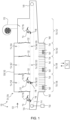
- a first exemplary embodiment of a cleaning system 110 for cleaning items 112 to be cleaned is shown with at least one cavity 114.
- the items to be cleaned 112 are shown as an example in this exemplary embodiment as a helmet 116 of personal protective equipment.
- the items to be cleaned 112 are accommodated on items to be cleaned 118, which are exemplary in a first exemplary embodiment in the Figures 2 , 3 and 4 are shown.
- Figure 2 a perspective view of a cleaning item carrier 118
- Figure 3 shows a sectional view through the cleaning item carrier 118 and a throwing nozzle 120, which will be explained in more detail below, in a section parallel to a transport direction 122 of the cleaning system 110
- Figure 4 shows the arrangement according to Figure 3 in a sectional view with a cutting plane perpendicular to the transport direction 122.
- the Figures 1 to 4 are explained together below.
- the cleaning system 110 includes, in addition to a plurality of the cleaning item carriers 118, a transport dishwasher 124.
- this transport dishwasher 124 is designed as an example of a belt dishwasher 126, also referred to as a belt transport dishwasher. She shows one Cleaning chamber 128 in the form of a cleaning tunnel 130.
- the cleaning tunnel 130 can be divided into several zones 134, also referred to as cleaning zones, in particular by separating curtains 132, with, in the exemplary embodiment shown, for example, a pre-clearing zone 136, a rinsing zone 138, also referred to as a washing zone, a final rinsing zone 140, also referred to as a final rinsing zone, and a drying zone 142 is provided.
- the final rinse zone 140 can, for example, be further divided into a pump rinse zone and a fresh water rinse zone. Another configuration of the zones 134 is also possible.
- the transport dishwasher 124 can be used, for example, as in Figure 1 shown, be designed as a tape transport machine 126, or, as described below with reference to Figure 6 shown in more detail, as a basket transport machine.
- at least one inlet or inlet area 146 can be provided, at which the items to be cleaned 112 are placed on the transport device 144, and at least one outlet or outlet area 148, at which the cleaned items to be cleaned 112 can be removed.
- the transport device 144 can accordingly comprise, for example, at least one belt and/or at least one link chain. Other configurations are also possible.
- the transport device 144 can, for example, include at least one drive 150, for example a motor, which can be controlled, for example, by a controller 152.
- the items to be cleaned 112 can be applied with at least one cleaning fluid 156, for example at least one cleaning liquid, by means of at least one application device 154.
- at least one pre-clearing zone nozzle system 158 can be provided in the pre-clearing zone 136, which, for example via an in Figure 1 Pump, not shown, and a line system, not shown, can be fed with cleaning fluid 156 from a pre-clearing tank 160.
- a rinsing zone nozzle system 162 can be provided, which can be fed with cleaning fluid 156 from a rinsing tank 164, also referred to as a washing tank, for example via a pump (also not shown) and a line system (also not shown).
- a rinsing tank 164 also referred to as a washing tank
- a pump also not shown
- a line system also not shown
- the final rinse zone 140 which can be designed in one piece or in several parts, for example at least one final rinse nozzle system 166, also referred to as a final rinse nozzle system, be provided, which can be fed with cleaning fluid 156 in the form of, for example, heated fresh water and / or with rinsing fluid from a rinsing tank 168, also referred to as a final rinsing tank.
- heaters 169 may be provided in tanks 160, 164 and 168.
- filter devices can also be provided in these tanks 160, 164 and 168, for example in order to purify the cleaning fluid 156 in a circulation operation.
- the tanks 160, 164 and 168 can be designed with a cascade overflow and/or a pumped cascade, so that, for example, there is a highest degree of purity in the final rinsing tank 168 and the lowest degree of purity in the pre-cleaning tank 160.
- the items to be cleaned 112 can then enter the drying zone 142, in which the items to be cleaned 112 can be supplied with warm air, for example via a fan 170, in order to accelerate the drying of the items to be cleaned 112.
- the outlet area 148 is downstream of the cleaning chamber 128 in the transport direction 122, so that the cleaned items 112 can be removed from the transport device 144 in the outlet area 148.
- the basic principle is that the loading device 154 is designed to be stationary, whereas the items to be cleaned 112 are moved in the transport direction 122 relative to this loading device 154.
- This cleaning principle can lead to challenges, particularly in the case of items 112 to be cleaned with at least one cavity 114, in that a sufficient amount of cleaning fluid 156 does not get into the cavity 114.
- the cavity 114 can in particular be an elongated cavity, for example at least one air duct, as in the example below Figure 6 will be explained in more detail.
- the cavity 114 and/or an inlet opening of this cavity 114 generally pass through the nozzles of the application device 154 too quickly for sufficient cleaning fluid to get into this cavity 114.
- the cavity 114 is in many cases covered by components of the transport device 144.
- the cleaning item carrier 118 has at least one base element 172, as well as at least one nozzle tube 174 connected to the base element 172.
- the nozzle tube 174 which can act as a movable cleaning nozzle and which can act as a movable cleaning nozzle, is therefore integrated into the movable cleaning item carrier 118 can provide a channel structure for fluid guidance.
- the nozzle tube 174 has at least one inlet opening 176 and at least one outlet nozzle 178, also as an outlet opening designated, on.
- the outlet nozzle 178 acts as a cleaning nozzle that is movable in the cleaning chamber 128 and transported by the transport device 144.
- the nozzle tube 174 has a collecting funnel 180 at its inlet opening 176, so that the nozzle tube 174 is tapered at least in sections in its interior.
- the inlet opening 176 can have a significantly larger diameter or equivalent diameter than the outlet nozzle 178.
- the nozzle tube 174 is designed such that the effective cross section on the side of the inlet opening 176 for capturing cleaning fluid 156 is significantly larger than the diameter or equivalent diameter of the Exit nozzle 178 and/or as a diameter of the at least one cavity 114 of the items to be cleaned 112 or an inlet opening of this cavity 114.
- the effective cross section for the penetration of Cleaning fluid 156 into the cavity 114 through the collecting funnel 180 is significantly increased.
- the nozzle tube 174 is accommodated in the base element 172 in such a way that the inlet opening 176 is arranged on an underside 182 of the base element 172, while the outlet nozzle 178 is arranged on an upper side 184 of the base element 172.
- the base element 172 can, for example, have a frame 186 on the top 184, which forms, for example, a completely or partially encircling frame 188.
- the items to be cleaned 112 can be fastened or clamped so that, for example, at least one opening of the cavity 114 comes into line with the outlet nozzle 178.
- the application device 154 can, for example, as in the Figures 3 and 4 can be seen, the at least one throwing nozzle 120, which, for example, is part of a lower nozzle system of the transport dishwasher 124 according to Figure 1 can be, include.
- This throwing nozzle 120 can, for example, as in the Figures 3 and 4 recognizable, oriented upwards.
- cleaning fluid 156 emerging from the throwing nozzle 120 can enter the collecting funnel 180 and, due to its momentum on the upper side 184, can emerge from the outlet nozzle 178 and be injected into the cavity 114 of the items to be cleaned 112 become.
- further exposure can occur from one or more spatial directions from other nozzles of the exposure device 154, so that, in addition to the cavity 114, at least one surface of the items to be cleaned 112 can also be cleaned by cleaning fluid 156.
- the arrangement of the inlet opening 176 on the underside 182 of the base element 172 is fundamentally preferable, since cleaning fluid 156 can then drain downwards again after the cavity 114 has been acted upon, driven by its gravity.
- the inlet opening 176 can also be arranged on at least one side wall of the base element 172, for example on at least one long side, and/or also on the top 184.
- one or more inlet openings 176 can be provided.
- the inlet opening 176 can be circular, for example.
- an embodiment may also be possible in which, for example, an extension in the transport direction 122 is longer than transverse to the transport direction 122, so that cleaning fluid 156 is captured by the collecting funnel 180 over a longer distance. This allows the exposure time to be extended.
- the at least one nozzle tube 174 can, for example, penetrate the base element 172 and/or can be held in the base element 172 or on the base element 172 in another way.
- the base element 172 as in Figure 2 recognizable, be designed as a grid 190 and can have a plurality of grid struts 192, which connect the nozzle tube 174 to the frame 188. In this way, cleaning fluid can drain downward through the base element 172.
- the transport device 144 of the transport dishwasher 124 can be designed in particular as a belt or as a link chain.
- the base element 172 can, for example, be integrated into the transport device 144 and/or connectable to the transport device 144, preferably reversibly.
- the base element 172 can be designed as a chain link of a link chain, for example with holes through which band rods 194 of the transport device are guided, which then extend further to both sides.
- the cleaning item carrier 118 can be designed in one piece or in several parts.
- the frame 186 can be completely or partially removable from the base element 172.
- the removable part can be connected to the items to be cleaned 112 and can be removed from the transport device 144 in the outlet area 148.
- the transport dishwasher 124 is designed as an example of a belt dishwasher 126.
- the cleaning item carrier 118 can accordingly be designed, for example, as a device which can be integrated into a belt or a link chain of the transport device 144, for example as a chain link, and / or which can be connected to the belt or the link chain of the transport device 144, for example reversibly, for example through a positive and/or non-positive connection.
- the cleaning item carrier 118 can also be hooked or snapped into this belt, for example.
- the transport dishwasher 124 can also be designed in a different way, for example as a rack transport dishwasher 196. This is exemplified in FIGS Figures 5 and 6 shown.
- FIG. 5 This shows Figure 5 , analogous to Figure 1 , an exemplary embodiment of a transport dishwasher 124 designed as a basket transport dishwasher 196 in a sectional view with a cutting plane parallel to a transport direction 122.
- Figure 6 accordingly shows a sectional view through a cleaning item carrier 118 designed as a cleaning basket 198 for use in the basket transport dishwasher 196 according to Figure 5 . Both figures are described together below.
- the cleaning system 110 has a transport dishwasher 124 and a plurality of cleaning item carriers 118.
- the transport dishwasher 124 is designed as a basket transport dishwasher 196, and the cleaning item carriers 118 are designed as cleaning baskets 198.
- the transport device 144 can be designed in particular as a conveyor belt for the cleaning baskets 198, onto which the cleaning baskets 198 can be placed. Otherwise, the possible configurations and elements of the transport dishwasher 124 can largely be referred to the description of Figure 1 to get expelled.
- FIG. 6 an embodiment of a cleaning basket 198 is shown in a sectional view.
- the cleaning basket 198 in turn comprises a base element 172, which can be designed, for example, as a basket base.
- a plurality of openings 200 can be provided in the base element 172, through which cleaning fluid can drain from the cleaning basket 198.
- at least one nozzle tube 174 is again provided, which can, for example, have an inlet opening 176 on an underside 182 of the cleaning item carrier 118 and/or the base element 172.
- a collecting funnel 180 and an outlet nozzle 178 are also provided, where on the description of the Figures 2 to 4 can be referred.
- An analogous design to these figures is also in Figure 6 at least possible.
- the items to be cleaned include 112 items of personal protective equipment.
- a helmet 116 is shown here, which can have a respiratory protection function.
- This helmet 116 has at least one cavity 114, which in Figure 6 is shown in sectional view.
- This cavity 114 is designed as an air duct 202, also referred to as a breathing air duct.
- This air duct 202 whereby one or more such channels can be provided, can be set up to supply inhaled air and/or to remove exhaled air.
- At least one frame 186 can in turn be provided on the base element 172.
- this frame 186 can, for example, form or comprise a frame 188, which can, for example, form a basket wall of the cleaning basket 198.
- the frame 186 can, for example, form or include at least one holder 204 for the items 112 to be cleaned.
- the items to be cleaned 112 can be fixed in such a way that at least one inlet opening 206 of the cavity 114, for example of the air duct 202, comes into line with the outlet nozzle 178, as in Figure 6 recognizable.
- the cavity 114 can also have at least one outlet opening 210, for example on an end face 208 of the helmet 116.
- the injected cleaning fluid can exit the cavity 114 again from this outlet opening 210 or from the inlet opening 206.
- the cavity 114 may generally include at least one opening.
- the items to be cleaned 112 can also be fixed in another way.
- a strap 212 of the helmet 116 can be held by the holder 204.
- the helmet 116 can also have, for example, at least one visor 214, which can be held in a certain position for cleaning, for example.
- the frame 186 can have at least one holder 216 for the visor 214, which holds the visor 214 during cleaning can hold in a predetermined position, for example a predetermined angular position.
- FIG 7 a schematic flowchart of an exemplary embodiment of a method for cleaning items to be cleaned 112 with at least one cavity 114 is shown.
- the method includes the use of a cleaning system 110 according to the invention, for example according to Figure 1 or according to Figure 5 . Accordingly, reference can largely be made to the above description of these figures for possible configurations.
- the method includes receiving the items to be cleaned 112 in the items to be cleaned 118, such that the cavity 114 of the items to be cleaned 112 can be acted upon by the at least one cleaning fluid 156 by means of the outlet nozzle 178 of the nozzle tube 174 (step 218).
- this can be done by bringing at least one inlet opening 206 of the cavity 114 into line with the outlet nozzle 178.
- the method includes according to Figure 7 a transport of the cleaning item carrier 118 by means of the transport device 144 through the cleaning chamber 128 (step 220).
- the method includes according to Figure 7 applying the at least one cleaning fluid 156 to the items to be cleaned 112 by means of the applying device 154 (step 222).
- This application takes place in such a way that in at least one position of the cleaning item carrier 118 relative to the at least one throwing nozzle 120, cleaning fluid 156 emerging from the throwing nozzle 120 enters the collecting funnel 180 of the nozzle tube 174, in particular is injected.
- the application takes place in such a way that this cleaning fluid 156 passes through the nozzle tube 174 and enters, in particular is injected, from the outlet nozzle 178 of the nozzle tube 174 into the cavity 114 of the item to be cleaned 112. This loading can take place in particular during a movement of the transport device 144.
Landscapes
- Health & Medical Sciences (AREA)
- General Health & Medical Sciences (AREA)
- Veterinary Medicine (AREA)
- Public Health (AREA)
- Animal Behavior & Ethology (AREA)
- Life Sciences & Earth Sciences (AREA)
- Epidemiology (AREA)
- General Chemical & Material Sciences (AREA)
- Chemical Kinetics & Catalysis (AREA)
- Chemical & Material Sciences (AREA)
- Mechanical Engineering (AREA)
- Engineering & Computer Science (AREA)
- Cleaning By Liquid Or Steam (AREA)
- Washing And Drying Of Tableware (AREA)
- Cleaning In General (AREA)
Applications Claiming Priority (2)
| Application Number | Priority Date | Filing Date | Title |
|---|---|---|---|
| DE102019219094.4A DE102019219094B3 (de) | 2019-12-06 | 2019-12-06 | Reinigung von Reinigungsgut mit mindestens einem Hohlraum in einer Transportspülmaschine |
| PCT/EP2020/084601 WO2021110897A1 (de) | 2019-12-06 | 2020-12-04 | Reinigung von reinigungsgut mit mindestens einem hohlraum in einer transportspülmaschine |
Publications (2)
| Publication Number | Publication Date |
|---|---|
| EP4069441A1 EP4069441A1 (de) | 2022-10-12 |
| EP4069441B1 true EP4069441B1 (de) | 2024-01-31 |
Family
ID=73740397
Family Applications (1)
| Application Number | Title | Priority Date | Filing Date |
|---|---|---|---|
| EP20820381.0A Active EP4069441B1 (de) | 2019-12-06 | 2020-12-04 | Reinigung von reinigungsgut mit mindestens einem hohlraum in einer transportspülmaschine |
Country Status (11)
| Country | Link |
|---|---|
| US (1) | US12275043B2 (pl) |
| EP (1) | EP4069441B1 (pl) |
| KR (1) | KR20220110256A (pl) |
| CN (1) | CN114761147A (pl) |
| AU (1) | AU2020398682B2 (pl) |
| CA (1) | CA3159871A1 (pl) |
| DE (1) | DE102019219094B3 (pl) |
| DK (1) | DK4069441T3 (pl) |
| ES (1) | ES2977172T3 (pl) |
| PL (1) | PL4069441T3 (pl) |
| WO (1) | WO2021110897A1 (pl) |
Families Citing this family (4)
| Publication number | Priority date | Publication date | Assignee | Title |
|---|---|---|---|---|
| DE102020133780B4 (de) | 2020-12-16 | 2025-01-09 | Miele & Cie. Kg | Haltesystem zum Aufnehmen eines Helmes und Verfahren zum Trocknen eines Helmes |
| US12440396B2 (en) | 2022-03-30 | 2025-10-14 | Able Innovations Inc. | Transfer device with platform plate having two-sided functionality and treatment system |
| US12440411B2 (en) * | 2022-03-30 | 2025-10-14 | Able Innovations Inc. | Transfer device with platform plate having two-sided functionality and treatment system |
| CN117258012B (zh) * | 2023-11-16 | 2024-05-07 | 四川大学华西医院 | 一种带有即时清洁功能的外科手术护理工具箱 |
Family Cites Families (17)
| Publication number | Priority date | Publication date | Assignee | Title |
|---|---|---|---|---|
| DE1174169B (de) | 1961-10-24 | 1964-07-16 | Walter Siepermann | Reinigungs- und Desinfektionsvorrichtung fuer Atemschutzmasken |
| CH530935A (de) * | 1971-03-12 | 1972-11-30 | Hildebrand Ed Ing Ag | Korb für Reinigungsmaschine |
| GB1432368A (en) * | 1972-07-12 | 1976-04-14 | Ethicon Inc | Apparatus for washing and decontaminating articles |
| DE2712020C2 (de) * | 1977-03-18 | 1983-12-22 | MMM Münchner Medizin Mechanik GmbH, 8000 München | Dekontaminationsanlage für chirurgische Instrumente, wiederverwendbare Krankenhauspflege- und Behandlungsutensilien und dergleichen |
| EP0935687B1 (de) * | 1996-11-02 | 2001-06-13 | Miele & Cie. GmbH & Co. | Trommelwaschmaschine |
| DE29822172U1 (de) * | 1998-12-11 | 1999-02-11 | Odenwaldwerke Rittersbach GmbH Fahrzeugbau und Katastrophenschutzsysteme, 74834 Elztal | Kabinensystem zum Behandeln von Schutzanzügen für Katastrophenfälle |
| ATE264934T1 (de) * | 1999-09-30 | 2004-05-15 | Miele & Cie | Wäschebehandlungsmaschine |
| DE20003743U1 (de) * | 2000-02-29 | 2000-11-23 | Hoen, Rainer, 74838 Limbach | Behandlungssystem für Vollschutzanzüge |
| DE20003744U1 (de) * | 2000-02-29 | 2000-07-06 | Hoen, Rainer, 74838 Limbach | Vorrichtung zum Reinigen, Desinfizieren, Dekontaminieren und Trocknen von Atemschutzmasken |
| DE10020835A1 (de) * | 2000-04-28 | 2001-11-08 | Axel Rother | Vorrichtung zur Behandlung von Atemschutzmasken |
| DE102005033618B3 (de) * | 2005-07-19 | 2006-11-16 | Rainer Hoen | Vorrichtung zur Reinigung von Atemschutzmasken |
| DE102007009936B4 (de) * | 2007-03-01 | 2011-02-03 | Rainer Hoen | Reinigungsvorrichtung für Preßluftatmer |
| DE102007012768B4 (de) * | 2007-03-16 | 2009-01-15 | Rainer Hoen | Verfahren und Vorrichtung zum Reinigen von Lungenautomaten |
| DE102010029221A1 (de) * | 2010-05-21 | 2011-11-24 | Meiko Maschinenbau Gmbh & Co. Kg | Vorrichtung zur Reinigung von Atemgeräten |
| DE102011003782A1 (de) * | 2011-02-08 | 2012-08-09 | Meiko Maschinenbau Gmbh & Co. Kg | Reinigungsvorrichtung zur Reinigung von Reinigungsgut |
| DE102014209765A1 (de) * | 2014-05-22 | 2015-11-26 | Meiko Maschinenbau Gmbh & Co. Kg | Reinigungsvorrichtung mit verbesserter Trocknung |
| JP6747675B2 (ja) * | 2016-12-29 | 2020-08-26 | 株式会社マスダック | カップ洗浄装置 |
-
2019
- 2019-12-06 DE DE102019219094.4A patent/DE102019219094B3/de active Active
-
2020
- 2020-12-04 AU AU2020398682A patent/AU2020398682B2/en active Active
- 2020-12-04 DK DK20820381.0T patent/DK4069441T3/da active
- 2020-12-04 ES ES20820381T patent/ES2977172T3/es active Active
- 2020-12-04 WO PCT/EP2020/084601 patent/WO2021110897A1/de not_active Ceased
- 2020-12-04 CA CA3159871A patent/CA3159871A1/en active Pending
- 2020-12-04 PL PL20820381.0T patent/PL4069441T3/pl unknown
- 2020-12-04 EP EP20820381.0A patent/EP4069441B1/de active Active
- 2020-12-04 KR KR1020227022581A patent/KR20220110256A/ko active Pending
- 2020-12-04 US US17/782,881 patent/US12275043B2/en active Active
- 2020-12-04 CN CN202080084600.4A patent/CN114761147A/zh active Pending
Also Published As
| Publication number | Publication date |
|---|---|
| ES2977172T3 (es) | 2024-08-20 |
| CA3159871A1 (en) | 2021-06-10 |
| DK4069441T3 (da) | 2024-02-26 |
| CN114761147A (zh) | 2022-07-15 |
| DE102019219094B3 (de) | 2020-12-31 |
| PL4069441T3 (pl) | 2024-06-10 |
| KR20220110256A (ko) | 2022-08-05 |
| US20230030171A1 (en) | 2023-02-02 |
| US12275043B2 (en) | 2025-04-15 |
| EP4069441A1 (de) | 2022-10-12 |
| AU2020398682A1 (en) | 2022-06-23 |
| WO2021110897A1 (de) | 2021-06-10 |
| AU2020398682B2 (en) | 2026-02-26 |
Similar Documents
| Publication | Publication Date | Title |
|---|---|---|
| EP4069441B1 (de) | Reinigung von reinigungsgut mit mindestens einem hohlraum in einer transportspülmaschine | |
| EP2571632B3 (de) | Vorrichtung zur reinigung von atemgeräten | |
| DE102016012488B4 (de) | Reinigungs-, Desinfektions- und Trocknungs-Anlage | |
| EP2743087B2 (de) | Druckmaschine mit Verkleidung | |
| WO2021037834A1 (de) | Reinigungskorb zur reinigung von atemgerät | |
| DE19945500A1 (de) | Verfahren und Vorrichtung zum Entkeimen von Behältern in einer Füllmaschine | |
| DE102005033618B3 (de) | Vorrichtung zur Reinigung von Atemschutzmasken | |
| DE10020835A1 (de) | Vorrichtung zur Behandlung von Atemschutzmasken | |
| DE202020003389U1 (de) | Anordnung zur Desinfektion von Touchscreens mittels UV-LED-Strahlen | |
| EP1297748B1 (de) | Verfahren und Vorrichtung zur Vorbereitung von geschlachtetem Geflügel auf das Rupfen | |
| DE102011054683A1 (de) | Trocknungsvorrichtung für Behälter und Verfahren zum Reinigen einer solchen Trocknungsvorrichtung | |
| DE3321195C2 (pl) | ||
| DE102014015909B4 (de) | Wartungsvorrichtung und Verfahren zum Warten eines Kreislaufatemgerätes | |
| AT511898A1 (de) | Reinigungsmaschine zum reinigen industriell gefertigter bauteile | |
| DE29520880U1 (de) | Trockenreinigungsanlage von Werkstücken in der mechanischen Fertigung | |
| DE102012003557A1 (de) | Einrichtung und Verfahren zur hygienischen Aufbereitung von Gegenständen | |
| EP3936242A1 (de) | Verfahren und ein reinigungssystem zur reinigung von atemgerät | |
| DE102017106756B3 (de) | Verfahren und Anlage zum Aufbereiten von Rähmchen | |
| DE3423529A1 (de) | Verfahren und vorrichtung zum verhindern des luftaustritts aus der auslassoeffnung einer durchlaufdekontaminationsvorrichtung | |
| EP3875880B1 (de) | Vorrichtung zur reinigung eines heizungskörpers sowie verfahren hierzu | |
| DE102004038697A1 (de) | Textilmaschine mit Luftförderer und Filtereinrichtung | |
| EP1895242A1 (de) | Verfahren und Vorrichtung zum Beseitigen von belasteter Luft aus Räumen mittels Luftvorhang | |
| DE29923443U1 (de) | Vorrichtung zum Entkeimen von Behältern in einer Füllmaschine | |
| DE102024123942A1 (de) | Transfervorrichtung zum kontaminationsfreien Transport von Behältern in einer Vorrichtung zum Behandeln von Behältern | |
| EP0509536A2 (de) | Verfahren und Vorrichtung zum Regenerieren schadstoffbelasteter Teile |
Legal Events
| Date | Code | Title | Description |
|---|---|---|---|
| STAA | Information on the status of an ep patent application or granted ep patent |
Free format text: STATUS: UNKNOWN |
|
| STAA | Information on the status of an ep patent application or granted ep patent |
Free format text: STATUS: THE INTERNATIONAL PUBLICATION HAS BEEN MADE |
|
| PUAI | Public reference made under article 153(3) epc to a published international application that has entered the european phase |
Free format text: ORIGINAL CODE: 0009012 |
|
| STAA | Information on the status of an ep patent application or granted ep patent |
Free format text: STATUS: REQUEST FOR EXAMINATION WAS MADE |
|
| 17P | Request for examination filed |
Effective date: 20220628 |
|
| AK | Designated contracting states |
Kind code of ref document: A1 Designated state(s): AL AT BE BG CH CY CZ DE DK EE ES FI FR GB GR HR HU IE IS IT LI LT LU LV MC MK MT NL NO PL PT RO RS SE SI SK SM TR |
|
| DAV | Request for validation of the european patent (deleted) | ||
| DAX | Request for extension of the european patent (deleted) | ||
| REG | Reference to a national code |
Ref legal event code: R079 Ipc: A61L0002180000 Ref country code: DE Ref legal event code: R079 Ref document number: 502020006897 Country of ref document: DE Free format text: PREVIOUS MAIN CLASS: B08B0003020000 Ipc: A61L0002180000 |
|
| GRAP | Despatch of communication of intention to grant a patent |
Free format text: ORIGINAL CODE: EPIDOSNIGR1 |
|
| STAA | Information on the status of an ep patent application or granted ep patent |
Free format text: STATUS: GRANT OF PATENT IS INTENDED |
|
| RIC1 | Information provided on ipc code assigned before grant |
Ipc: B08B 13/00 20060101ALI20230613BHEP Ipc: B08B 3/02 20060101ALI20230613BHEP Ipc: A61L 2/18 20060101AFI20230613BHEP |
|
| INTG | Intention to grant announced |
Effective date: 20230629 |
|
| P01 | Opt-out of the competence of the unified patent court (upc) registered |
Effective date: 20230731 |
|
| GRAS | Grant fee paid |
Free format text: ORIGINAL CODE: EPIDOSNIGR3 |
|
| GRAA | (expected) grant |
Free format text: ORIGINAL CODE: 0009210 |
|
| STAA | Information on the status of an ep patent application or granted ep patent |
Free format text: STATUS: THE PATENT HAS BEEN GRANTED |
|
| AK | Designated contracting states |
Kind code of ref document: B1 Designated state(s): AL AT BE BG CH CY CZ DE DK EE ES FI FR GB GR HR HU IE IS IT LI LT LU LV MC MK MT NL NO PL PT RO RS SE SI SK SM TR |
|
| REG | Reference to a national code |
Ref country code: GB Ref legal event code: FG4D Free format text: NOT ENGLISH Ref country code: CH Ref legal event code: EP |
|
| REG | Reference to a national code |
Ref country code: DE Ref legal event code: R096 Ref document number: 502020006897 Country of ref document: DE |
|
| REG | Reference to a national code |
Ref country code: DK Ref legal event code: T3 Effective date: 20240223 |
|
| REG | Reference to a national code |
Ref country code: IE Ref legal event code: FG4D Free format text: LANGUAGE OF EP DOCUMENT: GERMAN |
|
| REG | Reference to a national code |
Ref country code: NL Ref legal event code: FP |
|
| REG | Reference to a national code |
Ref country code: SE Ref legal event code: TRGR |
|
| REG | Reference to a national code |
Ref country code: LT Ref legal event code: MG9D |
|
| PG25 | Lapsed in a contracting state [announced via postgrant information from national office to epo] |
Ref country code: IS Free format text: LAPSE BECAUSE OF FAILURE TO SUBMIT A TRANSLATION OF THE DESCRIPTION OR TO PAY THE FEE WITHIN THE PRESCRIBED TIME-LIMIT Effective date: 20240531 |
|
| PG25 | Lapsed in a contracting state [announced via postgrant information from national office to epo] |
Ref country code: LT Free format text: LAPSE BECAUSE OF FAILURE TO SUBMIT A TRANSLATION OF THE DESCRIPTION OR TO PAY THE FEE WITHIN THE PRESCRIBED TIME-LIMIT Effective date: 20240131 |
|
| PG25 | Lapsed in a contracting state [announced via postgrant information from national office to epo] |
Ref country code: GR Free format text: LAPSE BECAUSE OF FAILURE TO SUBMIT A TRANSLATION OF THE DESCRIPTION OR TO PAY THE FEE WITHIN THE PRESCRIBED TIME-LIMIT Effective date: 20240501 |
|
| PG25 | Lapsed in a contracting state [announced via postgrant information from national office to epo] |
Ref country code: RS Free format text: LAPSE BECAUSE OF FAILURE TO SUBMIT A TRANSLATION OF THE DESCRIPTION OR TO PAY THE FEE WITHIN THE PRESCRIBED TIME-LIMIT Effective date: 20240430 Ref country code: HR Free format text: LAPSE BECAUSE OF FAILURE TO SUBMIT A TRANSLATION OF THE DESCRIPTION OR TO PAY THE FEE WITHIN THE PRESCRIBED TIME-LIMIT Effective date: 20240131 |
|
| PG25 | Lapsed in a contracting state [announced via postgrant information from national office to epo] |
Ref country code: RS Free format text: LAPSE BECAUSE OF FAILURE TO SUBMIT A TRANSLATION OF THE DESCRIPTION OR TO PAY THE FEE WITHIN THE PRESCRIBED TIME-LIMIT Effective date: 20240430 Ref country code: NO Free format text: LAPSE BECAUSE OF FAILURE TO SUBMIT A TRANSLATION OF THE DESCRIPTION OR TO PAY THE FEE WITHIN THE PRESCRIBED TIME-LIMIT Effective date: 20240430 Ref country code: LT Free format text: LAPSE BECAUSE OF FAILURE TO SUBMIT A TRANSLATION OF THE DESCRIPTION OR TO PAY THE FEE WITHIN THE PRESCRIBED TIME-LIMIT Effective date: 20240131 Ref country code: IS Free format text: LAPSE BECAUSE OF FAILURE TO SUBMIT A TRANSLATION OF THE DESCRIPTION OR TO PAY THE FEE WITHIN THE PRESCRIBED TIME-LIMIT Effective date: 20240531 Ref country code: HR Free format text: LAPSE BECAUSE OF FAILURE TO SUBMIT A TRANSLATION OF THE DESCRIPTION OR TO PAY THE FEE WITHIN THE PRESCRIBED TIME-LIMIT Effective date: 20240131 Ref country code: GR Free format text: LAPSE BECAUSE OF FAILURE TO SUBMIT A TRANSLATION OF THE DESCRIPTION OR TO PAY THE FEE WITHIN THE PRESCRIBED TIME-LIMIT Effective date: 20240501 Ref country code: FI Free format text: LAPSE BECAUSE OF FAILURE TO SUBMIT A TRANSLATION OF THE DESCRIPTION OR TO PAY THE FEE WITHIN THE PRESCRIBED TIME-LIMIT Effective date: 20240131 Ref country code: BG Free format text: LAPSE BECAUSE OF FAILURE TO SUBMIT A TRANSLATION OF THE DESCRIPTION OR TO PAY THE FEE WITHIN THE PRESCRIBED TIME-LIMIT Effective date: 20240131 |
|
| PG25 | Lapsed in a contracting state [announced via postgrant information from national office to epo] |
Ref country code: PT Free format text: LAPSE BECAUSE OF FAILURE TO SUBMIT A TRANSLATION OF THE DESCRIPTION OR TO PAY THE FEE WITHIN THE PRESCRIBED TIME-LIMIT Effective date: 20240531 |
|
| REG | Reference to a national code |
Ref country code: ES Ref legal event code: FG2A Ref document number: 2977172 Country of ref document: ES Kind code of ref document: T3 Effective date: 20240820 |
|
| PG25 | Lapsed in a contracting state [announced via postgrant information from national office to epo] |
Ref country code: PT Free format text: LAPSE BECAUSE OF FAILURE TO SUBMIT A TRANSLATION OF THE DESCRIPTION OR TO PAY THE FEE WITHIN THE PRESCRIBED TIME-LIMIT Effective date: 20240531 Ref country code: LV Free format text: LAPSE BECAUSE OF FAILURE TO SUBMIT A TRANSLATION OF THE DESCRIPTION OR TO PAY THE FEE WITHIN THE PRESCRIBED TIME-LIMIT Effective date: 20240131 |
|
| PG25 | Lapsed in a contracting state [announced via postgrant information from national office to epo] |
Ref country code: SM Free format text: LAPSE BECAUSE OF FAILURE TO SUBMIT A TRANSLATION OF THE DESCRIPTION OR TO PAY THE FEE WITHIN THE PRESCRIBED TIME-LIMIT Effective date: 20240131 |
|
| PG25 | Lapsed in a contracting state [announced via postgrant information from national office to epo] |
Ref country code: EE Free format text: LAPSE BECAUSE OF FAILURE TO SUBMIT A TRANSLATION OF THE DESCRIPTION OR TO PAY THE FEE WITHIN THE PRESCRIBED TIME-LIMIT Effective date: 20240131 Ref country code: CZ Free format text: LAPSE BECAUSE OF FAILURE TO SUBMIT A TRANSLATION OF THE DESCRIPTION OR TO PAY THE FEE WITHIN THE PRESCRIBED TIME-LIMIT Effective date: 20240131 |
|
| PG25 | Lapsed in a contracting state [announced via postgrant information from national office to epo] |
Ref country code: SK Free format text: LAPSE BECAUSE OF FAILURE TO SUBMIT A TRANSLATION OF THE DESCRIPTION OR TO PAY THE FEE WITHIN THE PRESCRIBED TIME-LIMIT Effective date: 20240131 |
|
| PG25 | Lapsed in a contracting state [announced via postgrant information from national office to epo] |
Ref country code: SM Free format text: LAPSE BECAUSE OF FAILURE TO SUBMIT A TRANSLATION OF THE DESCRIPTION OR TO PAY THE FEE WITHIN THE PRESCRIBED TIME-LIMIT Effective date: 20240131 Ref country code: SK Free format text: LAPSE BECAUSE OF FAILURE TO SUBMIT A TRANSLATION OF THE DESCRIPTION OR TO PAY THE FEE WITHIN THE PRESCRIBED TIME-LIMIT Effective date: 20240131 Ref country code: RO Free format text: LAPSE BECAUSE OF FAILURE TO SUBMIT A TRANSLATION OF THE DESCRIPTION OR TO PAY THE FEE WITHIN THE PRESCRIBED TIME-LIMIT Effective date: 20240131 Ref country code: EE Free format text: LAPSE BECAUSE OF FAILURE TO SUBMIT A TRANSLATION OF THE DESCRIPTION OR TO PAY THE FEE WITHIN THE PRESCRIBED TIME-LIMIT Effective date: 20240131 Ref country code: CZ Free format text: LAPSE BECAUSE OF FAILURE TO SUBMIT A TRANSLATION OF THE DESCRIPTION OR TO PAY THE FEE WITHIN THE PRESCRIBED TIME-LIMIT Effective date: 20240131 |
|
| REG | Reference to a national code |
Ref country code: DE Ref legal event code: R097 Ref document number: 502020006897 Country of ref document: DE |
|
| PLBE | No opposition filed within time limit |
Free format text: ORIGINAL CODE: 0009261 |
|
| STAA | Information on the status of an ep patent application or granted ep patent |
Free format text: STATUS: NO OPPOSITION FILED WITHIN TIME LIMIT |
|
| 26N | No opposition filed |
Effective date: 20241101 |
|
| PG25 | Lapsed in a contracting state [announced via postgrant information from national office to epo] |
Ref country code: SI Free format text: LAPSE BECAUSE OF FAILURE TO SUBMIT A TRANSLATION OF THE DESCRIPTION OR TO PAY THE FEE WITHIN THE PRESCRIBED TIME-LIMIT Effective date: 20240131 |
|
| PG25 | Lapsed in a contracting state [announced via postgrant information from national office to epo] |
Ref country code: MC Free format text: LAPSE BECAUSE OF FAILURE TO SUBMIT A TRANSLATION OF THE DESCRIPTION OR TO PAY THE FEE WITHIN THE PRESCRIBED TIME-LIMIT Effective date: 20240131 |
|
| PG25 | Lapsed in a contracting state [announced via postgrant information from national office to epo] |
Ref country code: LU Free format text: LAPSE BECAUSE OF NON-PAYMENT OF DUE FEES Effective date: 20241204 |
|
| REG | Reference to a national code |
Ref country code: BE Ref legal event code: MM Effective date: 20241231 |
|
| PG25 | Lapsed in a contracting state [announced via postgrant information from national office to epo] |
Ref country code: BE Free format text: LAPSE BECAUSE OF NON-PAYMENT OF DUE FEES Effective date: 20241231 |
|
| PG25 | Lapsed in a contracting state [announced via postgrant information from national office to epo] |
Ref country code: IE Free format text: LAPSE BECAUSE OF NON-PAYMENT OF DUE FEES Effective date: 20241204 |
|
| REG | Reference to a national code |
Ref country code: CH Ref legal event code: U11 Free format text: ST27 STATUS EVENT CODE: U-0-0-U10-U11 (AS PROVIDED BY THE NATIONAL OFFICE) Effective date: 20260101 |
|
| PGFP | Annual fee paid to national office [announced via postgrant information from national office to epo] |
Ref country code: GB Payment date: 20251229 Year of fee payment: 6 |
|
| PGFP | Annual fee paid to national office [announced via postgrant information from national office to epo] |
Ref country code: AT Payment date: 20251222 Year of fee payment: 6 |
|
| PGFP | Annual fee paid to national office [announced via postgrant information from national office to epo] |
Ref country code: DK Payment date: 20251223 Year of fee payment: 6 |
|
| PGFP | Annual fee paid to national office [announced via postgrant information from national office to epo] |
Ref country code: NL Payment date: 20251223 Year of fee payment: 6 Ref country code: FR Payment date: 20251223 Year of fee payment: 6 |
|
| PGFP | Annual fee paid to national office [announced via postgrant information from national office to epo] |
Ref country code: TR Payment date: 20251201 Year of fee payment: 6 |
|
| PGFP | Annual fee paid to national office [announced via postgrant information from national office to epo] |
Ref country code: SE Payment date: 20251223 Year of fee payment: 6 |
|
| PGFP | Annual fee paid to national office [announced via postgrant information from national office to epo] |
Ref country code: PL Payment date: 20251125 Year of fee payment: 6 |
|
| PG25 | Lapsed in a contracting state [announced via postgrant information from national office to epo] |
Ref country code: CY Free format text: LAPSE BECAUSE OF FAILURE TO SUBMIT A TRANSLATION OF THE DESCRIPTION OR TO PAY THE FEE WITHIN THE PRESCRIBED TIME-LIMIT; INVALID AB INITIO Effective date: 20201204 |
|
| PGFP | Annual fee paid to national office [announced via postgrant information from national office to epo] |
Ref country code: ES Payment date: 20260102 Year of fee payment: 6 |
|
| PGFP | Annual fee paid to national office [announced via postgrant information from national office to epo] |
Ref country code: DE Payment date: 20251230 Year of fee payment: 6 |
|
| PGFP | Annual fee paid to national office [announced via postgrant information from national office to epo] |
Ref country code: IT Payment date: 20251229 Year of fee payment: 6 |
|
| PGFP | Annual fee paid to national office [announced via postgrant information from national office to epo] |
Ref country code: CH Payment date: 20260101 Year of fee payment: 6 |