EP4069394B1 - Verfahren und anlage zum destillieren einer flüssigkeit - Google Patents
Verfahren und anlage zum destillieren einer flüssigkeit Download PDFInfo
- Publication number
- EP4069394B1 EP4069394B1 EP20758108.3A EP20758108A EP4069394B1 EP 4069394 B1 EP4069394 B1 EP 4069394B1 EP 20758108 A EP20758108 A EP 20758108A EP 4069394 B1 EP4069394 B1 EP 4069394B1
- Authority
- EP
- European Patent Office
- Prior art keywords
- liquid
- distillation
- intermediate container
- distillation column
- container
- Prior art date
- Legal status (The legal status is an assumption and is not a legal conclusion. Google has not performed a legal analysis and makes no representation as to the accuracy of the status listed.)
- Active
Links
Images


Classifications
-
- B—PERFORMING OPERATIONS; TRANSPORTING
- B01—PHYSICAL OR CHEMICAL PROCESSES OR APPARATUS IN GENERAL
- B01D—SEPARATION
- B01D3/00—Distillation or related exchange processes in which liquids are contacted with gaseous media, e.g. stripping
- B01D3/10—Vacuum distillation
- B01D3/108—Vacuum distillation using a vacuum lock for removing the concentrate during distillation
-
- B—PERFORMING OPERATIONS; TRANSPORTING
- B01—PHYSICAL OR CHEMICAL PROCESSES OR APPARATUS IN GENERAL
- B01D—SEPARATION
- B01D3/00—Distillation or related exchange processes in which liquids are contacted with gaseous media, e.g. stripping
-
- B—PERFORMING OPERATIONS; TRANSPORTING
- B01—PHYSICAL OR CHEMICAL PROCESSES OR APPARATUS IN GENERAL
- B01D—SEPARATION
- B01D1/00—Evaporating
- B01D1/0011—Heating features
- B01D1/0041—Use of fluids
- B01D1/0052—Use of a liquid transfer medium or intermediate fluid, e.g. bain-marie
-
- B—PERFORMING OPERATIONS; TRANSPORTING
- B01—PHYSICAL OR CHEMICAL PROCESSES OR APPARATUS IN GENERAL
- B01D—SEPARATION
- B01D1/00—Evaporating
- B01D1/0064—Feeding of liquid into an evaporator
- B01D1/0076—Maintaining the liquid in the evaporator at a constant level
-
- B—PERFORMING OPERATIONS; TRANSPORTING
- B01—PHYSICAL OR CHEMICAL PROCESSES OR APPARATUS IN GENERAL
- B01D—SEPARATION
- B01D3/00—Distillation or related exchange processes in which liquids are contacted with gaseous media, e.g. stripping
- B01D3/02—Distillation or related exchange processes in which liquids are contacted with gaseous media, e.g. stripping in boilers or stills
-
- B—PERFORMING OPERATIONS; TRANSPORTING
- B01—PHYSICAL OR CHEMICAL PROCESSES OR APPARATUS IN GENERAL
- B01D—SEPARATION
- B01D3/00—Distillation or related exchange processes in which liquids are contacted with gaseous media, e.g. stripping
- B01D3/42—Regulation; Control
-
- B—PERFORMING OPERATIONS; TRANSPORTING
- B01—PHYSICAL OR CHEMICAL PROCESSES OR APPARATUS IN GENERAL
- B01D—SEPARATION
- B01D5/00—Condensation of vapours; Recovering volatile solvents by condensation
- B01D5/0057—Condensation of vapours; Recovering volatile solvents by condensation in combination with other processes
- B01D5/006—Condensation of vapours; Recovering volatile solvents by condensation in combination with other processes with evaporation or distillation
-
- B—PERFORMING OPERATIONS; TRANSPORTING
- B01—PHYSICAL OR CHEMICAL PROCESSES OR APPARATUS IN GENERAL
- B01D—SEPARATION
- B01D5/00—Condensation of vapours; Recovering volatile solvents by condensation
- B01D5/0078—Condensation of vapours; Recovering volatile solvents by condensation characterised by auxiliary systems or arrangements
- B01D5/009—Collecting, removing and/or treatment of the condensate
Definitions
- the invention relates to a method for distilling a liquid from a dirty liquid.
- the method includes the steps: automatically arranging a dirty liquid containing a liquid in a distillation tank of a distillation plant by controlled introduction of the dirty liquid into the distillation tank, heating the dirty liquid arranged in the distillation tank to evaporate the liquid, liquefying an evaporated liquid in the distillation tank by condensing, Collecting the condensed liquid and removing a distillation residue from the still.
- the invention further relates to a system for distilling a liquid from a dirty liquid.
- a liquid is understood to mean any liquid that can be separated from the dirty liquid by distillation, for example a solvent such as water or perchlorethylene.
- metal parts can be freed from dirt, particularly grease-containing and/or oil-containing dirt, by applying a hot vapor of a solvent suitable for dissolving fats and/or oils to the metal parts.
- the hot steam loosens the greasy and/or oily dirt from the metal parts and absorbs it, thereby cleaning the metal parts from the greasy and/or oily dirt. Subsequent condensation of the steam then forms a dirty liquid which comprises the solvent and the greasy and/or oily dirt dissolved therein.
- a further object of the invention is to provide an easy-to-handle, highly effective and very efficient distillation system.
- the DE 29 34 440 A1 discloses a device and a method for recovering methylene chloride from a mixture with polyurethane foam by means of distillation.
- US 4,534,830 A and US 4,536,256 A A device and a method are described in each case for obtaining a clean solvent from a contaminated solvent by means of distillation.
- An object of the invention is a method for distilling a liquid from a dirty liquid according to claim 1.
- the method comprises the steps: automatically arranging a dirty liquid containing a liquid in a distillation tank of a distillation plant by controlled introduction of the dirty liquid into the distillation tank, heating the in the Dirty liquid arranged in the distillation tank for evaporating the liquid, liquefying an evaporated liquid in the distillation tank by condensation, collecting the condensed liquid and removing a distillation residue from the distillation tank.
- the process in question is carried out by a distillation system and enables the liquid to be recovered by means of a distillation. To do this, the dirty liquid is transferred to a Temperature above a boiling point of the liquid and below a boiling point of any dirt contained in the dirty liquid.
- the dirty liquid is heated with steam.
- Water vapor has a high heat release capacity and counteracts overheating of the dirty liquid.
- the evaporating liquid and the water vapor form a self-stabilizing control loop.
- a vapor pressure and hence a temperature of the water vapor decreases, causing a decrease in the evaporation rate of the liquid.
- the vapor pressure and hence the temperature of the water vapor increases, causing the evaporation rate of the liquid to increase.
- distillation vessel Due to the lack of overheating of the dirty liquid, no solid distillation residue is formed in the distillation vessel, which makes cleaning the distillation vessel unnecessary, for example by means of a scraper moved manually or automatically on an inner surface of the distillation vessel. Accordingly, a continuous distillation process is made possible, which is not interrupted by recurring cleaning time windows. Apart from that, the distillation system has fewer wearing parts such as a scraper, which reduces the maintenance required by the distillation system and increases the service life of the distillation system.
- the water vapor is generated in a heating device of the distillation plant and has, for example, a maximum vapor pressure of 6 bar and/or a maximum boiling temperature or steam temperature of 160 °C.
- Removing the distillation residue advantageously includes automatically draining a residue liquid from the distillation vessel.
- the distillation residue includes a residue liquid which can be drained from the distillation vessel.
- the residual liquid has a higher dirt concentration than the dirty liquid introduced.
- the residual liquid will be discharged in batches during normal operation of the still. No dirty liquid is introduced while the residual liquid is being drained, i.e. the draining of the residual liquid and the introduction of the dirty liquid do not occur simultaneously, but alternately.
- the residual liquid can be drained off automatically using a drain pump, in particular, when a controlled variable exceeds or falls below a predetermined threshold value.
- An evaporation rate of the liquid is advantageously used as the controlled variable. If the evaporation rate falls below a predetermined minimum evaporation rate at a temperature of the dirty liquid above the boiling temperature of the liquid, the dirty liquid only contains a small amount of liquid and can be drained off as the residual liquid.
- the minimum evaporation rate is predetermined in such a way that an effectiveness of the process, i.e. a recovery proportion, is optimized.
- collecting the condensed liquid includes removing the condensed liquid from the distillation vessel and placing the condensed liquid in a fluidic space with the distillation vessel other than the distillation vessel separably connected intermediate container of the distillation plant.
- the collected liquid therefore remains within the distillation system.
- the intermediate container can be used for control purposes, for example.
- the method preferably includes a controlled removal of the collected liquid from the intermediate container.
- a filling level of the collected liquid in the intermediate container can be used as a control variable. If the filling level exceeds a predetermined maximum filling level, the liquid is drained from the intermediate container.
- a discharge frequency i.e. a number of discharges per time, or at a known volume capacity of the tundish
- a discharge rate i.e. a volume discharged per time
- the draining frequency or the draining rate accordingly determines the efficiency of the distillation process.
- the collected liquid is advantageously drained from the intermediate container for a predetermined period of time when a fill level sensor of the intermediate container, which defines a predetermined maximum filling level of the liquid, detects that the defined predetermined maximum filling level is exceeded.
- the predetermined period of time can be selected such that after the collected liquid has been discharged, a quantity of liquid remains in the intermediate container. With this choice, the intermediate container is not completely emptied during the predetermined period of time.
- the predetermined time period can be selected such that the collected liquid is completely drained from the intermediate container with each discharge.
- a vacuum pump in the still provides a working pressure that is lower than air pressure outside the still.
- the liquid is distilled under vacuum.
- the liquid evaporates at a lower boiling temperature. Due to the lower boiling temperature, decomposition of the liquid and dirt contained in the liquid as a result of heating can be avoided.
- the vacuum pump can provide a pressure in the intermediate container that is lower than an air pressure outside the distillation system. If the vacuum pump is fluidly connected to the intermediate container, it lowers the pressure in the intermediate container and also the working pressure in the distillation container via the fluidic connection to the distillation container.
- a pressure in the intermediate container is increased until it is equal to the air pressure outside the intermediate container, and after discharging the collected liquid, a pressure in the intermediate container is reduced until it is equal to the working pressure.
- the intermediate container acts as a discharge container for the collected liquid. The liquid is discharged when the intermediate container is fluidly separated from the distillation container. In this way, the working pressure in the distillation tank remains lower than the air pressure outside the distillation system, and the vacuum distillation can continue while the collected liquid is discharged from the intermediate tank.
- the dirty liquid is supplied by an inlet pump when a filling level sensor of the distillation tank, which defines a target filling level of the dirty liquid, detects that the level falls below the defined target filling level.
- the fill level sensor ensures that a fill level of the dirty liquid during operation of the distillation system is almost always equal to the defined target fill level and is only insignificantly and briefly lower than the defined target fill level. The filling height is therefore used as a control variable for the introduction of dirty liquid.
- the evaporated liquid is liquefied by a condenser located in the distillation vessel.
- the condenser actively cools the evaporated solvent, for example by means of a cooling fluid, and accelerates condensation of the evaporated liquid, thereby increasing the efficiency of the distillation process.
- Another object of the invention is a system for distilling a liquid from a dirty liquid, in short a distillation system, with a distillation tank, a fill level sensor which defines a target filling height of a dirty liquid and is arranged in the distillation tank for detecting a fill level of the dirty liquid, and an inlet pump fluidly connected to the distillation tank for introducing the dirty liquid, a heating device thermally connected to the distillation tank and arranged on an outside of the distillation tank for heating the dirty liquid and a control device electrically connected to the inlet pump, the fill level sensor and the heating device.
- the control unit is configured to receive signals from the fill level sensor and to operate the feed pump depending on the signals received.
- the distillation system allows the dirty liquid to be introduced in a controlled manner.
- the control unit is configured to operate the heating device.
- the distillation system also allows controlled heating of the dirty liquid introduced.
- the heating device comprises a steam container for a water vapor with a flat heating surface, which is in contact with a flat bottom of the distillation container.
- the flat bottom and the flat heating surface ensure a uniform heat transfer from the water vapor to the dirty liquid over the entire bottom of the distillation vessel.
- a contour of the heating surface and a contour of the outer surface of the floor are identical and/or there is a full-surface thermal coupling between the heating surface and the outer surface of the floor.
- the full-surface contact of the heating surface with the outer surface of the floor avoids heat transfer into the surroundings of the distillation system and ensures high heat transfer efficiency.
- the heating surface is rectangular and/or the outer surface of the base is rectangular.
- a rectangular shape, especially a square shape, of the heating surface or the outer surface of the floor is simple and inexpensive to produce.
- the heating device advantageously comprises a base arranged opposite the heating surface, an overflow nozzle which protrudes from the base into the interior of the steam container and defines a target filling height of the steam container, a filler nozzle which protrudes from the base into the interior of the steam container further than the overflow nozzle, and a filler nozzle on the floor molded gutter and a tubular heating element which passes through an opening formed in a lateral end face of the gutter and closes the opening, with a plurality of heating coils which, in the assembled state of the tubular heating body, extend from a flange into the gutter.
- the bottom of the heater extends spaced apart and parallel to the heating surface.
- the heating device has side surfaces which extend from an edge of the floor and an edge of a ceiling of the steam container forming the heating surface and connect the floor and the ceiling all around.
- the overflow nozzle ensures that the overflow nozzle is always protrudes from a water level arranged in the steam container that is maximally flush with the overflow nozzle.
- the overflow nozzle is always arranged in water vapor during operation of the distillation system, so that a vapor pressure of the water at the filler nozzle can be measured. Excess water flows out through the overflow nozzle, so that the steam container cannot be overfilled.
- the heating device can include a pressure relief valve, a vapor pressure sensor and a water connection, each of which is fluidly connected to the filler neck.
- the steam pressure sensor can detect a steam pressure in the steam container of the heater.
- the detected vapor pressure is an operating parameter of the distillation system and can also be used for control purposes.
- the pressure relief valve is configured to open at a predetermined maximum steam pressure and vent water vapor to reduce the steam pressure below the predetermined maximum steam pressure. In this way, a steam pressure in the steam container of the heating device is limited, thereby reducing the risk of pressure-related damage to the heating device.
- the heating device is filled with the water connection open, with the water connection being closed after the heating device has been filled.
- the heating device comprises a pipe cross that is fluidly connected to the filler neck and to which the pressure relief valve, the steam pressure sensor and the water connection are connected. Thanks to the pipe cross, the pressure relief valve, the steam pressure sensor and the water connection can be fluidly connected to the filler neck at the same time. Accordingly, a plurality of separate connections for each of the components mentioned is not required, which means that the heating device has a simple structure.
- a filling pipe connecting the filler neck and the pipe cross has a pipe turn.
- the pipe coil is fluidly arranged between the filler neck and the pipe cross.
- Water arranged in the pipe coil after filling prevents water vapor from passing through the pipe coil from the steam container.
- the filling pipe can have a vent valve between the filling neck and the pipe coil. Through the opened vent valve, air arranged in the steam container after the steam container has been filled can escape, so that the steam container only contains water vapor during operation of the heating device. If the heating device is switched off after operation, a vacuum forms in the steam container after the water vapor condenses. Using the steam pressure sensor, when the heating device is switched off, a leak in the heating device can be recognized by the fact that the vacuum in the steam container gradually becomes weaker.
- the system advantageously comprises an intermediate container for the condensed liquid that is separably fluidly connected to the distillation vessel.
- the intermediate container allows independent control of the outlet of the condensed liquid and can serve as a discharge container in a vacuum distillation.
- the system can include a vacuum pump that is fluidly connected to the intermediate container and electrically connected to the control device. Thanks to the fluidic connection of the intermediate container with the distillation container, the vacuum pump can reduce a working pressure in the distillation container.
- the system includes a capacitor arranged in the distillation tank and electrically connected to the control unit.
- the condenser accelerates the liquefaction of the evaporated liquid and increases the efficiency of the distillation system.
- the condenser can comprise a stainless steel collector and a plurality of copper tubes, in particular spiro tubes, which are fluidly connected to the stainless steel collector and through which a cooling fluid flows during operation of the condenser.
- the distillation tank can have a ceiling arranged opposite the floor, a peripheral wall extending from an edge of the floor to an edge of the ceiling and connecting the floor and the ceiling all around, a dirty liquid connection formed in the peripheral wall for introducing the dirty liquid, a dirty liquid connection formed in the peripheral wall Collecting trough for collecting the condensed liquid, a liquid connection formed in the peripheral wall and fluidly connected to the collecting trough for removing condensed liquid from the distillation vessel, a residue connection formed in the peripheral wall for draining a residual liquid.
- the distillation system comprises a temperature sensor arranged opposite the bottom in relation to the fill level sensor.
- the working pressure sensor and the temperature sensor are configured to detect a temperature of the evaporated liquid.
- the temperature can be used to control the distillation process or as a control variable of the distillation process.
- control device is configured to stop the feed pump when the predetermined target filling level of the dirty liquid is detected by the fill level sensor, and to start the feed pump when the predetermined target fill level of the dirty liquid is not detected by the fill level sensor.
- the configuration of the control unit ensures that the filling level of the dirty liquid is essentially constant at the target filling level.
- control device can be configured to allow the dirty liquid to become a residual liquid during a post-distillation period and then to automatically drain the residual liquid if the filling level sensor continues to detect the predetermined target filling level after a predetermined working period beginning with stopping the inlet pump.
- An almost constant filling level of the dirty liquid corresponds to a low concentration of the liquid in the dirty liquid.
- the low concentration of the liquid corresponds to a strong accumulation of dirt in the dirty liquid and is further reduced by post-distillation, whereby the dirty liquid becomes the residual liquid and can be drained.
- the distillation system comprises a filling level sensor arranged in a peripheral wall of the intermediate container and connected to the control device, a working pressure sensor arranged in the peripheral wall of the intermediate container and connected to the control device, and an outlet closure arranged in a bottom of the intermediate container for discharging the liquid.
- the intermediate container is configured for controlled draining of the collected liquid.
- control device is configured to open a liquid outlet valve that is fluidly connected to the outlet connection when a filling level of the liquid detected by the filling level sensor reaches or exceeds a predetermined maximum filling height.
- the configuration of the control unit avoids overfilling of the intermediate container by repeatedly draining the liquid from the intermediate container.
- the control device can be configured to open a liquid outlet valve of the intermediate container for a predetermined period of time when a filling level of the liquid detected by the filling level sensor of the intermediate container reaches or exceeds a predetermined maximum filling level. An amount of liquid released is determined over the predetermined period of time.
- the distillation system advantageously comprises a ventilation connection arranged on the intermediate container with a ventilation valve electrically connected to the control device for ventilating the intermediate container. The ventilation connection can be activated automatically by the control unit.
- the distillation plant is particularly advantageously configured to carry out the method according to the invention.
- a significant advantage of the method according to the invention is the use of steam to heat the dirty liquid. Thanks to the high heat release capacity, the distillation process achieves high energy efficiency. On the other hand, the water vapor forms a self-stabilizing control loop with the evaporating liquid. This prevents the dirty liquid from overheating and, as a result, the liquid from decomposing or forming a solid residue. Another advantage can be seen in the complete controllability of the distillation process, which goes hand in hand with easy handling. It is also advantageous that a high level of purity and a high recovery rate of the liquid can be achieved. This leads to a high level of effectiveness of the distillation process. Another advantage is the achievable continuity of the distillation process, which enables the distillation process to be highly efficient.
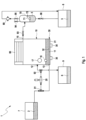
- Fig. 1 shows a block diagram of a distillation plant 1 according to an embodiment of the invention.
- the system 1 can be used to distill a liquid 5 from a dirty liquid 2. If, for example, metal parts were removed from greasy or oily dirt using the liquid 5, the resulting dirty liquid 2 contains the liquid 5 and the greasy or oily dirt contained in the liquid 5.
- the distillation plant 1 comprises a distillation tank 10, a fill level sensor 16 defining a target filling level of a dirty liquid 2 and arranged in the distillation tank 10 for detecting a defined filling level of the dirty liquid 2, an inlet pump 20 fluidly connected to the distillation tank 10 for introducing the dirty liquid 2 and one with the Distillation tank 10 thermally connected and arranged on an outside of the distillation tank 10 heating device 30.
- the distillation tank 10 also includes a dirty liquid connection 12 for introducing the dirty liquid 2 into the distillation tank, a liquid connection 15 for removing condensed liquid 5 from the distillation tank 10 and a residue connection 13 for draining a residue liquid 6 forming a distillation residue from the distillation tank 10, in which the dirt contained is enriched.
- the distillation system 1 includes a first 3-way valve 91 and a second 3-way valve 92, each of which is fluidly connected to the inlet pump 20.
- the first 3-way valve 91 is also fluidly connected to the residue connection 13.
- a dirty liquid container 7 providing the dirty liquid 2 is also connected to the first 3-way valve 91.
- the second 3-way valve 92 is also fluidly connected to the dirty liquid connection 12.
- a residue container 9 that receives the drained residue liquid is also connected to the second 3-way valve 92. Thanks to this relative arrangement of the 3-way valves 91, 92, the feed pump 20 and the distillation tank 10, the feed pump 20 can alternatively be used as a drain pump 20 for the residual liquid.
- the distillation plant 1 further comprises an intermediate container 70 for the condensed liquid 5, which is separably fluidly connected to the distillation container 10 by means of a connecting valve 93, a fill level sensor 71 assigned to the intermediate container 70, a working pressure sensor 72 assigned to the intermediate container 71 and an outlet closure arranged in a bottom of the intermediate container 70 for discharging the liquid 5.
- the distillation system 1 also includes a vacuum pump 80 which is separably fluidly connected to the intermediate container 70 by means of an evacuation valve 95.
- the distillation system 1 comprises a ventilation connection arranged on the intermediate container 70 with a ventilation valve 94 which is fluidically connected to the ventilation connection for ventilation of the intermediate container 70.
- a liquid container 8 for receiving recovered liquid 5 is separably fluidly connected to the outlet connection of the intermediate container 70 by means of a liquid outlet valve 96.
- the distillation system 1 comprises a condenser 60 and a heating device 30 which is thermally connected to the distillation container 10 and arranged on an outside of the distillation container 10.
- the heating device 30 has two channels 35 for water and a flat heating surface 32, which has a flat bottom 11 of the Distillation tank 10 is in the system.
- An outer surface of the floor 11 is rectangular.
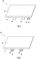
- Fig. 2 shows a schematic representation of a perspective view of the heating device 30 in FIG Fig. 1 Distillation system 1 shown.
- the heating device 30 comprises a steam container 31 for a water vapor, which has the flat heating surface 32.
- the heating surface 32 is rectangular.
- a contour of the heating surface 32 and a contour of the outer surface of the bottom 11 of the still 10 are identical.
- the heating device 30 further comprises a floor arranged opposite the heating surface 32, a filler neck 33 from the floor into the interior of the steam container 31 for filling the steam container 31 with water and one from the floor into the interior of the steam container 31 less far than the filler neck 33 protruding overflow nozzle 34 defining a target filling height of the water.
- the heating device 30 also includes two channels 35 formed on the floor.
- the overflow nozzle 34 can define a target filling height of 5 mm or a target filling height in a range from 2 mm to 10 mm. This ensures that the channels 35 are filled with water during operation of the heating device 30.
- Fig. 3 shows a schematic representation of another perspective view of the in Fig. 2 shown heating device 30.
- Each channel 35 has an opening 36 formed in a lateral end face of the channel 35, which can be penetrated and closed by a heating element.
- Fig. 4 shows a schematic representation of a partial side view of the in Fig. 1 shown distillation plant 1.
- the heating device 30 of the distillation plant 1 further comprises a pipe cross 42 and a filling pipe 40 which is fluidly connected to the filler neck 33 and which has a pipe turn 41 and fluidly connects the filler neck 33 and the pipe cross 42.
- the heating device 30 also includes a pressure relief valve 43, a steam pressure sensor 44 and a water connection 45, which are each connected to the pipe cross 42 and are fluidly connected to the filler neck 33.
- the pressure relief valve 43 is configured to open at a vapor pressure of at least 6 bar.
- the filling pipe 40 has a vent valve 46 between the filling neck 33 and the pipe turn 41.
- Fig. 5 shows a schematic representation of a cross-sectional view of the distillation vessel 10 in Fig. 1 shown distillation plant 1.
- the distillation tank 10 comprises a ceiling arranged opposite the floor 11 and a circumferential wall which extends from an edge of the floor 11 to an edge of the ceiling and connects the floor 11 and the ceiling all around.
- the dirty liquid connection 12, the residue connection 13 and the liquid connection 14 are each formed in the peripheral wall of the distillation vessel 10.
- the distillation tank 10 has a collecting channel 14 formed in the peripheral wall for collecting the condensed liquid 5, which is fluidly connected to the liquid connection 15.
- the condenser 60 may include a stainless steel header and a plurality of copper tubes fluidly connected to the stainless steel header and is arranged opposite the bottom 11 in the distillation vessel 10 with respect to the collecting trough 14.
- the dirty liquid 2 completely covers the bottom 11 of the distillation vessel.
- the target filling height defined by the filling level sensor 16 is 50 mm and can be in a range from 30 mm to 80 mm.
- a foam 3 can be arranged at a liquid level formed at the filling height as a result of the introduction of the dirty liquid 2 or the evaporation of the liquid 5 from the dirty liquid 2.
- a liquid vapor 4, ie an evaporated liquid 5, is arranged on the side of the liquid level, or the foam 3, facing away from the floor.
- the collecting trough 14 is designed at a distance from the foam 3 in a normal direction of the bottom 11 in such a way that the foam 3 does not get into the collecting trough 14, which prevents contamination of the condensed liquid 5 and ensures a high level of purity of the recovered liquid 5.
- Fig. 6 shows a schematic representation of a perspective side view of the in Fig. 1 shown distillation system 1.
- the distillation system 1 comprises the fill level sensor 71 arranged in a peripheral wall of the intermediate container 70, the working pressure sensor arranged in the peripheral wall of the intermediate container 70 and two electrically operated tubular heating elements 37, which pass through and close the openings 36 of the channels 35 of the heating device 30 as heating elements .
- a valve control device 90 is another component of the distillation system 1.
- the valve control device 90 is equipped with the first 3-way valve 91, the second 3-way valve 92, the connection valve 93, the ventilation valve 94, the evacuation valve 95 and the liquid outlet valve 96, respectively fluidly connected and configured, the valves 91, 92, 93, 94, 95, 96 to be operated pneumatically independently of each other, ie to be opened or closed individually.
- Fig. 7 shows a schematic representation of a front view of the in Fig. 1 shown distillation system 1.
- the distillation system 1 also includes a control device 50 with a human-machine interface such as a touch-sensitive screen, which is connected to the fill level sensor 16, the temperature sensor 17, the inlet pump 20, the two tubular heaters 37, the Capacitor 60, the level sensor 71, the working pressure sensor 72, the vacuum pump 80 and the valve control device 90 is electrically connected.
- a human-machine interface such as a touch-sensitive screen
- the control unit 50 is configured to stop the inlet pump 20 if the predetermined target filling level of the dirty liquid 2 is detected by the level sensor 16, and to start the inlet pump 20 if the predetermined target filling level is not detected by the level sensor 16.
- the control device 50 is further configured to open the liquid outlet valve 96 for a predetermined period of time when the predetermined maximum filling level of the liquid 5 in the intermediate container 70 is detected by the filling level sensor 71.
- the control unit 50 is configured to allow the dirty liquid to become a residual liquid during a post-distillation period and then to automatically drain the residual liquid if the filling level sensor 16 continues to detect the predetermined target filling level after a predetermined working period beginning with stopping the inlet pump 20.
- the steam container 31 of the heating device Before operating the distillation system 1, the steam container 31 of the heating device is filled by introducing water into the water connection 45 until the water flows out of the overflow connection 34. Then the water connection 45 and the overflow nozzle 34 are closed.
- the distillation plant 1 is controlled by the control unit 50.
- the dirty liquid 2 containing the liquid 5 is automatically arranged in the distillation tank 10 by a controlled introduction of the dirty liquid 2 into the distillation tank 10 of the distillation system 1.
- the control unit 50 sets the first 3-way valve 91 and the second 3-way valve 92 in such a way that the inlet pump 20 is fluidly connected to the dirty liquid container 7 and the dirty liquid connection 12 of the distillation tank 10, and starts the inlet pump 20.
- the control device 50 starts the feed pump 20.
- the dirty liquid 2 is introduced from the dirty liquid tank 7 into the distillation tank 10 by the feed pump 20.
- the control unit 50 stops the inlet pump 20.
- control device 50 actuates the two tubular heating elements 37 in order to generate steam with a maximum temperature of 160 ° C and with a maximum steam pressure of 6 bar in the steam tank 31 of the heating device 30.
- the dirty liquid 2 arranged in the distillation tank 10 is heated with the water vapor.
- the evaporated liquid 5 is liquefied by condensation in the distillation vessel 10 by the condenser 60 arranged in the distillation vessel 10.
- the condensed liquid 5 is collected.
- the condensed liquid 5 is removed from the distillation tank 10 and arranged in the intermediate container 70 of the distillation plant 1 that is fluidly connected to the distillation tank 10 and is different from the distillation tank 10.
- the collected liquid 5 is removed from the intermediate container 70 in a controlled manner. If the fill level sensor 71 of the intermediate container 70, which defines the predetermined maximum filling height of the liquid 5, detects that the defined predetermined maximum filling height is exceeded, the control device 50 opens the liquid outlet valve 96 for a predetermined period of time, which is 10 seconds (s) and can be between 5 s and 20 s . The collected liquid 5 is discharged from the intermediate container 70 into the liquid container 8 for the predetermined period of time.
- the control unit 50 sets the first 3-way valve 91 and the second 3-way valve 92 in such a way that the inlet pump 20 is fluidly connected to the residue container 9 and the residue connection 13 of the distillation container 10 and functions as a drain pump and starts the inlet pump 20.
- the vacuum pump 80 provides a pressure detected by the working pressure sensor 72 in the intermediate container 70 and therefore a working pressure in the distillation tank 10 which is lower than an air pressure outside the distillation system 1.
- the control device 50 closes the connection valve 93, opens the ventilation valve 94 of the intermediate container 70 and stops the vacuum pump 80.
- the control unit 50 closes the ventilation valve 94, starts the vacuum pump 80 and starts the vacuum pump.
- the control device 50 opens the connecting valve 93.
Landscapes
- Chemical & Material Sciences (AREA)
- Chemical Kinetics & Catalysis (AREA)
- Vaporization, Distillation, Condensation, Sublimation, And Cold Traps (AREA)
Priority Applications (2)
| Application Number | Priority Date | Filing Date | Title |
|---|---|---|---|
| RS20240088A RS65135B1 (sr) | 2019-12-05 | 2020-07-18 | Metod i postrojenje za destilaciju tečnosti |
| HRP20240137TT HRP20240137T1 (hr) | 2019-12-05 | 2020-07-18 | Postupak i uređaj za destilaciju tekućine |
Applications Claiming Priority (2)
| Application Number | Priority Date | Filing Date | Title |
|---|---|---|---|
| DE102019008444.6A DE102019008444A1 (de) | 2019-12-05 | 2019-12-05 | Verfahren und Anlage zum Destillieren einer Flüssigkeit |
| PCT/DE2020/000161 WO2021110187A1 (de) | 2019-12-05 | 2020-07-18 | Verfahren und anlage zum destillieren einer flüssigkeit |
Publications (3)
| Publication Number | Publication Date |
|---|---|
| EP4069394A1 EP4069394A1 (de) | 2022-10-12 |
| EP4069394B1 true EP4069394B1 (de) | 2023-11-29 |
| EP4069394C0 EP4069394C0 (de) | 2023-11-29 |
Family
ID=72147848
Family Applications (1)
| Application Number | Title | Priority Date | Filing Date |
|---|---|---|---|
| EP20758108.3A Active EP4069394B1 (de) | 2019-12-05 | 2020-07-18 | Verfahren und anlage zum destillieren einer flüssigkeit |
Country Status (11)
| Country | Link |
|---|---|
| EP (1) | EP4069394B1 (pl) |
| CN (1) | CN113396002A (pl) |
| BR (1) | BR112022010240A2 (pl) |
| DE (1) | DE102019008444A1 (pl) |
| ES (1) | ES2972310T3 (pl) |
| HR (1) | HRP20240137T1 (pl) |
| HU (1) | HUE065400T2 (pl) |
| MX (1) | MX2022006834A (pl) |
| PL (1) | PL4069394T3 (pl) |
| RS (1) | RS65135B1 (pl) |
| WO (1) | WO2021110187A1 (pl) |
Families Citing this family (1)
| Publication number | Priority date | Publication date | Assignee | Title |
|---|---|---|---|---|
| CN115500751A (zh) * | 2022-09-20 | 2022-12-23 | 深圳市杉川机器人有限公司 | 基站的控制方法和具有其的基站 |
Family Cites Families (17)
| Publication number | Priority date | Publication date | Assignee | Title |
|---|---|---|---|---|
| US3915808A (en) * | 1974-03-18 | 1975-10-28 | Riggs & Lombard Inc | Automatic distilling system |
| DE2934440A1 (de) * | 1979-08-25 | 1981-03-26 | Eisfink Carl Fink GmbH & Co, 71679 Asperg | Vorrichtung zur rueckgewinnung von mit polyurethanschaum vermischtem methylenchlorid |
| US4246116A (en) * | 1979-10-22 | 1981-01-20 | Cormack Robert G | Degreaser freeboard control |
| US4279704A (en) * | 1980-08-08 | 1981-07-21 | Noble Sr Kenneth E | Dry cleaning still apparatus |
| JPS58112401U (ja) * | 1982-01-20 | 1983-08-01 | 三洋電機株式会社 | 蒸溜装置 |
| US4534830A (en) * | 1983-04-22 | 1985-08-13 | Zerpa Industries, Inc. | Solvent recovery method |
| US4536256A (en) * | 1983-07-20 | 1985-08-20 | Recyclene Products, Inc. | Solvent recovery apparatus |
| DE19507126A1 (de) * | 1995-03-01 | 1996-09-12 | Esa Tech Dr Baumann Gmbh | Verfahren und Vorrichtung zur Wiederaufbereitung eines verunreinigten Lösemittels |
| IL136958A0 (en) * | 1997-12-25 | 2001-06-14 | Ebara Corp | Desalination method and desalination apparatus |
| CA2421141C (en) * | 2003-03-12 | 2015-02-10 | Vasil Iliev Mochev | Mobile distillery for water and steam distillation, based on the old traditions combined with a new method of distillation and new technical solutions of constructing system for production of etheral (essential) oils |
| JP2008055334A (ja) * | 2006-08-31 | 2008-03-13 | Sanyo Electric Co Ltd | 蒸留装置 |
| EP1985347A1 (de) * | 2007-04-27 | 2008-10-29 | Büchi Labortechnik AG | Verdampfer |
| CN201077924Y (zh) * | 2007-05-15 | 2008-06-25 | 上海雅森洗涤设备有限公司 | 石油碳氢干洗溶剂蒸馏回收装置 |
| DE102011121650A1 (de) * | 2011-12-19 | 2013-06-20 | Hans Heidolph Gmbh & Co. Kg | Destillationsvorrichtung |
| US10144688B2 (en) * | 2016-03-17 | 2018-12-04 | Aéro Mag 2000 Rrr Inc. | Method and system for recycling spent ethylene glycol from recovered aircraft de-icing solutions |
| CL2016002865A1 (es) * | 2016-11-10 | 2017-03-24 | Ramiro Senoret Verdugo | Dispositivo para extracción de aceites volátiles contenidos en la materia prima orgánica vía destilación por arrastre de vapor y método de destilación. |
| CN109875388A (zh) * | 2019-04-04 | 2019-06-14 | 佛山市新汇力金属科技有限公司 | 一种高效蒸汽加热方法及实现该方法的设备 |
-
2019
- 2019-12-05 DE DE102019008444.6A patent/DE102019008444A1/de not_active Withdrawn
-
2020
- 2020-07-18 RS RS20240088A patent/RS65135B1/sr unknown
- 2020-07-18 CN CN202080012469.0A patent/CN113396002A/zh active Pending
- 2020-07-18 HR HRP20240137TT patent/HRP20240137T1/hr unknown
- 2020-07-18 ES ES20758108T patent/ES2972310T3/es active Active
- 2020-07-18 EP EP20758108.3A patent/EP4069394B1/de active Active
- 2020-07-18 PL PL20758108.3T patent/PL4069394T3/pl unknown
- 2020-07-18 BR BR112022010240A patent/BR112022010240A2/pt unknown
- 2020-07-18 WO PCT/DE2020/000161 patent/WO2021110187A1/de not_active Ceased
- 2020-07-18 HU HUE20758108A patent/HUE065400T2/hu unknown
- 2020-07-18 MX MX2022006834A patent/MX2022006834A/es unknown
Also Published As
| Publication number | Publication date |
|---|---|
| BR112022010240A2 (pt) | 2022-09-06 |
| PL4069394T3 (pl) | 2024-04-22 |
| RS65135B1 (sr) | 2024-02-29 |
| WO2021110187A1 (de) | 2021-06-10 |
| DE102019008444A1 (de) | 2021-06-24 |
| EP4069394C0 (de) | 2023-11-29 |
| ES2972310T3 (es) | 2024-06-12 |
| HRP20240137T1 (hr) | 2024-04-12 |
| EP4069394A1 (de) | 2022-10-12 |
| HUE065400T2 (hu) | 2024-05-28 |
| MX2022006834A (es) | 2022-09-19 |
| CN113396002A (zh) | 2021-09-14 |
Similar Documents
| Publication | Publication Date | Title |
|---|---|---|
| EP2832241B1 (de) | Vorrichtung und verfahren zur kondensation eines dampfes in einer vakuumkammer | |
| DE102011121650A1 (de) | Destillationsvorrichtung | |
| DE19639022B4 (de) | Verfahren und Vorrichtung zum Herstellen hochreiner flüssiger Chemikalien | |
| EP4069394B1 (de) | Verfahren und anlage zum destillieren einer flüssigkeit | |
| WO2010034043A1 (de) | Plattenfallfilm-kurzweg verdampfer | |
| DE19637313C2 (de) | Vorrichtung zum Aufheizen von Teilen | |
| DE112011101458B4 (de) | Trinkwasserspender mit Destillationsvorrichtung | |
| EP4237114A1 (de) | Prozesswasserdestillationsanlage und verfahren zum betreiben einer prozesswasserdestillationsanlage | |
| DE3513021A1 (de) | Verfahren und vorrichtung zum waermebehandeln von fliessfaehigen materialien | |
| DE10251570A1 (de) | Feststoffseparator | |
| DE1767207A1 (de) | Destillationsanlage | |
| DE60013484T2 (de) | Verfahren zur reinigung von objekten durch eine erwärmte flüssigkeit und anlage zur durchführung dieses verfahrens | |
| EP3165859A1 (de) | Vakuumkühlvorrichtung und verfahren zur vakuumkühlung von lebensmitteln | |
| DE3014831C2 (pl) | ||
| EP3029403B1 (de) | Verfahren und Vorrichtung zum Trocknen der Feststoffisolation des Aktivteils eines elektrischen Gerätes nach der Vapour-Phase Methode | |
| EP1671709B1 (de) | Verfahren und Vorrichtung zum Erzeugen von Heissdampf für Reinigungs- oder Dekontaminationszwecke | |
| DE19639160C2 (de) | Trockenvorrichtung mit Dampfaufbereitung | |
| DE535841C (de) | Verfahren und Vorrichtung zum Extrahieren von OElen und Harzen des Hopfens | |
| DE102015219259B4 (de) | Gaskondensationsvorrichtung mit Rückstromseparator | |
| DE2713266A1 (de) | Fluessigkeitsbehandlungssystem mit dampfkompression | |
| DE4128699A1 (de) | Verfahren und vorrichtung zum entfetten und reinigen von behandlungsgut mit hilfe von loesungsmitteln | |
| DE4421061C2 (de) | Verfahren zum Oberflächenbehandeln industrieller Teile in einer Behandlungsanlage sowie Anlage zur Durchführung des Verfahrens | |
| DE2420040A1 (de) | Anordnung zum destillieren | |
| EP2996823A1 (de) | Anlage zur reinigung von bauteilen | |
| DE1115222B (de) | Verfahren und Vorrichtung zum Abtrennen von festen Verunreinigungen und/oder emulgiertem Wasser aus organischen Loesungsmitteln und OElen |
Legal Events
| Date | Code | Title | Description |
|---|---|---|---|
| STAA | Information on the status of an ep patent application or granted ep patent |
Free format text: STATUS: UNKNOWN |
|
| STAA | Information on the status of an ep patent application or granted ep patent |
Free format text: STATUS: THE INTERNATIONAL PUBLICATION HAS BEEN MADE |
|
| PUAI | Public reference made under article 153(3) epc to a published international application that has entered the european phase |
Free format text: ORIGINAL CODE: 0009012 |
|
| STAA | Information on the status of an ep patent application or granted ep patent |
Free format text: STATUS: REQUEST FOR EXAMINATION WAS MADE |
|
| 17P | Request for examination filed |
Effective date: 20220701 |
|
| AK | Designated contracting states |
Kind code of ref document: A1 Designated state(s): AL AT BE BG CH CY CZ DE DK EE ES FI FR GB GR HR HU IE IS IT LI LT LU LV MC MK MT NL NO PL PT RO RS SE SI SK SM TR |
|
| DAV | Request for validation of the european patent (deleted) | ||
| DAX | Request for extension of the european patent (deleted) | ||
| GRAP | Despatch of communication of intention to grant a patent |
Free format text: ORIGINAL CODE: EPIDOSNIGR1 |
|
| STAA | Information on the status of an ep patent application or granted ep patent |
Free format text: STATUS: GRANT OF PATENT IS INTENDED |
|
| INTG | Intention to grant announced |
Effective date: 20230530 |
|
| GRAS | Grant fee paid |
Free format text: ORIGINAL CODE: EPIDOSNIGR3 |
|
| GRAA | (expected) grant |
Free format text: ORIGINAL CODE: 0009210 |
|
| STAA | Information on the status of an ep patent application or granted ep patent |
Free format text: STATUS: THE PATENT HAS BEEN GRANTED |
|
| AK | Designated contracting states |
Kind code of ref document: B1 Designated state(s): AL AT BE BG CH CY CZ DE DK EE ES FI FR GB GR HR HU IE IS IT LI LT LU LV MC MK MT NL NO PL PT RO RS SE SI SK SM TR |
|
| REG | Reference to a national code |
Ref country code: GB Ref legal event code: FG4D Free format text: NOT ENGLISH |
|
| REG | Reference to a national code |
Ref country code: CH Ref legal event code: EP |
|
| REG | Reference to a national code |
Ref country code: DE Ref legal event code: R096 Ref document number: 502020006212 Country of ref document: DE |
|
| REG | Reference to a national code |
Ref country code: IE Ref legal event code: FG4D Free format text: LANGUAGE OF EP DOCUMENT: GERMAN |
|
| U01 | Request for unitary effect filed |
Effective date: 20231221 |
|
| U07 | Unitary effect registered |
Designated state(s): AT BE BG DE DK EE FI FR IT LT LU LV MT NL PT SE SI Effective date: 20240105 |
|
| PG25 | Lapsed in a contracting state [announced via postgrant information from national office to epo] |
Ref country code: GR Free format text: LAPSE BECAUSE OF FAILURE TO SUBMIT A TRANSLATION OF THE DESCRIPTION OR TO PAY THE FEE WITHIN THE PRESCRIBED TIME-LIMIT Effective date: 20240301 |
|
| PG25 | Lapsed in a contracting state [announced via postgrant information from national office to epo] |
Ref country code: IS Free format text: LAPSE BECAUSE OF FAILURE TO SUBMIT A TRANSLATION OF THE DESCRIPTION OR TO PAY THE FEE WITHIN THE PRESCRIBED TIME-LIMIT Effective date: 20240329 |
|
| REG | Reference to a national code |
Ref country code: SK Ref legal event code: T3 Ref document number: E 43522 Country of ref document: SK |
|
| REG | Reference to a national code |
Ref country code: HR Ref legal event code: T1PR Ref document number: P20240137 Country of ref document: HR |
|
| PG25 | Lapsed in a contracting state [announced via postgrant information from national office to epo] |
Ref country code: IS Free format text: LAPSE BECAUSE OF FAILURE TO SUBMIT A TRANSLATION OF THE DESCRIPTION OR TO PAY THE FEE WITHIN THE PRESCRIBED TIME-LIMIT Effective date: 20240329 Ref country code: GR Free format text: LAPSE BECAUSE OF FAILURE TO SUBMIT A TRANSLATION OF THE DESCRIPTION OR TO PAY THE FEE WITHIN THE PRESCRIBED TIME-LIMIT Effective date: 20240301 |
|
| REG | Reference to a national code |
Ref country code: HU Ref legal event code: AG4A Ref document number: E065400 Country of ref document: HU |
|
| REG | Reference to a national code |
Ref country code: ES Ref legal event code: FG2A Ref document number: 2972310 Country of ref document: ES Kind code of ref document: T3 Effective date: 20240612 |
|
| REG | Reference to a national code |
Ref country code: HR Ref legal event code: ODRP Ref document number: P20240137 Country of ref document: HR Payment date: 20240627 Year of fee payment: 5 |
|
| PG25 | Lapsed in a contracting state [announced via postgrant information from national office to epo] |
Ref country code: SM Free format text: LAPSE BECAUSE OF FAILURE TO SUBMIT A TRANSLATION OF THE DESCRIPTION OR TO PAY THE FEE WITHIN THE PRESCRIBED TIME-LIMIT Effective date: 20231129 Ref country code: RO Free format text: LAPSE BECAUSE OF FAILURE TO SUBMIT A TRANSLATION OF THE DESCRIPTION OR TO PAY THE FEE WITHIN THE PRESCRIBED TIME-LIMIT Effective date: 20231129 |
|
| U20 | Renewal fee for the european patent with unitary effect paid |
Year of fee payment: 5 Effective date: 20240619 |
|
| REG | Reference to a national code |
Ref country code: DE Ref legal event code: R097 Ref document number: 502020006212 Country of ref document: DE |
|
| PLBE | No opposition filed within time limit |
Free format text: ORIGINAL CODE: 0009261 |
|
| STAA | Information on the status of an ep patent application or granted ep patent |
Free format text: STATUS: NO OPPOSITION FILED WITHIN TIME LIMIT |
|
| 26N | No opposition filed |
Effective date: 20240830 |
|
| PG25 | Lapsed in a contracting state [announced via postgrant information from national office to epo] |
Ref country code: MC Free format text: LAPSE BECAUSE OF FAILURE TO SUBMIT A TRANSLATION OF THE DESCRIPTION OR TO PAY THE FEE WITHIN THE PRESCRIBED TIME-LIMIT Effective date: 20231129 |
|
| U20 | Renewal fee for the european patent with unitary effect paid |
Year of fee payment: 6 Effective date: 20250507 |
|
| PGFP | Annual fee paid to national office [announced via postgrant information from national office to epo] |
Ref country code: PL Payment date: 20250514 Year of fee payment: 6 |
|
| PGFP | Annual fee paid to national office [announced via postgrant information from national office to epo] |
Ref country code: GB Payment date: 20250618 Year of fee payment: 6 |
|
| PGFP | Annual fee paid to national office [announced via postgrant information from national office to epo] |
Ref country code: RS Payment date: 20250602 Year of fee payment: 6 |
|
| PGFP | Annual fee paid to national office [announced via postgrant information from national office to epo] |
Ref country code: HR Payment date: 20250602 Year of fee payment: 6 |
|
| PGFP | Annual fee paid to national office [announced via postgrant information from national office to epo] |
Ref country code: TR Payment date: 20250603 Year of fee payment: 6 Ref country code: SK Payment date: 20250604 Year of fee payment: 6 |
|
| PGFP | Annual fee paid to national office [announced via postgrant information from national office to epo] |
Ref country code: CZ Payment date: 20250604 Year of fee payment: 6 |
|
| PG25 | Lapsed in a contracting state [announced via postgrant information from national office to epo] |
Ref country code: IE Free format text: LAPSE BECAUSE OF NON-PAYMENT OF DUE FEES Effective date: 20240718 |
|
| REG | Reference to a national code |
Ref country code: HR Ref legal event code: ODRP Ref document number: P20240137 Country of ref document: HR Payment date: 20250602 Year of fee payment: 6 |
|
| PGFP | Annual fee paid to national office [announced via postgrant information from national office to epo] |
Ref country code: HU Payment date: 20250606 Year of fee payment: 6 |
|
| PGFP | Annual fee paid to national office [announced via postgrant information from national office to epo] |
Ref country code: ES Payment date: 20250804 Year of fee payment: 6 |
|
| PGFP | Annual fee paid to national office [announced via postgrant information from national office to epo] |
Ref country code: NO Payment date: 20250722 Year of fee payment: 6 |
|
| PGFP | Annual fee paid to national office [announced via postgrant information from national office to epo] |
Ref country code: CH Payment date: 20250801 Year of fee payment: 6 |
|
| PG25 | Lapsed in a contracting state [announced via postgrant information from national office to epo] |
Ref country code: CY Free format text: LAPSE BECAUSE OF FAILURE TO SUBMIT A TRANSLATION OF THE DESCRIPTION OR TO PAY THE FEE WITHIN THE PRESCRIBED TIME-LIMIT; INVALID AB INITIO Effective date: 20200718 |