EP4068435A1 - Membranelektrode; deren herstellungsverfahren und brennstoffzelle - Google Patents
Membranelektrode; deren herstellungsverfahren und brennstoffzelle Download PDFInfo
- Publication number
- EP4068435A1 EP4068435A1 EP19954609.4A EP19954609A EP4068435A1 EP 4068435 A1 EP4068435 A1 EP 4068435A1 EP 19954609 A EP19954609 A EP 19954609A EP 4068435 A1 EP4068435 A1 EP 4068435A1
- Authority
- EP
- European Patent Office
- Prior art keywords
- catalyst
- anode
- membrane electrode
- hydrogen oxidation
- electrode assembly
- Prior art date
- Legal status (The legal status is an assumption and is not a legal conclusion. Google has not performed a legal analysis and makes no representation as to the accuracy of the status listed.)
- Pending
Links
Images


Classifications
-
- H—ELECTRICITY
- H01—ELECTRIC ELEMENTS
- H01M—PROCESSES OR MEANS, e.g. BATTERIES, FOR THE DIRECT CONVERSION OF CHEMICAL ENERGY INTO ELECTRICAL ENERGY
- H01M8/00—Fuel cells; Manufacture thereof
- H01M8/10—Fuel cells with solid electrolytes
- H01M8/1004—Fuel cells with solid electrolytes characterised by membrane-electrode assemblies [MEA]
-
- H—ELECTRICITY
- H01—ELECTRIC ELEMENTS
- H01M—PROCESSES OR MEANS, e.g. BATTERIES, FOR THE DIRECT CONVERSION OF CHEMICAL ENERGY INTO ELECTRICAL ENERGY
- H01M4/00—Electrodes
- H01M4/86—Inert electrodes with catalytic activity, e.g. for fuel cells
- H01M4/8647—Inert electrodes with catalytic activity, e.g. for fuel cells consisting of more than one material, e.g. consisting of composites
- H01M4/8657—Inert electrodes with catalytic activity, e.g. for fuel cells consisting of more than one material, e.g. consisting of composites layered
-
- H—ELECTRICITY
- H01—ELECTRIC ELEMENTS
- H01M—PROCESSES OR MEANS, e.g. BATTERIES, FOR THE DIRECT CONVERSION OF CHEMICAL ENERGY INTO ELECTRICAL ENERGY
- H01M4/00—Electrodes
- H01M4/86—Inert electrodes with catalytic activity, e.g. for fuel cells
- H01M4/88—Processes of manufacture
- H01M4/8803—Supports for the deposition of the catalytic active composition
- H01M4/881—Electrolytic membranes
-
- H—ELECTRICITY
- H01—ELECTRIC ELEMENTS
- H01M—PROCESSES OR MEANS, e.g. BATTERIES, FOR THE DIRECT CONVERSION OF CHEMICAL ENERGY INTO ELECTRICAL ENERGY
- H01M4/00—Electrodes
- H01M4/86—Inert electrodes with catalytic activity, e.g. for fuel cells
- H01M4/88—Processes of manufacture
- H01M4/8825—Methods for deposition of the catalytic active composition
- H01M4/8828—Coating with slurry or ink
-
- H—ELECTRICITY
- H01—ELECTRIC ELEMENTS
- H01M—PROCESSES OR MEANS, e.g. BATTERIES, FOR THE DIRECT CONVERSION OF CHEMICAL ENERGY INTO ELECTRICAL ENERGY
- H01M4/00—Electrodes
- H01M4/86—Inert electrodes with catalytic activity, e.g. for fuel cells
- H01M4/90—Selection of catalytic material
- H01M4/92—Metals of platinum group
- H01M4/921—Alloys or mixtures with metallic elements
-
- H—ELECTRICITY
- H01—ELECTRIC ELEMENTS
- H01M—PROCESSES OR MEANS, e.g. BATTERIES, FOR THE DIRECT CONVERSION OF CHEMICAL ENERGY INTO ELECTRICAL ENERGY
- H01M4/00—Electrodes
- H01M4/86—Inert electrodes with catalytic activity, e.g. for fuel cells
- H01M4/90—Selection of catalytic material
- H01M4/92—Metals of platinum group
- H01M4/923—Compounds thereof with non-metallic elements
-
- H—ELECTRICITY
- H01—ELECTRIC ELEMENTS
- H01M—PROCESSES OR MEANS, e.g. BATTERIES, FOR THE DIRECT CONVERSION OF CHEMICAL ENERGY INTO ELECTRICAL ENERGY
- H01M4/00—Electrodes
- H01M4/86—Inert electrodes with catalytic activity, e.g. for fuel cells
- H01M4/90—Selection of catalytic material
- H01M4/92—Metals of platinum group
- H01M4/925—Metals of platinum group supported on carriers, e.g. powder carriers
- H01M4/926—Metals of platinum group supported on carriers, e.g. powder carriers on carbon or graphite
-
- H—ELECTRICITY
- H01—ELECTRIC ELEMENTS
- H01M—PROCESSES OR MEANS, e.g. BATTERIES, FOR THE DIRECT CONVERSION OF CHEMICAL ENERGY INTO ELECTRICAL ENERGY
- H01M8/00—Fuel cells; Manufacture thereof
- H01M8/10—Fuel cells with solid electrolytes
- H01M2008/1095—Fuel cells with polymeric electrolytes
-
- H—ELECTRICITY
- H01—ELECTRIC ELEMENTS
- H01M—PROCESSES OR MEANS, e.g. BATTERIES, FOR THE DIRECT CONVERSION OF CHEMICAL ENERGY INTO ELECTRICAL ENERGY
- H01M4/00—Electrodes
- H01M4/86—Inert electrodes with catalytic activity, e.g. for fuel cells
- H01M4/88—Processes of manufacture
- H01M4/8803—Supports for the deposition of the catalytic active composition
- H01M4/8807—Gas diffusion layers
-
- H—ELECTRICITY
- H01—ELECTRIC ELEMENTS
- H01M—PROCESSES OR MEANS, e.g. BATTERIES, FOR THE DIRECT CONVERSION OF CHEMICAL ENERGY INTO ELECTRICAL ENERGY
- H01M4/00—Electrodes
- H01M4/86—Inert electrodes with catalytic activity, e.g. for fuel cells
- H01M4/88—Processes of manufacture
- H01M4/8825—Methods for deposition of the catalytic active composition
- H01M4/886—Powder spraying, e.g. wet or dry powder spraying, plasma spraying
-
- Y—GENERAL TAGGING OF NEW TECHNOLOGICAL DEVELOPMENTS; GENERAL TAGGING OF CROSS-SECTIONAL TECHNOLOGIES SPANNING OVER SEVERAL SECTIONS OF THE IPC; TECHNICAL SUBJECTS COVERED BY FORMER USPC CROSS-REFERENCE ART COLLECTIONS [XRACs] AND DIGESTS
- Y02—TECHNOLOGIES OR APPLICATIONS FOR MITIGATION OR ADAPTATION AGAINST CLIMATE CHANGE
- Y02E—REDUCTION OF GREENHOUSE GAS [GHG] EMISSIONS, RELATED TO ENERGY GENERATION, TRANSMISSION OR DISTRIBUTION
- Y02E60/00—Enabling technologies; Technologies with a potential or indirect contribution to GHG emissions mitigation
- Y02E60/30—Hydrogen technology
- Y02E60/50—Fuel cells
Definitions
- the present disclosure relates to the technical field of full cell, in particular to a membrane electrode (membrane electrode assembly) and manufacturing method thereof, and a fuel cell.
- Proton exchange membrane fuel cell is a device that converts hydrogen energy into electric energy, and final emission thereof is only water, and the PEMFC is a clean, green and pollution-free power generation device, which has broad application prospects in the fields of automobile, ship, rail transit, fixed base station, and unmanned aerial vehicle and the like.
- the core components inside the proton exchange membrane fuel cell are called membrane electrode assemblies (MEA), which are the smallest primary unit for power generation.
- MEA membrane electrode assemblies
- the membrane electrode assembly may be damaged, which eventually lead to the failure of the fuel cell.
- lifespan thereof should be guaranteed, and the performance loss of the membrane electrode assembly under severe working conditions should be reduced and avoided.
- Cell reversal is one of the severe working conditions encountered during the operation of membrane electrode assemblies. Specifically, during the operation of the cell stack, when the anode of a single or multiple membrane electrode assemblies occurs water plugging or has ice condensed, the hydrogen transmission of the anode is hindered and the hydrogen cannot reach the surface of catalyst Pt to generate protons.
- the potential of the anode rises from 0V before cell reversal (relative to the standard hydrogen electrode, SHE) to higher than 1.5V in a short time, and at this time, the voltage of the membrane electrode assembly is usually lower than -1V; under the high potential of the anode, the carbon component reacts with water, and the carbon is corroded to generate a proton to sustain the current. The carbon continues to be corroded, eventually leading to the failure of the membrane electrode assembly.
- the prevention of the cell reversal of the fuel cell is mainly implemented through the voltage monitoring sensor.
- the principle of voltage monitoring is to detect the potential of the membrane electrode assembly, if the voltage of membrane electrode assembly changes from positive to negative, it means that the cell reversal occurs, and the circuit needs to be cut off in time. But when a situation that the voltage is changed to be negative is detected, the cell reversal has already occurred for a period of time, and the performance loss is still unavoidable.
- the existing membrane electrode assembly cannot well reduce the performance loss after cell reversal is occurred, and the membrane electrode assembly has a weak capability of resisting cell reversal.
- the purpose of the present disclosure is to provide a membrane electrode assembly, and manufacturing method thereof, and a fuel cell, which can effectively reduce the performance loss after cell reversal is occurred, extend the cell reversal tolerance time, and enhance the capability of resisting cell reversal for the membrane electrode assembly.
- the embodiments of the present disclosure provide a membrane electrode assembly, which comprises a proton exchange membrane, an anode catalyst, and an anode diffusion layer.
- the anode catalyst comprises a first catalyst layer and a second catalyst layer.
- the proton exchange membrane, the first catalyst layer, the second catalyst layer and the anode diffusion layer are arranged in sequence.
- the first catalyst layer includes a hydrogen oxidation catalyst
- the second catalyst layer includes a mixture of the hydrogen oxidation catalyst and a water electrolysis catalyst.
- the water electrolysis catalyst is provided on one side of the anode catalyst layer close to the anode diffusion layer, when the cell reversal occurs, carbon corrosion occurred at the water electrolysis catalyst can be reduced, and the water electrolysis catalyst can electrolyze the water on one side close to the anode diffusion layer, which can provide proton flow for the proton exchange membrane, reduce the carbon corrosion at the hydrogen oxidation catalyst, and extend the cell reversal tolerance time.
- Both the side close to the proton exchange membrane and the side close to the anode diffusion layer of the anode catalyst layer have the hydrogen oxidation catalyst, under the condition that there is enough hydrogen oxidation catalyst to provide the proton flow, since part of the hydrogen oxidation catalyst is formed on the side of the anode catalyst layer close to the anode diffusion layer, the carbon corrosion of the hydrogen oxidation catalyst can be further reduced, the performance loss after cell reversal occurs can be reduced, and the cell reversal tolerance time can be extended.
- FIG. 1 is a sectional view of a membrane electrode assembly 30 provided by an embodiment of the present disclosure.
- the membrane electrode assembly 30 includes a cathode diffusion layer 310, a cathode catalyst layer 320, a proton exchange membrane 330, an anode catalyst layer 340 and an anode diffusion layer 350 arranged in sequence.
- the anode catalyst layer 340 includes a first catalyst layer 341 and a second catalyst layer 342, the cathode diffusion layer 310, the cathode catalyst layer 320, the proton exchange membrane 330, the first catalyst layer 341, the second catalyst layer 342 and the anode diffusion layer 350 are arranged in sequence.
- the first catalyst layer 341 includes a hydrogen oxidation catalyst
- the second catalyst layer 342 includes a mixture of the hydrogen oxidation catalyst and a water electrolysis catalyst.
- both the side close to the proton exchange membrane 330 and the side close to the anode diffusion layer 350 of the anode catalyst layer 340 have the hydrogen oxidation catalyst, under the condition that there is enough hydrogen oxidation catalyst to provide the proton flow, since part of the hydrogen oxidation catalyst is formed on the side of the anode catalyst layer 340 close to the anode diffusion layer 350, the water content near the part of the hydrogen oxidation catalyst can be reduced, the carbon corrosion of the hydrogen oxidation catalyst can be reduced, the performance loss during cell reversal can be reduced.
- the water electrolysis catalyst is provided on one side of the anode catalyst layer 340 close to the anode diffusion layer 350, when the cell reversal occurs, carbon corrosion occurred at the water electrolysis catalyst can be reduced, and the water electrolysis catalyst can electrolyze the water on one side close to the anode diffusion layer 350, which can provide proton flow for the proton exchange membrane, reduce the carbon corrosion at the hydrogen oxidation catalyst, and extend the cell reversal tolerance time.
- the water electrolysis catalyst comprises a first carrier and an active component of the water electrolysis catalyst loaded on the first carrier.
- the hydrogen oxidation catalyst comprises a second carrier and an active component of the hydrogen oxidation catalyst loaded on the second carrier.
- the active components can be loaded on the corrosion-resistant carrier, the stronger the corrosion resistance of the anode carrier is, the slower the carbon corrosion is; and the less the carbon carrier is, the lower the performance loss during cell reversal is.
- the anode carrier (that is the first carrier and the second carrier) may be a conductive metal oxide or graphitic carbon. Both the graphitic carbon and the conductive metal oxide are the carrier resisting high potential (above 1.5V) corrosion, using the conductive metal oxide or the graphitic carbon as the anode carrier of active material can extend the cell reversal tolerance time.
- the conductive metal oxide does not contain carbon, which can avoid carbon corrosion.
- the conductive metal oxide is one selected from Ti 4 O 7 , Nb-TiO 2 and ITO.
- the graphitic carbon can be a graphitized carbon material, and after the carbon is graphitized, carbon corrosion can be reduced.
- the active component of the water electrolysis catalyst may be one or more of RuO 2 , IrO 2 , and RuxIr 1-x O 2 .
- the active component of the water electrolysis catalyst may be RuO 2 ; the active component of the water electrolysis catalyst may be IrO 2 ; the active component of the water electrolysis catalyst may be Ru x Ir 1-x O 2 ; the active component of the water electrolysis catalyst may be a mixture of RuO 2 and IrO 2 ; the active component of the water electrolysis catalyst may be a mixture of RuO 2 and Ru x Ir 1-x O 2 ; the active component of the water electrolysis catalyst may be a mixture of IrO 2 and Ru x Ir 1-x O 2 ; and the active component of the water electrolysis catalyst may be a mixture of RuO 2 , IrO 2 and Ru x Ir 1-x O 2 ; and the active component of the water electrolysis catalyst may be a mixture of RuO 2 , IrO 2 and Ru x Ir 1-x O 2 .
- the water electrolysis catalyst may provide proton flow through water electrolysis, and can reduce the potential of water electrolysis, which makes the anode potential relatively low, reduces carbon corrosion, and reduces the performance loss after cell reversal while ensuring the cell reversal tolerance time.
- the mass percentage of the active component of the water electrolysis catalyst in the water electrolysis catalyst is 10%-80%.
- the mass percentage of active component in the water electrolysis catalyst is 40%-80%.
- the active component of the hydrogen oxidation catalyst is a metal catalyst, which comprises one or more of Pt, Ir, Ptlr alloy and Pd.
- the active component of the hydrogen oxidation catalyst may be Pt; the active component of the hydrogen oxidation catalyst may be Ir; the active component of the hydrogen oxidation catalyst may be Ptlr alloy; and the active component of the hydrogen oxidation catalyst may be Pd.
- the active components of the hydrogen oxidation catalyst are not limited, as long as they can be used as the active components of the hydrogen oxidation catalyst, they are all within the protection scope of the present disclosure.
- the mass percentage of the active component of the hydrogen oxidation catalyst in the hydrogen oxidation catalyst is 10%-80%.
- the mass percentage of Pt in the hydrogen oxidation catalyst is 40%-80%.
- the hydrogen oxidation catalyst in the first catalyst layer 341 and the hydrogen oxidation catalyst in the second catalyst layer 342 may be of the same type or different.
- the active component of the hydrogen oxidation catalyst in the first catalyst layer 341 is Pt
- the active component of the hydrogen oxidation catalyst in the second catalyst layer 342 is also Pt
- the active component of the hydrogen oxidation catalyst in the first catalyst layer 341 is Pt
- the active component of the hydrogen oxidation catalyst in the second catalyst layer 342 is Ir
- the active component of the hydrogen oxidation catalyst in the first catalyst layer 341 is Ir
- the active component of the hydrogen oxidation catalyst in the second catalyst layer 342 is Pt.
- the mass ratio of the hydrogen oxidation catalyst in the first catalyst layer 341 and the hydrogen oxidation catalyst in the second catalyst layer 342 may be 1:10-1:0.1. Further, the mass ratio of the hydrogen oxidation catalyst in the first catalyst layer 341 and the hydrogen oxidation catalyst in the second catalyst layer 342 may be 1:5-1:0.5. Further, the mass ratio of the hydrogen oxidation catalyst in the first catalyst layer 341 and the hydrogen oxidation catalyst in the second catalyst layer 342 may be 1:2-1:0.8. Further, the mass ratio of the hydrogen oxidation catalyst in the first catalyst layer 341 and the hydrogen oxidation catalyst in the second catalyst layer 342 may be 1:1.
- the preparation method of the obtained membrane electrode assembly 30 may be as follows: forming the hydrogen oxidation catalyst on the anode side of the proton exchange membrane 330 to obtain the first catalyst layer 341, forming a mixture of hydrogen oxidation catalyst and the water electrolysis catalyst on the anode diffusion layer 350 to obtain the second catalyst layer 342, and attaching the first catalyst layer 341 and the second catalyst layer 342, or forming the hydrogen oxidation catalyst on the anode side of the proton exchange membrane 330 to obtain the first catalyst layer 341, and forming a mixture of the hydrogen oxidation catalyst and the water electrolysis catalyst on one side of the first catalyst layer 341 facing away from the proton exchange membrane 330 to obtain the second catalyst layer 342, and forming the anode diffusion layer 350 on one side of the second catalyst layer 342 facing away from the first catalyst layer 341.
- the above-mentioned membrane electrode assembly 30 may be obtained.
- the slurry of hydrogen oxidation catalyst is sprayed on the anode side of the proton exchange membrane 330 to obtain the first catalyst layer 341
- a mixed slurry of the water electrolysis catalyst and the hydrogen oxidation catalyst is sprayed on the anode diffusion layer 350 to obtain the second catalyst layer 342
- the first catalyst layer 341 and the second catalyst layer 342 are attached to each other.
- the membrane electrode assembly 30 obtained by the above-mentioned method can not only extend the cell reversal tolerance time of the membrane electrode assembly, but also reduce the performance loss during cell reversal of the membrane electrode assembly.
- the above-mentioned membrane electrode assembly is used to prepare a fuel cell, and thus the performance of the fuel cell is better.
- the cathode catalyst was 60% Pt/C (Ketjen Black)
- the anode HOR catalyst hydrogen oxidation catalyst
- Pt/GrC graphitized Ketjen Black
- IrO 2 /GrC graphitized Ketjen Black, the same as above, which will not be repeated hereafter).
- the cathode catalyst was 60% Pt/C
- the anode HOR catalyst was 40% Pt/GrC, which had the layered structure design
- the anode OER catalyst was 40% IrO 2 /GrC.
- the loading amount of Pt in the cathode catalyst was 0.4 mg Pt /cm 2 , which was sprayed on the cathode side of CCM (proton exchange membrane).
- the total loading amount of Pt in the anode HOR catalyst was 0.1 mg Pt /cm 2
- the loading amount of IrO 2 in the OER catalyst was 0.05 mg Ir /cm 2 .
- the cell reversal resistance test is the same as that of Comparative Example 1. After the cell reversal finished, the membrane electrode assembly was placed for 10 h to perform overnight recovery, and the V-I curve after cell reversal was tested to compare the performance loss.
- the cathode catalyst was 60% Pt/C
- the anode HOR catalyst was 70% Pt/GrC
- the anode OER catalyst was 70% IrO 2 /GrC.
- the cathode catalyst was 60%Pt/C
- the anode HOR catalyst was 70% Pt/GrC, which had the layered structure design
- the anode OER catalyst was 70% IrO 2 /GrC.
- the loading amount of Pt in the cathode catalyst was 0.4 mg Pt /cm 2 , which was sprayed on the cathode side of the CCM.
- the total loading amount of Pt in the anode HOR catalyst was 0.1 mg Pt /cm 2
- the loading amount of IrO 2 in the OER catalyst was 0.05 mg Ir /cm 2 .
- the cell reversal resistance test is the same as that of Comparative Example 1, after the cell reversal finished, the membrane electrode assembly was placed for 10 h to perform overnight recovery, and the V-I curve after cell reversal was tested to compare the performance loss.
- the cathode catalyst was 60% Pt/C
- the anode HOR catalyst was 40% Pt/GrC
- the anode OER catalyst was 40% IrO 2 /GrC.
- the cathode catalyst was 60% Pt/C
- the anode HOR catalyst was 40% Pt/GrC
- the anode OER catalyst was 40% IrO 2 /GrC.
- the loading amount of Pt in the cathode catalyst was 0.4 mg Pt /cm 2 , which was sprayed on the cathode side of the CCM.
- the loading amount of Pt in the anode HOR catalyst was 0.1 mg Pt /cm 2 , which was sprayed on the anode side of the CCM
- the loading amount of IrO 2 in the OER catalyst was 0.1 mg Ir /cm 2 , which was sprayed on the anode diffusion layer (GDL).
- the condition for the cell reversal resistance test was: anode flow rate: 1slpm, cathode flow rate: 1slpm, test temperature: 75°C, relative humidity: anode 100%RH, cathode 100%RH, and test pressure: normal pressure.
- the cathode catalyst was 60% Pt/C
- the anode HOR catalyst was 70% Pt/GrC
- the anode OER catalyst was 70% IrO 2 /GrC.
- the cathode catalyst was 60% Pt/C
- the anode HOR catalyst was 70% Pt/GrC
- the anode OER catalyst was 70% IrO 2 /GrC.
- the loading amount of Pt in the cathode catalyst was 0.4 mg Pt /cm 2 , which was sprayed on the cathode side of the CCM.
- the total loading amount of Pt in the anode HOR catalyst was 0.1 mg Pt /cm 2 , which was sprayed on the anode side of the CCM
- the loading amount of IrO 2 in the OER catalyst was 0.1 mg Ir /cm 2 , which was sprayed on the anode GDL.
- the cell reversal resistance test is the same as that of Comparative Example 1, after the cell reversal finished, and the V-I curve after cell reversal was tested to compare the performance loss.
- the cathode catalyst was 60% Pt/C
- the anode HOR catalyst was 70% Pt/GrC.
- the cathode catalyst was 60% Pt/C
- the anode HOR catalyst was 70% Pt/GrC, which had a layered structure design.
- the loading amount of Pt in the cathode catalyst was 0.4 mg Pt /cm 2 , which was sprayed on the cathode side of the CCM.
- the total loading amount of Pt in the anode HOR catalyst was 0.1 mg Pt /cm 2 , wherein 0.05 mg Pt /cm 2 was sprayed on the anode side of the CCM, and 0.05 mg Pt /cm 2 was sprayed on the anode GDL.
- simulated cell reversal test anode flow rate: 0.5slpm
- cathode flow rate 0.5slpm
- test temperature 80°C
- relative humidity anode 45%RH
- cathode 45%RH 0.5 bar
- test pressure 0.5 bar, 0.5 bar.
- cathode catalyst was 60% Pt/C
- anode HOR catalyst was 70% Pt/GrC.
- the loading amount of Pt in the cathode catalyst was 0.4 mg Pt /cm 2 , which was sprayed on the cathode side of the CCM
- the total loading amount of Pt in the anode HOR catalyst was 0.1 mg Pt /cm 2 , which was sprayed on the anode side of the CCM.
- the simulated cell reversal test is the same as that of Comparative Example 3, after the simulated cell reversal finished, the membrane electrode assembly was placed for 10h to perform overnight recovery, the V-I curve after the simulated cell reversal was tested to compare the performance loss.
- HOR catalyst, OER catalyst and membrane electrode assembly is the same as that of Comparative Example 1, and the cell reversal resistance test is also the same as that of Comparative Example 1, after the cell reversal test, membrane electrode assembly was placed for 10h to perform overnight recovery, and then performance loss before and after cell reversal was compared.
- HOR catalyst, OER catalyst and membrane electrode assembly is the same as that of Comparative Example 1, and the cell reversal resistance test is also the same as that of Comparative Example 1, but the cell reversal tolerance time was 60 min. After the cell reversal test, membrane electrode assembly was placed for 10h to perform overnight recovery, and then performance loss before and after cell reversal was compared.
- HOR catalyst, OER catalyst and membrane electrode assembly is the same as that of Comparative Example 2, and the cell reversal resistance test is also the same as that of Comparative Example 2, but the cell reversal tolerance time was 60 min. After the cell reversal test, membrane electrode assembly was placed for 10h to perform overnight recovery, and then performance loss before and after cell reversal was compared.
- cathode catalyst was 60% Pt/C
- anode HOR catalyst was 60% Pt/C
- anode OER catalyst was 40% IrO 2 /C.
- the loading amount of Pt in the cathode catalyst was 0.4 mg Pt /cm 2 , which was sprayed on the cathode side of the CCM
- the loading amount of Pt in the anode HOR catalyst was 0.1 mg Pt /cm 2 , which was sprayed on the anode side of the CCM
- the loading amount of IrO 2 in the anode OER catalyst was 0.1 mg Ir /cm 2 , which was sprayed on the anode GDL.
- the cell reversal resistance test is the same as Comparative Example 1. After the cell reversal finished, the V-I curve after cell reversal was tested to compare the performance loss.
- cathode catalyst was 60% Pt/C
- anode HOR catalyst was 70% Pt/GrC
- anode OER catalyst was 70% IrO 2 /GrC.
- the loading amount of Pt in the cathode catalyst was 0.4 mg Pt /cm 2 , which was sprayed on the cathode side of the CCM.
- the loading amount of Pt in the anode HOR catalyst was 0.1 mg Pt /cm 2 , which was sprayed on the anode side of the CCM.
- the loading amount of IrO 2 in the anode OER catalyst was 0.05 mg Ir /cm 2 , which was sprayed on the anode GDL.
- the cell reversal test is the same as that of Comparative Example 1, after the cell reversal finished, membrane electrode assembly was placed for 10h to perform overnight recovery, and the V-I curve after cell reversal was tested to compare the performance loss.
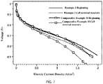
- Example 1 For the performance loss before and after cell reversal, the voltage loss of the small current region (LCD, 0.2A/cm 2 ) and the voltage loss of the high current region (HCD, 1A/cm 2 ) were herein selected to comprehensively reflect the performance loss before and after cell reversal, wherein the membrane electrode assembly components and test conditions of Example 1-Example 2 and Comparative Example 1-Comparative Example 10 are as shown in Table 1: Table 1.
- the membrane electrode assemblies and test conditions thereof described in Table 1 are used to compare the initial performance of the membrane electrode assemblies with the performance after cell reversal for obtaining Table 2.
- Table 2. Initial performance and performance loss after cell reversal for different membrane electrode assemblies 0.2 (before) 0.2 (after) ⁇ V 1 1 (before) 1 (after) ⁇ V 2 Cell reversal tolerance time
- Example 1 0.844V 0.839V 0.005V 0.691V 0.678V 0.013V 40 min
- Example 2 0.823V 0.803V 0.020V 0.692V 0.667V 0.025V 90 min
- Comparative Example 1 0.804V 0.784V 0.02V 0.688V 0.570V 0.118V 40 min
- Comparative Example 2 0.827V 0.811V 0.016V 0.692V 0.666V 0.026V 40 min
- Comparative Example 3 0.820V 0.828V -0.008V 0.696V 0.697V -0.001V 1.6V, 2h Comparative Example 4
- Example 2 Comparative Example 2
- the high mass fraction of Pt (Ir) reduces the amount of carbon carrier, so that less carbon is corroded, thereby significantly extending the cell reversal tolerance time.
- Comparative Example 1 and Comparative Example 9 that the carriers of the OER catalyst and the HOR catalyst provided by Comparative Example 1 are graphitized Ketjen Black GrC, and the carriers of the OER catalyst and HOR catalyst provided by Comparative Example 9 are Ketjen Black C.
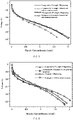
- the membrane electrode assembly provided by Comparative Example 1 has a longer cell reversal tolerance time and less performance loss after cell reversal, which indicates that the corrosion resistance of graphitized Ketjen Black is better than that of Ketjen Black. Further, as can be seen from FIG.
- the carbon carrier is graphitized Ketjen Black
- corrosion rate thereof is relatively slow, which inhibits the shedding of the Ir component, thereby avoiding the sharp rise of the anode potential, slowing down the corrosion of the carbon carrier on the anode side and the shedding of Pt, and finally, the performance loss after cell reversal is reduced.
- Example 1 is compared with Comparative Example 5, under the condition of the same cell reversal tolerance time, the performance loss when the HOR catalyst is respectively distributed in the region near the membrane and the region near the anode diffusion layer is lower than that when the HOR catalyst is entirely distributed in the region near the membrane, which proves that the double-layer design of the HOR catalyst is beneficial to reduce the performance loss after cell reversal. It can be seen from FIG.
- Example 2 is compared with Comparative Example 10, a part of the HOR catalyst in Example 2 is formed on the side of the anode near the membrane layer, and another part is formed on the side of the anode near the anode diffusion layer; and the HOR catalyst provided by Comparative Example 10 is entirely formed on the side of the anode near the membrane layer. It can be seen from the data in the table that under the condition of the same cell reversal time of 90min, the performance loss after cell reversal of the membrane electrode assembly provided by Example 2 is smaller. It shows that the HOR catalyst is respectively distributed in the region near the membrane and the region near the anode diffusion layer, which can significantly reduce carbon corrosion and performance loss after cell reversal while ensuring the initial performance.
- the water of the cathode since the water of the cathode is more than that of the anode in the membrane electrode assembly, the water of the cathode may be reversely diffused to the anode, so the water content in the region of the anode near the membrane is higher than that in the region near the gas diffusion layer.
- the cell reversal mainly occurs on the anode side of the membrane electrode assembly, and the carbon corrosion is jointly determined by the anode potential, the corrosion resistance of the carbon carrier, and the water content near the carbon carrier.
- the membrane electrode assembly and the manufacturing method thereof provided by the embodiments of the present disclosure can not only reduce the performance loss after cell reversal, but also extend the cell reversal tolerance time, so that the performance of the fuel cell is better, which is beneficial to extend the service life of the fuel cell.
Landscapes
- Chemical & Material Sciences (AREA)
- Chemical Kinetics & Catalysis (AREA)
- Electrochemistry (AREA)
- General Chemical & Material Sciences (AREA)
- Engineering & Computer Science (AREA)
- Materials Engineering (AREA)
- Manufacturing & Machinery (AREA)
- Life Sciences & Earth Sciences (AREA)
- Sustainable Development (AREA)
- Sustainable Energy (AREA)
- Composite Materials (AREA)
- Inert Electrodes (AREA)
Applications Claiming Priority (1)
| Application Number | Priority Date | Filing Date | Title |
|---|---|---|---|
| PCT/CN2019/121277 WO2021102739A1 (zh) | 2019-11-27 | 2019-11-27 | 膜电极及其制备方法、燃料电池 |
Publications (2)
| Publication Number | Publication Date |
|---|---|
| EP4068435A1 true EP4068435A1 (de) | 2022-10-05 |
| EP4068435A4 EP4068435A4 (de) | 2024-11-27 |
Family
ID=74978867
Family Applications (1)
| Application Number | Title | Priority Date | Filing Date |
|---|---|---|---|
| EP19954609.4A Pending EP4068435A4 (de) | 2019-11-27 | 2019-11-27 | Membranelektrode; deren herstellungsverfahren und brennstoffzelle |
Country Status (3)
| Country | Link |
|---|---|
| EP (1) | EP4068435A4 (de) |
| CN (1) | CN112534613B (de) |
| WO (1) | WO2021102739A1 (de) |
Families Citing this family (3)
| Publication number | Priority date | Publication date | Assignee | Title |
|---|---|---|---|---|
| CN114204056B (zh) * | 2021-12-10 | 2023-09-19 | 南华大学 | 一种抗反极优化设计膜电极组件结构及优化方法 |
| CN115312821A (zh) * | 2022-09-05 | 2022-11-08 | 三一电动车科技有限公司 | 膜电极、膜电极组件及其制备方法 |
| CN115579496A (zh) * | 2022-10-12 | 2023-01-06 | 广东泰极动力科技有限公司 | 一种高耐久低成本的燃料电池膜电极 |
Family Cites Families (9)
| Publication number | Priority date | Publication date | Assignee | Title |
|---|---|---|---|---|
| JP5151061B2 (ja) * | 2006-04-14 | 2013-02-27 | トヨタ自動車株式会社 | 燃料電池 |
| JP2008027647A (ja) * | 2006-07-19 | 2008-02-07 | Toyota Motor Corp | 燃料電池用燃料極およびそれを備えた燃料電池 |
| US20130022890A1 (en) * | 2011-07-18 | 2013-01-24 | Ford Motor Company | Solid polymer electrolyte fuel cell with improved voltage reversal tolerance |
| EP2770564B1 (de) * | 2013-02-21 | 2019-04-10 | Greenerity GmbH | Barriereschicht für Korrosionsschutz in elektrochemischen Vorrichtungen |
| EP3235039B1 (de) * | 2014-12-15 | 2019-04-17 | 3M Innovative Properties Company | Membranelektrodenanordnung |
| CA2934237A1 (en) * | 2016-06-28 | 2016-08-31 | Daimler Ag | Anode for improved reversal tolerance in fuel cell stack |
| US10714771B2 (en) * | 2016-09-08 | 2020-07-14 | Daimler Ag | Below freezing start-up method for fuel cell system |
| CN109417180B (zh) * | 2016-12-29 | 2022-03-08 | 可隆工业株式会社 | 膜电极组件及其制备方法和包括该膜电极组件的燃料电池 |
| CN108063267B (zh) * | 2017-12-26 | 2020-06-05 | 新源动力股份有限公司 | 一种燃料电池的具有多层结构的催化层及其制备方法 |
-
2019
- 2019-11-27 CN CN201980049374.3A patent/CN112534613B/zh active Active
- 2019-11-27 WO PCT/CN2019/121277 patent/WO2021102739A1/zh not_active Ceased
- 2019-11-27 EP EP19954609.4A patent/EP4068435A4/de active Pending
Also Published As
| Publication number | Publication date |
|---|---|
| CN112534613A (zh) | 2021-03-19 |
| CN112534613B (zh) | 2023-03-24 |
| EP4068435A4 (de) | 2024-11-27 |
| WO2021102739A1 (zh) | 2021-06-03 |
Similar Documents
| Publication | Publication Date | Title |
|---|---|---|
| US6517962B1 (en) | Fuel cell anode structures for voltage reversal tolerance | |
| CN100502112C (zh) | 燃料电池和燃料电池系统的工作方法及燃料电池系统 | |
| US9299998B2 (en) | Fuel cell management method | |
| US20090155635A1 (en) | Method of activating membrane electrode assembly (pem) of polymer electrolyte membrane fuel cell (pemfc) using cyclic voltammetry (cv) | |
| Kongkanand et al. | (Plenary) Electrochemical diagnostics and modeling in developing the PEMFC cathode | |
| US20090246587A1 (en) | Fuel cell | |
| JP6118084B2 (ja) | 燃料電池性能の回復方法 | |
| EP4068435A1 (de) | Membranelektrode; deren herstellungsverfahren und brennstoffzelle | |
| US20150104721A1 (en) | Performance recovery method for fuel cell stack | |
| US12374699B2 (en) | Cathode catalyst layer structure for enhancing durability of catalyst and fabrication method thereof | |
| CN114628745A (zh) | 用于高温质子交换膜燃料电池的极化损失分离方法及系统 | |
| US8647784B2 (en) | Fuel cell stack start method preventing cathode deterioration | |
| KR101664627B1 (ko) | 고분자 전해질막 연료전지 및 이의 제조방법 | |
| CN112670520A (zh) | 一种提升耐久性的高性能质子交换膜燃料电池膜电极结构及其制备方法 | |
| Jo et al. | Effects of a hydrogen and air supply procedure on the performance degradation of PEMFCs | |
| CN111584892A (zh) | 阳极催化剂、膜电极及燃料电池 | |
| KR102123930B1 (ko) | 막 전극 접합체 활성화 방법 | |
| CN218414646U (zh) | 膜电极组件及膜电极 | |
| JP5022707B2 (ja) | 固体高分子電解質型燃料電池 | |
| KR102299218B1 (ko) | 이오노머-이오노머 지지체 복합체, 이의 제조방법 및 상기 이오노머-이오노머 지지체 복합체를 포함하는 연료전지용 촉매 전극 | |
| JP5392139B2 (ja) | 触媒利用率の測定方法 | |
| JP2007018858A (ja) | 燃料電池システム | |
| KR20230039855A (ko) | 역전압 방지를 위한 고분자 전해질 연료전지용 막전극 접합체 | |
| US20050221162A1 (en) | Catalyst structures for electrochemical fuel cells | |
| US20060068269A1 (en) | Electrode structure for solid polymer type fuel cell |
Legal Events
| Date | Code | Title | Description |
|---|---|---|---|
| STAA | Information on the status of an ep patent application or granted ep patent |
Free format text: STATUS: THE INTERNATIONAL PUBLICATION HAS BEEN MADE |
|
| PUAI | Public reference made under article 153(3) epc to a published international application that has entered the european phase |
Free format text: ORIGINAL CODE: 0009012 |
|
| STAA | Information on the status of an ep patent application or granted ep patent |
Free format text: STATUS: REQUEST FOR EXAMINATION WAS MADE |
|
| 17P | Request for examination filed |
Effective date: 20220621 |
|
| AK | Designated contracting states |
Kind code of ref document: A1 Designated state(s): AL AT BE BG CH CY CZ DE DK EE ES FI FR GB GR HR HU IE IS IT LI LT LU LV MC MK MT NL NO PL PT RO RS SE SI SK SM TR |
|
| DAV | Request for validation of the european patent (deleted) | ||
| DAX | Request for extension of the european patent (deleted) | ||
| A4 | Supplementary search report drawn up and despatched |
Effective date: 20241025 |
|
| RIC1 | Information provided on ipc code assigned before grant |
Ipc: H01M 8/10 20160101ALI20241021BHEP Ipc: H01M 8/1004 20160101ALI20241021BHEP Ipc: H01M 4/92 20060101ALI20241021BHEP Ipc: H01M 4/90 20060101ALI20241021BHEP Ipc: H01M 4/88 20060101AFI20241021BHEP |