EP4067732A1 - Lampe pour véhicule dotée d'une surface d'éclairage comprenant une surface de réflecteur - Google Patents
Lampe pour véhicule dotée d'une surface d'éclairage comprenant une surface de réflecteur Download PDFInfo
- Publication number
- EP4067732A1 EP4067732A1 EP21166510.4A EP21166510A EP4067732A1 EP 4067732 A1 EP4067732 A1 EP 4067732A1 EP 21166510 A EP21166510 A EP 21166510A EP 4067732 A1 EP4067732 A1 EP 4067732A1
- Authority
- EP
- European Patent Office
- Prior art keywords
- light
- reflector
- light source
- reflective coating
- vehicle
- Prior art date
- Legal status (The legal status is an assumption and is not a legal conclusion. Google has not performed a legal analysis and makes no representation as to the accuracy of the status listed.)
- Withdrawn
Links
Images


Classifications
-
- F—MECHANICAL ENGINEERING; LIGHTING; HEATING; WEAPONS; BLASTING
- F21—LIGHTING
- F21S—NON-PORTABLE LIGHTING DEVICES; SYSTEMS THEREOF; VEHICLE LIGHTING DEVICES SPECIALLY ADAPTED FOR VEHICLE EXTERIORS
- F21S41/00—Illuminating devices specially adapted for vehicle exteriors, e.g. headlamps
- F21S41/30—Illuminating devices specially adapted for vehicle exteriors, e.g. headlamps characterised by reflectors
- F21S41/37—Illuminating devices specially adapted for vehicle exteriors, e.g. headlamps characterised by reflectors characterised by their material, surface treatment or coatings
-
- B—PERFORMING OPERATIONS; TRANSPORTING
- B60—VEHICLES IN GENERAL
- B60Q—ARRANGEMENT OF SIGNALLING OR LIGHTING DEVICES, THE MOUNTING OR SUPPORTING THEREOF OR CIRCUITS THEREFOR, FOR VEHICLES IN GENERAL
- B60Q1/00—Arrangement of optical signalling or lighting devices, the mounting or supporting thereof or circuits therefor
- B60Q1/26—Arrangement of optical signalling or lighting devices, the mounting or supporting thereof or circuits therefor the devices being primarily intended to indicate the vehicle, or parts thereof, or to give signals, to other traffic
- B60Q1/2607—Arrangement of optical signalling or lighting devices, the mounting or supporting thereof or circuits therefor the devices being primarily intended to indicate the vehicle, or parts thereof, or to give signals, to other traffic comprising at least two indicating lamps
-
- F—MECHANICAL ENGINEERING; LIGHTING; HEATING; WEAPONS; BLASTING
- F21—LIGHTING
- F21S—NON-PORTABLE LIGHTING DEVICES; SYSTEMS THEREOF; VEHICLE LIGHTING DEVICES SPECIALLY ADAPTED FOR VEHICLE EXTERIORS
- F21S41/00—Illuminating devices specially adapted for vehicle exteriors, e.g. headlamps
- F21S41/60—Illuminating devices specially adapted for vehicle exteriors, e.g. headlamps characterised by a variable light distribution
- F21S41/65—Illuminating devices specially adapted for vehicle exteriors, e.g. headlamps characterised by a variable light distribution by acting on light sources
- F21S41/663—Illuminating devices specially adapted for vehicle exteriors, e.g. headlamps characterised by a variable light distribution by acting on light sources by switching light sources
-
- F—MECHANICAL ENGINEERING; LIGHTING; HEATING; WEAPONS; BLASTING
- F21—LIGHTING
- F21S—NON-PORTABLE LIGHTING DEVICES; SYSTEMS THEREOF; VEHICLE LIGHTING DEVICES SPECIALLY ADAPTED FOR VEHICLE EXTERIORS
- F21S43/00—Signalling devices specially adapted for vehicle exteriors, e.g. brake lamps, direction indicator lights or reversing lights
- F21S43/10—Signalling devices specially adapted for vehicle exteriors, e.g. brake lamps, direction indicator lights or reversing lights characterised by the light source
- F21S43/13—Signalling devices specially adapted for vehicle exteriors, e.g. brake lamps, direction indicator lights or reversing lights characterised by the light source characterised by the type of light source
- F21S43/14—Light emitting diodes [LED]
-
- F—MECHANICAL ENGINEERING; LIGHTING; HEATING; WEAPONS; BLASTING
- F21—LIGHTING
- F21S—NON-PORTABLE LIGHTING DEVICES; SYSTEMS THEREOF; VEHICLE LIGHTING DEVICES SPECIALLY ADAPTED FOR VEHICLE EXTERIORS
- F21S43/00—Signalling devices specially adapted for vehicle exteriors, e.g. brake lamps, direction indicator lights or reversing lights
- F21S43/20—Signalling devices specially adapted for vehicle exteriors, e.g. brake lamps, direction indicator lights or reversing lights characterised by refractors, transparent cover plates, light guides or filters
- F21S43/235—Light guides
- F21S43/236—Light guides characterised by the shape of the light guide
- F21S43/239—Light guides characterised by the shape of the light guide plate-shaped
-
- F—MECHANICAL ENGINEERING; LIGHTING; HEATING; WEAPONS; BLASTING
- F21—LIGHTING
- F21S—NON-PORTABLE LIGHTING DEVICES; SYSTEMS THEREOF; VEHICLE LIGHTING DEVICES SPECIALLY ADAPTED FOR VEHICLE EXTERIORS
- F21S43/00—Signalling devices specially adapted for vehicle exteriors, e.g. brake lamps, direction indicator lights or reversing lights
- F21S43/20—Signalling devices specially adapted for vehicle exteriors, e.g. brake lamps, direction indicator lights or reversing lights characterised by refractors, transparent cover plates, light guides or filters
- F21S43/235—Light guides
- F21S43/242—Light guides characterised by the emission area
- F21S43/243—Light guides characterised by the emission area emitting light from one or more of its extremities
-
- F—MECHANICAL ENGINEERING; LIGHTING; HEATING; WEAPONS; BLASTING
- F21—LIGHTING
- F21S—NON-PORTABLE LIGHTING DEVICES; SYSTEMS THEREOF; VEHICLE LIGHTING DEVICES SPECIALLY ADAPTED FOR VEHICLE EXTERIORS
- F21S43/00—Signalling devices specially adapted for vehicle exteriors, e.g. brake lamps, direction indicator lights or reversing lights
- F21S43/20—Signalling devices specially adapted for vehicle exteriors, e.g. brake lamps, direction indicator lights or reversing lights characterised by refractors, transparent cover plates, light guides or filters
- F21S43/235—Light guides
- F21S43/247—Light guides with a single light source being coupled into the light guide
-
- F—MECHANICAL ENGINEERING; LIGHTING; HEATING; WEAPONS; BLASTING
- F21—LIGHTING
- F21S—NON-PORTABLE LIGHTING DEVICES; SYSTEMS THEREOF; VEHICLE LIGHTING DEVICES SPECIALLY ADAPTED FOR VEHICLE EXTERIORS
- F21S43/00—Signalling devices specially adapted for vehicle exteriors, e.g. brake lamps, direction indicator lights or reversing lights
- F21S43/20—Signalling devices specially adapted for vehicle exteriors, e.g. brake lamps, direction indicator lights or reversing lights characterised by refractors, transparent cover plates, light guides or filters
- F21S43/26—Refractors, transparent cover plates, light guides or filters not provided in groups F21S43/235 - F21S43/255
-
- F—MECHANICAL ENGINEERING; LIGHTING; HEATING; WEAPONS; BLASTING
- F21—LIGHTING
- F21S—NON-PORTABLE LIGHTING DEVICES; SYSTEMS THEREOF; VEHICLE LIGHTING DEVICES SPECIALLY ADAPTED FOR VEHICLE EXTERIORS
- F21S43/00—Signalling devices specially adapted for vehicle exteriors, e.g. brake lamps, direction indicator lights or reversing lights
- F21S43/30—Signalling devices specially adapted for vehicle exteriors, e.g. brake lamps, direction indicator lights or reversing lights characterised by reflectors
- F21S43/33—Signalling devices specially adapted for vehicle exteriors, e.g. brake lamps, direction indicator lights or reversing lights characterised by reflectors characterised by their material, surface treatment or coatings
-
- B—PERFORMING OPERATIONS; TRANSPORTING
- B60—VEHICLES IN GENERAL
- B60Q—ARRANGEMENT OF SIGNALLING OR LIGHTING DEVICES, THE MOUNTING OR SUPPORTING THEREOF OR CIRCUITS THEREFOR, FOR VEHICLES IN GENERAL
- B60Q2400/00—Special features or arrangements of exterior signal lamps for vehicles
- B60Q2400/20—Multi-color single source or LED matrix, e.g. yellow blinker and red brake lamp generated by single lamp
Definitions
- the invention relates to a vehicle light according to the preamble of claim 1.
- a vehicle lamp comprises, for example, a lamp interior essentially enclosed by a lamp housing with at least one light opening and a lens closing it, and at least one illuminant housed therein, comprising at least one light source, for at least one lighting function of the vehicle lamp.
- each vehicle light in particular an automobile light, fulfills one or more tasks or functions.
- a light function of the vehicle light is provided to fulfill each task or function.
- Light functions are, for example, a function that illuminates the roadway when configured as a headlight, or a signal function when configured as a signal light, such as a repeating flashing light function to indicate the direction of travel or a brake light function to indicate braking activity, or e.g. a parking light function, such as a rear light function, to ensure a Day and/or night visibility of the vehicle, such as when configured as a rear light or daytime running light.
- Each light function must fulfill a light distribution that is specified by law, for example.
- the light distribution determines at least luminous fluxes to be maintained, colloquially referred to as brightness, in at least solid angle ranges to be maintained.
- At least one light source of the illuminant of a vehicle lamp can be assigned one or more optical elements for light guidance that contribute to the formation of a light distribution.
- each light function When looking from outside the interior of the light onto the lens or through it, each light function is realized in such a way that each light function has its own or part of a common light area available at least while it is being performed at the moment.
- the lens is formed by a nowadays usually made of a plastic, transparent cover, which closes the interior of the lamp and protects the components housed therein, such as one or more lamps, reflectors and alternatively or additionally provided optics elements against weather influences.
- the lamp housing or the interior of the lamp can be divided into several chambers, each with their own light sources and/or illuminants and/or optics elements and possibly light panes, of which several chambers can have the same and/or each chamber can fulfill a different lighting function.
- the optical elements mentioned can be at least one reflector and/or at least one lens and/or one or more optical disks or the like arranged in the beam path between at least one light source of the illuminant and the lens.
- At least one reflector arranged behind at least one light source of at least one lamp can be accommodated in the interior of the lamp.
- Such a reflector which an observer can see through the lens from outside the interior of the lamp, forms at least part of the luminous surface of the vehicle lamp, at least partially surrounds it or is at least partially surrounded by the luminous surface.
- the reflector can be formed at least in part by a separate component and/or by at least part of the lamp housing itself, for example by means of an at least partially reflective coating.
- the lens itself can alternatively or additionally be designed as an optical element, for example by preferably having a light distribution on its inside that contributes to the generation of one or more light distributions mentioned above optical structure is provided. As a result, an optical disk can be dispensed with if necessary.
- vehicle lights are on the front of the vehicle, on the sides of the vehicle and/or on the side mirrors and on the rear of the vehicle, repeater flashing lights, exit lights, for example for ambient lighting, side lights, brake lights, fog lights, reversing lights, and typically high-mounted third brake lights, so-called central, high-mounted Braking lights, daytime running lights, headlights and fog lights used as cornering lights, and combinations thereof.
- Such a combination is, for example, regularly implemented in the known rear lights.
- repeat turn signal lights, position lights, brake lights, fog lights and reversing lights are used, to name just one of many combinations implemented in rear lights. This list does not claim to be complete, nor does it mean that all of the lights mentioned must be combined in one rear light. For example, only two or three of the lights mentioned or other lights can also be combined with one another in a common light housing of a rear light.
- One object of the invention is to develop a vehicle light with a common lighting area for at least two light functions of any light color.
- One object of the invention therefore relates to a vehicle lamp with a lamp interior that is at least partially enclosed by a lamp housing and a lens, in which a reflector is at least partially housed, which forms and/or comprises at least part of a luminous surface for realizing a lighting function of the vehicle lamp, or is comprised of a luminous surface for realizing a light function of the vehicle lamp.
- the reflector comprises a reflector body that is transparent at least for light in a part of the electromagnetic spectrum that is at least visible to the human eye and has a reflector surface that preferably faces at least partially both the lens and a first light source that emits light to be reflected.
- the reflector surface is partially covered with a reflective coating.
- a remaining part of the reflector surface is designed free of the reflective coating.
- the first light source radiates its light into the reflector, which is comprised of the luminous surface for two light functions.
- the reflector deflects the light from the first light source in the direction of the lens.
- a second light source radiates its light from a side facing away from the reflector surface through the reflector body and through the areas of the reflector surface free of the reflective coating in the direction of the lens.
- the remaining part of the reflector surface that is free of the reflective coating can be freed from the reflective coating, for example, by laser cutting.
- the reflector surface is initially provided with a reflective coating over its entire surface, which is partially removed by free lasering in the remaining part of the reflector surface that is free of the reflective coating.
- the second light source radiates its light through the areas of the reflector surface that have been lasered free of the reflective coating.
- the invention preferably provides that a first light source radiates its light into a reflector that forms the luminous surface for two light functions or is enclosed by the luminous surface for two light functions, with a second light source radiating its light through areas that have been lasered free of the reflective coating .
- Advantages over the prior art include a saving in installation space and weight. Additional advantages are the implementation of at least two light functions of any light color within one and the same luminous area. An additional advantage is the creation of a possibility for displaying symbols and characters, for example warnings within a luminous area.
- An advantageous development of the invention deals with the lasering of parts of a previously mirrored surface of an optical element that is transparent at least in a part of the electromagnetic spectrum that is visible to the human eye, with the aim of using the remaining mirrored partial surface of the optical element as a reflector for a first , their light into the reflector to provide the light function realized by the incident light source, and to provide the partial surface of the optical element freed from the reflective coating as an attachment optical element for a light function realized by a second light source that transmits its light through the optical element, at least in the region of the partial surface freed from the reflective coating optically effective structures, such as lens geometries or the like, are applied to the side of the optical element facing the second light source, as a result of which the first and second light functions have different light distributions.
- the light function that shines through is the light function that is realized by the light emitted by the second light source.
- a particularly advantageous development of the invention therefore provides that at least the lasered areas on a side facing the second light source are provided with optically active structures influencing the light distribution of the light radiated through by the second light source.
- the side facing the second light source is the side facing away from the reflector surface, from which the second light source radiates its light through the reflector body and through the areas of the reflector surface free of the reflective coating in the direction of the lens.
- the luminous surface area through which the second light source radiates its light can accordingly be optically structured.
- the optical structuring can be provided on the front and/or rear.
- An advantageous development of the invention provides for free lasering and coding of surfaces, for example free lasering of surfaces to generate at least two light functionalities in an optically structured luminous surface area.
- the invention can be implemented by lasering parts of a reflective coating on a reflector surface with the aim of realizing additional light effects within a luminous surface that is available for one or two light functions of the same light color and includes the reflective coating.
- the vehicle light can have individual or a combination of several features described in the introduction in connection with the prior art and/or in one or more of the documents mentioned on the prior art and/or in the following description of the exemplary embodiments illustrated in the drawings .
- the invention thus creates expanded possibilities for structuring optical elements after they have been vapor-deposited. It also creates extended and more flexible options for displaying lettering, logos, etc., especially in vehicle lights such as automotive lights and headlights. These are, for example, extended and more flexible options for the display of lettering, logos, etc., so that they are compliant with the legal regulations to be observed for automotive lights, such as ECE, FMVSS, SAE, etc., and can be used.
- the invention enables integration of a plurality of light signatures into one and the same visible luminous surface in lights, for example formed by one or more reflectors, optical discs, light discs, etc. or comprised by or comprising such.
- stenciled vapor deposition can be dispensed with.
- Such stenciled vaporizations are associated with limitations that result, for example, from the fact that a shadow mask has to be used whose areas are contiguous have to. For example, for the recess in the shape of a letter "O", the shadow mask must also be inside the "O”. Therefore, connecting webs from outside to inside the "O” are required, which have negative effects on the "O" contour, since interruptions in the contour are required.
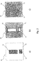
- the vehicle light 01 shown in whole or in part comprises a light interior 04 that is at least partially enclosed by a light housing 02 and a lens 03.
- a reflector 05 is accommodated at least in part in the interior space 04 of the lamp.
- Reflector 05 forms and/or comprises at least part of a luminous surface for implementing at least one lighting function of vehicle light 01, or it is surrounded by a luminous surface for implementing a lighting function of vehicle light 01.
- the reflector 05 comprises a reflector body 50 that is transparent at least to light in a part of the electromagnetic spectrum that is at least visible to the human eye and has a reflector surface 51 that preferably faces both the lens 03 and a first light source 06, which at least partially faces the light to be reflected.
- the reflector surface 51 is partially provided with a reflective coating. A remaining part 52 of the reflector surface 51 is designed free of the reflective coating.
- the already mentioned first light source 06 radiates its light into the reflector 05 by radiating its light onto the reflector surface 51 which is covered by the luminous surface for two light functions, for example.
- In 12 is the optical path of the of the the light emitted by the first light source 06 is illustrated by way of example by the marginal rays shown in dashed lines.
- a second light source 07 radiates its light from a side facing away from reflector surface 51 through reflector body 50 and through remaining part 52 of reflector surface 51, which is divided into several areas free of the reflective coating, for example in the direction of lens 03.
- the beam path of the light emitted by the second light source 07 is also shown as an example by marginal rays drawn in with dots.
- the reflector 05 preferably deflects the light from the first light source 06 in the direction of the lens 03.
- the second light source 07 radiates its light through the reflector body 50 and through the remaining part 52 of the reflector surface 51, which is divided into several areas free of the reflective coating, for example also preferably in the direction of the lens 03.
- the first light source 06 can be part of a first light source 60 comprising a conductor track carrier and optionally one or more electronic components.
- a first light source 60 can include a plurality of first light sources 06.
- the second light source 07 can be part of a second light source 70 comprising a conductor track carrier and optionally one or more electronic components.
- a second light source 70 can also include a plurality of second light sources 07.
- the first light source 06 and/or the second light source 07 can advantageously be embodied as semiconductor light sources.
- Semiconductor light sources such as LEDs (inorganic light-emitting diodes) and/or OLEDs (organic light-emitting diodes) have a very short, barely measurable activation time from the start of current application to the emission of light. In contrast to an incandescent lamp, the light is emitted with full luminosity proportional to the current intensity from the moment the current is applied. In addition, they are highly efficient in converting electrical current into light visible to the human eye. Furthermore, LEDs in particular have a very long service life when used in vehicle lights.
- the reflector surface 51 is initially provided with a reflective coating over its entire surface, which is partially removed again by free lasering in the remaining part 52 of the reflector surface 51 that is free of the reflective coating.
- the second light source 07 radiates its light through the areas of the reflector surface 51 that have been lasered free of the reflective coating.
- a first light source 06 radiates its light into a reflector 05 that forms the luminous surface for one or more, for example for two, lighting functions or is comprised by the luminous surface for one or more, preferably for two, lighting functions, with one second light source 07 transmits its light through areas that have been lasered free of the reflective coating.
- this allows the display of logos/warning notices, for example, within the luminous area formed by the reflector surface 51, for example by activating only one light function.
- the entire luminous surface surrounding and/or surrounded by the reflector 05 lights up in the light color.
- a logo that is visible in the switched-off state can be displayed on the reflector 05 by appropriately fine structuring.
- first light source 06 and the second light source 07 have different light colors
- logos and/or warnings can also be displayed within the luminous area formed by the reflector surface 51, even if both light functions are activated at the same time.
- Advantages over the prior art include a saving in installation space and weight. Additional advantages are the implementation of at least two light functions of any light color within one and the same luminous area. An additional advantage is the creation of a possibility for displaying symbols and characters, for example warnings within a luminous area.
- the new type of vehicle light 01 makes it possible to design new light functionalities, for example through partial laser ablation of, for example, vapour-coated surfaces and, alternatively or additionally, flexible adaptation of light signatures through dedicated lighting of components.
- 1 and 12 show the possibility of using the reflector 05 for a light function when it is irradiated from above with the first light source 06, which is implemented, for example, by a plurality of LEDs, and on the other hand as an alternative light function, when the second light source 07, which is also implemented, for example, by a plurality of LEDs, from behind is used - possibly also together with the LEDs of the first light source 06 that shine in from above.
- the individual areas of the remaining part 52 of the reflector surface 51 which is free of the reflective coating, or generally on an optical element made of a transparent body with a surface partially provided with a reflective coating, are selected to be sufficiently small, it is no longer visible to the observer from a corresponding distance recognizable that incomplete visual signatures are displayed on the reflector. This is the case in particular when viewing in the so-called far field from a distance of preferably 10 m to the light function. A homogeneous light signature can therefore also be realized with such configurations.
- first and second light sources 06, 07 realized for example by several LEDs, of the respective other light function also light up with low intensity in order to make the gaps in the light signature less noticeable. This is particularly advantageous for near-field viewing from a distance of less than 10 m.
- both areas are then activated for the display, so that the luminances of the transparent and the reflective areas approach one another.
- the back-injection molding of a printed film is disadvantageous because a directed, metallically reflecting surface can only be produced as a printed pattern with difficulty.
- the further description is based on the example of a light function with reflector 05.
- logos and/or design elements should be placed on such a reflector 05, which are visible when the light function is switched off but not visible when it is switched on.
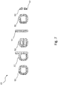
- the logo or design element on the reflector is not lasered over the entire surface, but only as a fine dot pattern 53, as in 8 , 9 , 10 , 11 shown.
- the remaining part 52 of the reflector surface 51 is designed as a dot pattern 53 .
- Such a pattern of small non-metallized areas cannot be produced with conventional methods.
- the dot pattern 53 is visible as a logo and/or design element on the reflector 05.
- the small, non-reflecting areas are completely outshone when the lighting is switched on, so that at least in the far field only a homogeneously illuminated area is visually perceptible.
- the design can be such that instead of individual prisms, individually reflecting areas are used.
- the result can be designed in such a way that the light signature is executed accordingly.
- a logo or design element with such a design can still be visible up to a certain maximum distance in the near field even when illuminated.
- This maximum distance will turn out to be smaller in the illuminated state than in the case of ambient light in the unilluminated state if non-reflecting, lasered points of the point pattern 53 occur instead of the luminous decoupling prisms.
- the appearance is then inverted compared to an embodiment with luminous decoupling prisms.
- the then non-illuminating dots of the dot pattern 53 are outshined by the luminous surrounding surface, so that they disappear even at a relatively small viewing distance.
- the lasered area in the area of the lettering and/or logo and/or design element is not the same as the lasered area outside of the lettering and/or logo and/or design element, but areas are also lasered there in order to achieve a more homogeneous overall appearance when illuminated achieve without reducing the visibility of the lettering and/or logo and/or design elements too much when switched off.
- vehicle lamp 01 provides that at least one section of reflector body 50, through which section the second light source 07 transmits its light from the side facing away from reflector surface 51, through reflector body 50 and through that part 52 of the reflector surface that is free of the reflective coating 51 preferably shines through in the direction of the lens 03, is provided with optically active structures that influence the light distribution of the light that is radiated through the section by the second light source 07.
- a particularly advantageous development therefore provides that at least the remaining part 52 of the reflector surface 51, which is free of the reflective coating, for example the lasered areas of a reflector surface 51 that was previously mirrored over its entire surface, should be on a side lying in the beam path of the second light source 07 and facing it the light distribution of the light radiated through by the second light source 07 is provided with optically active structures.
- the side facing the second light source 07 is the side facing away from the reflector surface 51, from which the second light source 07 transmits its light through the reflector body 50 and through the light from the reflective coating 51 free areas of the reflector surface 51 radiates through, for example in the direction of lens 03.
- the luminous surface area through which the second light source 07 radiates its light can therefore be optically structured for the purpose of influencing the light distribution of the light passing through the luminous surface area.
- Such a different influencing of the light distribution of the light emitted by the first light source 06 and the light distribution of the light emitted by the second light source 07 is in 12 by a schematic representation of a different widening of the beam path of the light emitted by the first light source 06, for example by marginal rays drawn in dashed lines, and of the beam path of the light emitted by the second light source 07, also shown by way of example by marginal rays drawn in dashed lines.
- optically active structures that are designed, for example, as optical structuring and/or include such structures can be arranged on the front and/or rear of the reflector body 50 with respect to the light from the second light source 07 passing through it.
- This advantageous further development of the invention provides, for example, for parts of a previously mirrored surface forming a reflector surface to be lasered free of an optical element which forms a reflector body and is transparent at least in a part of the electromagnetic spectrum that is visible to the human eye, with the aim of removing the remaining part Provide the surface of the optical element as a reflector for a light function realized by a first light source, which radiates its light into the reflector, and to provide the part of the optical element with the partial surface freed from the mirror coating as an attachment optical element for a light function realized by a second light source , which transmits its light through the optical element.
- optically effective structures designed and/or comprising such an optical structuring can comprise lens geometries and/or fields.
- Optically active structures such as lens geometries or the like, can advantageously be applied at least in the area of the partial surface that is spared or, for example, freed from the mirror coating on the side of the reflector 05 that forms an optical element that faces the second light source 07.
- the first and the second light function have different light distributions.
- the advantageous development of the invention thus supplements the configurations described above with the aspect that the light function passing through it passes through macroscopic optical elements such as lenses or optically effective structures formed by microlens arrays, which causes an adaptation of the light distribution of the light function passing through.
- the light function that shines through is the light function that is implemented by the light emitted by the second light source 07 .
- the exemplary embodiment shown also shows in particular the possibility of using the reflector 05, more precisely its reflector surface 51, as a luminous surface for a tail light function referred to as SL (tail light) for short, when it is irradiated from above with light from the first light source 06 implemented by LEDs, and on the other hand as a luminous surface for a brake light function referred to as BRL (brake light) for short, if the LEDs that implement the second light source 07 are used from behind.
- SL tail light
- BRL brake light
- a “BRL booster” can also be implemented, including the LEDs of the first light source 06.
- narrower light distributions can be realized for the representation of BRL functions and further emission areas can be realized for SL according to the reflective areas on the reflector element. It is thus possible to decouple the areas and functions.
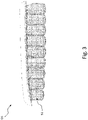
- a reflector 05 with a partially lasered reflector surface 51, with a remaining part 52 of the reflector surface 51, which is subdivided, for example, into several areas and is free of the reflective coating, through which one or more second light sources 07 shine from behind becomes.
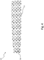
- the divided into several areas Remaining part 52 of the reflector surface 51, which is designed to be free of the reflective coating, can, for example, like an in 4 shown checkerboard pattern be executed.
- the remaining part 52 can also be distributed over a number of sub-areas of a reflector surface 51 distributed over a number of reflector vanes.
- Each field of the checkerboard pattern lasered free of the reflective coating has its own transparent lens arranged in the beam path of the light emitted from the second light source 07 through the reflector body 50 and the remaining part 52 of the reflector surface 51 that has been lasered free.
- a faceted optic can be formed here.
- the light is shaped by the transparent optics on the reflector 05 according to a given wish;
- the reflector substrate from which the reflector body 50 is made is transparent.
- the reflector 05 was first vaporized over its entire surface on its reflector surface 51 .
- the reflector 05 was then partially lasered free on its reflector surface 51, so that the reflective coating, for example made of aluminum, has disappeared in these areas and the transparent reflector substrate reappears.
- the remaining part 52 of the reflector surface 51 that is free of the reflective coating is subsequently formed after the full-area vaporization.
- the reflector surface 51 of a transparent reflector body 50 can first be vaporized over its entire surface. After the vapor deposition, the reflector 05 can be partially lasered free in the mentioned area of its reflector surface 51.
- An advantageous development of the invention provides for free lasering and coding of surfaces, for example free lasering of surfaces to generate at least two light functionalities in an optically structured luminous surface area.
- the remaining part 52 of the reflector surface 51 that is free of the reflective coating is designed, for example, in the shape of its outline and/or shape and/or geometry according to a coding of a light signature.
- the vehicle lamp 01 can comprise at least two lamps 60, 70, each comprising at least one light source 06, 07, a first lamp 60 with at least the first light source 06 to fulfill at least one first lighting function of the vehicle lamp 01, and a second lamp with at least the second light source 07 to fulfill at least one second lighting function of the vehicle lamp 01.
- the at least one first light source 06 and the at least one second light source 07 can advantageously be operated independently of one another.
- the invention can be implemented by lasering parts of a reflective coating of a reflector surface 51 with the aim of realizing additional light effects within a luminous surface that is available for one or two light functions of the same or different light color and that includes the reflective coating.
- the invention expands the prior art in that a first light source radiates its light into a reflector forming the luminous surface for two light functions, and that a second light source transmits its light through areas lasered free of the reflective coating. This allows the display of logos and/or warnings, for example, through the free design of the lasered areas.
- the invention expands the design freedom of lights and creates new possibilities, particularly in the design of light signatures and the coding of light signatures.
- the invention significantly expands the design options for optical systems.
- the vehicle light 01 can alternatively or additionally be individual or a combination of several, introduced in connection with the prior art and/or in one or more of the documents mentioned as prior art and/or the features mentioned in the preceding description and/or in the following claims.
- the invention is not limited by the description based on the exemplary embodiments. Rather, the invention encompasses every new feature and every combination of features, which in particular includes every combination of features in the claims, even if this feature or this combination itself is not explicitly specified in the claims or exemplary embodiments.
- the invention can be used commercially in particular in the field of manufacturing vehicle lights, in particular motor vehicle lights.
Priority Applications (1)
| Application Number | Priority Date | Filing Date | Title |
|---|---|---|---|
| EP21166510.4A EP4067732A1 (fr) | 2021-04-01 | 2021-04-01 | Lampe pour véhicule dotée d'une surface d'éclairage comprenant une surface de réflecteur |
Applications Claiming Priority (1)
| Application Number | Priority Date | Filing Date | Title |
|---|---|---|---|
| EP21166510.4A EP4067732A1 (fr) | 2021-04-01 | 2021-04-01 | Lampe pour véhicule dotée d'une surface d'éclairage comprenant une surface de réflecteur |
Publications (1)
| Publication Number | Publication Date |
|---|---|
| EP4067732A1 true EP4067732A1 (fr) | 2022-10-05 |
Family
ID=75362380
Family Applications (1)
| Application Number | Title | Priority Date | Filing Date |
|---|---|---|---|
| EP21166510.4A Withdrawn EP4067732A1 (fr) | 2021-04-01 | 2021-04-01 | Lampe pour véhicule dotée d'une surface d'éclairage comprenant une surface de réflecteur |
Country Status (1)
| Country | Link |
|---|---|
| EP (1) | EP4067732A1 (fr) |
Citations (10)
| Publication number | Priority date | Publication date | Assignee | Title |
|---|---|---|---|---|
| DE10139812A1 (de) * | 2001-08-14 | 2003-02-27 | Hella Kg Hueck & Co | Beleuchtungseinrichtung |
| DE102006029412A1 (de) * | 2006-06-27 | 2008-01-03 | Automotive Lighting Reutlingen Gmbh | Kraftfahrzeugleuchte |
| DE102008057538A1 (de) * | 2008-11-08 | 2009-07-09 | Daimler Ag | Fahrzeugleuchte |
| DE102012007227A1 (de) * | 2012-04-07 | 2012-11-08 | Daimler Ag | Beleuchtungsvorrichtung und Fahrzeugleuchte mit einer Beleuchtungsvorrichtung |
| DE102011104055A1 (de) * | 2011-06-11 | 2012-12-13 | Volkswagen Aktiengesellschaft | Leuchteinrichtung für ein Fahrzeug |
| DE102012100816A1 (de) * | 2012-02-01 | 2013-08-01 | Dr. Ing. H.C. F. Porsche Aktiengesellschaft | Fahrzeugleuchte |
| US20160040847A1 (en) * | 2013-03-27 | 2016-02-11 | Koito Manufacturing Co., Ltd. | Vehicle lamp |
| DE102015216744A1 (de) * | 2015-09-02 | 2017-03-02 | Volkswagen Aktiengesellschaft | Fahrzeugleuchte und Verfahren zum Bereitstellen einer Lichtfunktion mittels einer Fahrzeugleuchte |
| DE102017122207A1 (de) * | 2017-09-26 | 2019-03-28 | HELLA GmbH & Co. KGaA | Beleuchtungsvorrichtung für ein Kraftfahrzeug |
| DE102019117246A1 (de) | 2019-06-26 | 2020-12-31 | Odelo Gmbh | Leuchtmittel mit Lichtboosterfunktion und hiermit ausgestattete Fahrzeugleuchte |
-
2021
- 2021-04-01 EP EP21166510.4A patent/EP4067732A1/fr not_active Withdrawn
Patent Citations (10)
| Publication number | Priority date | Publication date | Assignee | Title |
|---|---|---|---|---|
| DE10139812A1 (de) * | 2001-08-14 | 2003-02-27 | Hella Kg Hueck & Co | Beleuchtungseinrichtung |
| DE102006029412A1 (de) * | 2006-06-27 | 2008-01-03 | Automotive Lighting Reutlingen Gmbh | Kraftfahrzeugleuchte |
| DE102008057538A1 (de) * | 2008-11-08 | 2009-07-09 | Daimler Ag | Fahrzeugleuchte |
| DE102011104055A1 (de) * | 2011-06-11 | 2012-12-13 | Volkswagen Aktiengesellschaft | Leuchteinrichtung für ein Fahrzeug |
| DE102012100816A1 (de) * | 2012-02-01 | 2013-08-01 | Dr. Ing. H.C. F. Porsche Aktiengesellschaft | Fahrzeugleuchte |
| DE102012007227A1 (de) * | 2012-04-07 | 2012-11-08 | Daimler Ag | Beleuchtungsvorrichtung und Fahrzeugleuchte mit einer Beleuchtungsvorrichtung |
| US20160040847A1 (en) * | 2013-03-27 | 2016-02-11 | Koito Manufacturing Co., Ltd. | Vehicle lamp |
| DE102015216744A1 (de) * | 2015-09-02 | 2017-03-02 | Volkswagen Aktiengesellschaft | Fahrzeugleuchte und Verfahren zum Bereitstellen einer Lichtfunktion mittels einer Fahrzeugleuchte |
| DE102017122207A1 (de) * | 2017-09-26 | 2019-03-28 | HELLA GmbH & Co. KGaA | Beleuchtungsvorrichtung für ein Kraftfahrzeug |
| DE102019117246A1 (de) | 2019-06-26 | 2020-12-31 | Odelo Gmbh | Leuchtmittel mit Lichtboosterfunktion und hiermit ausgestattete Fahrzeugleuchte |
Similar Documents
| Publication | Publication Date | Title |
|---|---|---|
| WO2017042345A1 (fr) | Dispositif d'éclairage pour véhicules | |
| AT517394B1 (de) | Beleuchtungseinrichtung für ein Kraftfahrzeug mit lumineszierenden Elementen | |
| DE102018208822B4 (de) | Leuchtvorrichtung für ein Fahrzeug und zugehörige Heckklappe | |
| EP1757487A1 (fr) | Rétroviseur extérieur pour véhicules | |
| DE19538771B4 (de) | Außenrückblickspiegel für Fahrzeuge, vorzugsweise für Kraftfahrzeuge | |
| EP3344915B1 (fr) | Dispositif d'éclairage de véhicule et procédé de fourniture d'une fonction d'éclairage au moyen d'un dispositif d'éclairage de véhicule | |
| DE202016106347U1 (de) | Beleuchtete Plakette für ein Fahrzeug | |
| WO2020043532A1 (fr) | Dispositif d'éclairage destiné à un véhicule automobile | |
| DE102012211821B4 (de) | Leuchteneinheit für ein Kraftfahrzeug, bei der in einer Gehäuseschale mit Fensterabschnitt Leuchtmittel angeordnet sind | |
| DE102011051152A1 (de) | Verfahren zum Betrieb einer Leuchte sowie Leuchte für ein Fahrzeug | |
| DE102018002721B4 (de) | Beleuchtungsvorrichtung für ein Fahrzeug | |
| DE19838224C2 (de) | Frontleuchtenanordnung für Kraftfahrzeuge | |
| DE10341572B4 (de) | Fahrzeugleuchte mit Elektrolumineszenz-Anordnung | |
| EP2146138A1 (fr) | Eclairage | |
| EP4067732A1 (fr) | Lampe pour véhicule dotée d'une surface d'éclairage comprenant une surface de réflecteur | |
| DE102004046408A1 (de) | Komponente eines Kraftfahrzeug-Scheinwerfers, Front-Scheinwerfer für ein Kraftfahrzeug sowie Verfahren zur Herstellung einer Scheinwerfer-Komponente | |
| DE102015108804A1 (de) | Fahrzeugkomponente | |
| EP1762777B1 (fr) | Dispositif d'éclairage pour véhicule automobile | |
| DE102013016424B4 (de) | Beleuchtungsvorrichtung für eine Kraftfahrzeugaußenbeleuchtung | |
| EP3814172B1 (fr) | Procédé de fabrication d'un module de clignotant ainsi que module de clignotant, système de rétroviseur et véhicule automobile | |
| EP2565527A1 (fr) | Lampe de signalisation pour véhicules automobiles | |
| EP2020565A1 (fr) | Dispositif d'éclairage | |
| EP3677831A1 (fr) | Lampe pour véhicule et procédé de génération d'une surface lumineuse minimale dans une fonction d'éclairage d'une lampe pour véhicule | |
| DE102018102803A1 (de) | Beleuchtungsvorrichtung für Fahrzeuge | |
| EP0921034B1 (fr) | Feux ou phares |
Legal Events
| Date | Code | Title | Description |
|---|---|---|---|
| PUAI | Public reference made under article 153(3) epc to a published international application that has entered the european phase |
Free format text: ORIGINAL CODE: 0009012 |
|
| STAA | Information on the status of an ep patent application or granted ep patent |
Free format text: STATUS: THE APPLICATION HAS BEEN PUBLISHED |
|
| AK | Designated contracting states |
Kind code of ref document: A1 Designated state(s): AL AT BE BG CH CY CZ DE DK EE ES FI FR GB GR HR HU IE IS IT LI LT LU LV MC MK MT NL NO PL PT RO RS SE SI SK SM TR |
|
| STAA | Information on the status of an ep patent application or granted ep patent |
Free format text: STATUS: THE APPLICATION IS DEEMED TO BE WITHDRAWN |
|
| 18D | Application deemed to be withdrawn |
Effective date: 20230406 |